1
BA_MS280C_86_U_J6.book Seite 0 Montag, 4. September 2006 1:47 13
STIH)
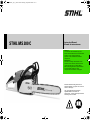
STIHL MS 280 C
Instruction Manual
Manual de instrucciones
Warning!
To reduce the risk of kickback injury use
STIHL reduced kickback bar and STIHL RM2
or RMC3 (.325") chain depending on
sprocket or other available low kickback
components.
Advertencia!
Para reducir el riesgo de lesionarse como
resultado de un culatazo, utilice la barra de
contragolpe reducido y la cadena RM2 o
RMC3 (.325 pulg) de STIHL, dependiendo de
la rueda dentada usada y de otros
componentes reductores de contragolpe.
Read and follow all safety precautions in
Instruction Manual – improper use can cause
serious or fatal injury.
Lea y siga todas las precauciones de
seguridad dadas en el manual de
instrucciones – el uso incorrecto puede causar
lesiones graves o mortales.
English / USA
© ANDREAS STIHL AG & Co. KG, 2006
0458 150 8621 A. M0,5. J6. CP. Printed in USA
Printed on chlorine-free paper.
Printing inks contain vegetable oils; paper can be recycled.
BA_SE_122_003_01_04.fm
Contents
Secondary Chain
Braking System ................................ 2
Guide to Using this Manual .............. 3
Some Important Safety Precautions
for Chain Saw Users ........................ 4
Safety Precautions and Working
Techniques ....................................... 6
Mounting the Bar and Chain
(Side chain tensioner) .................... 29
Mounting the Bar and Chain
(Quick Chain Tensioner) ................. 30
Tensioning the Saw Chain
(Side chain tensioner) .................... 33
Tensioning the Saw Chain
(Quick chain tensioner) .................. 34
Checking Chain Tension ................. 34
Fuel ................................................ 34
Fueling ............................................ 35
Chain Lubricant .............................. 37
Filling Chain Oil Tank ...................... 37
Checking Chain Lubrication ........... 38
Chain Brake ................................... 38
Winter Operation ............................ 40
Information Before You Start .......... 41
Starting / Stopping the Engine ........ 41
Operating Instructions .................... 44
Taking Care of Guide Bar ...............
Air Filter System .............................
Cleaning the Air Filter .....................
Motor Management ........................
Adjusting the Carburetor ................
Spark Arresting Screen
in Muffler ........................................
Checking the Spark Plug ................
Replacing Starter Rope
and Rewind Spring .........................
Storing the Machine .......................
Checking and Replacing
Chain Sprocket ...............................
Maintaining and Sharpening
Saw Chain ......................................
Maintenance Chart .........................
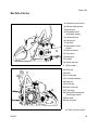
Main Parts of the Saw ....................
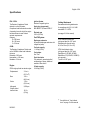
Specifications .................................
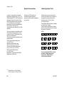
Special Accessories .......................
Ordering Spare Parts .....................
Maintenance and Repairs ..............
STIHL Incorporated
Federal Emission Control
Warranty Statement ........................
Trademarks ....................................
45
46
46
47
47
49
50
Allow only persons who understand this
Manual to operate your chainsaw.
To receive maximum performance and
satisfaction from your STIHL chainsaw,
it is important that you read and
understand the maintenance and safety
precautions, starting on page 4, before
using your chainsaw.
54
Contact your STIHL dealer or the STIHL
distributor for your area if you do not
understand any of the instructions in this
Manual.
55
59
61
63
64
64
65
Because a chainsaw is a high-speed
wood-cutting tool, some special safety
precautions must be observed as with
any other power saw to reduce the risk
of personal injury.
51
53
66
68
!Warning!
Careless or improper use may cause
serious or even fatal injury.
STIHL's philosophy is to continually
improve all of its products. As a result,
engineering changes and improvements
are made from time-to-time. If the
operating characteristics or the
appearance of your chainsaw differs
from those described in this Manual,
please contact your STIHL dealer for
information and assistance.
STIHl
MS 280 C
1
English / USA
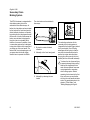
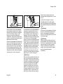
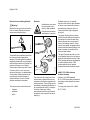
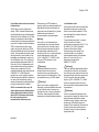
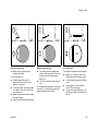
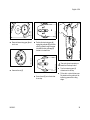
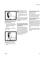
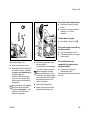
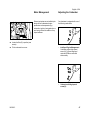
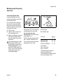
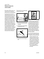
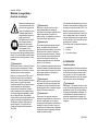
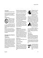
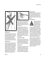
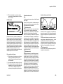
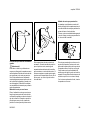
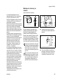
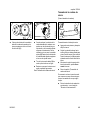
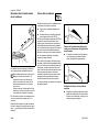
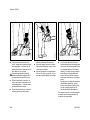
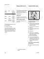
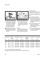
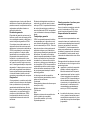
Secondary Chain
Braking System
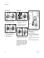
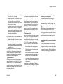
The chain brake can be activated in
three ways:
2
1
150BA000 KN
This STIHL chainsaw is equipped with a
chain brake system that can be
activated in three different ways. As
before, the chain brake can be activated
by the inertia of the front hand guard in
certain kickback situations or manually
by pushing the front hand guard toward
the bar nose. In both of these cases the
brake, once activated, is designed to
bring the chain to a standstill within
fractions of a second. In addition, there
is a secondary system that is designed
to stop chain rotation within a second of
you letting go of the rear handle. The
locked chain is not released again until
you press down the throttle trigger
interlock lever to operate the throttle.
1
By inertia in certain kickback
situations
2
Manually via the front hand guard
3
2
Manually by releasing the rear
handle
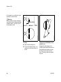
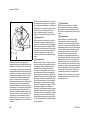
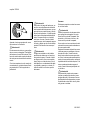
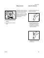
The activating mechanism for the
secondary chain braking system is
integrated in the throttle trigger interlock
lever (rear handle). One of the big
advantages of this system is that the
saw chain is automatically locked in
position for engine starts and when
carrying the running saw by the front
handle (with the rear handle released).
To reduce the risk of personal injury
or property damage during cutting,
observe the characteristics that
make this saw different from saws
not equipped with a secondary
chain braking system. Before
operating the chainsaw for the first
time, make sure you are familiar
with how the rear-handle activation
works. Pay special attention to the
chapters "Chain Brake" and
"Starting/Stopping the Engine".
MS 280 C
English / USA
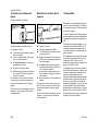
Guide to Using this Manual
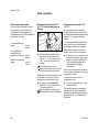
Pictograms
All the pictograms attached to the
machine are shown and explained in
this manual.
The operating and handling instructions
are supported by illustrations.
In addition to the operating instructions,
this manual may contain paragraphs
that require your special attention. Such
paragraphs are marked with the
symbols described below:
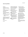
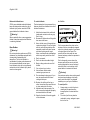
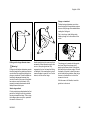
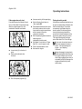
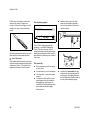
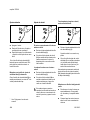
Symbols in text
Warning where there is a risk of an
accident or personal injury or
serious damage to property.
The individual steps or procedures
described in the manual may be marked
in different ways:
Caution where there is a risk of
damaging the machine or its
individual components.
:
Note or hint which is not essential
for using the machine, but may
improve the operator’s understanding of the situation and result
in better use of the machine.
A bullet marks a step or procedure
without direct reference to an
illustration.
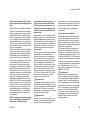
A description of a step or procedure that
refers directly to an illustration may
contain item numbers that appear in the
illustration.
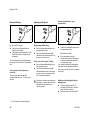
Example:
Loosen the screw (1)
Lever (2) ...
MS 280 C
Note or hint on correct procedure in
order to avoid damage to the
environment.
Equipment and features
This instruction manual may refer to
several models with different
features. Components that are not
installed on all models and related
applications are marked with an
asterisk (*). Such components may
be available as special accessories
from your STIHL dealer.
Engineering improvements
STIHL’s philosophy is to continually
improve all of its products. As a result,
engineering changes and improvements
are made from time to time. If the
operating characteristics or the
appearance of your machine differ from
those described in this manual, please
contact your STIHL dealer for
assistance.
Therefore some changes, modifications
and improvements may not be covered
in this manual.
3
English / USA
Some Important Safety Precautions for Chain Saw Users
A.
A Summary of Warnings on
kickback and other Selected
Risks – Taken Primarily from
ANSI B 175.1 (See also the
“Safety Precautions“ section of
this Owner’s Manual)
Do not rely exclusively upon the safety
devices built into your saw. As a
chainsaw user, you should take several
steps to keep your cutting jobs free from
accident or injury.
1.
!Warning!
Kickback may occur when the nose or
tip of the guide bar touches an object, or
when the wood closes in and pinches
the saw chain in the cut. Tip contact in
some cases may cause a lightning fast
reverse reaction, kicking the guide bar
up and back towards the operator.
Pinching the saw chain along the top of
the guide bar may push the guide bar
rapidly back towards the operator. Either
of these reactions may cause you to lose
control of the saw which could result in
serious personal injury.
Section 5.11 of ANSI B 175.1-2000 sets
certain performance and design criteria
related to chainsaw kickback. STIHL has
developed a color code system using
green and yellow to help you select a
powerhead, bar and chain combination
that complies with the kickback
requirements of the ANSI Standard.
See the sections entitled "Safety
Precautions" and "Specifications" of this
manual.
4
2.
3.
With a basic understanding of
kickback, you can reduce or
eliminate the element of surprise.
Sudden surprise contributes to
accidents.
Keep a good firm grip on the saw
with both hands, the right hand on
the rear handle, and the left hand on
the front handle, when the engine is
running. Use a firm grip with thumbs
and fingers encircling the chainsaw
handles. A firm grip will help you
reduce kickback and maintain
control of the saw. Don't let go.
Make sure the area in which you are
cutting is free from obstructions. Do
not let the nose of the guide bar
contact a log, branch, or any other
obstruction that could be hit while
you are operating the saw.
4.
Cut at high engine speeds.
5.
Do not overreach or cut above
shoulder height.
6.
Follow manufacturer's sharpening
and maintenance instructions for
the saw chain.
7.
Only use replacement bars and
chains specified by the
manufacturer or the equivalent.
8.
Reduced kickback bars and low
kickback chains are designed to
reduce the risk of kickback injury.
Ask your STIHL dealer about these
devices.
B.
Other Safety Precautions
!Warning!
1.
Do not operate a chainsaw with one
hand! Serious injury to the operator,
helpers, bystanders, or any
combination of these persons may
result from one-handed operation. A
chainsaw is intended to be used
with two hands.
2.
Do not operate a chainsaw when
you are fatigued.
3.
Use safety footwear; snug-fitting
clothing; protective gloves; and eye,
hearing, and head protection
devices.
MS 280 C
English / USA
4.
Use caution when handling fuel.
Move the chainsaw at least 10 feet
(3 m) from the fueling point before
starting the engine.
5.
Do not allow other persons to be
near the chainsaw when starting or
cutting with the chainsaw. Keep
bystanders and animals out of the
work area.
6.
7.
8.
9.
Do not start cutting until you have a
clear work area, secure footing, and
a planned retreat path from the
falling tree.
Keep all parts of your body away
from the saw chain when the engine
is running.
Before you start the engine, make
sure that the saw chain is not
contacting anything.
Carry the chainsaw with the engine
stopped, the guide bar and saw
chain to the rear, and the muffler
away from your body.
MS 280 C
10. Do not operate a chainsaw that is
damaged, improperly adjusted, or
not completely and securely
assembled. Be sure that the saw
chain stops moving when the
throttle trigger is released.
11. Shut off the engine before setting
the chainsaw down.
12. Use extreme caution when cutting
small size brush and saplings
because slender material may catch
the saw chain and be whipped
toward you or pull you off balance.
13. When cutting a limb that is under
tension be alert for springback so
that you will not be struck when the
tension in the wood fibers is
released.
14. Keep the handles dry, clean, and
free of oil or fuel mixture.
15. Operate the chainsaw only in wellventilated areas.
16. Do not operate a chainsaw in a tree
unless you have been specifically
trained to do so.
17. All chainsaw service, other than the
items listed in the Owner's Manual
maintenance instructions, should be
performed by competent chainsaw
service personnel.(For example, if
improper tools are used to remove
the flywheel or if an improper tool is
used to hold the flywheel in order to
remove the clutch, structural
damage to the flywheel could occur
and could subsequently cause the
flywheel to burst).
18. When transporting your chainsaw,
use the appropriate chain guard
(scabbard).
Other important safety precautions are
contained in the body of the Owner's
Manual, especially in the Safety
Precautions.
Note:
When using a chainsaw for logging
purposes, refer to the Code of Federal
Regulations, Parts 1910 and 1928.
5
English / USA
Safety Precautions and
Working Techniques
Because a chainsaw is a
high-speed, fast-cutting
power tool, special safety
precautions must be
observed to reduce the
risk of personal injury.
It is important that you
read, fully understand and
observe the following
safety precautions and
warnings. Read the
instruction manual and
the safety instructions periodically.
Careless or improper use may cause
serious or fatal injury.
!Warning!
Reactive forces, including kickback, can
be dangerous. Pay special attention to
the section on reactive forces.
Have your STIHL dealer show you how
to operate your power tool. All safety
precautions that are generally observed
when working with an axe or a hand saw
also apply to the operation of chainsaws.
Observe all applicable federal, state and
local safety regulations, standards and
ordinances. When using a chain saw for
logging purposes, for instance, refer to
the OSHA regulations for “logging
operations“ at 29 Code of Federal
Regulations 1910.266.
6
!Warning!
Do not lend or rent your power tool
without the instruction manual. Be sure
that anyone using it understands the
information contained in this manual.
!Warning!
The use of this machine may be
hazardous.The saw chain has many
sharp cutters. If the cutters contact your
flesh, they will cut you, even if the chain
is not moving. At full throttle, the chain
speed can reach 67 mph (30 m/s).
Use your chainsaw only for cutting
wooden objects. It must not be used for
any other purposes, since such misuse
may result in an accident or damage to
the machine.
!Warning!
Minors should never be allowed to use
this power tool. Bystanders, especially
children, and animals should not be
allowed in the area where it is in use.
Most of these safety precautions and
warnings apply to the use of all STIHL
chainsaws. Different models may have
different parts and controls. See the
appropriate section of your instruction
manual for a description of the controls
and the function of the parts of your
model.
Safe use of a chainsaw involves
1.
the operator
2.
the saw
3.
the use of the saw.
THE OPERATOR
Physical Condition
You must be in good physical condition
and mental health and not under the
influence of any substance (drugs,
alcohol, etc.) which might impair vision,
dexterity or judgment. Do not operate
this machine when you are fatigued.
!Warning!
!Warning!
To reduce the risk of injury to bystanders
and damage to property, never let your
power tool run unattended. When it is
not in use (e.g. during a work break),
shut it off and make sure that
unauthorized persons do not use it.
Be alert – if you get tired, take a break.
Tiredness may result in loss of control.
Working with any power tool can be
strenuous. If you have any condition that
might be aggravated by strenuous work,
check with your doctor before operating
this machine.
MS 280 C
English / USA
!Warning!
–
Prolonged use of a power tool (or other
machines) exposing the operator to
vibrations may produce whitefinger
disease (Raynaud's phenomenon) or
carpal tunnel syndrome.
These conditions reduce the hand's
ability to feel and regulate temperature,
produce numbness and burning
sensations and may cause nerve and
circulation damage and tissue necrosis.
All factors which contribute to whitefinger disease are not known, but cold
weather, smoking and diseases or
physical conditions that affect blood
vessels and blood transport, as well as
high vibration levels and long periods of
exposure to vibration are mentioned as
factors in the development of whitefinger
disease. In order to reduce the risk of
whitefinger disease and carpal tunnel
syndrome, please note the following:
–
Most STIHL power tools are
available with an anti-vibration
(“AV”) system designed to reduce
the transmission of vibrations
created by the machine to the
operator's hands. An AV system is
recommended for those persons
using power tools on a regular or
sustained basis.
–
Wear gloves and keep your hands
warm. Heated handles, which are
available on some STIHL powerheads, are recommended for cold
weather use.
MS 280 C
–
Keep the AV system well
maintained. A power tool with loose
components or with damaged or
worn AV buffers will tend to have
higher vibration levels.
Keep the saw chain sharp. A dull
chain will increase cutting time, and
pressing a dull chain through wood
will increase the vibrations
transmitted to your hands.
Maintain a firm grip at all times, but
do not squeeze the handles with
constant, excessive pressure. Take
frequent breaks.
All the above-mentioned precautions do
not guarantee that you will not sustain
whitefinger disease or carpal tunnel
syndrome. Therefore, continual and
regular users should closely monitor the
condition of their hands and fingers. If
any of the above symptoms appear,
seek medical advice immediately.
!Warning!
The ignition system of the STIHL unit
produces an electromagnetic field of a
very low intensity. This field may
interfere with some pacemakers. To
reduce the risk of serious or fatal injury,
persons with a pacemaker should
consult their physician and the
pacemaker manufacturer before
operating this tool.
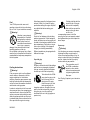
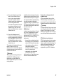
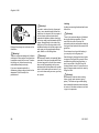
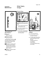
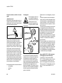
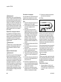
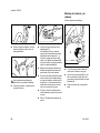
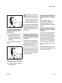
Proper Clothing
!Warning!
To reduce the risk of injury, the operator
should wear proper protective apparel.
Clothing must be sturdy
and snug-fitting, but allow
complete freedom of
movement. Wear long
pants made of heavy
material to help protect
your legs from contact with branches or
brush. To reduce the risk of cut injuries,
wear pants or chaps that contain pads of
cut retardant material.
Avoid loose-fitting jackets, scarfs,
neckties, jewelry, flared or cuffed pants,
unconfined long hair or anything that
could become caught on branches,
brush or the moving parts of the unit.
Secure hair so it is above shoulder level.
Good footing is very
important. Wear sturdy
boots with nonslip soles.
Steel-toed safety boots
are recommended.
7
English / USA
Wear an approved safety
hard hat to reduce the risk
of injury to your head.
Chainsaw noise may
damage your hearing.
Wear sound barriers (ear
plugs or ear mufflers) to help protect
your hearing. Continual and regular
users should have their hearing checked
regularly.
Be particularly alert and cautious when
wearing hearing protection because
your ability to hear warnings (shouts,
alarms, etc.) is restricted.
Never operate your power tool unless
wearing goggles or properly fitted
protective glasses with adequate top
and side protection complying with ANSI
Z 87.1 (or your applicable national
standard). To reduce the risk of injury to
your face STIHL recommends that you
also wear a face shield or face screen
over your goggles or protective glasses.
Always wear gloves when
handling the machine and
the cutting tool. Heavyduty, nonslip gloves
improve your grip and
help to protect your
hands.
STIHL offers a wide range of protective
clothing and equipment.
8
THE POWER TOOL
THE USE OF THE POWER TOOL
For illustrations and definitions of the
power tool parts see the chapter on
“Main Parts and Controls.”
Transporting the Power Tool
!Warning!
To reduce the risk of injury from saw
chain contact, never carry or transport
your power tool with the saw chain
moving. Always engage the chain brake
when taking more than a few steps.
Never modify this power tool in any way.
Only attachments supplied by STIHL or
expressly approved by STIHL for use
with the specific STIHL model are
authorized. Although certain
unauthorized attachments are useable
with STIHL power tools, their use may, in
fact, be extremely dangerous.
If this tool is subjected to unusually high
loads for which it was not designed (e.g.
heavy impact or a fall), always check
that it is in good condition before
continuing work. Check in particular that
the fuel system is tight (no leaks) and
that the controls and safety devices are
working properly. Do not continue
operating this machine if it is damaged.
In case of doubt, have it checked by your
STIHL servicing dealer.
!Warning!
!Warning!
Always switch off the engine, and fit the
chain guard (scabbard) over the chain
and guide bar before transporting the
power tool over longer distances. When
transporting it in a vehicle, properly
secure it to prevent turnover, fuel
spillage and damage to the unit.
001BA115 KN
!Warning!
It may be carried only in a horizontal
position. Grip the front handle in a
manner that the machine is balanced
horizontally. Keep the hot muffler away
from your body and the cutting
attachment behind you.
MS 280 C
English / USA
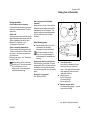
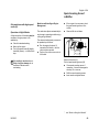
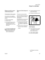
Fuel
Your STIHL power tool uses an oilgasoline mixture for fuel (see the chapter on “Fuel” of your instruction manual).
!Warning!
Gasoline is an extremely
flammable fuel. If spilled
and ignited by a spark or
other ignition source, it
can cause fire and serious
burn injury or property
damage. Use extreme caution when
handling gasoline or fuel mix.
Do not smoke or bring any fire or flame
near the fuel or the power tool. Note that
combustible fuel vapor may escape from
the fuel system.
Select bare ground for fueling and move
at least 10 feet (3 m) from the fueling
spot before starting the engine. Wipe off
any spilled fuel before starting your
machine.
!Warning!
Check for fuel leakage while refueling
and during operation. If fuel leakage is
found, do not start or run the engine until
the leak is fixed and any spilled fuel has
been wiped away. Take care not to get
fuel on your clothing. If this happens,
change your clothing immediately.
Different models may be equipped with
different fuel caps.
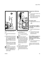
Cap with grip
!Warning!
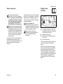
Fueling Instructions
!Warning!
Fuel your power tool in well-ventilated
areas, outdoors. Always shut off the
engine and allow it to cool before
refueling. Gasoline vapor pressure may
build up inside the fuel tank depending
on the fuel used, the weather conditions
and the tank venting system.
In order to reduce the risk of burns and
other personal injury from escaping gas
vapor and fumes, remove the fuel filler
cap on your power tool carefully so as to
allow any pressure build-up in the tank
to release slowly. Never remove the fuel
filler cap while the engine is running.
MS 280 C
In order to reduce the risk of fuel spillage
and fire from an improperly tightened
fuel cap, correctly position and tighten
the fuel cap in the fuel tank opening.
To do this with this STIHL
cap, raise the grip on the
top of the cap until it is
upright at a 90° angle.
Insert the cap in the fuel
tank opening with the
triangular marks on the grip of the cap
and on the fuel tank opening lining up.
Using the grip, turn the cap firmly
clockwise as far as it will go (approx. a
quarter turn).
Fold the grip flush with the
top of the cap. If the grip
does not lie completely
flush with the cap and the
detent on the grip does
not fit in the
corresponding recess in the filler
opening, the cap is not properly seated
and tightened and you must repeat the
above steps.
Screw cap
!Warning!
Unit vibrations can cause an improperly
tightened fuel filler cap to loosen or
come off and spill quantities of fuel. In
order to reduce the risk of fuel spillage
and fire, tighten the fuel filler cap by
hand as securely as possible.
The screwdriver end of
the STIHL combination
wrench or other similar
tool can be used as an aid
in tightening slotted fuel
filler caps.
See "Fueling" chapter in your instruction
manual.
9
English / USA
Before Starting
Take off the chain guard (scabbard) and
inspect the saw for proper condition and
operation. (See the maintenance chart
near the end of the instruction manual.)
!Warning!
Always check your power tool for proper
condition and operation before starting,
particularly the throttle trigger, throttle
trigger interlock, stop switch and cutting
tool. The throttle trigger must move
freely and always spring back to the idle
position. Never attempt to modify the
controls or safety devices.
!Warning!
Never operate your power tool if it is
damaged, improperly adjusted or
maintained, or not completely or
securely assembled.
!Warning!
Check that the spark plug boot is secure
– a loose boot may cause arcing that
could ignite combustible fumes and
cause a fire.
!Warning!
Proper tension of the chain is extremely
important. In order to avoid improper
setting, the tensioning procedure must
be followed as described in your
manual. Always make sure the
hexagonal nut(s) for the sprocket cover
is (are) tightened securely after
tensioning the chain in order to secure
the bar. Never start the saw with the
sprocket cover loose. Check chain
tension once more after having
tightened the nut(s) and thereafter at
regular intervals (whenever the saw is
shut off). If the chain becomes loose
while cutting, shut off the engine and
then tighten. Never try to adjust the
chain while the engine is running!
Keep the handles clean and dry at all
times; it is particularly important to keep
them free of moisture, pitch, oil, fuel mix,
grease or resin in order for you to
maintain a firm grip and properly control
your power tool.
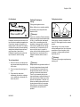
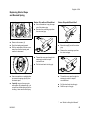
Starting
!Warning!
To reduce the risk of fire and burn
injuries, start the engine at least 10 feet
(3 meters) from the fueling spot,
outdoors only.
Start and operate your saw without
assistance. For specific starting
instructions, see the appropriate section
of the instruction manual. Proper starting
methods reduce the risk of injury.
!Warning
To reduce the risk of injury from chain
contact and/or reactive forces, the chain
brake must be engaged when starting
the saw.
!Warning
Do not drop start. This method is very
dangerous because you may lose
control of the saw.
There are two recommended methods
for starting your chainsaw.
For proper assembly of the bar and
chain follow the procedure described in
the chapter "Mounting the Bar and
Chain" of your instruction manual.
STIHL Oilomatic chain, guide bar and
sprocket must match each other in
gauge and pitch. Before replacing any
bar and chain, see the sections on
"Specifications," "Kickback" and the
"ANSI B 175.1-2000 chainsaw kickback
standard" in the instruction manual.
10
MS 280 C
English / USA
001BA113 KN
001BA114 KN
forces). Never attempt to start the
chainsaw when the guide bar is in a cut
or kerf.
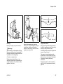
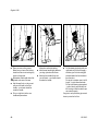
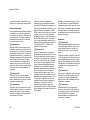
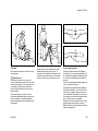
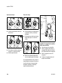
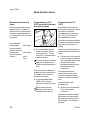
With the first recommended method,
the chainsaw is started on the ground.
Make sure the chain brake is engaged
(see "Chain Brake" chapter in your
instruction manual) and place the
chainsaw on firm ground or other solid
surface in an open area. Maintain good
balance and secure footing.
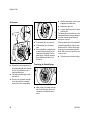
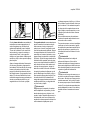
The second recommended method for
starting your chainsaw allows you to
start the saw without placing it on the
ground. Make sure the chain brake is
engaged. Grip the front handle of the
chainsaw firmly with your left hand, keep
your left arm in a locked (straight)
position. Hold the rear handle of the saw
tightly between your legs just above the
knees. If you are using the rear-handleactivated chain brake, be careful not to
disengage the brake by depressing the
interlock lever with your leg. Maintain
good balance and secure footing. Pull
the starting grip slowly with your right
hand until you feel a definite resistance
and then give it a brisk, strong pull.
Grip the front handlebar of the saw firmly
with your left hand and press down. For
saws with a rear handle level with the
ground, put the toe of your right foot into
the rear handle and press down. With
your right hand pull out the starter grip
slowly until you feel a definite resistance
and then give it a brisk, strong pull.
As soon as the engine is running,
immediately blip the throttle trigger,
which will disengage the starting throttle
lock and allow the engine to settle down
to idle.
!Warning!
As soon as you press down the interlock
lever, the rear-handle-activated chain
brake is disengaged and allows the
chain to run at high speed until you blip
the throttle trigger.
!Warning!
When you pull the starter grip, do not
wrap the starter rope around your hand.
Do not let the grip snap back, but guide
the starter rope to rewind it properly.
Failure to follow this procedure may
result in injury to your hand or fingers
and may damage the starter
mechanism.
!Warning!
Be sure that the guide bar and chain are
clear of you and all other obstructions
and objects, including the ground. When
the engine is started, the engine speed
with the starting throttle lock engaged
will be fast enough for the clutch to
engage the sprocket and, if the chain
brake is not activated, turn the chain. If
the upper quadrant of the tip of the bar
touches any object, it may cause kickback to occur (see section on reactive
MS 280 C
11
English / USA
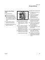
Important Adjustments
!Warning!
To reduce the risk of personal injury from
loss of control or contact with the
running cutting tool, do not use your unit
with incorrect idle adjustment. At correct
idle speed, the cutting tool should not
move. For directions on how to adjust
idle speed, see the appropriate section
of your instruction manual.
If you cannot set the correct idle speed,
have your STIHL dealer check your
power tool and make proper
adjustments and repairs.
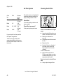
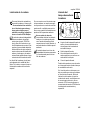
During Operation
Holding and controlling the power
tool
!Warning!
To reduce the risk
of serious or fatal
injury to the
operator or
bystanders from
loss of control, never use the saw with
one hand. It is more difficult for you to
control reactive forces and to prevent
the bar and chain from skating or
bouncing along the limb or log. Even for
those compact saws designed for use in
confined spaces, one-handed operation
is dangerous because the operator may
lose control.
!Warning!
Keep proper footing and balance at all
times. Special care must be taken in
slippery conditions (wet ground, snow)
and in difficult, overgrown terrain. Watch
for hidden obstacles such as tree
stumps, roots, rocks, holes and ditches
to avoid stumbling. There is increased
danger of slipping on freshly debarked
logs. For better footing, clear away fallen
branches, scrub and cuttings. Be
extremely cautious when working on
slopes or uneven ground.
!Warning!
Take extreme care in wet and freezing
weather (rain, snow, ice). Put off the
work when the weather is windy, stormy
or rainfall is heavy.
!Warning!
To reduce the risk of cut injuries, keep
hands and feet away from the cutting
tool. Never touch a moving cutting tool
with your hand or any other part of your
body.
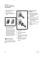
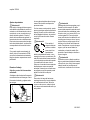
001BA087 LÄ
Always hold the unit firmly with both
hands on the handles while you are
working. Wrap your fingers and thumbs
around the handles.
Your right hand should grip the rear
handle. This also applies to left-handers.
With your hands in this position, you can
best oppose and absorb the push, pull
and kickback forces of your saw without
losing control (see section on reactive
forces).
12
MS 280 C
English / USA
001BA082 KN
!Warning!
001BA031 KN
Position the chainsaw in such a way that
your body is clear of the cutting
attachment whenever the engine is
running. Stand to the left of cut while
bucking.
!Warning
To reduce the risk of injury from loss of
control, never work on a ladder or any
other insecure support. Never hold the
machine above shoulder height. Do not
overreach.
!Warning!
Never work in a tree unless you have
received specific, professional training
for such work, are properly secured
(such as tackle and harness system or a
lift bucket), have both hands free for
operating the chainsaw in a cramped
environment and have taken proper
precautions to avoid injury from falling
limbs or branches.
MS 280 C
Never put pressure on the saw when
reaching the end of a cut. The pressure
may cause the bar and rotating chain to
pop out of the cut or kerf, go out of
control and strike the operator or some
other object. If the rotating chain strikes
some other object, a reactive force may
cause the moving chain to strike the
operator.
Working conditions
Operate and start your power tool only
outdoors in a well ventilated area.
Operate it under good visibility and
daylight conditions only. Work carefully.
Even though bystanders should be kept
away from the running saw, never work
alone. Keep within calling distance of
others in case help is needed.
!Warning!
As soon as the engine is
running, this product
generates toxic exhaust
fumes containing
chemicals, such as
unburned hydrocarbons
(including benzene) and carbon
monoxide, that are known to cause
respiratory problems, cancer, birth
defects, or other reproductive harm.
Some of the gases (e.g. carbon
monoxide) may be colorless and
odorless. To reduce the risk of serious or
fatal injury/illness from inhaling toxic
fumes, never run the machine indoors or
in poorly ventilated locations. If exhaust
fumes become concentrated due to
insufficient ventilation, clear
obstructions from work area to permit
proper ventilation before proceeding
and/or take frequent breaks to allow
fumes to dissipate before they become
concentrated.
!Warning
Your chainsaw is a one-person machine.
Do not allow other persons in the
general work area, even when starting.
Stop the engine immediately if you are
approached.
13
English / USA
!Warning!
!Warning!
!Warning
Inhalation of certain dusts, especially
organic dusts such as mold or pollen,
can cause susceptible persons to have
an allergic or asthmatic reaction.
Substantial or repeated inhalation of
dust and other airborne contaminants, in
particular those with a smaller particle
size, may cause respiratory or other
illnesses. This includes wood dust,
especially from hardwoods, but also
from some softwoods such as Western
Red Cedar. Control dust at the source
where possible. Use good work
practices, such as always cutting with a
properly sharpened chain (which
produces wood chips rather than fine
dust) and operating the unit so that the
wind or operating process directs any
dust raised by the power tool away from
the operator. Follow the
recommendations of EPA/OSHA/
NIOSH and occupational and trade
associations with respect to dust
(“particulate matter”). When the
inhalation of dust cannot be substantially
controlled, i.e., kept at or near the
ambient (background) level, the
operator and any bystanders should
wear a respirator approved by NIOSH/
MSHA for the type of dust encountered.
Breathing asbestos dust is dangerous
and can cause severe or fatal injury,
respiratory illness or cancer. The use
and disposal of asbestos-containing
products have been strictly regulated by
OSHA and the Environmental Protection
Agency. If you have any reason to
believe that you might be cutting
asbestos, immediately contact your
employer or a local OSHA
representative.
The saw chain continues to move for a
short period after the throttle trigger is
released (flywheel effect).
Operating instructions
! Warning!
14
!Warning!
Do not operate your power tool using the
starting throttle lock, as you do not have
control of the engine speed.
In the event of an emergency, switch off
the engine immediately – move the slide
control / stop switch to 0 or STOP.
!Warning!
Accelerating the engine while the saw
chain is blocked increases the load and
will cause the clutch to slip continuously.
This may occur if the throttle is
depressed for more than a few seconds
when the chain is pinched in the cut or
the chain brake is engaged. It can result
in overheating and damage to important
components (e.g. clutch, polymer
housing components) – which can then
increase the risk of injury, e.g., from the
saw chain moving while the engine is
idling.
Your chainsaw is equipped with a chain
catcher. It is designed to reduce the risk
of personal injury in the event of a
thrown or broken chain. From time to
time, the catcher may be damaged or
removed. To reduce the risk of personal
injury, do not operate a chainsaw with a
damaged or missing chain catcher.
Always stop the engine before putting a
chainsaw down.
MS 280 C
English / USA
! Warning!
!Warning!
!Warning!
Inspect buffers periodically. Replace
damaged, broken or excessively worn
buffers immediately, since they may
result in loss of control of the saw. A
"sponginess" in the feel of the saw,
increased vibration or increased
"bottoming" during normal operation
may indicate damage, breakage or
excessive wear. Buffers should always
be replaced in sets. If you have any
questions as to whether the buffers
should be replaced, consult your STIHL
servicing dealer.
To reduce the risk of fire and burn injury,
keep the area around the muffler clean.
Remove excess lubricant and all debris
such as pine needles, branches or
leaves. Let the engine cool down sitting
on concrete, metal, bare ground or solid
wood (e.g. the trunk of a felled tree)
away from any combustible substances.
Since a muffler with a catalytic converter
cools down less rapidly than conventional mufflers, always set your power
tool down in the upright position and
never locate it where the muffler is near
dry brush, grass, wood chips or other
combustible materials while it is still hot.
!Warning!
Your saw is not designed for prying or
shoveling away limbs, roots or other
objects. Such use could damage the
cutting attachment or AV system.
!Warning!
Never modify your muffler. A modified or
damaged muffler could cause an
increase in heat radiation or sparks,
thereby increasing the risk of fire and
burn injury. You may also permanently
damage the engine. Have your muffler
serviced and repaired by your STIHL
servicing dealer only.
!Warning!
When sawing, make sure that the saw
chain does not touch any foreign
materials such as rocks, fences, nails
and the like. Such objects may be flung
off, damage the saw chain or cause the
saw to kickback.
!Warning!
The muffler and other parts of the engine
(e.g. fins of the cylinder, spark plug)
become hot during operation and remain
hot for a while after stopping the engine.
To reduce risk of burns do not touch the
muffler and other parts while they are
hot.
MS 280 C
Catalytic converter
!Warning!
Some STIHL power tools
are equipped with a
catalytic converter, which
is designed to reduce the
exhaust emissions of the
engine by a chemical
process in the muffler. Due to this
process, the muffler does not cool down
as rapidly as conventional mufflers when
the engine returns to idle or is shut off.
To reduce the risk of fire and burn
injuries, the following specific safety
precautions must be observed.
!Warning!
An improperly mounted or damaged
shroud or a damaged/deformed muffler
shell may interfere with the cooling
process of the catalytic converter. To
reduce the risk of fire or burn injury, do
not continue work with a damaged or
improperly mounted cylinder shroud or a
damaged/deformed muffler shell.
Your catalytic converter is furnished with
screens designed to reduce the risk of
fire from the emission of hot particles.
Due to the heat from the catalytic
reaction, these screens will normally
stay clean and need no service or
maintenance. If you experience loss of
performance and you suspect a clogged
screen, have your muffler maintained by
a STIHL servicing dealer.
15
English / USA
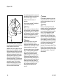
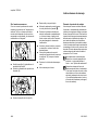
Kickback:
Reactive forces including kickback
!Warning!
The greater the force of the kickback
reaction, the more difficult it becomes for
the operator to control the saw. Many
factors influence the occurrence and
force of the kickback reaction. These
include chain speed, the speed at which
the bar and chain contact the object, the
angle of contact, the condition of the
chain and other factors.
The powerful force used to cut wood can
be reversed and work against the
operator. If the rotating chain is suddenly
stopped by contact with any solid object
such as a log or branch or is pinched, the
reactive forces may occur instantly.
These reactive forces may result in loss
of control, which, in turn, may cause
serious or fatal injury. An understanding
of the causes of these reactive forces
may help you avoid the element of
surprise and loss of control. Sudden
surprise contributes to accidents.
The most common reactive forces are:
–
kickback,
–
pushback,
–
pull-in.
16
001BA035 KN
001BA093 LÄ
Reactive forces may occur any time the
chain is rotating. Reactive forces can
cause serious personal injury.
Kickback may occur when
the moving saw chain
near the upper quadrant
of the bar nose contacts a
solid object or is pinched.
Kickback may occur, for example,
when the chain near the upper quadrant
of the bar nose contacts the wood or is
pinched during limbing or when it is
incorrectly used to begin a plunge or
boring cut.
The reaction of the cutting force of the
chain causes a rotational force on the
chainsaw in the direction opposite to the
chain movement. This may fling the bar
up and back in a ligtening fast reaction in
an uncontrolled arc mainly in the plane
of the bar. Under some cutting
circumstances the bar moves towards
the operator, who may suffer severe or
fatal injury.
The type of bar and saw chain you use
is an important factor in the occurrence
and force of the kickback reaction. Some
STIHL bar and chain types are designed
to reduce kickback forces. STIHL
recommends the use of reduced
kickback bars and low kickback chains.
ANSI B 175.1-2000 chainsaw
kickback standard
Section 5.11 of ANSI standard
B 175.1-2000, sets certain performance
and design criteria related to chainsaw
kickback.
To comply with section 5.11 of ANSI
B 175.1-2000:
MS 280 C
English / USA
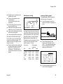
a) Saws with a displacement of less
than 3.8 cubic inches (62 cm³)
–
must, in their original condition,
meet a 45° computer derived
kickback angle when equipped with
certain cutting attachments,
–
and must be equipped with at least
two devices to reduce the risk of
kickback injury, such as a chain
brake, low kickback chain, reduced
kickback bar, etc.
b) Saws with a displacement of
3.8 cubic inches (62 cm³) and above
–
must be equipped with at least one
device designed to reduce the risk
of kickback injury such as a chain
brake, low kickback chain, reduced
kickback bar, etc.
The computer derived angles for saws
below 3.8 cubic inch (62 cm³)
displacement are measured by applying
a computer program to test results from
a kickback test machine.
!Warning!
The computer derived angles of § 5.11
of ANSI B 175.1-2000 may bear no
relationship to actual kickback bar
rotation angles that may occur in real life
cutting situations.
MS 280 C
In addition, features designed to reduce
kickback injuries may lose some of their
effectiveness when they are no longer in
their original condition, especially if they
have been improperly maintained.
Compliance with § 5.11 of ANSI B 175.12000 does not automatically mean that
in a real life kickback the bar and chain
will rotate at most 45°.
!Warning!
In order for powerheads below 3.8 cubic
inch (62 cm³) displacement to comply
with the computed kickback angle
requirements of § 5.11 of ANSI B 175.12000 use only the following cutting
attachments:
–
bar and chain combinations listed
as complying in the "Specifications"
section of the instruction manual or
–
other replacement bar and chain
combinations marked in
accordance with the standard for
use on the powerhead or
–
replacement chain designated
"low kickback saw chain.“
Devices for reducing the risk of
kickback injury
STIHL recommends the use of the
STIHL Quickstop chain brake on your
powerhead with green labeled reduced
kickback bars and low kickback chains.
!Warning!
To reduce the risk of injury, never use a
saw if the chain brake does not function
properly. Take the saw to your local
STIHL servicing dealer. Do not use the
saw until the problem has been rectified.
STIHL Quickstop chain brake
STIHL has developed a chain stopping
system designed to reduce the risk of
injury in certain kickback situations. It is
called a Quickstop chain brake. The
Quickstop chain brake is standard
equipment on your STIHL chainsaw.
See the section on "Low kickback saw
chain and reduced kickback bars."
17
English / USA
On models equipped with a rear-handleactivated chain brake the interlock lever
and the throttle trigger on the rear
handle act as a third means of
activation.
See the chapter entitled "Chain Brake"
of your instruction manual.
001BA174 KN
!Warning!
When a kickback occurs, the guide bar
may rotate around the front handle. If the
cutting position is such that the
operator's left hand is gripping the front
handle behind the hand guard, and if the
left hand rotates around the front handle
and makes a sufficiently forceful contact
with the front hand guard, which is the
Quickstop activating lever, this contact
will activate a properly maintained
Quickstop chain brake. The chain brake
on newer STIHL chainsaws can also be
activated by inertia. If the kickback
forces are sufficiently high, the hand
guard is accelerated towards the bar
nose even without hand contact.
18
Never operate your chainsaw without a
front hand guard. In a kickback situation
this guard helps protect your left hand
and other parts of your body. In addition,
removal of the hand guard on a saw
equipped with a Quickstop chain brake
will deactivate the chain brake.
!Warning!
No Quickstop or other chain brake
device prevents kickback. These
devices are designed to reduce the risk
of kickback injury, if activated, in certain
kickback situations. In order for the
Quickstop to reduce the risk of kickback
injury, it must be properly maintained
and in good working order. See the
chapter of your instruction manual
entitled "Chain Brake" and the section
"Maintenance, Repair and Storing" at
the end of these Safety Precautions. In
addition, there must be enough distance
between the bar and the operator to
ensure that the Quickstop has sufficient
time to activate and stop the chain
before potential contact with the
operator.
!Warning!
An improperly maintained chain brake
may increase the time needed to stop
the chain after activation, or may not
activate at all.
!Warning!
Never run the chainsaw above idle
speed for more than 3 seconds when the
chain brake is engaged or when the
chain is pinched or otherwise caught in
the cut. Clutch slippage can cause
excessive heat, leading to severe
damage of the motor housing, clutch
and oiler component and may interfere
with the operation of the chain brake. If
clutch slippage in excess of 3 seconds
has occurred, allow the motor housing to
cool before proceeding and check the
operation of your chain brake as
described in the chapter entitled "Chain
Brake" of your instruction manual. Also
make sure that the chain is not turning at
idle speed (see above at "Important
Adjustments").
MS 280 C
English / USA
Low kickback saw chain and reduced
kickback bars
STIHL offers a variety of bars and
chains. STIHL reduced kickback bars
and low kickback chains are designed to
reduce the risk of kickback injury. Other
chains are designed to obtain higher
cutting efficiency or sharpening ease but
may result in higher kickback tendency.
STIHL has developed a color code
system to help you identify the STIHL
reduced kickback bars and low kickback
chains. Cutting attachments with green
warning decals or green labels on the
packaging are designed to reduce the
risk of kickback injury. The matching of
green decaled powerheads under 3.8
cubic inch (62 cm³) displacement with
green labeled bars and green labeled
chains gives compliance with the
computed kickback angle requirements
of ANSI B 175.1-2000 when the
products are in their original condition.
Products with yellow decals or labels are
for users with extraordinary cutting
needs and experience and specialized
training for dealing with kickback.
STIHL recommends the use of its
green labeled reduced kickback bars,
green labeled low kickback chains
and a STIHL Quickstop chain brake
for both experienced and
inexperienced chainsaw users.
MS 280 C
Please ask your STIHL dealer to
properly match your powerhead with the
appropriate bar/chain combination to
reduce the risk of kickback injury. Green
labeled bars and chains are
recommended for all powerheads.
Warning!
Use of other, non-listed bar/chain
combinations may increase kickback
forces and the risk of kickback injury.
New bar/chain combinations may be
developed after publication of this
literature, which will, in combination with
certain powerheads, comply with
§ 5.11 of ANSI B 175.1-2000. Check
with your STIHL dealer for such
combinations.
Low kickback chain
Some types of saw chain have specially
designed components to reduce the
force of nose contact kickback. STIHL
has developed low kickback chain for
your powerhead.
"Low kickback saw chain" is a chain
which has met the kickback
performance requirements of § 5.11.2.4
of ANSI B 175.1-2000 (GasolinePowered Chain Saws–Safety
Requirements) when tested in its
original condition on a selected
representative sample of chainsaws
below 3.8 cubic inch (62 cm³)
displacement specified in
ANSI B 175.1-2000.
!Warning!
!Warning!
Reduced kickback bars and low
kickback chains do not prevent
kickback, but they are designed to
reduce the risk of kickback injury. They
are available from your STIHL dealer.
There are potential powerhead and bar
combinations with which low kickback
saw chains can be used which have not
been specifically certified to comply with
the 45° computer derived kickback
angle of § 5.11 of ANSI B 175.1-2000.
Some low kickback chains have not
been tested with all powerhead and bar
combinations.
!Warning!
Even if your saw is equipped with a
Quickstop, a reduced kickback bar and/
or low kickback chain, this does not
eliminate the risk of injury by kickback.
Therefore, always observe all safety
precautions to avoid kickback situations.
!Warning!
A dull or improperly sharpened chain
may reduce or negate the effects of the
design features intended to reduce
kickback energy. Improper lowering or
sharpening of the depth gauges or
shaping of the cutters may increase the
chance and the potential energy of a
kickback. Always cut with a properly
sharpened chain.
19
English / USA
To avoid kickback
STIHL green labeled reduced kickback
bars are designed to reduce the risk of
kickback injury when used with STIHL
green labeled low kickback chains.
The best protection from personal injury
that may result from kickback is to avoid
kickback situations:
!Warning!
When used with other, more aggressive
chains, these bars may be less effective
in reducing kickback.
1.
Hold the chainsaw firmly with both
hands and maintain a secure grip.
Don’t let go.
2.
Be aware of the location of the guide
bar nose at all times.
3.
Never let the nose of the guide bar
contact any object. Do not cut limbs
with the nose of the guide bar. Be
especially careful near wire fences
and when cutting small, tough
limbs, small size brush and saplings
which may easily catch the chain.
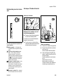
Bow Guides
!Warning!
Do not mount a bow guide on any STIHL
chainsaw. Any chainsaw equipped with
a bow guide is potentially very
dangerous. The risk of kickback is
increased with a bow guide because of
the increased kickback contact area.
Low kickback chain will not significantly
reduce the risk of kickback injury when
used on a bow guide.
4
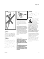
Don't overreach.
A
Pull-in occurs when the chain on the
bottom of the bar is suddenly stopped
when it is pinched, caught or encounters
a foreign object in the wood. The
reaction of the chain pulls the saw
forward and may cause the operator to
lose control.
Pull-in frequently occurs when the
bumper spike of the saw is not held
securely against the tree or limb and
when the chain is not rotating at full
speed before it contacts the wood.
5.
Don't cut above shoulder height.
6.
Begin cutting and continue at full
throttle.
7.
Cut only one log at a time.
8.
Use extreme caution when
reentering a previous cut.
!Warning!
Do not attempt to plunge cut if you
are not experienced with these
cutting techniques.
Use extreme caution when cutting small
size brush and saplings which may
easily catch the chain, be whipped
towards you or pull you off balance.
9.
10. Be alert for shifting of the log or
other forces that may cause the cut
to close and pinch the chain.
11. Maintain saw chain properly. Cut
with a correctly sharpened, properly
tensioned chain at all times.
12. Stand to the side of the cutting path
of the chainsaw.
20
A = Pull-in
001BA037 KN
Reduced kickback bars
To avoid pull-in
1.
Always start a cut with the chain
rotating at full speed and the
bumper spike in contact with the
wood.
2.
The risk of pull-in may also be
reduced by using wedges to open
the kerf or cut.
MS 280 C
English / USA
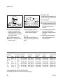
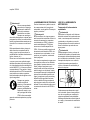
Cutting Techniques
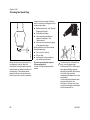
B = Pushback
Felling Instructions:
Felling
Pushback occurs when the chain on the
top of the bar is suddenly stopped when
it is pinched, caught or encounters a
foreign object in the wood. The reaction
of the chain may drive the saw rapidely
straight back toward the operator and
may cause loss of saw control.
Pushback frequently occurs when the
top of the bar is used for cutting.
To avoid pushback
1.
Be alert to forces or situations that
may cause material to pinch the top
of the chain.
2.
Do not cut more than one log at a
time.
3.
Do not twist the saw when
withdrawing the bar from a plunge
cut or underbuck cut because the
chain can pinch.
MS 280 C
Before felling a tree, consider carefully
all conditions which may affect the
direction of fall.
!Warning!
There are a number of factors that may
affect and change the intended direction
of fall, e.g. wind direction and speed,
lean of tree, surrounding trees and
obstacles, sloping ground, one-sided
limb structure, wood structure, decay,
snow load, etc. To reduce the risk of
severe or fatal injury to yourself or
others, look for these conditions prior to
beginning the cut, and be alert for a
change in direction while the tree is
falling.
!Warning!
1
1/ 2
21/2
1
001BA088 LÄ
B
001BA038 KN
Felling is cutting down a tree.
When felling, maintain a distance of at
least 21/2 tree lengths from the nearest
person.
When felling in the vicinity of roads,
railways and power lines, etc., take extra
precautions. Inform the police, utility
company or railway authority before
beginning to cut.
!Warning!
The noise of your engine may drown any
warning call.
Always observe the general condition of
the tree. Inexperienced users should
never attempt to cut trees which are
decayed or rotted inside or which are
leaning or otherwise under tension.
There is an increased risk that such
trees could snap or split while being cut
and cause serious or fatal injury to the
operator or bystanders. Also look for
broken or dead branches which could
vibrate loose and fall on the operator.
When felling on a slope, the operator
should stand on the uphill side if
possible.
21
English / USA
B
Buttress roots
C
001BA146 KN
45°
A
45°
C
001BA143 KN
B
001BA040 KN
If the tree has large buttress roots, cut
into the largest buttress vertically first
(horizontally next) and remove the
resulting piece.
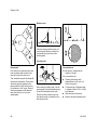
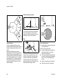
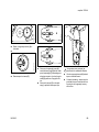
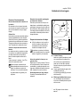
Gunning sight
Conventional cut
First clear the tree base and work area
from interfering limbs and brush and
clean its lower portion with an ax.
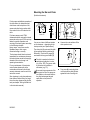
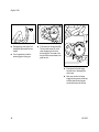
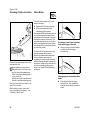
C = felling notch - determines the
direction of the fall
Then, establish two paths of escape (B)
and remove all obstacles. These paths
should be generally opposite to the
planned direction of the fall of the tree
(A) and about at a 45° angle. Place all
tools and equipment a safe distance
away from the tree, but not on the
escape paths.
22
001BA153 KN
Escape path
For a conventional cut:
:
Properly place felling notch
perpendicular to the line of fall,
close to the ground.
When making the felling notch, use the
gunning sight on the shroud and housing
to check the desired direction of fall:
:
Cut down at app. 45-degree angle
to a depth of about 1/5 to 1/4 of the
trunk diameter.
Position the saw so that the gunning
sight points exactly in the direction you
want the tree to fall.
:
Make second cut horizontal.
:
Remove resulting 45-degree piece.
MS 280 C
English / USA
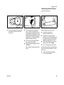
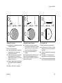
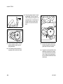
C
D
C
001BA144 KN
001BA150 KN
001BA143 KN
D
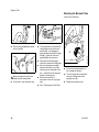
Open-face technique
Making sapwood cuts
D = Felling cut
C = felling notch - determines the
direction of the fall
:
Conventional and open-face technique:
For an open-face cut:
:
Properly place felling notch
perpendicular to the line of fall,
close to the ground.
:
Cut down at app. 50-degree angle
to a depth of app.1/5 to 1/4 of the
trunk diameter.
:
Make second cut from below at app.
40 degree angle.
:
Remove resulting 90-degree piece.
MS 280 C
:
For medium sized or larger trees
make cuts at both sides of the trunk,
at same height as subsequent
felling cut.
Cut to no more than width of guide
bar.
This is especially important in softwood
in summer - it helps prevent sapwood
splintering when the tree falls.
:
Begin 1 to 2 inches (2,5 to 5 cm)
higher than center of felling notch.
:
Cut horizontally towards the felling
notch.
:
Leave approx.1/10 of diameter
uncut. This is the hinge.
:
Do not cut through the hinge - you
could lose control of the direction of
the fall.
23
English / USA
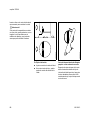
Drive wedges into the felling cut where
necessary to control the fall.
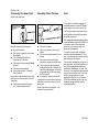
E
!Warning!
If the tip of the bar contacts a wedge, it
may cause kickback. Wedges should be
of wood or plastic - never steel, which
can damage the chain.
001BA145 KN
001BA147 KN
E
E = Hinge
24
:
Helps control the falling tree.
:
Do not cut through the hinge – you
could lose control of the direction of
the fall.
Felling cut for small diameter trees:
simple fan cut
Engage the bumper spikes of the
chainsaw directly behind the location of
the intended hinge and pivot the saw
around this point only as far as the
hinge. The bumper spike rolls against
the trunk.
MS 280 C
English / USA
Plunge-cut method
Timber having a diameter more than
twice the length of the guide bar requires
the use of the plunge-cut method before
making the felling cut.
First, cut a large, wide felling notch.
Make a plunge cut in the center of the
notch.
2
1
001BA148 KN
4
Felling cut for large diameter trees:
!Warning!
Felling a tree that has a diameter greater
than the length of the guide bar requires
use of either the sectioning felling cut or
plunge-cut method. These methods are
extremely dangerous because they
involve the use of the nose of the guide
bar and can result in kickback. Only
properly trained professionals should
attempt these techniques.
Avoid repositioning the saw more than
necessary. When repositioning for the
next cut, keep the guide bar fully
engaged in the kerf to keep the felling
cut straight. If the saw begins to pinch,
insert a wedge to open the cut. On the
last cut, do not cut the hinge.
The plunge cut is made with the guide
bar nose. Begin the plunge cut by
applying the lower portion of the guide
bar nose to the tree at an angle. Cut until
the depth of the kerf is about the same
as the width of the guide bar. Next, align
the saw in the direction in which the
recess is to be cut.
With the saw at full throttle, insert the
guide bar in the trunk.
Sectioning method
For the sectioning method make the first
part of the felling cut with the guide bar
fanning in toward the hinge. Then, using
the bumper spike as a pivot, reposition
the saw for the next cut.
MS 280 C
25
English / USA
!Warning!
Enlarge the plunge cut as shown in the
illustration.
!Warning!
There is an extreme danger of kickback
at this point. Extra caution must be taken
to maintain control of the saw. To make
the felling cut, follow the sectioning
method described previously.
If you are inexperienced with a
chainsaw, plunge-cutting should not be
attempted. Seek the help of a
professional.
In order to reduce the risk of personal
injury, never stand directly behind the
tree when it is about to fall, since part of
the trunk may split and come back
towards the operator (barber-chairing),
or the tree may jump backwards off the
stump. Always keep to the side of the
falling tree. When the tree starts to fall,
withdraw the bar, shut off the engine and
walk away on the preplanned escape
path. Watch out for falling limbs.
!Warning!
Be extremely careful with partially fallen
trees which are poorly supported. When
the tree hangs or for some other reason
does not fall completely, set the saw
aside and pull the tree down with a cable
winch, block and tackle or tractor. If you
try to cut it down with your saw, you may
be injured.
Limbing
Limbing is removing the branches from a
fallen tree.
!Warning!
There is an extreme danger of kickback
during the limbing operation. Do not
work with the nose of the bar. Be
extremely cautious and avoid contacting
the log or other limbs with the nose of the
guide bar.
Do not stand on a log while limbing it you may slip or the log may roll.
Start limbing by leaving the lower limbs
to support the log off the ground. When
underbucking freely hanging limbs, a
pinch may result or the limb may fall,
causing loss of control. If a pinch occurs,
stop the engine and remove the saw by
lifting the limb.
!Warning!
Be extremely cautious when cutting
limbs or logs under tension (spring
poles). The limbs or logs could spring
back toward the operator and cause loss
of control of the saw and severe or fatal
injury to the operator.
26
MS 280 C
English / USA
2
001BA151 KN
1
Bucking
Bucking is cutting a log into sections.
!Warning!
When bucking, do not stand on the log.
Make sure the log will not roll downhill. If
on a slope, stand on the uphill side of the
log. Watch out for rolling logs.
Cut only one log at a time.
Shattered wood should be cut very
carefully. Sharp slivers of wood may be
caught and flung in the direction of the
operator of the saw.
MS 280 C
When cutting small logs, place log
through "V" - shaped supports on top of
a sawhorse. Never permit another
person to hold the log. Never hold the
log with your leg or foot.
1
001BA152 KN
001BA051 LÄ
001BA033 KN
2
Logs under strain:
Risk of pinching! Always start relieving
cut (1) at compression side.Then make
bucking cut (2) at tension side.
If the saw pinches, stop the engine and
remove it from the log.
Only properly trained professionals
should work in an area where the logs,
limbs and roots are tangled. Working in
“blow down“ areas is extremely
hazardous.
Drag the logs into a clear area before
cutting. Pull out exposed and cleared
logs first.
27
English / USA
MAINTENANCE, REPAIR AND
STORING
Maintenance, replacement, or repair
of the emission control devices and
systems may be performed by any
nonroad engine repair establishment
or individual. However, if you make a
warranty claim for a component
which has not been serviced or
maintained properly or if
nonapproved replacement parts were
used, STIHL may deny coverage.
!Warning!
Use only identical STIHL replacement
parts for maintenance and repair. Use of
non-STIHL parts may cause serious or
fatal injury.
Strictly follow the maintenance and
repair instructions in the maintenance
chart near the end of the instruction
manual.
!Warning!
Always stop the engine and make sure
that the chain is stopped before doing
any maintenance or repair work or
cleaning the power tool.
!Warning!
!Warning!
Do not attempt any maintenance or
repair work not described in your
instruction manual. Have such work
performed by your STIHL servicing
dealer only. For example, if improper
tools are used to remove the flywheel or
if an improper tool is used to hold the
flywheel in order to remove the clutch,
structural damage to the flywheel could
occur and could subsequently cause the
flywheel to burst.
Do not operate your chainsaw if the
muffler is damaged, missing or modified.
An improperly maintained muffler will
increase the risk of fire and hearing loss.
Wear gloves when handling or
performing maintenance on saw chains.
!Warning!
Use the specified spark plug and make
sure it and the ignition lead are always
clean and in good condition. Always
press spark plug boot snugly onto spark
plug terminal of the proper size. (Note: If
terminal has detachable SAE adapter
nut, it must be securely attached.) A
loose connection between spark plug
terminal and the ignition wire connector
in the boot may create arcing that could
ignite combustible fumes and cause a
fire.
!Warning!
Never test the ignition system with the
spark plug boot removed from the spark
plug or with a removed spark plug, since
uncontained sparking may cause a fire.
28
If your muffler was equipped with a
spark-arresting screen to reduce the risk
of fire, never operate your saw if the
screen is missing or damaged.
Remember that the risk of forest fires is
greater in hot or dry weather.
Keep the chain, bar and sprocket clean;
replace worn sprockets or chains. Keep
the chain sharp. You can spot a dull
chain when easy-to-cut wood becomes
hard to cut and burn marks appear on
the wood. Keep the chain at proper
tension.
Tighten all nuts, bolts and screws except
the carburetor adjustment screws after
each use.
!Warning!
In order for the chain brake on your
STIHL chainsaw to properly perform its
function of reducing the risk of kickback
and other injuries, it must be properly
maintained. Like an automobile brake, a
chainsaw chain brake incurs wear each
time it is engaged.
The amount of wear will vary depending
upon usage, conditions under which the
saw is used and other factors. Excessive
wear will reduce the effectiveness of the
chain brake and can render it
inoperable.
MS 280 C
English / USA
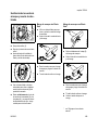
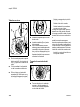
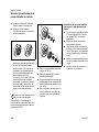
Mounting the Bar and Chain
(Side chain tensioner)
The chainsaw should also be returned
immediately for maintenance whenever
the brake system cannot be thoroughly
cleaned or there is a change in its
operating characteristics.
For any maintenance of the emission
control system please refer to the
maintenance chart and to the limited
warranty statement near the end of the
instruction manual.
Store chainsaw in a dry place and away
from children. Before storing for longer
than a few days, always empty the fuel
tank (see chapter "Storing the Machine"
in the instruction manual).
MS 280 C
2
3
You can run chains of different pitches
on this chainsaw – depending on the
chain sprocket (see “Specifications”):
143BA034 KN
a
t=a:2
:
Unscrew the nuts and take off the
chain sprocket cover.
The chain pitch (1) must match the pitch
of the sprocket and the guide bar (for
Rollomatic). The drive link gauge (2)
must match the bar groove width (3).
4
5
The pitch is marked on the chain
sprocket and guide bar in inches
(e.g. 3/8 or .325). The groove width
is marked on the guide bar in
millimeters (e.g. 1.6).
If non-matching components of the
wrong pitch or drive link gauge are
run together on the same machine
they may be damaged beyond
repair after a short period of
operation.
:
001BA107 KN
For these reasons, each STIHL
chainsaw should be returned to trained
personnel such as your STIHL servicing
dealer for periodic inspection and
servicing of the brake system according
to the following schedule:
Heavy usage - every three months,
Moderate usage - twice a year,
Occasional usage - annually.
1
001BA105 KN
For the proper and effective operation of
the chain brake, the brake band and
clutch drum must be kept free of dirt,
grease and other foreign matter which
may reduce friction of the band on the
drum.
Turn screw (4) counterclockwise
until the tensioner slide (5) butts
against left end of housing slot.
29
English / USA
Mounting the Bar and Chain
(Quick Chain Tensioner)
6
Wear work gloves to protect your
hands from the sharp cutters.
:
:
Press down the throttle trigger
interlock to release the chain brake.
:
Now turn tensioning screw (10)
clockwise until there is very little
chain sag on the underside of the
bar –- and the drive link tangs are
located in the bar groove.
:
Fit the chain – start at the bar nose.
1
Fit the guide bar over the studs (7) –
cutting edges on top of bar must
point to right – and engage the
peg of the tensioner slide in locating
hole (8) –- place the chain over
sprocket (9) at the same time.
Refit the sprocket cover –
and screw on the nuts only fingertight.
3
2
133BA026 KN
:
:
30
7
8 10
001BA108 KN
Pull the hand guard (6) back toward
the front handle.
143BA003 KN
:
7
001BA109 KN
9
:
Pull out the hinged handle (1) so
that it snaps into position.
:
Turn the wingnut (2) counterclockwise until it hangs loose in the
sprocket cover (3).
:
Remove the sprocket cover.
Go to “Tensioning the Saw Chain”.
MS 280 C
English / USA
4
4
:
Remove the tensioning gear (4) and
turn it over.
8
:
Position the tensioning gear (4)
against the guide bar (6) so that the
stud (7) projects through the upper
hole and the short guide peg (8)
locates in the lower hole.
5
133BA028 KN
4
5
133BA030 KN
:
Unscrew the nut (5).
:
MS 280 C
133BA031 KN
133BA027 KN
6
133BA029 KN
7
Screw the nut (5) on to the stud as
far as stop.
Wear work gloves to protect your
hands from the sharp cutters.
:
Turn the tensioning gear (4)
clockwise as far as stop.
:
Fit the chain – start at the bar nose.
Pay attention to the position of the
tensioning gear and the cutting
edges.
31
English / USA
11
9
Disengage the chain brake: Pull
hand guard (9) towards the front
handle.
:
Turn the guide bar so that the
tensioning gear is facing you.
32
:
Fit the chain over the sprocket (10).
The long collar screw (11) in the
center engages the hole in the
tensioning gear. The heads of the
two short collar screws locate in the
guide bar slot.
133BA034 KN
:
133BA033 KN
133BA032 KN
10
:
Press down the throttle trigger
interlock lever to disengage the
chain brake.
:
Make sure the drive link tangs
engage the bar groove (see arrow)
and then rotate tensioning gear
counterclockwise as far as stop.
MS 280 C
English / USA
Tensioning the Saw Chain
(Side chain tensioner)
12
11
133BA036 KN
133BA035 KN
:
Fit the chain sprocket cover so that
the wingnut locates on the collar
screw (11).
1
:
When fitting the chain sprocket
cover, check that the teeth of the
tensioning gear and adjusting wheel
mesh properly. If necessary, turn the
adjusting wheel (12) slightly until the
sprocket cover can be pushed flush
against the engine housing.
Retensioning during cutting work:
:
Shut off the engine first –
and then loosen the nuts.
:
Hold the bar nose up and use
screwdriver to turn tensioning screw
(1) clockwise until chain fits snugly
against the underside of the bar.
:
Pull out the hinged handle (13) so
that it snaps into position.
:
:
Engage wingnut and tighten it down
moderately.
While still holding the bar nose up,
tighten down the nuts firmly.
:
Go to “Tensioning the Saw Chain”
Go to chapter "Tensioning the Saw
Chain".
A new chain has to be retensioned more
often than one that has been in use for
some time.
:
MS 280 C
133BA024 KN
13
Check chain tension frequently –
see "During Operation".
33
English / USA
Tensioning the Saw Chain
Checking Chain Tension
Fuel
(Quick chain tensioner)
This engine is certified to operate on
unleaded gasoline and the STIHL twostroke engine oil at a mix ratio of 50:1.
143BA007 KN
2
001BA112 KN
1
Retensioning during cutting work:
:
Shut off the engine.
:
Shut off the engine.
:
:
Pull out the hinged clip and loosen
the wingnut.
Wear work gloves to protect your
hands.
:
:
Turn the adjusting wheel (1)
clockwise as far as stop.
Pull the hand guard toward the rear
handle.
:
:
Tighten down the wingnut (2) firmly
by hand.
Press down the throttle trigger
interlock to release the chain brake.
:
:
Fold down the hinged clip.
:
Follow instructions in "Checking
Chain Tension".
Chain must fit snugly against the
underside of the bar – and, with the
chain brake disengaged, it must still
be possible to pull the chain along
the bar by hand.
:
If necessary, retension the chain.
A new chain has to be retensioned more
often than one that has been in use for
some time.
:
34
Check chain tension frequently –
see "Operating Instructions".
A new chain has to be retensioned more
often than one that has been in use for
some time.
Your engine requires a mixture of highquality gasoline and quality two-stroke
air cooled engine oil.
Use mid-grade unleaded gasoline with a
minimum octane rating of 89 (R+M/2). If
the octane rating of the mid-grade
gasoline in your area is lower, use
premium unleaded fuel.
Fuel with a lower octane rating may
increase engine temperatures. This, in
turn, increases the risk of piston seizure
and damage to the engine.
The chemical composition of the fuel is
also important. Some fuel additives not
only detrimentally affect elastomers
(carburetor diaphragms, oil seals, fuel
lines, etc.), but magnesium castings and
catalytic converters as well. This could
cause running problems or even
damage the engine. For this reason
STIHL recommends that you use only
nationally recognized high-quality
unleaded gasoline!
Check chain tension frequently – see
chapter "During Operation".
MS 280 C
English / USA
Fueling
We recommend STIHL 50:1 two-stroke
engine oil since it is specially formulated
for use in STlHL engines.
Do not use BIA or TCW rated (twostroke water cooled) mix oils or other
mix oils that state they are for use in both
water cooled and air cooled engines
(e.g., outboard motors, snowmobiles,
chainsaws, mopeds, etc.).
Take care when handling gasoline.
Avoid direct contact with the skin and
avoid inhaling fuel vapor. When filling at
the pump, first remove the canister from
your vehicle and place the canister on
the ground before filling. Do not fill fuel
canisters that are sitting in or on a
vehicle.
The canister should be kept tightly
closed in order to avoid any moisture
getting into the mixture.
Fuel mix ages
Only mix sufficient fuel for a few days
work, not to exceed 3 months of storage.
Store in approved fuel-canisters only.
When mixing, pour oil into the canister
first, and then add gasoline. Close the
canister and shake it vigorously by hand
to ensure proper mixing of the oil with
the fuel.
001BA159 KN
Use only STIHL two-stroke engine oil or
equivalent high-quality two-stroke
engine oils that are designed for use
only in air cooled two-cycle engines.
Gasoline
Oil (STIHL 50:1 or
equivalent high-quality oils)
Before fueling, clean the filler cap and
the area around it to ensure that no dirt
falls into the tank.
US gal.
1
2 1/2
5
US fl.oz
2.6
6.4
12.8
Always position the machine so that the
filler cap points upwards.
Dispose of empty mixing-oil canisters
only at authorized disposal locations.
Always thoroughly shake the mixture in
the canister before fueling your
machine.
In order to reduce the risk of burns
or other personal injury from
escaping gas vapor and fumes,
remove the fuel filler cap carefully
so as to allow any pressure build-up
in the tank to release slowly.
The machine‘s fuel tank and the canister
in which fuel mix is stored should be
cleaned as necessary.
MS 280 C
35
English / USA
Closing the cap
:
Fit the cap - grip upright -marks
must line up.
:
Turn the cap clockwise as far as
stop (approx. a quarter turn).
165BA003 KN
Raise the grip until it is upright.
001BA161 KN
:
001BA162 KN
001BA160 KN
Opening the cap
Turn the cap counterclockwise
(approx. a quarter turn).
:
Remove the filler cap.
:
001BA163 KN
:
Change the fuel pickup body
once every year
:
Drain the fuel tank.
:
Use a hook to pull the fuel pickup
body out of the tank and take it off
the hose.
Fold the grip flush with the top of the
cap.
:
Push the new pickup body into the
hose.
:
Place the pickup body in the tank.
If the grip does not lie completely flush
with the cap and the detent on the grip
does not engage the recess in the filler
neck, the cap is not properly seated and
tightened and you must repeat the
above steps.
36
MS 280 C
English / USA
Chain Lubricant
Biological chain oil must be resistant
to aging (e.g. STIHL BioPlus) since
it will otherwise quickly turn to resin.
This results in hard deposits that are
difficult to remove, especially in the
area of the chain drive, clutch and
chain. It may even cause the oil
pump to seize.
The service life of the chain and guide
bar depends on the quality of the
lubricant. It is therefore essential to use
only a specially formulated chain
lubricant.
If special chain lubricant is not available,
you may – in an emergency – use an HD
single grade or multigrade engine oil
with a viscosity that suits the prevailing
outside temperature.
Do not use waste oil!
Medical studies have shown that
renewed contact with waste oil can
cause skin cancer. Moreover, waste
is environmentally harmful!
Waste oil does not have the
necessary lubricating properties
and is unsuitable for chain
lubrication.
001BA158 KN
For automatic and reliable
lubrication of the chain and guide
bar – use only an environmentally
compatible quality chain and bar
lubricant with non-fling additive
or the rapidly biodegradable
STIHL BioPlus is recommended.
Filling Chain
Oil Tank
:
Thoroughly clean the oil filler cap
and the area round it to ensure that
no dirt falls into the tank.
:
Remove the filler cap.
:
Refill the chain oil tank every time
you refuel.
:
Close the filler cap.
There must still be a small amount of oil
in the oil tank when the fuel tank is
empty.
If the oil level in the tank does not go
down, the reason may be a problem in
the oil supply system: Check chain
lubrication, clean the oilways, contact
your servicing dealer for assistance if
necessary. STIHL recommends that you
have maintenance and repair work
performed only by a STIHL servicing
dealer.
MS 280 C
37
English / USA
Checking Chain Lubrication
Chain Brake
The chain brake system on your saw
has two functions:
:
:
Standard STIHL chain brake and
STIHL rear-handle-activated
secondary braking system
143BA024 KN
The standard STIHL chain brake utilizes
the front hand guard as the activating
mechanism and is designed to stop the
chain within fractions of a second. The
secondary braking system, on the other
hand, is designed to stop chain rotation
within a second of you completely letting
go of the rear handle.
The saw chain must always throw off a
small amount of oil.
Never operate your saw without
chain lubrication. If the chain runs
dry, the whole cutting attachment
will be irretrievably damaged within
a very short time.
Always check chain lubrication and
oil level in tank before starting work.
Every new chain has to be broken in for
about 2 to 3 minutes.
After breaking in chain, check chain
tension and adjust if necessary – see
“Checking Chain Tension”.
38
Secondary chain brake activated
by throttle trigger interlock
:
To reduce the risk of personal injury or
property damage during cutting,
observe the characteristics that make
this saw different from saws not
equipped with a rear-handle-activated
brake. Before operating the chainsaw for
the first time, make sure you are familiar
with how secondary braking system
works. See chapter "Starting/Stopping
the Engine".
When you let go of the rear handle,
including the throttle trigger
interlock lever.
Disengaging the secondary chain
brake
:
Press down the throttle trigger
interlock lever. This releases the
clutch drum and allows the chain to
rotate.
MS 280 C
English / USA
Always disengage chain brake
before accelerating engine and
before starting cutting work. The
only exception to this rule is when
you check operation of the chain
brake.
Standard chain brake is activated
by front hand guard
:
When the hand guard is pushed
toward the bar nose by the left hand
or by inertia in certain kickback
situations.
The chain is brought to a standstill and
locked in position.
High revs with the chain brake engaged
(chain locked) will quickly damage the
powerhead and chain drive (clutch,
chain brake).
The chain brake is designed to be
activated also by the inertia of the
front hand guard
if the forces are sufficiently high. The
hand guard is accelerated toward the
bar nose – even if your left hand is not
behind the hand guard, e.g. during a
felling cut. The chain brake will operate
only if it has been properly maintained
and the hand guard has not been
modified in any way.
Check operation of rear-handleactivated chain brake
Before starting work:
Open the throttle fully and then release
the rear handle. The chain must stop
moving within less than a second.
Check operation of hand-guardactivated chain brake
Before starting work: Run engine at idle
speed, engage the chain brake (push
hand guard toward bar nose). Open the
throttle wide for no more than 3 seconds.
The chain must not rotate. The hand
guard must be free from dirt and move
freely.
In case of any doubt about the above
functions, contact your STIHL dealer for
assistance.
Disengaging the chain brake
:
Pull the hand guard toward the front
handle.
MS 280 C
39
English / USA
Winter Operation
The chain brake is subject to normal
wear and tear. It must therefore be
checked and serviced regularly by
trained personnel (e.g. STIHL dealer) at
the following intervals:
Full-time professional
usage:
At temperatures below +50 °F
(+10 °C), preheat carburetor as
follows:
every 3
months
Semi-professional
usage (farm and
construction industry): every 6
months
Hobby and occasional
usage:
every 12
months
1
:
At temperatures below +14 °F
(-10 °C):
It is advisable to fit the cover plate
(special accessory) on the fan cover in
extremely cold conditions (temperatures
below -10 °C, in powder or drifting
snow).
146BA000 KN
Chain brake maintenance
Use a suitable screwdriver to turn
the shutter (1) from the summer
position (s) to the winter position
(r) – the shutter must snap into
position.
If the carburetor box cover is
removed, the shutter can be turned
to the required position by hand.
Heated air is now drawn in from around
the cylinder and mixed with cold air –
this helps prevent carburetror icing.
:
40
At temperatures above +68 °F
(+20 °C): Turn the shutter back to
the summer position (s).
This is essential to avoid engine
running problems and overheating.
The cover plate partially blanks off the
slots in the fan cover to help prevent
snow being sucked into the machine.
When the cover plate is fitted, the
shutter must be in the winter position.
:
If your saw is very cold (frost or ice
on machine), start the engine and
keep it at a high idle speed (with
chain brake disengaged) until it
reaches normal operating
temperature.
In the event of engine running problems,
first check that conditions for use of the
cover plate still apply.
If engine idle speed is erratic or
acceleration is poor
:
Turn low speed screw (L) 1/4 turn
counterclockwise.
It is usually necessary to change the
setting of the idle speed screw (LA)
after making adjustments to the the low
speed screw (L) – see “Adjusting the
Carburetor”.
MS 280 C
English / USA
Starting / Stopping
the Engine
Information
Before You Start
Starting the Engine
STOP
STOP
0
146BA001 KN
1
Only Models with Decompression
Valve
001BA140 KN
:
3
The valve closes automatically as soon
as the engine begins to fire.
:
The four positions of the
Master Control lever
2
Press in the button (arrow) to open
the decompression valve.
For this reason the decompression
valve should be pressed in before
each starting attempt.
146BA002 KN
0
All Models
:
Observe safety precautions.
$ = Engine off –
ignition is switched off.
:
Push hand guard (1) forward:
The chain is now locked.
# = Normal run position –
engine runs or can fire.
:
Press down trigger interlock (2) and
squeeze throttle trigger (3) at the
same time.
Set Master Control lever to:
for cold start l
for warm start n
(even if engine has been running
but is still cold)
To move the Master Control lever from #
to n or l, press down the throttle
trigger interlock and squeeze throttle
trigger at the same time.
n=Warm start – this position is used to
start a warm engine. The Master
Control lever moves to the normal
run position as soon as the throttle
trigger is squeezed.
l=Cold start – this position is used to
start a cold engine.
MS 280 C
41
:
Place your saw on the ground.
Make sure you have a firm footing –
check that chain is not touching any
object or the ground.
Bystanders must be well clear of the
general work area of the saw.
:
Hold the saw firmly on the ground
with your left hand on the front
handle – your thumb should be
under the handle.
:
Put your right foot into the rear
handle and press down.
42
:
:
Alternative method of starting:
Hold the rear handle tightly between
your legs, just above the knees.
Hold the front handle firmly with
your left hand – your thumb should
be under the handle.
146BA005 KN
146BA003 KN
146BA004 KN
English / USA
:
Pull the starter grip slowly with your
right hand until you feel it engage –
and then give it a brisk strong pull
and push down the front handle at
the same time.
Do not pull out starter rope to its full
length – it might otherwise break.
Do not let the starter grip snap back
– guide it slowly and vertically into
the housing so that the starter rope
can rewind properly.
If engine is new, pull starter grip several
times to prime the fuel line.
MS 280 C
English / USA
At very low outside temperatures:
:
Allow engine to warm up at part
throttle.
:
Change over to winter operation if
necessary – see “Winter
Operation”.
STOP
0
6
To shut down the engine:
:
If fuel tank has been run until dry
and then refueled:
When engine begins to fire:
:
Press in decompression valve.
:
Move Master Control lever (4) to n
and continue cranking – as soon
as engine runs, immediately blip
the throttle trigger (5) –
the Master Control lever (4) will
move to the “Run” position # (6)
and the engine will settle down to
idling speed.
As the chain brake is still engaged,
the engine must be returned to
idling speed immediately – or the
engine and chain brake might
otherwise be damaged.
MS 280 C
150BA007 KN
5
146BA006 KN
4
.
Move Master Control lever to $
:
Pull the hand guard back toward
the front handle:=
The chain brake is now disengaged
– your saw is ready for operation.
Always disengage chain brake
before accelerating engine. High
revs with the chain brake engaged
(chain locked) will quickly damage
the powerhead and chain drive
(clutch, chain brake).
:
Observe safety precautions.
:
Always check operation of chain
lubrication before starting work.
:
Press in decompression valve.
:
Start as described for warm engine
(warm start n).
If fuel tank has been run
completely dry (engine stops)
and then refueled:
:
Press in button to open the
decompression valve.
Start as described for cold engine (cold
start l).
43
English / USA
Operating Instructions
If the engine doesn’t start:
:
Unscrew and dry off the spark plug.
During break-in period
If you did not move the Master Control
lever to “Warm Start” n quickly enough
after the engine began to fire, the
combustion chamber has flooded.
:
Set the Master Control lever to
“Stop” position $
:
Press down the interlock lever, open
the throttle wide and, at the same
time, crank the engine several times
with the starter to clear the
combustion chamber.
:
Refit the spark plug and connect the
spark plug boot –
reassemble the other parts.
A factory new machine should not be run
at high revs (full throttle off load) for the
first three tank fillings. This avoids
unnecessary high loads during the
break-in period. As all moving parts
have to bed in during the break-in
period, the frictional resistances in the
engine are greater during this period.
The engine develops its maximum
power after about 5 to 15 tank fillings.
:
Set Master Control lever to “Warm
Start” n – even if engine is cold.
:
Press in decompression valve.
:
Now start the engine.
2
:
Loosen knob (1) in direction of
arrow.
:
Remove the carburetor box
cover (2).
146BA010 KN
1
Do not make the mixture leaner to
achieve an apparent increase in
power – this could damage the
engine – see “Adjusting
Carburetor”.
Always disengage the chain brake
before opening the throttle. Running
the engine at higher revs with the
chain brake engaged (saw chain at
a standstill) will quickly damage the
engine and chain drive (clutch,
chain brake).
146BA009 KN
3
:
44
Pull off the spark plug boot (3).
MS 280 C
English / USA
Taking Care of Guide Bar
Check chain tension frequently
A new chain has to be retensioned more
often than one that has been in use for
some time.
Chain cold:
Tension is correct when chain fits snugly
against the underside of the bar and can
still be pulled along the bar by hand.
Retension if necessary – see
“Tensioning the Saw Chain”.
Chain at operating temperature:
The chain stretches and begins to sag.
The drive links must not come out of the
bar groove – the chain may otherwise
jump off the bar.
Retension the chain – see “Tensioning
the Saw Chain”!
Always slacken off the chain after
finishing work. The chain contracts
as it cools down. If it is not
slackened off, it can damage the
crankshaft and bearings.
After long period of full-throttle
operation
Allow engine to run for a short while at
idle speed so that engine heat can be
dissipated by flow of cooling air. This
protects engine-mounted components
(ignition, carburetor) from thermal
overload.
2
After finishing work
:
3
Slacken off the chain if you have
retensioned it at operating
temperature during cutting work.
The chain contracts as it cools
down. If it is not slackened off, it
could damage the crankshaft and
bearings.
Storing your saw for a short period:
Wait for engine to cool down. To avoid
condensation, fill the fuel tank and keep
the machine in a dry place, well away
from sources of ignition, until you need it
again.
Storing for a long period:
See “Storing the Unit”!
1
:
Turn the bar over –
every time you sharpen the chain
and every time you replace the
chain – this helps avoid one-sided
wear, especially at the nose and
underside of the bar.
:
Regularly clean
the oil inlet hole (1),
the oilway (2) and
the bar groove (3).
:
Measure groove depth –
with scale on filing gauge* – in area
used most for cutting.
*
MS 280 C
3
001BA119 KN
During operation
see “Guide to Using this Manual”
45
English / USA
Air Filter System
Picco
Rapid
Rapid
Rapid
Pitch
Minimum
groove
depth
3/8“ P
0.20"
(5.0 mm)
1/4“
0.16"
(4.0 mm)
3/8“; 0.325“ 0.24"
(6.0 mm)
0.404“
0.28"
(7.0 mm)
The air filter system can be adapted to
suit different operating conditions by
simply installing a choice of filters.
1
Fabric filter*
For normal operating conditions and
winter operation.
2
Fleece filter (non-woven)*
For dry and very dusty work areas.
If there is a noticeable loss of engine
power
:
Loosen the knob (1) above the rear
handle in the direction of the arrow.
:
Remove the carburetor box
cover (2).
:
Clean away loose dirt from around
the filter.
:
Remove the filter.
:
Knock the filter out on the palm of
your hand or blow it clear with
compressed air from the inside
outwards.
If groove depth is less than specified:
:
146BA010 KN
Chain
type
Cleaning the Air Filter
Replace the guide bar.
The drive link tangs will otherwise
scrape along the bottom of the groove –
the cutters and tie straps will not ride on
the bar rails.
In case of stubborn dirt:
:
Wash the filter components in
STIHL universal cleaner or a clean,
non-flammable solution (e.g. warm
soapy water) and then dry.
Do not use a brush to clean the fleece
filter.
:
*
46
Always replace damaged filters.
see “Guide to Using this Manual“
MS 280 C
English / USA
146BA011 KN
3
:
Locate the filter (3) in position (see
arrows).
:
Fit the carburetor box cover.
Motor Management
Adjusting the Carburetor
Exhaust emissions are controlled by the
design of the fundamental engine
parameters and components (e.g.
carburation, ignition, timing and valve or
port timing) without the addition of any
major hardware.
Your chainsaw is equipped with one of
the following carburetors:
L
LA
–
Intelligent Engine Management –
Carburetor without high speed
screw (H). Full load range and
maximum RPM are controlled
electronically.
L
146BA014 KN
H
–
MS 280 C
Carburetor with high speed
screw (H)
47
English / USA
Standard Setting
H
Adjusting Idle Speed
L
Erratic idling behavior, poor
acceleration
L
:
Shut off the engine.
Engine stops while idling
:
Check the air filter and clean or
replace if necessary.
:
Check the standard setting at the
low speed screw (L).
:
Check spark arresting screen* in the
muffler and clean or replace it as
necessary.
:
Turn the idle speed screw (LA)
clockwise until chain begins to run –
then back it off one turn.
Turn low speed screw (L) clockwise as
far as stop. Then back it off one quarter
turn.
Only machines with high speed
screw (H)
Turn the high speed screw (H)
counterclockwise (max. 3/4 turn) as far
as stop.
*
48
146BA014 KN
LA
:
Check the standard setting at the
low speed screw (L).
:
Turn the idle speed screw (LA)
counterclockwise until chain stops
running – then turn screw another
turn in the same direction.
If the chain continues moving when
the engine is idling, have your saw
checked and repaired by your
servicing dealer.
Check the standard setting at the
low speed screw (L).
Idle setting too lean:
:
Chain runs when engine is idling
:
L
146BA013 KN
146BA012 KN
H
Turn low speed screw (L)
counterclockwise until the engine
runs and accelerates smoothly –
no further than stop.
It is usually necessary to change the
setting of the idle speed screw (LA)
after every correction to the low speed
screw (L).
Machines with Intelligent Engine
Management
:
Run the engine for about 10
seconds at full throttle – with the
chain and bar mounted.
:
Perform cross cut at full throttle.
See "Guide to Using this Manual"
MS 280 C
English / USA
Spark Arresting Screen*
in Muffler
Only machines with high speed
screw (H)
Machines with Intelligent Engine
Management
:
If the engine is low on power, check
the spark arresting screen in the
muffler.
Operation at High Altitude
The carburetor adjusts automatically to
any change in operating conditions (e.g.
cutting at high altitude).
:
Allow muffler to cool down.
:
Check the standard setting.
:
Warm up the engine.
:
Turn high speed screw (H) slightly
clockwise (leaner) – no further than
stop.
If the setting is too lean there is
a risk of engine damage due to
insufficient lubrication and
overheating.
MS 280 C
The automatic adjustment process can
be speeded up as follows:
:
Run the engine for about 10
seconds at full throttle – with the
chain and bar mounted.
:
Perform five uniform cross cuts at
full throttle.
2
1
146BA008 KN
A slight correction of the setting may be
necessary if engine power is not
satisfactory:
Remove the screw (1).
Pull out spark arresting screen (2).
:
Clean spark arresting screen if
necessary – if screen is damaged or
coked up, fit a new one.
:
Refit the spark arresting screen.
:
Insert screw and tighten down.
*
see “Guide to Using this Manual”
49
English / USA
Checking the Spark Plug
If engine is down on power, difficult to
start or runs poorly at idling speed, first
check the spark plug.
Remove spark plug – see "Starting /
Stopping the Engine".
:
Clean dirty spark plug.
:
Check electrode gap (A) and
readjust if necessary – see
"Specifications".
:
Use only resistor type spark plugs
of the approved range.
000BA002 KN
Rectify problems which have caused
fouling of spark plug:
Wrong fuel mix (too much engine oil in
the gasoline), a dirty air filter and
unfavorable running conditions (mostly
at part throttle etc.) affect the condition of
the spark plug. These factors cause
deposits to form on the insulator nose
which may result in trouble in operation.
50
:
Too much oil in fuel mix.
:
Dirty air filter.
:
Unfavorable running conditions,
e.g. operating at part load.
Fit a new spark plug after approx.
100 operating hours
or earlier if the electrodes are badly
eroded.
1
000BA036 TR
:
To reduce the risk of fire and burn
injury, use only spark plugs
authorized by STIHL. Always press
spark plug boot (2) snugly onto
spark plug terminal (1) of the proper
size. (Note: If terminal has
detachable SAE adapter nut, it must
be attached.)
A loose connection between spark
plug boot and ignition wire
connector in the boot may create
arcing that could ignite combustible
fumes and cause a fire.
MS 280 C
English / USA
Replacing Starter Rope
and Rewind Spring
1
:
Remove the remaining rope from
the rotor and grip.
146BA017 KN
1
Use a screwdriver to pry the rope
out of the starter grip.
1
:
Remove the screws (1).
:
Push the hand guard upward.
:
Pull the underside of the fan cover
away from the fan housing and
remove it downward.
2
5
146BA020 KN
1
:
:
Thread the new rope through the
starter grip and tie a simple
overhand knot.
:
Pull the knot back into the grip.
3
4
001BA096 KN
4
:
Use a screwdriver or suitable pliers
to remove the spring clip (2) from
the starter post.
:
Carefully remove the rope rotor
with washer (3) and pawls (4) – do
not pull the rewind spring out of the
housing – take care to avoid injury.
:
Ease the cap (5) out of the starter
grip.
:
Remove the remaining rope from
the rotor and grip.
:
Thread the new rope through the
starter grip and tie a simple
overhand knot.
:
Pull the knot back into the grip.
:
Refit the cap in the grip.
146BA018 KN
1
Starter Grip with ElastoStart*
*
MS 280 C
135BA000 KN
Starter Grip without ElastoStart
see “Guide to Using this Manual”
51
English / USA
All Versions
2
3
6
7
:
Fit the pawls (4) in the rope rotor.
:
Fit the washer (3) on the starter
post.
:
Use a screwdriver or suitable pliers
to install the spring clip (2) on the
starter post and engage it on the
pawls’ pegs – the spring clip must
point clockwise as shown in the
illustration.
146BA019 KN
8
Thread the rope through the top of
the guide bushing (6), pull it through
the rotor (7) and secure it with a
simple overhand knot.
:
Coat rope rotor bearing bore with
resin-free oil.
:
Slip rotor over the starter post (8) –
turn it back and forth to engage
anchor loop of the rewind spring.
:
Release the rope rotor.
:
Let go of rope slowly so that it winds
onto the rotor.
The starter grip must locate firmly in the
rope guide bushing. If the grip droops to
one side: Increase spring tension by
adding one more turn.
When the starter rope is fully extended it
must still be possible to rotate the rotor
another half turn. If this is not the case,
the spring is overtensioned and could
break. Take one turn of rope off the rotor
in such a case.
:
Fit the fan cover on the fan housing.
Tensioning the Rewind Spring
:
52
Hold the rotor steady – pull out and
straighten the twisted rope.
146BA007 KN
:
4
001BA096 KN
4
:
Make a loop in the starter rope and
use it to turn the rope rotor six full
revolutions in the direction of the
arrow.
MS 280 C
English / USA
Storing the Machine
Replacing a Broken Rewind
Spring
:
Drain and clean the fuel tank in a
well ventilated area.
:
Dispose of remaining fuel and
cleaning solution properly in
accordance with local
environmental requirements.
:
Run engine until carburetor is dry,
this helps prevent the carburetor
diaphragms sticking together.
:
Remove the saw chain and guide
bar, clean them and spray with
corrosion inhibiting oil.
:
Thoroughly clean the unit,
pay special attention to the cylinder
fins and air filter.
:
If you use a biological chain and bar
lubricant, e.g. STIHL BioPlus,
completely fill the chain oil tank.
:
Store the unit in a dry and high or
locked location, out of the reach of
children and other unauthorized
persons.
Remove the rope rotor.
The bits of spring might still be
under tension and could fly apart
when you take them out of the fan
cover. To reduce risk of injury, wear
eye and face protection and work
gloves.
:
Use a screwdriver to carefully
remove the parts of the spring.
:
Lubricate the new spring with a few
drops of non-resinous oil.
001BA103 KN
:
For periods of about 3 months or longer:
:
:
:
MS 280 C
Place the replacement spring with
frame in the fan cover – the spring
loop must engage the lug in the fan
cover.
Apply a suitable tool (screwdriver,
punch or similar) to the recesses
(arrows) and push the spring into its
seat in the fan cover – the spring
slips out of the frame in this process.
Reinstall the rope rotor, tension the
rewind spring, fit the fan cover and
secure in position with the screws.
53
English / USA
Checking and Replacing
Chain Sprocket
:
Remove the chain sprocket cover,
chain and guide bar.
:
Disengage the chain brake:
Pull hand guard toward the front
handle.
Installing spur sprocket /
rim sprocket
5
6
4
–
Replace sooner if the wear marks
on the sprocket are deeper than
approx. 0.02 in (0,5 mm) since this
would reduce the life of the chain.
You can use a gauge (“Special
Accessories”) to check the depth of
the wear marks on sprockets.
It is best to use two chains in
rotation with one sprocket.
Use only original STIHL chain sprockets
to ensure correct operation of the chain
brake.
54
6
2
1
001BA122 KN
001BA121 KN
3
Replace the chain sprocket after
using two Oilomatic chains.
Clean the crankshaft stub and
needle cage, and lubricate with
STlHL grease (“Special
Accessories”).
:
push needle cage on to crankshaft
:
After fitting clutch drum or spur
sprocket, rotate it about one turn to
engage oil pump drive.
:
Fit rim sprocket with cavities facing
outward.
:
Refit washer and E-clip on the
crankshaft.
2
1
–
:
:
Use a screwdriver to remove
the E-clip (1).
:
Take off the washer (2) and rim
sprocket (3).
:
Examine splines on clutch drum (4)
– if wear marks are severe, fit a new
clutch drum.
:
Pull clutch drum or spur sprocket
(5) and needle cage (6) off the
crankshaft.
MS 280 C
English / USA
Maintaining and Sharpening
Saw Chain
Correctly sharpened chain
:
Clean the chain.
:
Check the chain for cracks in the
links and damaged rivets.
:
Replace any damaged or worn parts
of the chain and match the new
parts to the shape and size of the
original parts.
It is absolutely essential to comply
with the angles and dimensions
specified below. If the saw chain is
incorrectly sharpened – and in
particular if the depth gauge is set
too low – there is a risk of increased
kickback of the chainsaw, with
resulting risk of injury.
MS 280 C
3/8
The chain pitch (e.g. 3/8") is marked on
the depth gauge end of each cutter.
Use only special saw chain
sharpening files. Other files have the
wrong shape and cut.
Select file diameter according to chain
pitch – see table “Sharpening Tools”.
You must observe certain angles when
resharpening the chain cutter.
689BA021 KN
Do not work with a dull or damaged
chain as it will increase the physical
effort required, cause high vibrations,
produce unsatisfactory cutting results
and a higher rate of wear.
A
689BA020 KN
A properly sharpened chain slices
through wood effortlessly and requires
very little feed pressure.
B
A = Filing angle
B = Side plate angle
Chain type
Rapid-Micro (RM)
Rapid-Super (RS)
Picco-Micro (PM/PMN)
Angle (°)
A
B
30
85
30
60
30
85
Cutter shapes:
Micro = Semi-chisel
Super = Full chisel
The specified angles A and B are
obtained automatically if the
recommended files or sharpening tools
and correct settings are used.
55
English / USA
For checking angles
80°
30°
35°
:
Use a file holder
A file holder (special accessory) must be
used for manual resharpening (see table
"Sharpening Tools"). The correct filing
angles are marked on the file holder.
56
0°
90°
Use a STlHL filing gauge (special
accessory – see table "Sharpening
Tools"). This is a universal tool for
checking the filing and side plate angles,
depth gauge setting and cutter length. It
also cleans the guide bar groove and oil
inlet holes.
689BA043 KN
689BA025 KN
10°
As these requirements can be met only
after sufficient and constant practice:
Sharpen chain frequently, take
away as little metal as possible –
two or three strokes of the file are
usually enough.
File correctly
:
Select sharpening tools according
to chain pitch.
:
Clamp the bar in a vise if necessary.
:
Lock the chain – push hand guard
forward.
:
To rotate the chain, pull the hand
guard against the front handle to
disengage the chain brake. On
models with QuickStop Super, also
press down the throttle trigger
interlock lever.
689BA018 KN
90°
85° 70° 60°
:
689BA022 KN
Furthermore, the angles must be the
same on all cutters. If angles are
uneven: Chain will run roughly, not in a
straight line, wear quickly and finally
break.
:
Hold the file horizontally (at right
angle to side of guide bar) and file
according to the angles marked on
the file holder. Rest the file holder on
the top plate and depth gauge.
MS 280 C
English / USA
The file only sharpens on the
forward stroke –
lift the file off the cutter on the
backstroke.
:
Avoid touching the tie straps and
drive links with the file.
:
Rotate the file at regular intervals
while filing to avoid one-sided wear.
:
Use a piece of hardwood to remove
burrs from cutting edge.
:
Check angles with the filing gauge.
All cutters must be the same length.
If the cutters are not the same length,
they will have different heights. This
makes the chain run roughly and can
cause it to break.
:
Find the shortest cutter and then file
all other cutters back to the same
length. This can be very time
consuming – it is best to have it
done in the workshop on an electric
grinder.
MS 280 C
Lowering depth gauges
The depth gauge setting is reduced
when the chain is sharpened.
:
a
Use a filing gauge to check the
setting every time you sharpen the
chain.
The depth gauge determines the height
at which the cutter enters the wood and
thus the thickness of the chip removed.
1
Specified distance or setting between
depth gauge and cutting edge = a:
This setting may be increased by 0.2mm
(0.008") for cutting softwood in mild
weather season – no frost.
Chain pitch
Inch
1/
4
3/ PMN
8
3/ PM
8
0.325
3/
8
0.404
689BA047 KN
:
Depth gauge setting
:
Place a filing gauge (1) that
matches the chain pitch on the
chain – if the depth gauge projects
from the filing gauge, the depth
gauge has to be lowered.
:
File down the depth gauge until it is
level with the filing gauge.
Depth gauge
setting “a“
(mm)
mm
(inch)
(6.35) 0.65
(0.026)
(9.32) 0.45
(0.018)
(9.32) 0.65
(0.026)
(8.25) 0.65
(0.026)
(9.32) 0.65
(0.026)
(10.26) 0.80
(0.031)
689BA051 KN
Always file from the inside to the
outside of the cutter.
689BA023 KN
:
57
English / USA
:
File the top of the depth gauge
parallel to the stamped service
marking (see arrow) – but do not
lower the highest point of the depth
gauge in this process.
The kickback tendency of the
chainsaw is increased if the depth
gauges are too low.
The other parts of the triple-humped
tie strap and humped drive link must
not be filed since this may increase
the kickback tendency of the
chainsaw.
689BA052 KN
689BA044 KN
RSC3, RMC3, PMC3:
The upper part of the humped drive link
(with service marking) is lowered along
with the depth gauge.
:
Place filing gauge on the chain –
highest point of depth gauge must
be level with the filing gauge.
PM 1, RM2:
Rear hump of tie strap (with service
marking) is lowered along with the depth
gauge.
Sharpening Tools (special accessories)
Chain pitch
Round file Ø Round file
inch
(mm)
mm (inch)
Part No.
1/
5/ )
(6.35)
4.0
(
5605 772 4006
4
32
3/ PMN
5/ )
(9.32)
4.0
(
5605 772 4006
8
32
3/ P
5/ )
(9.32)
4.0
(
5605 772 4006
8
32
3
0.325
(8.25) 4.8 ( /16)
5605 772 4806
3/
13/ )
(9.32)
5.2
(
5605 772 5206
8
64
5605 772 5506
0.404
(10.26) 5.5 (7/32)
File holder
Part No.
5605 750 4327
5605 750 4327
5605 750 4327
5605 750 4328
5605 750 4329
5605 750 4330
:
After sharpening, clean the chain
thoroughly, remove filings or
grinding dust – lubricate the chain
thoroughly.
:
Before long out-of-service period,
clean the chain and store it in a
well-oiled condition.
Filing gauge
Part No.
1110 893 4000
0000 893 4000
1110 893 4000
1110 893 4000
1110 893 4000
1106 893 4000
Flat file1)
Part No.
0814 252 3356
0814 252 3356
0814 252 3356
0814 252 3356
0814 252 3356
0814 252 3356
Sharpening kit2)
Part No.
5605 007 1027
5605 007 1026
5605 007 1027
5605 007 1028
5605 007 1029
5605 007 1030
1) Use triangular file 0811 421 8971 for PM1 and RM2
2) consisting of file holder with round file, flat file and filing gauge
58
MS 280 C
English / USA
Complete machine
Throttle trigger, trigger interlock, Master
Control
Chain brake
Pickup body/filter in fuel tank
Visual inspection (condition, leaks)
X
Check operation
X
X
Check operation
X
X
Have checked by servicing dealer1)2)
X
Check
X
Clean, replace filter element
X
X
X
X
Clean
Chain oil tank
Clean
Chain lubrication
Check
X
Inspect, also check sharpness
X
X
Check chain tension
X
X
X
X
Sharpen
Guide bar
X
X
Clean and turn over
X
Deburr
X
Replace
Chain sprocket
Air filter
AV elements (rubber buffers, springs)
X
X
Check
X
Clean
X
X
Replace
Inspect
X
X
Fuel tank
Check (wear, damage)
as required
if damaged
if problem
X
X
Clean
Replace pickup body
Saw chain
every 12 months
monthly
weekly
after each
refueling stop
after finishing
work or daily
Please note that the following maintenance intervals apply for normal
operating conditions only. If your daily working time is longer than normal or
cutting conditions are difficult (very dusty work area, resin-rich wood,
tropical wood etc.), shorten the specified intervals accordingly. If you only
use the saw occasionally, extend the intervals accordingly.
before
starting work
Maintenance Chart
X
X
Have replaced by servicing dealer1)
X
Cooling inlets
Clean
X
Cylinder fins
Clean
X
X
1) STIHL recommends that this work
be done by a STIHL servicing dealer
2) see "Chain brake"
MS 280 C
59
Carburetor
Spark plug
All accessible screws and nuts
(not adjusting screws) 2)
Spark arresting screen* in muffler
Chain catcher
Safety label
Check idle adjustment – chain must not rotate
X
as required
if damaged
if problem
every 12 months
monthly
weekly
after each
refueling stop
after finishing
work or daily
Please note that the following maintenance intervals apply for normal
operating conditions only. If your daily working time is longer than normal or
cutting conditions are difficult (very dusty work area, resin-rich wood,
tropical wood etc.), shorten the specified intervals accordingly. If you only
use the saw occasionally, extend the intervals accordingly.
before
starting work
English / USA
X
X
Readjust idle
X
Readjust electrode gap
Replace after about 100 operating hours
X
Retighten
X
Inspect
X
Clean or replace
Check
X
Replace
X
Replace
X
1) STIHL recommends that this work
be done by a STIHL servicing dealer
2) Firmly tighten cylinder base screws
of professional saws (3.4 kW or
more) after 10 to 20 hours of
operation
*
60
see “Guide to Using this Manual“
MS 280 C
English / USA
Main Parts of the Saw
1= Carburetor box cover twist lock
2= Carburetor adjusting screws
3= Spark plug boot
4= Decompression valve*
(automatically resetting)
3
5= Chain sprocket cover
4
1
6= Chain sprocket
#
2
7
11
8
6
7= Chain brake
9
8= Adjusting wheel of quick
tensioner*
9= Side chain tensioner
12
10= Chain catcher
13
10
150BA002 KN
5
11= Bumper spike
12= Guide bar
13= Oilomatic saw chain
#
Machine number
14= Oil filler cap
17
15= Muffler
16= Front hand guard
16
17= Front handle (handlebar)
18= Starter grip
19= Fuel filler cap
18
20= Master Control lever
21= Throttle trigger
22
20
22= Coasting brake activating lever
(Throttle trigger interlock)
23
14
23= Rear handle
21
19
24
150BA003 KN
15
24= Rear hand guard
*
MS 280 C
see "Guide to Using this Manual"
61
English / USA
Definitions
1. Carburetor Box Cover Twist Lock
Lock for carburetor box cover.
2. Carburetor Adjusting Screws
For fine tuning the carburetor.
3. Spark Plug Boot
Connects the spark plug with the
ignition wire.
4. Decompression Valve
(automatically resetting)
Releases compression pressure to
make starting easier when activated.
5. Chain Sprocket Cover
Covers the clutch and the sprocket.
6. Chain Sprocket
The toothed wheel that drives the
saw chain.
7. Chain Brake
A device to stop the rotation of the
chain if activated in a kickback
situation by the operator's hand or
by inertia.
8. Adjusting Wheel
Quick chain tensioner*.
9. Chain Tensioner
Permits precise adjustment of chain
tension.
10. Chain Catcher
Helps to reduce the risk of operator
contact by a chain if it breaks or
comes off the bar.
*
62
see "Guide to Using this Manual"
11. Bumper Spike
Toothed stop for holding saw steady
against wood.
12. Guide Bar
Supports and guides the saw chain.
13. Oilomatic Saw Chain
A loop consisting of cutters, tie
straps and drive links.
14. Oil Filler Cap
For closing the oil tank.
15. Muffler
Reduces engine exhaust noise and
directs the exhaust gases.
16. Front Hand Guard
Provides protection against
projecting branches and helps
prevent left hand from touching the
chain if it slips off the handlebar. It
also serves as the lever for chain
brake activation.
17. Front Handle
Handlebar for the left hand at the
front of the saw.
18. Starter Grip
The grip of the starter, for starting
the engine.
19. Fuel Filler Cap
For closing the fuel tank.
20. Master Control Lever
Lever for choke control, starting
throttle, run and stop switch
positions.
21. Throttle Trigger
Controls the speed of the engine.
22. Coasting Brake Activating Lever
(Throttle Trigger Interlock)
Must be depressed before the
throttle trigger can be activated.
Engages and disengages the
coasting brake.
23. Rear Handle
The support handle for the right
hand, located at or toward the rear
of the saw.
24. Rear Hand Guard
Gives added protection to
operator's right hand.
Guide Bar Nose
The exposed end of the guide bar.
(not illustrated, see chapter
"Tensioning the Saw Chain")
Clutch
Couples engine to chain sprocket
when engine is accelerated beyond
idle speed. (not illustrated)
Anti-Vibration System
The anti-vibration system includes a
number of Anti-Vibration elements
designed to reduce the
transmission of vibrations created
by the engine and cutting
attachment to the operator's hands.
(not illustrated)
MS 280 C
English / USA
Specifications
EPA / CEPA:
The Emission Compliance Period
referred to on the Emissions
Compliance Label indicates the number
of operating hours for which the engine
has been shown to meet Federal
emission requirements.
Category:
A = 300 hours,
B = 125 hours,
C = 50 hours
CARB:
The Emission Compliance Period used
on the CARB-Air Index Label indicates
the terms:
Extended = 300 hours,
Intermediate = 125 hours,
Moderate = 50 hours
Engine
STIHL single cylinder two-stroke engine
Displacement
Bore
Stroke
Idle speed
Weight without
bar and chain
Ignition System,
Electronic magneto ignition
Cutting Attachment
Spark plug (suppressed),
NGK BPMR 7 A, Bosch WSR 6 F
Recommended cutting attachments
for compliance with § 5.11 of ANSI
standard B 175.1-2000
Electrode gap
0.02 in (0,5 mm)
(see page 16 of this manual):
Fuel/Oil System
Diaphragm carburetor
All position diaphragm carburetor with
integral fuel pump
Fuel tank capacity
1.1 US pt (0,520 l)
Fuel mixture
See "Fuel"
Chain lubrication
Fully automatic, speed-controlled
reciprocating oil pump. Additional
manual oil flow control
STIHL reduced kickback bar
(with green label) for .325" pitch:
Rollomatic with sprocket nose
40, 45 or 50 cm (16, 18 or 20")
STIHL low kickback chain1)
(with green label) for .325" pitch:
Rapid-Micro 2 (23 RM2, 26 RM2)
Rapid-Micro C3 (23 RMC3, 26 RMC3)
spur sprocket :
7-tooth for 0.325" pitch
Oil tank capacity
0.6 US pt (0,280 l)
3.3 cu in
(54,7 cm3)
1.81 in
(46,0 mm)
1.30 in
(32,9 mm)
2,800 rpm
12.1 lb
(5,5 kg)
1)
MS 280 C
See definition of "low kickback
chain" on page 19 of this manual
63
English / USA
In order to comply with the kickback
performance requirements of § 5.11 of
ANSI standard B 175.1-2000, do not use
replacement saw chain unless it has
been designated as meeting the ANSI
§ 5.11 requirements on this specific
powerhead, or has been designated as
"low kickback" saw chain1) in
accordance with the ANSI B 175.1-2000
standard.
Special Accessories
Ordering Spare Parts
Contact your STIHL dealer for
information regarding special
accessories that may be available for
your product.
Please enter your saw model, serial
number as well as the part numbers of
the guide bar and saw chain in the
spaces provided. This will make
re-ordering simpler.
The guide bar and saw chain are subject
to normal wear and tear.
When purchasing these parts, always
quote the saw model, the part numbers
and names of the parts.
Since new bar/chain combinations may
be developed after publication of this
manual, ask your STIHL dealer for the
latest recommendations.
Other bars and chains available for this
powerhead are:
Model
STIHL yellow-labeled guide bars:
For 0.325" pitch:
Rollomatic with sprocket nose
40, 45 or 50 cm (16, 18 or 20")
Duromatic with stellite tipped nose
40, 45 or 50 cm (16, 18 or 20")
Guide bar part number
STIHL yellow-labeled chains:
For 0.325" pitch:
Rapid Micro (23/26 RM, 23/26 RMC)
Rapid Super (23/26 RS)
1)
64
Serial number
Chain part number
For recommended STIHL reduced
kickback cutting attachments
see section “Specifications“
of this Owner’s Manual.
See definition of "low kickback
chain" on page 19 of this manual
MS 280 C
English / USA
Maintenance and Repairs
Users of this unit should carry out only
the maintenance operations described
in this manual. Other repair work may be
performed only by authorized STIHL
service shops.
Warranty claims following repairs can be
accepted only if the repair has been
performed by an authorized STIHL
servicing dealer using original STIHL
replacement parts.
Original STlHL parts can be identified by
the STlHL part number, the STIHl
logo and, in some cases, by the STlHL
parts symbol (. This symbol may
appear alone on small parts.
MS 280 C
65
English / USA
Not for California:
STIHL Incorporated Federal Emission Control Warranty
Statement
Your Warranty Rights and
Obligations
Manufacturer's Warranty
Coverage:
The U.S. Environmental Protection
Agency (EPA) and STIHL Incorporated
are pleased to explain the Emission
Control System Warranty on your equipment type engine. In the U.S. new 1997
and later model year small off-road
equipment engines must be designed,
built and equipped, at the time of sale, to
meet the U.S. EPA regulations for small
non road engines. The equipment
engine must be free from defects in
materials and workmanship which
cause it to fail to conform with U.S. EPA
standards for the first two years of
engine use from the date of sale to the
ultimate purchaser.
In the U.S., 1997 and later model year
small off-road equipment engines are
warranted for two years. If any emissionrelated part on your engine is defective,
the part will be repaired or replaced by
STIHL Incorporated free of charge.
STIHL Incorporated must warrant the
emission control system on your small
off-road engine for the period of time
listed below provided there has been no
abuse, neglect or improper maintenance
of your small off-road equipment engine.
Your emission control system includes
parts such as the carburetor and the
ignition system. Also included may be
hoses, and connectors and other
emission related assemblies.
Where a warrantable condition exists,
STIHL Incorporated will repair your
small off-road equipment engine at no
cost to you, including diagnosis (if the
diagnostic work is performed at an
authorized dealer), parts, and labor.
66
Owner's Warranty
Responsibilities:
As the small off-road equipment engine
owner, you are responsible for the
performance of the required maintenance listed in your owner's manual.
STIHL Incorporated recommends that
you retain all receipts covering
maintenance on your small off-road
equipment engine, but STIHL
Incorporated cannot deny warranty
solely for the lack of receipts or for your
failure to ensure the performance of all
scheduled maintenance.
Any replacement part or service that is
equivalent in performance and durability
may be used in non-warranty
maintenance or repairs, and shall not
reduce the warranty obligations of the
engine manufacturer.
As the small off-road equipment engine
owner, you should be aware, however,
that STIHL Incorporated may deny you
warranty coverage if your small off-road
equipment engine or a part has failed
due to abuse, neglect, improper maintenance or unapproved modifications.
You are responsible for presenting your
small off-road equipment engine to a
STIHL service center as soon as a
problem exists. The warranty repairs will
be completed in a reasonable amount of
time, not to exceed 30 days.
If you have any questions regarding your
warranty rights and responsibilities,
please contact a STIHL customer
service representative at 1-800-4678445 or you can write to
STIHL Inc.,
536 Viking Drive, P.O. Box 2015,
Virginia Beach, VA 23450-2015.
Coverage by STIHL Incorporated
STIHL Incorporated warrants to the
ultimate purchaser and each subsequent purchaser that your small off-road
equipment engine will be designed, built
and equipped, at the time of sale, to
meet all applicable regulations. STIHL
Incorporated also warrants to the initial
purchaser and each subsequent
purchaser that your engine is free from
defects in materials and workmanship
which cause the engine to fail to conform
with applicable regulations for a period
of two years.
Warranty Period
The warranty period will begin on the
date the utility equipment engine is
purchased by the initial purchaser and
you have signed and sent back the
warranty card to STIHL.
MS 280 C
English / USA
If any emission related part on your
engine is defective, the part will be
replaced by STIHL Incorporated at no
cost to the owner. Any warranted part
which is not scheduled for replacement
as required maintenance, or which is
scheduled only for regular inspection to
the effect of "repair or replace as
necessary" will be warranted for the
warranty period. Any warranted part
which is scheduled for replacement as
required maintenance will be warranted
for the period of time up to the first
scheduled replacement point for that
part.
Diagnosis
You, as the owner, shall not be charged
for diagnostic labor which leads to the
determination that a warranted part is
defective. However, if you claim
warranty for a component and the
machine is tested as non-defective,
STIHL Incorporated will charge you for
the cost of the emission test. Mechanical
diagnostic work will be performed at an
authorized STIHL servicing dealer.
Emission test may be performed either
at STIHL Incorporated or at any
independent test laboratory.
Warranty Work
STIHL Incorporated shall remedy
warranty defects at any authorized
STIHL servicing dealer or warranty
station. Any such work shall be free of
charge to the owner if it is determined
that a warranted part is defective.
MS 280 C
Any manufacturer-approved or
equivalent replacement part may be
used for any warranty maintenance or
repairs on emission-related parts and
must be provided without charge to the
owner. STIHL Incorporated is liable for
damages to other engine components
caused by the failure of a warranted part
still under warranty.
Limitations
This Emission Control Systems
Warranty shall not cover any of the
following:
:
repair or replacement required
because of misuse, neglect or lack
of required maintenance,
:
repairs improperly performed or
replacements not conforming to
STIHL Incorporated specifications
that adversely affect performance
and/or durability, and alterations or
modifications not recommended or
approved in writing by STIHL
Incorporated,
The following list specifically defines the
emission-related warranted parts:
Carburetor
Choke (Cold start enrichment system)
Intake manifold
Air filter
Spark plug
Magneto or electronic ignition system
(ignition module)
Catalytic converter (if applicable)
Fasteners
Where to make a claim for
Warranty Service
and
:
replacement of parts and other
services and adjustments
necessary for required maintenance
at and after the first scheduled
replacement point.
Bring the product to any authorized
STIHL servicing dealer and present the
signed warranty card.
Maintenance Requirements
The maintenance instructions in this
manual are based on the application of
the recommended 2-stroke fuel-oil
mixture (see also instruction "Fuel").
Deviations from this recommendation
regarding quality and mixing ratio of fuel
and oil may require shorter maintenance
intervals.
67
English / USA
Trademarks
STIHL Registered Trademarks
Some of STIHL’s Common Law
Trademarks
STIHL PICCO™
BioPlus™
STIHL PowerSweep™
Easy2Start™
STIHL Precision Series™
EasySpool™
STIHL Protech™
ElastoStart™
4-MIX®
STIHL RAPID™
Ematic /Stihl-E-Matic™
AUTOCUT®
STIHL SuperCut™
FixCut™
EASYSTART®
STIHL Territory™
HT Plus™
OILOMATIC®
TapAction™
IntelliCarb™
STIHL Cutquik®
TrimCut™
Master Control Lever™
STIHL DUROMATIC®
Micro™
®
STIHL
q
(
The color combination orange-grey
(U.S. Registration #2,821,860)
STIHL Farm
STIHL
Boss®
Quickstop®
STIHL ROLLOMATIC®
STIHL WOOD
BOSS®
TIMBERSPORTS®
YARD
BOSS®
Pro Mark™
Quad Power™
Quiet Line™
STIHL Arctic™
STIHL Compact™
STIHL HomeScaper Series™
STIHL PolyCut™
This listing of trademarks is subject to
change.
Any unauthorized use of these
trademarks without the express written
consent of
ANDREAS STIHL AG & Co. KG,
Waiblingen is strictly prohibited.
STIHL Interchangeable Attachment
Series™
STIHL Magnum /Stihl-Magnum™
STIHL MiniBoss™
STIHL MotoPlus 4™
STIHL Multi-Cut HomeScaper Series™
Stihl Outfitters™
68
MS 280 C
español / EE.UU
© ANDREAS STIHL AG & Co. KG, 2006
0458 150 8621 A. M0,5. J6. CP. Printed in USA
Impreso en papel sin cloro.
Las tintas contienen aceites vegetales,el papel es reciclable.
BA_SE_122_003_31_04.fm
Contenido
Sistema de freno
de la cadena auxiliar ...................... 70
Guía para el uso de este manual ... 71
Algunas importantes medidas
de seguridad para los usuarios
de la motosierra .............................. 72
Medidas de seguridad y
técnicas de manejo ........................ 74
Montaje de la barra y la cadena
(tensor lateral de la cadena) ........... 97
Montaje de la barra y la cadena
(Tensor rápido de la cadena) .......... 98
Tensado de la cadena de sierra
(Tensor lateral de la cadena) ........ 101
Tensado de la cadena de sierra
(Tensor rápido de la cadena) ........ 102
Revisión de tensión
de la cadena ................................. 102
Combustible ................................. 102
Llenado de combustible ............... 103
Lubricante de la cadena ............... 105
Llenado del tanque de aceite
de la cadena ................................. 105
Revisión de la lubricación
de la cadena ................................. 106
Freno de la cadena ...................... 106
Manejo durante el invierno ........... 108
Información previa al arranque ..... 109
Arranque / Parada del motor ........ 109
Instrucciones de manejo ............... 112
Cuidado de la barra guía ............... 113
Sistema de filtro de aire ................ 114
Limpieza del filtro de aire .............. 114
Manejo del motor .......................... 115
Ajuste del carburador .................... 115
Chispero en silenciador ................. 117
Revisión de la bujía ....................... 118
Sustitución de la cuerda
de arranque y resorte
de rebobinado ............................... 119
Almacenamiento de la máquina ... 121
Revisión y sustitución
de la rueda dentada de cadena ... 122
Mantenimiento y afilado
de la cadena de sierra .................. 123
Tabla de mantenimiento ............... 127
Componentes principales
de la sierra ................................... 129
Especificaciones .......................... 131
Accesorios especiales .................. 132
Pedido de piezas de repuesto ...... 132
Mantenimiento y
reparaciones ................................ 133
Declaración de garantía de STIHL
Incorporated sobre sistemas de
control de emisiones según
normas Federales ........................ 134
Marcas comerciales ..................... 136
Permita que solamente las personas
que comprenden la materia tratada en
este manual manejen su motosierra.
Para obtener el rendimiento y satisfacción máximos de la motosierra STIHL,
es importante leer y comprender las instrucciones de mantenimiento y las precauciones de seguridad que empiezan
en la página 72 antes de usarla.
Comuníquese con el concesionario o
distribuidor de STIHL si no entiende
alguna de las instrucciones dadas en el
presente manual.
!Advertencia
Dado que la motosierra es una herramienta para cortar madera que funciona
a gran velocidad, es necesario tomar
medidas especiales de seguridad igual
que con cualquier sierra motorizada,
para reducir el riesgo de lesiones.
El uso descuidado o inadecuado puede
causar lesiones graves e incluso mortales.
La filosofía de STIHL es mejorar continuamente todos su productos. Como
resultado de ello, periódicamente se
introducen cambios de diseño y mejoras. Si las características de funcionamiento o la apariencia de su motosierra
difieren de las descritas en este manual,
comuníquese con el concesionario
STIHL para obtener la información y
ayuda que requiera.
STIHl
MS 280 C
69
español / EE.UU
Sistema de freno de la
cadena auxiliar
El sistema de freno de la cadena puede
activarse de tres maneras:
2
1
150BA000 KN
Esta motosierra STIHL cuenta con un
sistema de freno de la cadena que
puede activarse en tres maneras distintas. Igual que antes, el freno de la
cadena puede accionarse por la inercia
del protector delantero de la mano en
ciertas situaciones de contragolpe o
manualmente empujando el protector
delantero de la mano hacia la punta de
la espada. En los dos casos, al activarse, el freno de la cadena está diseñado para detener la cadena en una
fracción de segundo. Además, hay un
sistema de freno auxiliar diseñado para
detener la rotación de la cadena dentro
de un segundo después que usted
suelta el mango trasero. La cadena bloqueada no se suelta otra vez hasta que
se vuelva a empujar hacia abajo la
palanca de bloqueo del gatillo de aceleración para accionar el acelerador.
1
Por inercia en ciertas situaciones de
contragolpe
2
Manualmente por medio del protector delantero de la mano
3
70
Manualmente al soltar el mango trasero
El mecanismo de activación del sistema
de freno de la cadena auxiliar forma
parte integral de la palanca de bloqueo
del gatillo de aceleración (mango trasero). Una de las grandes ventajas de
este sistema es que la cadena de la
motosierra está bloqueada automáticamente en posición durante el arranque
del motor y cuando se transporta la
motosierra agarrada del mango delantero (con el mango trasero suelto) mientras está funcionando.
Para evitar los riesgos de lesiones
personales o daños a la propiedad
durante el corte, observe las características que distinguen a esta
motosierra de otras que no tienen
un sistema de freno de la cadena
auxiliar. Antes de manejar la motosierra por primera vez, asegúrese
de aprender cómo funciona la activación por el mango trasero. Preste
atención especial a los capítulos
sobre "Freno de la cadena" y
"Arranque/parada del motor" en
este manual.
MS 280 C
español / EE.UU
Guía para el uso de este
manual
Pictogramas
Todos los pictogramas que se
encuentran en la máquina se muestran
y explican en este manual.
Las instrucciones de uso y manipulación
vienen acompañadas de ilustraciones.
Símbolos en el texto
Los pasos individuales o procedimientos
descritos en el manual pueden estar
señalados en diferentes maneras:
:
Un punto identifica un paso o
procedimiento sin referencia directa
a una ilustración.
Una descripción de un paso o
procedimiento que se refiere
directamente a una ilustración puede
tener números de referencia que
aparecen en la ilustración.
Ejemplo:
Suelte el tornillo (1)
Palanca (2) ...
Además de las instrucciones de uso, en
este manual pueden encontrarse
párrafos a los que usted debe prestar
atención especial. Tales párrafos están
marcados con los símbolos que se
describen a continuación.
Advertencia donde existe el riesgo
de un accidente o lesiones
personales o daños graves a la
propiedad.
Precaución donde existe el riesgo
de dañar la máquina o los
componentes individuales.
Nota o sugerencia que no es
esencial para el uso de la máquina,
pero puede ayudar al operador a
comprender mejor la situación y
mejorar su manera de manejar la
máquina.
Nota o sugerencia sobre el
procedimiento correcto con el fin de
evitar dañar el medio ambiente.
Equipo y características
Este manual de instrucciones
puede describir varios modelos con
diferentes características. Los
componentes que no se encuentran
instalados en todos los modelos y
las aplicaciones correspondientes
están marcados con un asterisco
(*). Esos componentes pueden ser
ofrecidos como accesorios
especiales por el concesionario
STIHL.
Mejoramientos técnicos
La filosofía de STIHL es mejorar
continuamente todos su productos.
Como resultado de ello, periódicamente
se introducen cambios de diseño y
mejoras. Si las características de
funcionamiento o la apariencia de su
máquina difieren de las descritas en
este manual, comuníquese con el
concesionario STIHL para obtener la
ayuda que requiera.
Por lo tanto, es posible que algunos
cambios, modificaciones y
mejoramientos no hayan sido descritos
en este manual.
MS 280 C
71
español / EE.UU
Algunas importantes medidas de seguridad para los
usuarios de la motosierra
A.
Un resumen de las advertencias
en cuanto a contragolpes y otros
riesgos – Tomado principalmente
de la norma ANSI B 175,1 (vea
también la sección
"Precauciones de seguridad" de
este Manual del usuario)
!Advertencia
Puede ocurrir un contragolpe (rebote)
cuando la nariz o punta de la espada
choca contra algún objeto, o cuando la
cadena de la sierra queda aprisionada
por la madera en la entalladura o ranura
de corte. En algunos casos, el choque
de la punta puede causar una reacción
inversa ultrarrápida, haciendo que la
espada salte hacia arriba y hacia atrás
contra el operador. El aprisionamiento
de la cadena de la sierra a lo largo de la
parte superior de la espada puede
empujar la espada rápidamente hacia
atrás contra el operador. Cualquiera de
estas dos reacciones puede ocasionar
la pérdida del control de la sierra, lo cual
puede causar lesiones personales
graves al operador.
La sección 5.11 de la norma ANSI B
175.1-2000 establece ciertos criterios
de comportamiento y diseño con
respecto a los efectos del contragolpe
de las motosierras. STIHL ha
desarrollado un sistema de codificación
por color usando el verde y amarillo para
ayudar a elegir una combinación de
motor, espada y cadena que cumpla con
los requerimientos de la norma ANSI.
72
Consulte las secciones tituladas
"Medidas de seguridad" y
"Especificaciones" en este manual.
6.
Siga las instrucciones del fabricante
para afilar y mantener la cadena de
la sierra.
No se confíe exclusivamente en los
dispositivos de seguridad incorporados
en su motosierra. Como usuario de una
motosierra, usted debe tomar varias
medidas para evitar accidentes o
lesiones durante sus trabajos de corte.
7.
Use únicamente las espadas y
cadenas de repuesto especificadas
por el fabricante, o unas
equivalentes.
8.
Las espadas de contragolpe
reducido y las cadenas de bajo
contragolpe están diseñadas para
reducir el riesgo de lesiones
causadas por contragolpe.
Consulte a su concesionario STIHL
acerca de estos dispositivos.
1.
Al tener un entendimiento de los
principios básicos del contragolpe,
podrá reducir o incluso eliminar el
elemento de sorpresa. Las
sorpresas repentinas contribuyen a
los accidentes.
2.
Mientras el motor está funcionando,
agarre bien firme la sierra con
ambas manos, la derecha en el
mango trasero y la izquierda en el
delantero. Agarre firmemente, con
los pulgares y los otros dedos, los
mangos de la motosierra. El agarre
firme le ayudará a reducir la
posibilidad de un contragolpe y
mantener el control de la
motosierra. No la suelte.
3.
Cerciórese de que la zona donde
está cortando no tenga ningún
obstáculo. No deje que la punta de
la espada choque contra un tronco,
ramas o cualquier otro obstáculo
mientras está utilizando la sierra.
4.
Haga los cortes con el motor
funcionando a alta velocidad.
5.
No extienda demasiado los brazos
ni corte a una altura superior a la de
los hombros.
B.
Otras medidas de seguridad
!Advertencia
1.
¡No maneje la motosierra con una
sola mano! El manejo con una sola
mano puede conducir a lesiones
graves para el operador, los
ayudantes u otras personas que se
encuentren en las inmediaciones.
La motosierra está diseñada para
usarse con las dos manos.
2.
Esté alerta.
3.
Use zapatos de seguridad; ropa
bien ajustada; guantes protectores;
y aparatos protectores de los ojos,
oídos y cabeza.
MS 280 C
español / EE.UU
4.
Actúe con cautela cuando maneje
el combustible. Aléjese con la
motosierra una distancia de por lo
menos 10 m (3 pies) del punto de
abastecimiento de combustible
antes de arrancar el motor.
10. No maneje nunca una motosierra
que está dañada, mal ajustada o
que no fue armada debidamente.
Asegúrese que la cadena de la
sierra se detiene al soltar el gatillo
de aceleración.
5.
No deje que otras personas se
encuentren cerca de la motosierra
durante las operaciones de
arranque o corte. Mantenga a los
espectadores y animales fuera de la
zona de trabajo.
11. Apague el motor antes de apoyar la
motosierra en el suelo.
6.
7.
8.
9.
No comience nunca a cortar sin
antes haber despejado la zona de
trabajo, tener los pies bien
apoyados y haber planeado una
ruta de escape para alejarse de la
zona en que va a caer el árbol.
Mantenga todas las partes del
cuerpo apartadas de la cadena de
la sierra cuando el motor está
funcionando.
Antes de arrancar el motor,
asegúrese que la cadena de la
sierra no esté tocando ningún
objeto.
Acarree la motosierra con el motor
apagado, la espada y la cadena
orientadas hacia atrás y el
silenciador apartado del cuerpo.
MS 280 C
12. Proceda con mucho cuidado
cuando corte matorrales pequeños
y arbolitos, ya que el material fino
puede enredarse en la cadena y ser
lanzado contra usted o hacer que
pierda el equilibrio.
13. Cuando corte una rama que se
encuentra bajo tensión, esté alerta
a la posibilidad de que ésta salte de
vuelta a su posición original; puede
golpearlo cuando se libera la
tensión de las fibras de madera.
14. Mantenga los mangos secos,
limpios y sin aceite o mezcla de
combustible.
15. Maneje la motosierra solamente en
lugares bien ventilados.
16. No utilice la motosierra en un árbol,
salvo que usted tenga la
capacitación específica para
hacerlo.
17. Todo trabajo de servicio de la
motosierra, aparte de los indicados
en las instrucciones de
mantenimiento en el manual del
usuario, debe llevarlo a cabo
personal de servicio
competente.(Por ejemplo, si se
utilizan herramientas inadecuadas
para retirar el volante del motor o
para sujetar el volante para retirar el
embrague, se puede causar daños
estructurales en el volante y, como
consecuencia, el mismo puede
romperse durante el uso.)
18. Cuando transporte su motosierra,
colóquele el protector (funda) de la
cadena.
El manual del usuario contiene otras
medidas de seguridad importantes,
especialmente en la sección de
Precauciones de seguridad.
Nota:
Cuando utilice una motosierra para
cortar troncos, consulte el Código de
Disposiciones Federales, párrafos 1910
y 1928.
73
español / EE.UU
Medidas de seguridad y
técnicas de manejo
Dado que la motosierra es
una herramienta de corte
que funciona a gran velocidad, es necesario tomar
medidas especiales de
seguridad para reducir el
riesgo de lesiones.
Es importante que usted
lea, comprenda bien y
respete las siguientes
advertencias y medidas
de seguridad. Lea el
manual de instrucciones y
las instrucciones de seguridad periódicamente. El uso descuidado o inadecuado
puede causar lesiones graves o incluso
mortales.
!Advertencia!
Las fuerzas reactivas, incluido el contragolpe, pueden ser peligrosas. Preste
especial atención a la sección en la que
se habla de las fuerzas reactivas.
Pida a su concesionario STIHL que le
enseñe el manejo de la herramienta
motorizada. Todas las medidas de seguridad que por lo general se toman
cuando se trabaja con un hacha o sierra
manual también son aplicables al
manejo de las motosierras. Respete
todas las disposiciones, reglamentos y
normas de seguridad federales, estatales y locales del caso. Por ejemplo,
cuando utilice una motosierra para cortar
troncos, consulte los reglamentos de
OSHA para "trabajos de aprovechamiento forestal", en la parte 29 del
Código de Disposiciones Federales
1910.266.
74
!Advertencia!
No preste ni alquile nunca su herramienta motorizada sin entregar el
manual de instrucciones. Asegúrese que
todas las personas que utilicen la
máquina lean y comprendan la información contenida en este manual.
!Advertencia!
El uso de esta máquina puede ser peligroso. La cadena de la sierra tiene
muchos cortadores afilados. Si los cortadores entran en contacto con alguna
parte del cuerpo del operador, le causarán una herida, aunque la cadena esté
detenida. A aceleración máxima, la
cadena puede alcanzar una velocidad
de 30 m/s (67 millas/h).
Use la motosierra solamente para cortar
objetos de madera. No debe usarse para
ningún otro propósito ya que el uso indebido puede resultar en accidentes o
daños de la máquina.
!Advertencia!
Nunca se debe permitir a los niños que
usen esta herramienta motorizada. No
se debe permitir la proximidad de otros,
especialmente niños y animales, donde
se esté utilizando la máquina.
!Advertencia!
Para reducir el riesgo de ocasionar
lesiones a las personas en la cercanía y
daños a la propiedad, nunca deje la
herramienta motorizada en marcha desatendida. Cuando no está en uso (por
ejemplo durante el descanso), apáguela
y asegúrese que las personas no autorizadas no pueden usarla.
Las medidas de seguridad y avisos contenidos en este manual se refieren al uso
de todas las motosierras de STIHL. Los
distintos modelos pueden contar con
piezas y controles diferentes. Vea la sección correspondiente de su manual de
instrucciones para tener una descripción
de los controles y la función de los componentes de su modelo.
El uso seguro de una motosierra atañe a
1. el operador
2.
la sierra
3.
el uso de la sierra.
EL OPERADOR
Condición física
Usted debe estar en buenas condiciones
físicas y psíquicas y no encontrarse bajo
la influencia de ninguna sustancia (drogas, alcohol, etc.) que le pueda restar
visibilidad, destreza o juicio. No maneje
esta máquina cuando está fatigado.
!Advertencia!
Esté alerta. Si se cansa, tómese un descanso. El cansancio puede provocar una
pérdida del control. El uso de cualquier
herramienta motorizada es fatigoso. Si
usted padece de alguna dolencia que
pueda ser agravada por la fatiga, consulte a su médico antes de utilizar esta
máquina.
MS 280 C
español / EE.UU
!Advertencia!
El uso prolongado de una herramienta
motorizada (u otras máquinas) expone al
operador a vibraciones que pueden provocar el fenómeno de Raynaud (dedos
blancos) o el síndrome del túnel del carpio.
Estas condiciones reducen la capacidad
de las manos de sentir y regular la temperatura, producen entumecimiento y
ardor y pueden provocar trastornos nerviosos y circulatorios, así como necrosis
de los tejidos.
No se conocen todos los factores que
contribuyen a la enfermedad de Raynaud, pero el clima frío, el fumar y las
enfermedades o condiciones físicas que
afectan los vasos sanguíneos y la circulación de la sangre, como asimismo los
niveles altos de vibración. Por lo tanto,
para reducir el riesgo de la enfermedad
de dedos blancos y del síndrome del
túnel del carpio, sírvase notar lo
siguiente:
–
–
La mayor parte de las herramientas
motorizadas de STIHL se ofrecen
con un sistema antivibración (AV)
cuyo propósito es reducir la transmisión de las vibraciones creadas por
la máquina a las manos del operador. Se recomienda el uso del sistema AV a aquellas personas que
utilizan herramientas motorizadas
en forma constante y regular.
Use guantes y mantenga las manos
abrigadas. Para climas fríos se
recomienda usar mangos calefaccionados, disponibles para ciertas
unidades de motor de STIHL.
MS 280 C
–
–
Mantenga el sistema AV en buen
estado. Una herramienta motorizada con los componentes flojos o
con amortiguadores AV dañados o
desgastados también tendrá tendencia a tener niveles más altos de
vibración.
Mantenga afilada la cadena de la
sierra. Una cadena sin filo aumentará el tiempo de corte, y el presionar una cadena roma a través de la
madera aumentará las vibraciones
transmitidas a las manos.
Agarre firmemente los mangos en
todo momento, pero no los apriete
con fuerza constante y excesiva.
Tómese descansos frecuentes.
Todas las precauciones antes mencionadas no le garantizan que va a estar totalmente protegido contra la enfermedad
de Raynaud o el síndrome del túnel del
carpio. Por lo tanto, los operadores
constantes y regulares deben revisar
con frecuencia el estado de sus manos y
dedos. Si aparece alguno de los síntomas arriba mencionados, consulte inmediatamente al médico.
!Advertencia!
El sistema de encendido de la máquina
STIHL produce un campo electromagnético de intensidad muy baja. El mismo
puede interferir con algunos tipos de
marcapasos. Para reducir el riesgo de
lesiones graves o mortales, las personas
portadoras de marcapasos deben consultar a sus médicos y al fabricante del
marcapasos antes de usar esta
máquina.
Vestimenta adecuada
!Advertencia!
Para reducir el riesgo de lesiones el operador debe usar el equipo protector adecuado.
La ropa debe ser de confección fuerte y ajustada,
pero no tanto que impida
la completa libertad de
movimiento. Use pantalones largos hechos de un
material grueso para protegerse las piernas contra el contacto con ramas o
matorrales. Para reducir el riesgo de
lesiones, use pantalones o perneras con
almohadillas de material resistente a
cortaduras.
Evite el uso de chaquetas sueltas, bufandas, corbatas, joyas, pantalones acampanados o con vueltas, pelo largo suelto
o cualquier cosa que pueda engancharse en las ramas, matorrales o piezas en movimiento de la máquina. Sujétese el pelo de modo que quede sobre
los hombros.
Es muy importante tener
una buena superficie de
apoyo para los pies. Póngase botas gruesas con
suela antideslizante.
Recomendamos las botas
de seguridad con puntera de acero.
75
español / EE.UU
Use un casco aprobado
para reducir el riesgo de
lesionarse la cabeza. El
ruido de la motosierra
puede dañar sus oídos.
Siempre use amortiguadores del ruido (tapones u orejeras) para
protegerse los oídos. Los usuarios constantes y regulares deben someterse con
frecuencia a un examen o control auditivo.
Esté especialmente alerta y tenga cuidado cuando se usa protectores de
oídos, ya que los mismos reducen la
posibilidad de oír señales de advertencia
(gritos, alarmas, etc.).
Nunca use una herramienta motorizada
a menos que se usen gafas de seguridad bien colocadas con protección superior y lateral adecuada, que satisfagan la
norma ANSI Z 87.1 (o la norma nacional
correspondiente). Para reducir el riesgo
de lesionarse la cara, STIHL recomienda
usar también una careta o protector
facial adecuado sobre las gafas o anteojos de seguridad.
Siempre use guantes
cuando manipule la
máquina y la herramienta
de corte. Los guantes
gruesos y antideslizantes
mejoran el manejo y ayudan a proteger las manos.
STIHL ofrece una amplia
gama de vestimenta protectora y equipo
protector.
76
LA HERRAMIENTA MOTORIZADA
Para las ilustraciones y definiciones de
los componentes de la herramienta
motorizada, vea el capítulo "Piezas principales y controles".
!Advertencia!
Nunca modifique, de ninguna manera,
esta herramienta motorizada. Utilice únicamente los accesorios y repuestos
suministrados por STIHL o expresamente autorizados por STIHL para
usarse con el modelo específico de
STIHL. Si bien es posible conectar a la
herramienta motorizada de STIHL ciertos accesorios no autorizados, su uso
puede ser, en la práctica, extremadamente peligroso.
Si la máquina experimenta cargas excesivas para las cuales no fue diseñada
(por ejemplo, impactos severos o una
caída), siempre asegúrese que la
máquina está en buenas condiciones
antes de seguir con el trabajo. Inspeccione específicamente la integridad del
sistema de combustible (ausencia de
fugas) y asegúrese que los controles y
dispositivos de seguridad funcionan
como es debido. No siga manejando
esta máquina cuando si la misma está
dañada. En caso de dudas, pida que el
concesionario de servicio de STIHL lo
revise.
USO DE LA HERRAMIENTA
MOTORIZADA
Transporte de la herramienta
motorizada
!Advertencia!
Para reducir el riesgo de sufrir lesiones
debido al contacto con la cadena de aserrado, nunca transporte la herramienta
motorizada con la cadena en marcha.
Siempre aplique el freno de la cadena al
llevar la motosierra por más de unos
pocos pasos.
!Advertencia!
Siempre apague el motor y coloque la
funda sobre la cadena y la espada antes
de transportar la herramienta motorizada
por una distancia considerable. Cuando
transporte la máquina en un vehículo,
sujétela firmemente para impedir su
vuelco, el derrame de combustible y el
daño a la máquina.
001BA115 KN
!Advertencia!
Puede acarrearse solamente en posición horizontal. Agarre el mango delantero de una manera que mantenga la
máquina equilibrada horizontalmente.
Mantenga el silenciador caliente lejos de
su cuerpo y el accesorio de corte detrás
de usted.
MS 280 C
español / EE.UU
Combustible
Su herramienta motorizada de STIHL
utiliza una mezcla de aceite y gasolina
como combustible (vea el capítulo
"Combustible" en el manual de instrucciones).
!Advertencia!
La gasolina es un combustible muy inflamable.
Si se derrama y arde a
causa de una chispa u
otra fuente de ignición,
puede provocar un incendio y quemaduras graves o daños a la
propiedad. Tenga sumo cuidado cuando
manipule gasolina o la mezcla de combustible.
No fume cerca del combustible o la
herramienta motorizada, ni acerque ningún fuego o llama a ellos. Puede escapar vapor inflamable del sistema de
combustible.
Instrucciones para el llenado de
combustible
!Advertencia!
Cargue de combustible su herramienta
motorizada en lugares al aire libre bien
ventilados. Siempre apague el motor y
deje que se enfríe antes de llenar de
combustible. Dependiendo del combustible utilizado, de las condiciones climáticas y del sistema de ventilación del
tanque, es posible que se forme vapor
de gasolina a presión dentro del tanque
de combustible.
MS 280 C
Para reducir el riesgo de quemaduras,
así como otras lesiones corporales ocasionadas por los escapes de vapor de
gasolina y otras emanaciones, quite la
tapa de llenado de combustible de la
herramienta motorizada cuidadosamente de modo que la presión que se
pueda haber acumulado en el tanque se
disipe lentamente. Nunca quite la tapa
de llenado de combustible mientras el
motor está funcionando.
Elija una superficie despejada para llenar el tanque y aléjese 3 m (10 pies) por
lo menos del lugar en que lo haya llenado antes de arrancar el motor. Limpie
todo el combustible derramado antes de
arrancar la máquina.
!Advertencia!
Compruebe que no existen fugas de
combustible mientras llena el tanque y
durante el funcionamiento de la
máquina. Si detecta alguna fuga de combustible, no arranque el motor ni lo haga
funcionar sin antes reparar la fuga y limpiar el combustible derramado. Tenga
cuidado de no mancharse la ropa con
combustible. Si la mancha, cámbiesela
inmediatamente.
El tipo de tapa de llenado difiere con los
distintos modelos.
Tapa con empuñadura
!Advertencia!
Para reducir el riesgo de derramar combustible y provocar un incendio debido a
una tapa de combustible mal apretada,
coloque la tapa en la posición correcta y
apriétela en la boca de llenado del tanque.
Para hacer esto con esta
tapa STIHL, levante la
empuñadura en la parte
superior de la tapa hasta
dejarla vertical a un
ángulo de 90°. Inserte la
tapa en la boca de llenado del tanque,
alineando las marcas triangulares en la
empuñadura de la tapa y en la boca del
tanque. Utilizando la empuñadura, gire la
tapa firmemente en sentido horario hasta
donde tope (aprox. un cuarto de vuelta).
Doble la empuñadura
dejándola a ras con la
parte superior de la tapa.
Si no queda totalmente a
ras y el tope en la empuñadura no encaja en el
hueco correspondiente en la abertura de
llenado, la tapa está mal asentada y
apretada, se deberán repetir los pasos
anteriores.
Tapa roscada
!Advertencia!
Las vibraciones de la máquina pueden
aflojar una tapa de combustible que ha
quedado mal apretada, o simplemente
soltarla y derramar combustible. Para
reducir el riesgo de derrames e incendio,
apriete la tapa de llenado de combustible
a mano tan firmemente como sea posible.
Para apretar las tapas con
ranuras, se puede usar el
extremo de destornillador
de la llave combinada de
STIHL u otra herramienta
similar.
77
español / EE.UU
Consulte el capítulo "Llenado de combustible" en el manual de instrucciones.
Antes de arrancar
Quite el protector de la cadena (la funda)
e inspeccione la motosierra para verificar que está en buenas condiciones de
funcionamiento. (Consulte la tabla de
mantenimiento cerca del final de este
manual de instrucciones.)
!Advertencia!
Siempre revise la herramienta motorizada para comprobar que está en buenas condiciones y que funciona correctamente antes de arrancarla, en particular
el gatillo de aceleración y su bloqueo, el
interruptor de parada y la herramienta de
corte. El gatillo de aceleración debe
moverse libremente y siempre debe
retornar a la posición de ralentí por la
acción de resorte. Nunca intente modificar los controles o los dispositivos de
seguridad.
!Advertencia!
No maneje nunca una herramienta
motorizada que esté dañada, mal ajustada o mantenida o que no fue armada
completa y debidamente.
!Advertencia!
Asegúrese que el casquillo de la bujía
esté firmemente colocado – un casquillo
suelto puede crear un arco voltaico y
encender los vapores del combustible,
provocando un incendio.
78
Para el armado de la espada y la
cadena, siga el procedimiento descrito
en el capítulo "Montaje de la espada y la
cadena" del manual de instrucciones. La
cadena Oilomatic, la espada y el piñón
STIHL deben coincidir entre sí en cuanto
a calibre y paso. Antes de cambiar la
espada y la cadena, consulte las secciones de "Especificaciones", "contragolpe"
y las "recomendaciones relativas a contragolpes de las motosierras conforme a
la norma ANSI B 175.1-2000" en el
manual de instrucciones.
!Advertencia!
La tensión adecuada de la cadena es
extremadamente importante. Para evitar
el ajuste inadecuado, ejecute los procedimientos de tensado tal como se describen en su manual. Para fijar la espada
en su lugar, siempre asegúrese que la
tuerca o tuercas hexagonales para la
cubierta del piñón quedan firmemente
apretadas después de tensar la cadena.
Nunca arranque la sierra mientras la
cubierta del piñón está suelta. Compruebe la tensión de la cadena una vez
más después de apretar la tuerca o tuercas y de allí en adelante en intervalos
regulares (cada vez que se apague la
motosierra). Si durante el corte la
cadena llega a aflojarse, apague el
motor y ajuste la tensión. ¡Nunca trate de
ajustar la cadena mientras el motor está
funcionando!
Mantenga los mangos limpios y secos
en todo momento; es particularmente
importante mantenerlos libres de humedad, aceite, combustible, grasa o resinas
para garantizar que la máquina pueda
empuñarse firmemente para mantenerla
bajo control seguro.
Arranque
!Advertencia!
Para reducir la posibilidad de incendios y
lesiones por quemaduras, arranque el
motor al aire libre, por lo menos 3 m
(10 pies) del lugar en que lo haya llenado.
Ponga en marcha y maneje su motosierra sin ayuda de nadie. Para las instrucciones específicas de arranque, vea la
sección correspondiente del manual de
instrucciones. Los métodos correctos de
arranque reducen el riesgo de sufrir
lesiones.
!Advertencia
Para reducir el riesgo de sufrir lesiones
debido a las fuerzas de reacción y/o al
contacto con la cadena de aserrado,
aplique el freno de la cadena antes de
arrancar la motosierra.
!Advertencia
Nunca arranque el motor por lanzamiento de la máquina. Este método es
muy peligroso porque usted puede perder el control de la motosierra.
Recomendamos dos métodos para
arrancar la motosierra.
MS 280 C
001BA113 KN
001BA114 KN
español / EE.UU
Con el primer método recomendado, la
motosierra se arranca apoyada en el
suelo. Asegúrese que el freno de la
cadena esté aplicado (vea el capítulo
"Freno de la cadena" en el manual de
instrucciones) y apoye la motosierra
sobre terreno firme u otra superficie
sólida en un lugar abierto. Mantenga el
equilibrio y elija un buen punto de apoyo
para los pies.
Agarre el mango delantero firmemente
con la mano izquierda y haga presión
hacia abajo. Para las sierras con mango
trasero que queda a nivel del suelo,
ponga la punta del pie derecho dentro
del mango trasero y haga presión hacia
abajo. Con la mano derecha tire lentamente del mango de arranque hasta que
sienta una resistencia definitiva y en
seguida dele un tirón fuerte y rápido.
El segundo método recomendado para
poner en marcha la motosierra le permite arrancar el motor sin apoyar la
máquina en el suelo. Asegúrese que el
freno de la cadena esté aplicado. Agarre
el mango delantero de la motosierra firmemente con la mano izquierda y mantenga el brazo izquierdo en una posición
fija (recta). Sujete el mango trasero de la
motosierra bien apretado entre las piernas un poco más arriba de las rodillas. Si
está usando el freno de la cadena activado por el mango trasero, tenga cuidado de no soltar el freno de la cadena
al oprimir la palanca de bloqueo con la
pierna. Mantenga el equilibrio y elija un
buen punto de apoyo para los pies. Con
la mano derecha tire lentamente del
mango de arranque hasta que sienta una
resistencia definitiva y en seguida dele
un tirón fuerte y rápido.
!Advertencia!
Asegúrese que la espada y la cadena
estén alejadas de su persona y de las
demás obstrucciones y objetos, incluyendo el suelo. Después de arrancar, la
velocidad del motor con el bloqueo de
aceleración de arranque activado será lo
suficientemente rápida para que el
MS 280 C
embrague engrane el piñón y, si el freno
de la cadena no está activado, hará que
gire la cadena. Si el cuadrante superior
de la punta de la espada choca contra
algún objeto, se puede producir un contragolpe (vea la sección sobre fuerzas
reactivas).
Nunca intente arrancar la motosierra
mientras la espada está dentro de una
ranura de corte o entalla.
Tan pronto arranque, accione inmediatamente por un breve momento el gatillo
de aceleración para desconectarlo de la
posición de arranque y permitir que la
velocidad del motor se reduzca al valor
de ralentí.
!Advertencia!
Apenas se presiona hacia abajo la
palanca de bloqueo, el freno de la
cadena activado por el mango trasero se
desconecta dejando que ésta funcione a
alta velocidad hasta que se accione brevemente el gatillo de aceleración.
!Advertencia!
Cuando tire del mango de arranque, no
enrolle la cuerda de arranque alrededor
de la mano. No deje que el mango retroceda bruscamente, sino guíe la cuerda
de arranque para que se enrolle debidamente. Si no ejecuta este procedimiento
puede lastimarse la mano o los dedos y
también dañar el mecanismo de arranque.
79
español / EE.UU
Ajustes importantes
!Advertencia!
Para reducir el riesgo de lesiones personales debido a la pérdida de control o al
contacto con la herramienta de corte en
movimiento, no use una máquina cuyo
ralentí está mal regulado. Cuando el
ralentí está correctamente regulado, la
herramienta de corte no debe moverse.
Para instrucciones acerca de cómo ajustar la velocidad de ralentí, vea la sección
correspondiente del manual de instrucciones.
Si no puede regular correctamente el
ralentí, pida a su concesionario STIHL
que revise la herramienta motorizada y
haga los ajustes o reparaciones correspondientes.
Durante el trabajo
Sujeción y control de la herramienta
motorizada
!Advertencia!
Para reducir el
riesgo de lesiones
graves o mortales
para usted o los
espectadores
debido a la pérdida de control, nunca
maneje la sierra con una sola mano. Es
más difícil controlar las fuerzas reactivas
y evitar el patinaje o rebote de la espada
y la cadena sobre la rama o tronco.
Incluso en el caso de sierras compactas
diseñadas para usarse en espacios
estrechos, el manejo con una sola mano
es peligroso porque el operador puede
perder el control de la máquina.
!Advertencia!
Mantenga los pies bien apoyados y equilibrados en todo momento. Se debe
tener cuidado especial cuando las condiciones del suelo son resbaladizas (suelo
húmedo, nieve) y en terreno difícil y con
mucha vegetación. Para evitar tropezarse, esté atento a los obstáculos ocultos tales como tocones, raíces, hoyos y
zanjas. Existe un peligro mayor de resbalarse en los troncos recién descortezados. Para obtener un punto de apoyo
seguro, quite las ramas caídas, los
matorrales y el material cortado. Sea
precavido cuando trabaje en declives o
terreno irregular.
!Advertencia!
Proceda con sumo cuidado cuando trabaje en condiciones climáticas húmedas
o frías (lluvia, nieve, hielo). Interrumpa el
trabajo cuando hay condiciones de
mucho viento, tormenta o lluvia intensa.
!Advertencia!
Para reducir el riesgo de lesionarse,
mantenga las manos y los pies alejados
de la herramienta de corte. No toque
nunca con las manos o cualquier parte
del cuerpo una herramienta de corte que
está girando.
001BA087 LÄ
Al trabajar, sujete la máquina firmemente
con ambas manos en los mangos. Cierre
firmemente los dedos y pulgares sobre
los mangos.
La mano derecha debe sujetar el mango
trasero. Esto también corresponde a
personas zurdas.
Con las manos en esta posición, puede
oponer y amortiguar mejor las fuerzas de
empuje y tirones, así como las fuerzas
de contragolpe de la sierra, sin perder el
control (vea la sección sobre fuerzas
reactivas).
80
MS 280 C
español / EE.UU
001BA031 KN
001BA082 KN
!Advertencia!
!Advertencia
Para reducir el riesgo de lesiones causadas por la pérdida del control, nunca trabaje sobre una escalera o cualquier otra
superficie de soporte poco seguro.
Nunca mantenga la máquina a una
altura más arriba de los hombros. No
trate de alcanzar más lejos de lo debido.
!Advertencia!
Nunca trabaje en un árbol a menos que
tenga la capacitación profesional para
ese tipo de trabajo, disponga de la seguridad adecuada (tal como un sistema de
aparejos y correas o una plataforma
aérea de trabajo), tenga las dos manos
libres para manejar la motosierra en un
espacio estrecho y haya tomado las
medidas de precaución para evitar ser
lesionado por las ramas que caen.
MS 280 C
Coloque la sierra en una posición tal que
el cuerpo esté lejos del accesorio de
corte cuando el motor está funcionando.
Sitúese a la izquierda del corte mientras
está tronzando.
Nunca ejerza presión sobre la sierra
cuando llegue al final del corte. La presión puede hacer que la espada y la
cadena en movimiento salten fuera de la
ranura de corte o entalla, perdiéndose el
control y golpeando al operador o algún
otro objeto. Si la cadena en movimiento
golpea contra otro objeto, una fuerza
reactiva puede hacer que la cadena golpee al operador.
Condiciones de trabajo
Maneje y arranque su herramienta motorizada solamente al aire libre en un lugar
bien ventilado. Manéjela solamente en
condiciones de buena visibilidad y a la
luz del día. Trabaje con mucho cuidado.
!Advertencia
Su motosierra es una máquina que debe
ser manejada por solamente una persona. No deje que otras personas estén
en el lugar de trabajo, aun durante el
arranque. Apague el motor inmediatamente si se le aproxima alguna persona.
Si bien es necesario mantener los terceros lejos de la motosierra en marcha,
nunca trabaje solo. Manténgase a una
distancia que le permita comunicarse
con otras personas en caso de necesitar
ayuda.
!Advertencia!
Tan pronto arranca, este
producto genera vapores
de escape tóxicos que
contienen productos químicos (tales como hidrocarburos sin quemar y
monóxido del carbono, incluyendo el
benceno) considerados como causantes
de enfermedades respiratorias, cáncer,
defectos de nacimiento u otra toxicidad
reproductora. Algunos de estos gases
(por ej., monóxido de carbono) pueden
ser incoloros e inodoros. Para reducir el
riesgo de sufrir lesiones graves o mortales por respirar gases tóxicos, nunca
haga funcionar la máquina puertas
adentro o en lugares mal ventilados. Si,
debido a la falta de ventilación adecuada, los gases de escape se concentran, elimine los obstáculos de la zona
de trabajo para obtener ventilación adecuada antes de proceder y/o tome descansos frecuentes para permitir la disipación de los gases antes de que se
puedan concentrarse.
81
español / EE.UU
!Advertencia!
!Advertencia!
!Advertencia
La inhalación de ciertos polvos, especialmente los polvos orgánicos, tales
como el moho o polen, puede provocar
reacciones alérgicas o asmáticas en las
personas sensibles. La inhalación repetida o de grandes cantidades de polvo u
otros contaminantes del aire, especialmente los de partículas pequeñas puede
causar enfermedades respiratorias o de
otro tipo. Esto incluye el polvo, especialmente de las maderas duras, pero también de algunas maderas blandas, tales
como el cedro rojo occidental. Controle
el polvo en su fuente, siempre que sea
posible. Utilice buenas prácticas de trabajo, tal como siempre cortar con una
cadena bien afilada (que produce virutas
de madera en vez de polvo fino) y trabajar de manera que el viento o el proceso
de corte dirige el polvo producido por la
herramienta motorizado en sentido
opuesto del operador. Observe las recomendaciones emitidas por EPA/OSHA/
NIOSH y las asociaciones de trabajo y
los sindicatos con respecto al polvo
("materia particulada"). Cuando sea
imposible eliminar significativamente la
inhalación del polvo, es decir mantener
el nivel cerca del valor ambiente, el operador y las personas que se encuentren
en la cercanía siempre deberán usar un
respirador aprobado por NIOSH/MSHA
para el tipo de polvo presente en el lugar.
La aspiración de polvo de asbesto es
peligrosa y puede causar lesiones graves o mortales, enfermedades de las
vías respiratorias o cáncer. El uso y la
eliminación de los productos que contienen asbesto están estrictamente reglamentados por OSHA y el Organismo
para la Protección del Medio Ambiente
(EPA) de los EE.UU. Si por cualquier
motivo cree que está cortando asbesto,
póngase en contacto inmediatamente
con su empleador o un representante de
OSHA local.
La cadena de aserrado sigue en marcha
por un rato después que se suelta el gatillo de aceleración (efecto de volante).
82
Instrucciones de manejo
!Advertencia!
No maneje la herramienta motorizada
usando el bloqueo de acelerador para
arranque, pues no tendrá control de la
velocidad del motor.
En caso de emergencia, apague el
motor inmediatamente – mueva el control deslizante / interruptor de parada a 0
oSTOP.
!Advertencia!
Siempre apague el motor antes de apoyar la motosierra en el suelo.
Al aumentar la velocidad del motor con la
cadena de aserrado bloqueada se
aumenta la carga y se provoca el patinaje continuo del embrague. Ésto puede
ocurrir si se acciona el acelerador por
más de 3 segundos con la cadena aprisionada en la ranura de corte o cuando
el freno de la cadena está aplicado. Ésto
puede causar sobrecalentamiento y
daño de los componentes importantes
(por ejemplo, el embrague y las piezas
de plástico polimérico de la caja) – lo que
a su vez aumenta el riesgo de lesiones
causadas por el movimiento de la
cadena de sierra cuando el motor está a
velocidad de ralentí.
! Advertencia!
Su motosierra está equipada con un
gancho retenedor para la cadena. Está
diseñado para reducir el riesgo de lesiones personales en el caso de que la
cadena se desprenda o corte. De vez en
cuando el gancho puede dañarse o
salirse. Para reducir el riesgo de lesiones personales, no maneje la motosierra
si el gancho de la cadena está dañado o
se ha perdido.
MS 280 C
español / EE.UU
! Advertencia!
Inspeccione los amortiguadores periódicamente. Sustituya de inmediato los que
estén dañados, rotos o muy desgastados, ya que pueden causar la pérdida
del control de la sierra. Si usted siente
una "esponjosidad" en la sierra,
aumento de la vibración o de tendencia
al "hundimiento" durante el manejo normal, puede indicar algún daño, rotura o
exceso de desgaste. Los amortiguadores siempre deben sustituirse en juegos.
Ante cualquier duda al respecto, consulte a su concesionario de servicio
STIHL.
!Advertencia!
La motosierra no está diseñada para ser
utilizada como palanca o pala en las
ramas, raíces u otros objetos. El chocar
contra este tipo de objetos puede dañar
el accesorio de corte o el sistema AV.
!Advertencia!
Mientras está cortando con la sierra,
asegúrese que la cadena no toque ninguna materia extraña como por ejemplo
rocas, cercas, clavos y cosas por el
estilo. Estos objetos pueden salir lanzados al aire y dañar la cadena de la sierra
o hacer que ésta retroceda o rebote.
!Advertencia!
El silenciador y otros componentes del
motor (por ej., aletas del cilindro, bujía)
se calientan durante el funcionamiento y
permanecen calientes por un buen rato
después de apagar el motor. Para reducir el riesgo de quemaduras, no toque el
silenciador y otros componentes mientras están calientes.
MS 280 C
!Advertencia!
Para reducir el riesgo de incendio y
lesiones por quemadura, mantenga limpia la zona alrededor del silenciador.
Quite el lubricante excesivo y toda la
basura tal como las agujas de pinos,
ramas u hojas. Deje que el motor se
enfríe apoyado sobre una superficie de
hormigón, metal, suelo raso o madera
maciza (por ej., el tronco de un árbol
caído) lejos de cualquier sustancia combustible.
!Advertencia!
Nunca modifique el silenciador. Un silenciador modificado o dañado podría causar el aumento de la radiación de calor o
chispas, aumentando así el riesgo de
incendio y lesiones por quemadura. Además, se podría dañar permanentemente
el motor. Haga reparar el silenciador únicamente por el concesionario de servicio
STIHL.
Convertidor catalítico
!Advertencia!
Algunas herramientas
motorizadas STIHL están
equipadas con un convertidor catalítico, el que está
diseñado para reducir las
emisiones de escape del
motor mediante un proceso químico en
el silenciador. Debido a este proceso, el
silenciador no se enfría tan rápidamente
como los del tipo convencional cuando el
motor regresa a ralentí o es apagado.
Para reducir el riesgo de incendio y de
lesiones por quemadura,
es necesario respetar las siguientes
medidas de seguridad específicas.
!Advertencia!
Como un silenciador con convertidor
catalítico se enfría más lentamente que
los silenciadores convencionales, apoye
siempre su herramienta motorizada en
posición vertical y no la coloque nunca
donde el silenciador quede cerca de
material seco como por ejemplo matorrales, pasto o virutas de madera, o
sobre otros materiales combustibles
mientras todavía está caliente.
!Advertencia!
Una envuelta mal instalada o dañada, o
una caja de silenciador dañada o deformada puede perjudicar el proceso de
enfriamiento del convertidor catalítico.
Para reducir el riesgo de incendio o
lesiones por quemadura, no continúe
trabajando con una envuelta de cilindro
dañada o mal instalada, o una caja de
silenciador dañada o deformada.
El convertidor catalítico está dotado de
rejillas diseñadas para reducir el riesgo
de incendio debido a la emisión de partículas calientes. Debido al calor de la
reacción catalítica, estas rejillas normalmente permanecen limpias y no necesitan servicio o mantenimiento. Si el rendimiento de su máquina comienza a
disminuir y sospecha que las rejillas
están obstruidas, haga reparar el silenciador por un concesionario de servicio
STIHL.
83
español / EE.UU
Fuerzas reactivas, incluido el contragolpe
Contragolpe:
El contragolpe puede ocurrir cuando la cadena en
movimiento cerca del cuadrante superior de la
punta de la espada toca
un objeto sólido o queda
!Advertencia!
aprisionada.
La gran fuerza utilizada para cortar
madera puede cambiar de sentido y
actuar contra el operador. Si una cadena
en movimiento se detiene repentinamente al tocar un objeto sólido como por
ejemplo un tronco o rama, o bien queda
aprisionada, pueden presentarse de
inmediato las fuerzas reactivas. Esas
fuerzas reactivas pueden causar la pérdida del control, lo que a su vez puede
causar lesiones graves o mortales. Una
buena comprensión de las causas de
estas fuerzas reactivas puede ayudarle
a evitar el elemento de sorpresa y la pérdida del control. Las sorpresas repentinas contribuyen a los accidentes.
Las fuerzas reactivas más comunes son:
– contragolpe,
– rechazo,
– tirón.
84
001BA035 KN
001BA093 LÄ
Las fuerzas reactivas pueden ocurrir en
cualquier momento mientras la cadena
está girando. Las fuerzas reactivas pueden causar lesiones graves.
La reacción de la fuerza de corte de la
cadena causa una fuerza de rotación en
la motosierra en sentido contrario al
movimiento de la cadena. Esto puede
lanzar repentinamente la espada hacia
arriba y hacia atrás describiendo un arco
descontrolado, principalmente en el
plano de la espada. En algunas circunstancias de corte, la espada se desplaza
hacia el operador causándole lesiones
graves o mortales.
Puede ocurrir un contragolpe, por ejemplo,
cuando la cadena cerca del cuadrante
superior de la punta de la espada choca
contra la madera o queda aprisionada al
cortar una rama, o si se la usa incorrectamente al comenzar a penetrar o avanzar en el corte.
Cuanto mayor la fuerza de la reacción de
contragolpe, tanto más difícil para el
operador controlar la sierra. Son muchos
los factores que afectan la producción de
contragolpes, así como su intensidad.
Estos incluyen la velocidad de la
cadena, la velocidad a la que la espada
y la cadena tocan el objeto, el ángulo de
contacto, la condición de la cadena y
otros factores.
El tipo de espada y de cadena de la sierra es un factor importante en la ocurrencia y la fuerza del contragolpe. Algunos
tipos de cadenas y espadas de STIHL
están diseñados para reducir las fuerzas
de contragolpe. STIHL recomienda el
uso de espadas de contragolpe reducido
y cadenas de bajo contragolpe.
Norma ANSI B 175.1-2000 relativa al
contragolpe de las motosierras
La sección 5.11 de la norma ANSI
B 175.1-2000 establece ciertos criterios
de comportamiento y diseño con respecto al contragolpe de las motosierras.
Para cumplir con lo estipulado en la sección 5.11 de la norma ANSI B 175.12000:
MS 280 C
español / EE.UU
a)
Las sierras con una cilindrada inferior a 62 cm³ (3,8 pulg³)
–
deben tener, en su condición original, un ángulo de contragolpe de
45° calculado por computadora
cuando están equipadas con ciertos
accesorios de corte,
y deben tener por lo menos dos dispositivos para reducir el riesgo de
lesiones por contragolpe, tales
como un freno de la cadena, cadena
de bajo contragolpe, espada de contragolpe reducido, etc.
–
b)
Las sierras con una cilindrada de 62
cm³ (3,8 pulg³) y más
–
deben tener por lo menos un dispositivo para reducir el riesgo de lesiones por contragolpe, tal como un
freno de la cadena, cadena de bajo
contragolpe, espada de contragolpe
reducido, etc.
Los ángulos calculados por computadora para las sierras con cilindrada inferior a 62 cm³ (3,8 pulg³) se miden aplicando un programa informático para
probar los resultados de una máquina
experimental de contragolpes.
!Advertencia!
Los ángulos calculados por computadora indicados en la sección 5.11 de la
norma ANSI B 175.1-2000 pueden no
tener ninguna relación con los ángulos
reales de rotación de contragolpe de la
espada que pueden ocurrir en situaciones reales de corte.
MS 280 C
Además, las características diseñadas
para reducir la posibilidad de lesiones
causadas por contragolpes pueden perder algo de su eficiencia cuando no
están en sus condiciones originales,
especialmente si no han sido mantenidas correctamente. El cumplimiento de
la sección 5.11 de la norma ANSI B
175.1-2000 no significa automáticamente que en el caso real de contragolpe la espada y la cadena girarán en
un ángulo no mayor que 45°.
!Advertencia!
Para que los motores con una cilindrada
inferior a 62 cm³ (3,8 pulg³) cumplan con
los requisitos de ángulo calculado por
computadora de contragolpe indicados
en la sección § 5.11 de la norma ANSI B
175.1-2000, se deben utilizar únicamente los accesorios de corte siguientes:
– las combinaciones de espadas y
cadenas que aparecen en la sección
"Especificaciones" del manual de
instrucciones u
– otras combinaciones de espadas y
cadenas de repuesto marcadas de
acuerdo con la norma para usarse
con el motor o
– una cadena de repuesto designada
como "cadena de aserrado de bajo
contragolpe".
Consulte la sección sobre "Cadena de
aserrado de bajo contragolpe y espadas
de contragolpe reducido"
Dispositivos para reducir el riesgo de
lesiones por contragolpe
STIHL recomienda el uso del freno
rápido de cadena Quickstop STIHL en
las motosierras con espadas de contragolpe reducido y cadenas de bajo contragolpe con etiquetas verdes.
!Advertencia!
Para reducir el riesgo de lesionarse, no
usar la motosierra si el freno de la
cadena no funciona correctamente.
Lleve la motosierra a un centro de servicio de STIHL en su localidad. No use la
sierra hasta haber corregido la avería.
Freno rápido de la cadena Quickstop
de STIHL
STIHL ha desarrollado un sistema de
parada de la cadena para reducir el
riesgo de lesiones en ciertas situaciones
de contragolpe. Se llama freno rápido de
la cadena Quickstop. El freno rápido de
la cadena Quikstop es equipo estándar
en la motosierra de STIHL.
85
español / EE.UU
En los modelos equipados con un freno
de la cadena activado por el mango trasero, la palanca de bloqueo y el gatillo de
aceleración en el mango trasero actúan
como un tercer medio de activación.
Vea el capítulo titulado "Freno de la
cadena" en el manual de instrucciones.
001BA174 KN
!Advertencia!
Cuando ocurre un contragolpe, la
espada puede girar alrededor del mango
delantero. Si la posición de corte es tal
que la mano izquierda está agarrando el
mango delantero detrás del protector de
la mano, y si la mano izquierda gira alrededor de este mango y toca con fuerza
suficiente el protector delantero de la
mano, el cual es al mismo tiempo la
palanca activadora del freno Quickstop,
este contacto activará el freno de la
cadena Quickstop que está en buenas
condiciones. En la mayoría de los modelos recientes de motosierras STIHL, el
freno de la cadena también puede activarse por inercia. Si las fuerzas de contragolpe son suficientemente altas, el
protector de mano se acelera hacia la
punta de la espada aun sin contacto con
la mano.
86
Nunca maneje la motosierra sin tener
instalado el protector delantero de la
mano. En una situación de contragolpe
este protector ayuda a proteger la mano
izquierda y otras partes del cuerpo. Además, al quitar el protector de la mano en
una sierra equipada con freno de la
cadena Quikstop éste quedará desactivado.
!Advertencia!
Ni el freno Quickstop ni ningún otro dispositivo de freno de la cadena impide el
contragolpe. Estos dispositivos están
diseñados para reducir el riesgo de
lesiones por contragolpe, si se activan,
en ciertas situaciones de contragolpe.
Para que el freno Quickstop reduzca el
riesgo de lesiones por contragolpe, debe
estar bien cuidado y en buenas condiciones de funcionamiento. Vea el capítulo
del manual de instrucciones intitulado
"Freno de la cadena" y la sección "Mantenimiento, reparación y almacenamiento" al final de estas precauciones de
seguridad. Además, debe haber distancia suficiente entre la espada y el operador para que el freno Quickstop tenga
tiempo suficiente para activarse y detener la cadena antes del posible contacto
con el operador.
!Advertencia!
Un freno de la cadena mal cuidado
puede aumentar el tiempo necesario
para detener la cadena después de la
activación, o simplemente puede no activarse.
!Advertencia!
Nunca maneje la motosierra sobre
ralentí durante más de 3 segundos
cuando el freno de la cadena está activado, o si la cadena está aprisionada o
atrapada de otra manera en la ranura de
corte. El patinaje del embrague puede
causar calor excesivo, con el consiguiente daño de la caja del motor,
embrague y componente lubricador, y
puede obstaculizar el funcionamiento del
freno de la cadena. Si el embrague ha
patinado por más de 3 segundos, deje
que la caja del motor se enfríe antes de
proceder, y pruebe el funcionamiento del
freno de la cadena tal como se describe
en el capítulo "freno de la cadena" del
manual de instrucciones. Asegúrese
también que la cadena no gira a ralentí
(vea las instrucciones anteriores "Ajustes importantes").
MS 280 C
español / EE.UU
Cadena de aserrado de bajo contragolpe y espadas de contragolpe reducido
STIHL ofrece una variedad de espadas y
cadenas. Las espadas de contragolpe
reducido y las cadenas de bajo contragolpe de STIHL están diseñadas para
reducir el riesgo de lesiones causadas
por contragolpe. Otras cadenas están
diseñadas para obtener un rendimiento
de corte mayor o para facilitar el afilado,
pero pueden producir una mayor tendencia a los contragolpes.
STIHL desarrolló un sistema de codificación por color para ayudar a identificar
las espadas de contragolpe reducido y
las cadenas de bajo contragolpe. Los
accesorios de corte con etiquetas de
aviso verdes o etiquetas de color verde
en el empaquetado están diseñados
para reducir el riesgo de lesiones por
contragolpe. Al combinar motores dotados de etiquetas verdes con una cilindrada inferior a 62 cm³ (3,8 pulg³) con
espadas y cadenas con etiquetas verdes
se cumple con los requerimientos de
ángulo de contragolpe calculado por
computadora estipulados en la norma
ANSI B 175.1-2000, cuando los productos se encuentran en su condición original. Los productos con etiquetas amarillas son para los usuarios que tienen
necesidades de corte extraordinarias,
además de experiencia y capacitación
especializada para hacer frente a los
contragolpes.
STIHL recomienda el uso de sus espadas de contragolpe reducido de etiqueta verde, cadenas de bajo
MS 280 C
contragolpe con etiqueta verde y un
freno rápido de cadena Quickstop
STIHL, tanto para los usuarios con
experiencia como para aquéllos que
carezcan de ella en la utilización de
motosierras.
Sírvase pedir a su concesionario STIHL
que le proporcione la combinación apropiada de espada/cadena para el motor
de su motosierra, con el fin de reducir las
lesiones por contragolpe. Las espadas y
cadenas con etiquetas verdes se recomiendan para todas las motosierras.
Advertencia!
El uso de otras combinaciones de espadas/cadenas no indicadas puede
aumentar las fuerzas de contragolpe y
como consecuencia el riesgo de lesiones por contragolpe. Existe la posibilidad
de que después de la publicación de
esta información se desarrollen nuevas
combinaciones de espadas y cadenas,
las que, en combinación con ciertos
motores, cumplirán con lo estipulado en
§ 5.11 de la norma ANSI B 175.1-2000.
Consulte a su concesionario STIHL
sobre dichas combinaciones.
!Advertencia!
Las espadas de contragolpe reducido y
las cadenas de bajo contragolpe no impiden el contragolpe, sino están diseñadas
para reducir el riesgo de lesiones por
contragolpe. Las puede adquirir a través
de su concesionario STIHL.
!Advertencia!
Aunque su sierra esté equipada con un
Quickstop, una espada de contragolpe
reducido y/o una cadena de bajo
contragolpe, eso no elimina el riesgo de
lesionarse por contragolpe. Por lo tanto,
respete siempre todas las medidas de
seguridad para evitar situaciones de
contragolpe.
Cadena de bajo contragolpe
Algunos tipos cadenas de aserrado tienen componentes especialmente diseñados para reducir la fuerza de contragolpe al contacto de la punta. STIHL ha
desarrollado una cadena de bajo contragolpe para su motosierra.
Una "cadena de bajo contragolpe" es
una cadena que satisface los requerimientos de funcionamiento referentes al
contragolpe estipulados en la § 5.11.2.4
de la norma ANSI B 175.1-2000 (requerimientos de seguridad para las motosierras de gasolina) cuando se prueba en
un grupo representativo de motosierras
con cilindrada inferior a 62 cm³ (3,8
pulg³), como se especifica en la norma
ANSI B 175.1-2000.
!Advertencia!
Existen combinaciones posibles de
motor y espada con las que se puede
usar cadenas de aserrado de bajo contragolpe y que no han sido específicamente certificadas como satisfactorias
con respecto al ángulo de contragolpe
de 45° calculado por computadora indicado en § 5.11 de la norma ANSI B
175.1-2000. Algunas cadenas de bajo
contragolpe no han sido probadas con
todas las combinaciones de motor y
espada posibles.
87
español / EE.UU
Una cadena roma o mal afilada puede
reducir o anular los efectos de las características del diseño que deben reducir la
fuerza de contragolpe. Una reducción o
afilado incorrecto de los calibradores de
profundidad o la alteración de la forma
de las cuchillas puede aumentar la posibilidad y la fuerza potencial de un contragolpe. Siempre corte con una cadena
bien afilada.
Espadas de contragolpe reducido
Las espadas de contragolpe reducido
STIHL con etiqueta verde están diseñadas para reducir el riesgo de lesiones por
contragolpe cuando se usan con las
cadenas de bajo contragolpe STIHL con
etiqueta verde.
!Advertencia!
Cuando se usan con otras cadenas más
agresivas, estas espadas pueden ser
menos eficaces en reducir el contragolpe.
Guías en forma de arco
!Advertencia!
No instale una guía en forma de arco en
ninguna de las motosierras de STIHL.
Toda motosierra equipada con una guía
en forma de arco es potencialmente una
herramienta muy peligrosa. El riesgo de
contragolpe aumenta con una guía en
forma de arco debido a la mayor superficie de contacto de contragolpe. Cuando
se usa una guía en forma de arco, la
cadena de bajo contragolpe no reducirá
significativamente el riesgo de lesiones
por contragolpe.
88
Para evitar el contragolpe
La mejor protección contra lesiones personales como resultado de un contragolpe es evitar las situaciones de contragolpe:
1. Sujete la motosierra firmemente con
ambas manos. No la suelte.
2. Sea consciente de la ubicación de la
punta de la espada en todo
momento.
3. Nunca deje que la punta de la
espada haga contacto con ningún
objeto. No corte ramas con la punta
de la espada. Preste especial atención al trabajar cerca de vallas de
alambre y cuando corte ramas
pequeñas y duras, matorrales
pequeños y arbolitos que pueden
fácilmente quedar enredados en la
cadena.
4 No extienda los brazos más allá de
lo necesario.
5. No corte más arriba de la altura de
los hombros.
6. Empiece a cortar y continúe trabajando a máxima aceleración.
7. Corte solamente un tronco a la vez.
8. Tenga sumo cuidado cuando vuelva
a entrar a un corte previamente iniciado.
9. No intente cortar por penetración de
la sierra si no tiene experiencia en
ese tipo de corte.
10. Esté alerta al desplazamiento del
tronco o a otras fuerzas que puedan
causar el cierre del corte y el aprisionamiento de la cadena.
11. Cuide bien la cadena de la sierra.
Siempre corte con una cadena bien
afilada y correctamente tensada.
12. Sitúese a un lado de la trayectoria
de corte de la motosierra.
A = Tirón
A
001BA037 KN
!Advertencia!
El tirón ocurre cuando la cadena en la
parte inferior de la espada se detiene
repentinamente cuando queda aprisionada, retenida o choca con algún objeto
extraño en la madera. Como reacción, la
cadena tira de la sierra hacia adelante
haciendo que el operador pierda el control de la máquina.
El tirón frecuentemente ocurre cuando la
púa de tope de la sierra no está firmemente sujeta contra el árbol o rama, y
cuando la cadena no está girando a
velocidad máxima antes de hacer contacto con la madera.
!Advertencia!
Tenga sumo cuidado cuando corte arbolitos y matorrales pequeños que pueden
enredarse fácilmente en la cadena, ser
lanzados contra usted o hacerle perder
el equilibrio.
Para evitar los tirones
1.
Siempre empiece el corte con la
cadena girando a velocidad máxima
y la púa de tope en contacto con la
madera.
MS 280 C
español / EE.UU
El tirón también se puede reducir
colocando cuñas para abrir la entalla o el corte.
B = Rechazo
Técnicas de corte
Tala
La tala consiste en cortar un árbol hasta
que caiga.
Antes de talar, estudie cuidadosamente
todas las condiciones que pueden afectar la dirección de la caída.
001BA038 KN
!Advertencia!
B
El rechazo ocurre cuando la cadena en
la parte superior de la espada se detiene
repentinamente cuando queda aprisionada, retenida o choca con algún objeto
extraño en la madera. Como reacción, la
cadena impulsa repentinamente la sierra
hacia atrás contra el operador y puede
causar la pérdida del control de la sierra.
El rechazo frecuentemente ocurre
cuando se utiliza la parte superior de la
espada para hacer los cortes.
Para evitar el rechazo
1.
Esté alerta a las fuerzas o situaciones que pueden permitir que el
material aprisione la parte superior
de la cadena.
2.
No corte más de un tronco a la vez.
3.
No tuerza la sierra cuando retire la
espada de un corte con penetración
o un corte por debajo, porque la
cadena puede quedar aprisionada.
MS 280 C
Instrucciones para la tala:
Existen varios factores que pueden afectar y cambiar el sentido previsto de
caída, por ej., el sentido y la velocidad
del viento, la inclinación natural del
árbol, los árboles y obstáculos adyacentes, el terreno en declive, la estructura
de ramas de un solo lado, la estructura
de la madera, la pudrición, el peso de la
nieve, etc. Para reducir el riesgo de sufrir
lesiones graves o mortales, tanto para
usted como para los demás, examine en
busca de estas condiciones antes de
comenzar el trabajo y manténgase alerta
a cualquier cambio en el sentido durante
la caída del árbol.
!Advertencia!
1
1/ 2
21/2
1
001BA088 LÄ
2.
Durante la tala, mantenga una distancia
de por lo menos 2-1/2 veces el largo del
árbol con respecto a la persona más cercana.
Cuando esté talando cerca de caminos,
vías férreas, cables eléctricos, etc., tome
medidas de precaución adicionales.
Antes de comenzar los trabajos de corte,
avise a la policía, empresas de servicios
públicos o autoridades del ferrocarril.
!Advertencia!
El ruido del motor puede apagar las llamadas de advertencia.
Siempre observe la condición general
del árbol. Los usuarios sin experiencia
jamás deberán intentar cortar árboles
que tengan el interior podrido, que estén
inclinados o bajo tensión. Existe un gran
riesgo de que estos árboles se partan o
rasguen durante el corte y causen lesiones graves o mortales al operador u
otras personas en las inmediaciones.
Siempre busque las ramas quebradas o
muertas que puedan soltarse con la
vibración y caerle encima. Cuando esté
talando en una ladera, siempre que sea
posible sitúese en el lado cuesta arriba.
89
español / EE.UU
B
Raíces de zancos grandes
C
001BA146 KN
45°
A
45°
C
001BA143 KN
B
001BA040 KN
Si el árbol tiene raíces de zancos grandes, corte primero en el zanco más
grande verticalmente (después horizontalmente) y retire el trozo cortado.
Mira
Corte convencional
Primero, despeje todas las ramas y
matorrales de la base del árbol y lugar de
trabajo y limpie la parte inferior con un
hacha.
Después, establezca dos rutas de
escape (B) y retire todos los obstáculos.
Estas rutas por lo general deben ser en
sentido contrario a la dirección prevista
de la caída del árbol (A) y en un ángulo
aproximado de 45°. Coloque todas las
herramientas y equipo a una distancia
segura lejos del árbol, pero no en las
rutas de escape.
C = entalla de tala - determina el sentido
de caída del árbol
90
001BA153 KN
Ruta de escape
Cuando corte la entalla de tala, use la
mira en el protector y la envuelta para
verificar el sentido de caída deseado:
Coloque la sierra de modo que la mira
apunte exactamente en la dirección que
usted desea que caiga el árbol.
Para un corte convencional:
: Coloque debidamente la entalla de
tala perpendicular a la línea de
caída, cerca del suelo.
:
Corte en un ángulo de aproximadamente 45° hasta una profundidad de
aprox. 1/5 a 1/4 del diámetro del
tronco.
:
Haga un segundo corte horizontal.
:
Retire el trozo de 45° resultante.
MS 280 C
español / EE.UU
C
D
C
001BA144 KN
001BA150 KN
001BA143 KN
D
Técnica de cara libre
Para hacer cortes de albura
D = Corte de tala
C = entalla de tala - determina el sentido
de caída del árbol
:
En árboles de tamaño mediano o
más grandes, haga cortes a ambos
lados del tronco, a la misma altura
que el corte de tala subsiguiente.
Técnica convencional y de cara libre:
: Comience de 2,5 a 5 cm (1 a 2 pulg)
más arriba que el centro de la entalla de tala.
:
Corte no más del ancho de la
espada.
:
Corte horizontalmente hacia la entalla de tala.
:
Deje aprox. 1/10 del diámetro sin
cortar. Este es el eje de inclinación.
:
No corte a través del eje, podría perder el control del sentido de la caída.
Para un corte de cara libre:
: Coloque debidamente la entalla de
tala perpendicular a la línea de
caída, cerca del suelo.
:
Corte hacia abajo en un ángulo de
aproximadamente 50° hasta una
profundidad de aprox. 1/5 a 1/4 del
diámetro del tronco.
:
Haga un segundo corte desde abajo
en un ángulo de aproximadamente
40°.
:
Retire el trozo de 90° resultante.
MS 280 C
Esto es especialmente importante en los
casos de la madera blanda durante el
verano; ayuda a evitar que se astille la
albura al caer el árbol.
91
español / EE.UU
Inserte cuñas en el corte de tala donde
sea necesario para controlar la caída.
!Advertencia!
E
Si la punta de la espada hace contacto
con una cuña, puede producirse un contragolpe. Las cuñas deben ser de
madera o de plástico, pero jamás de
acero porque se dañaría la cadena.
E = Eje de inclinación
92
:
Ayuda a controlar la caída del árbol.
:
No corte a través del eje – podría
perder el control del sentido de la
caída.
001BA147 KN
001BA145 KN
E
Corte de tala para árboles de diámetro
pequeño: corte en abanico sencillo
Enganche las púas de tope de la motosierra directamente detrás del eje de
inclinación del árbol previsto y haga girar
la sierra alrededor de ese punto solamente hasta el eje. La púa de tope rueda
contra el tronco.
MS 280 C
español / EE.UU
Método de corte por penetración
La madera cuyo diámetro es más del
doble del largo de la espada requiere el
uso del método de corte por penetración
antes de hacer el corte de tala.
Primero, corte una entalla de tala grande
y ancha. Haga un corte por penetración
en el centro de la entalla.
2
1
001BA148 KN
4
Corte de tala para árboles de diámetro
grande:
!Advertencia!
Para talar un árbol cuyo diámetro es
mayor que el largo de la espada es necesario emplear el método de corte de tala
por secciones o de corte por penetración. Estos métodos son extremadamente peligrosos porque implican el uso
de la punta de la espada y pueden causar contragolpe. Estas técnicas deben
ser empleadas únicamente por profesionales competentes.
Método de corte por secciones
Para el método de corte por secciones
haga la primera parte del corte de tala
moviendo la espada en abanico hacia el
eje de inclinación. Después, usando la
púa de tope como pivote, cambie de
posición la sierra para el próximo corte.
MS 280 C
Evite reposicionar la sierra más de lo
necesario. Cuando cambie de posición
para el próximo corte, mantenga la
espada totalmente dentro de la entalla
para mantener un corte de tala recto. Si
la sierra empieza a quedar aprisionada,
inserte una cuña para abrir el corte. En el
último corte, no corte el eje de inclinación del árbol.
El corte por penetración se hace con la
punta de la espada. Comience el corte
aplicando la parte inferior de la punta de
la espada contra el árbol en un ángulo.
Corte hasta que la profundidad de la
entalla sea casi igual que el ancho de la
espada. En seguida, alinee la sierra en el
sentido en que se va a cortar el rebajo.
Con la sierra acelerada a fondo, inserte
la espada en el tronco.
93
español / EE.UU
!Advertencia!
Agrande el corte por penetración como
se muestra en la ilustración.
!Advertencia!
En este momento existe un gran peligro
de que ocurra contragolpe. Preocúpese
de mantener el control de la sierra. Para
hacer el corte de tala, emplee el método
de corte por secciones descrito anteriormente.
Si no tiene experiencia en el manejo de
una motosierra, no intente hacer el corte
por penetración. Pida la ayuda de un
profesional.
Para reducir el riesgo de lastimarse, no
se sitúe nunca directamente detrás del
árbol cuando está listo para caer, ya que
parte del tronco puede rajarse y caer en
dirección del operador, o el árbol puede
saltar hacia atrás desprendiéndose del
tocón. Siempre sitúese a un lado del
árbol que va a caer. Cuando el árbol
empiece a caer, retire la espada, apague
el motor y aléjese por la ruta de escape
prevista. Esté atento a las ramas que
caen.
!Advertencia!
Tenga sumo cuidado con los árboles
parcialmente caídos que no tiene buenos puntos de apoyo. Cuando el árbol
por alguna razón no se cae completamente, deje a un lado la sierra y tire el
árbol abajo con un cabrestante de cable,
un polipasto y aparejo o un tractor. Si
trata de cortarlo con la sierra, podría
lesionarse.
Desrame
El desrame consiste en cortar las ramas
de un árbol caído.
!Advertencia!
Durante la operación de desrame existe
gran peligro de contragolpe. No corte
ramas con la punta de la espada. Sea
precavido y evite tocar el tronco o las
ramas con la punta de la espada.
No se suba a un tronco mientras le está
cortando las ramas; puede resbalarse o
el tronco puede rodar.
Empiece a desramar dejando las ramas
inferiores para que sostengan el tronco
elevado del suelo. Cuando corte de
abajo hacia arriba las ramas que están
en el aire, la sierra puede quedar aprisionada o la rama puede caerse, causando
la pérdida del control de la máquina. Si la
sierra queda aprisionada, apague el
motor y levante la rama para poder retirar la sierra.
!Advertencia!
Sea precavido cuando corte ramas o
troncos que están bajo tensión (como
pértigas de salto). Las ramas o troncos
podrían saltar hacia el operador y causar
la pérdida de control de la sierra y lesiones graves o mortales.
94
MS 280 C
español / EE.UU
2
001BA151 KN
1
Tronzado
El tronzado consiste en cortar un tronco
en secciones.
!Advertencia!
Durante el tronzado, no se suba al
tronco. Asegúrese que el tronco no vaya
a rodar cerro abajo. Si se encuentra en
una ladera, sitúese cerro arriba del
tronco. Esté atento a los troncos que
pueden rodar.
Corte solamente un tronco a la vez.
La madera astillada deberá cortarse con
mucho cuidado. Las astillas afiladas
pueden atraparse y salir lanzadas hacia
el operador.
MS 280 C
Cuando corte troncos pequeños, colóquelos en soportes en forma de "V"
encima de un caballete. No permita que
otra persona sujete el tronco. No sujete
nunca el tronco con las piernas o pies.
1
001BA152 KN
001BA051 LÄ
001BA033 KN
2
Troncos bajo tensión:
¡Riesgo de aprisionamiento! Siempre
comience con un corte de distensión (1)
en el lado de compresión. Después haga
un corte de tronzado (2) en el lado de
tensión.
Si la sierra queda aprisionada, apague el
motor y retírela del tronco.
Únicamente los profesionales capacitados deben trabajar en una zona en que
los troncos, ramas y raíces se encuentran enredados. El trabajo en zonas en
las cuales se encuentran árboles caídos
por el viento es muy arriesgado.
Arrastre los troncos hasta una zona despejada antes de comenzar a cortar.
Retire de la zona primero los troncos aislados y despejados.
95
español / EE.UU
MANTENIMIENTO, REPARACION
Y ALMACENAMIENTO
Los trabajos de mantenimiento,
reemplazo o reparación de los
dispositivos y sistemas de control de
emisiones de escape pueden ser
realizados por cualquier taller o
técnico de motores no diseñados
para vehículos. Sin embargo, si usted
está reclamando cobertura de
garantía para algún componente que
no ha sido reparado o mantenido
debidamente, o cuando se utilizan
repuestos no autorizados, STIHL
puede denegar la garantía.
!Advertencia!
Utilice solamente piezas de repuesto de
STIHL para el mantenimiento y
reparación. El uso de piezas no
fabricadas por STIHL puede causar
lesiones graves o mortales.
Siga precisamente las instrucciones de
mantenimiento y reparación dadas en la
tabla de mantenimiento, ubicada cerca
del final del manual de instrucciones.
!Advertencia!
Siempre apague el motor y verifique que
la cadena está parada antes de llevar a
cabo cualquier trabajo de
mantenimiento, reparación o limpieza
de la herramienta motorizada.
!Advertencia!
!Advertencia!
No intente hacer ningún trabajo de
mantenimiento o reparación que no esté
descrito en su manual de instrucciones.
Este tipo de trabajo debe ser realizado
únicamente por el concesionario de
servicio de STIHL. Por ejemplo, si se
utilizan herramientas inadecuadas para
retirar el volante del motor o para sujetar
el volante para retirar el embrague, se
puede causar daños estructurales en el
volante y, como consecuencia, el mismo
puede romperse durante el uso.
No maneje nunca su motosierra si el
silenciador está dañado, se ha perdido o
si fue modificado. Un silenciador mal
cuidado aumenta el riesgo de incendio y
puede causar pérdida del oído.
Use guantes para manipular o mantener
las cadenas de sierra.
!Advertencia!
Use la bujía especificada y asegúrese
de que ella y el cable de encendido
están limpios y en buen estado. Siempre
inserte el manguito de la bujía bien
apretado en el borne de la bujía del
tamaño adecuado. (Nota: Si el borne
tiene una tuerca adaptadora SAE
desmontable, tiene que ser firmemente
instalada.) Una conexión suelta entre el
borne de la bujía y el conector del cable
de encendido en el casquillo puede
crear un arco voltaico y encender los
vapores del combustible, provocando
un incendio.
!Advertencia!
No pruebe nunca el sistema de
encendido con el casquillo
desconectado de la bujía, o sin tener
instalada la bujía, ya que las chispas al
descubierto pueden causar un incendio.
96
Si el silenciador está equipado con un
chispero para reducir el riesgo de
incendio, no maneje nunca su
motosierra si le falta el chispero o está
dañado. Recuerde que el riesgo de
incendios forestales es mayor durante
las estaciones calurosas y secas.
Mantenga la cadena, la barra y la rueda
dentada limpia; sustituya las ruedas
dentadas o cadenas que estén
desgastadas. Mantenga afilada la
cadena. Podrá notar que la cadena está
desafilada cuando la madera fácil de
cortar exige gran esfuerzo y cuando
aparecen marcas de quemaduras en la
madera. Mantenga la cadena
correctamente tensada.
Apriete todas las tuercas, pernos y
tornillos, excepto los tornillos de ajuste
del carburador, después de cada uso.
!Advertencia!
Para que el freno de la cadena de su
motosierra STIHL ejecute
correctamente su función de reducir el
riesgo de contragolpe y otras lesiones,
tiene que estar bien cuidado. Igual que
el freno de un automóvil, el freno de la
cadena de una motosierra se desgasta
cada vez que se accione.
MS 280 C
español / EE.UU
Montaje de la barra y la
cadena
(tensor lateral de la cadena)
MS 280 C
1
2
En esta motosierra se pueden usar
cadenas de pasos diferentes, dependiendo de la rueda dentada de la
cadena (vea las "Especificaciones"):
143BA034 KN
3
:
Destornille las tuercas y retire la
cubierta de la rueda dentada de la
cadena.
El paso de la cadena (1) debe coincidir
con el paso de la rueda dentada y la
barra guía (para Rollomatic). El tamaño
del eslabón impulsor (2) debe coincidir
con el ancho de la ranura de la barra (3).
El paso viene marcado en la rueda
dentada y la barra guía en pulgadas
(por ejemplo, 3/8 ó 0,325). El ancho
de la ranura viene marcado en la
barra guía en milímetros (por ejemplo 1,6).
Si en una misma máquina se usan
componentes cuyos pasos o tamaños de eslabón impulsor no coinciden, es posible que se dañen permanentemente después de un
período breve de funcionamiento.
4
5
:
001BA107 KN
a
t=a:2
001BA105 KN
La cantidad de desgaste variará
dependiendo del uso, las condiciones
en que se utiliza la sierra y otros
factores. El desgaste excesivo reducirá
la eficacia del freno de la cadena y lo
puede dejar inoperante.
Para el funcionamiento correcto y eficaz
del freno de la cadena, tanto la banda de
freno como el tambor del embrague
deben mantenerse limpios, sin tierra,
grasa u otra materia extraña que pueda
reducir la fricción de la banda sobre el
tambor.
Por estas razones, toda motosierra de
STIHL deberá ser entregada a personal
experto, tal como el personal del
concesionario de servicio STIHL, para la
inspección y servicio periódicos del
sistema de freno de acuerdo a los
intervalos indicados a continuación:
Uso intenso - cada tres meses, uso
moderado - dos veces al año, uso
ocasional - anualmente.
La motosierra deberá también llevarse
inmediatamente al taller cada vez que el
sistema de freno no pueda ser limpiado
a fondo o se produzca un cambio en sus
características de funcionamiento.
Para el mantenimiento del sistema de
control de emisiones, consulte la tabla
de mantenimiento y la declaración de
garantía limitada que se encuentran
cerca del final de este manual.
Guarde la motosierra en un lugar seco y
fuera del alcance de los niños. Antes de
guardar la máquina por más de unos
pocos días, siempre vacíe el tanque de
combustible (vea el capítulo
"Almacenamiento de la máquina" en el
manual de instrucciones).
Gire el tornillo (4) en sentido contrahorario, hasta que el tensor deslizante (5) tope contra el extremo
izquierdo de la ranura de la caja.
97
español / EE.UU
Montaje de la barra y la
cadena
(Tensor rápido de la cadena)
6
98
Coloque la cadena – empiece por la
punta de la barra.
1
Coloque la barra guía sobre los
espárragos (7) –
los bordes de corte en la parte
superior de la barra deben quedar
apuntando hacia la derecha – e
inserte la espiga del tensor deslizante en el agujero localizador (8);
al mismo tiempo, coloque la cadena
sobre la rueda dentada (9).
:
Empuje hacia abajo la palanca de
bloqueo del gatillo de aceleración
para soltar el freno de cadena.
:
Gire el tornillo tensor (10) en sentido
horario hasta que la cadena tenga
muy poco huelgo por el lado inferior
de la barra – y las pestañas de los
eslabones impulsores se encuentren en la ranura de la barra.
:
Vuelva a colocar la cubierta de la
rueda dentada y apriete las tuercas
a mano.
:
Pase a "Tensado de la cadena de
sierra".
3
2
133BA026 KN
:
Use guantes para proteger las
manos de los cortadores afilados.
:
7
8 10
001BA108 KN
Suelte el freno de cadena: Tire del
protector (6) de la mano hacia el
mango delantero.
143BA003 KN
:
7
001BA109 KN
9
:
Tire de la pinza (1) articulada de
modo que se trabe en su lugar.
:
Gire la tuerca mariposa (2) en sentido contrahorario hasta que cuelgue suelta en la cubierta de la rueda
dentada (3).
:
Quite la cubierta de la rueda dentada.
MS 280 C
español / EE.UU
4
4
133BA027 KN
6
Retire el engranaje tensor (4) e
inviértalo.
:
133BA030 KN
5
133BA028 KN
5
:
:
Desenrosque la tuerca (5).
:
MS 280 C
Coloque el engranaje tensor (4)
contra la barra guía (6) de tal modo
que el espárrago (7) sobresalga por
el agujero superior y la clavija guía
corta (8) quede en el agujero inferior.
Coloque la tuerca (5) en el espárrago y apriétela hasta que tope.
133BA031 KN
:
8
133BA029 KN
7
4
Use guantes para proteger las
manos de los cortadores afilados.
:
Gire el engranaje tensor (4) hasta el
tope en sentido horario.
:
Coloque la cadena – empiece por la
punta de la barra. Preste atención a
la posición del engranaje tensor y
de los filos.
99
español / EE.UU
:
133BA032 KN
9
Coloque la cadena sobre la rueda
dentada (10). El tornillo largo del
collar (11) engrana el agujero en el
engranaje tensor. Las cabezas de
los dos tornillos cortos del collar
quedan en la ranura de la barra
guía.
11
:
Suelte el freno de cadena: Tire del
protector (9) de la mano hacia el
mango delantero.
:
Gire la barra guía de modo que el
engranaje tensor esté hacia usted.
100
133BA034 KN
133BA033 KN
10
:
Empuje hacia abajo la palanca de
bloqueo del gatillo de aceleración
para soltar el freno de cadena.
:
Asegúrese que las pestañas de los
eslabones impulsores se encajen
en la ranura de la barra (vea la flecha) y luego gire el engranaje tensor en sentido contrahorario hasta
donde tope.
MS 280 C
español / EE.UU
Tensado de la cadena de
sierra
(Tensor lateral de la cadena)
12
11
13
Coloque la cubierta de la rueda dentada de la cadena de modo que la
tuerca mariposa se sitúe en el tornillo del collar (11).
:
Cuando coloque la cubierta de la
rueda dentada de la cadena, compruebe que los dientes del engranaje tensor y de la rueda de ajuste
engranen correctamente. De ser
necesario, gire un poco la rueda de
ajuste (12) hasta que la cubierta de
la rueda dentada pueda empujarse
al ras con la caja del motor.
:
Tire de la pinza articulada (13) de
modo que se trabe en su lugar.
:
Empiece a enroscar la tuerca mariposa y apriétela ligeramente.
Pase “Tensado de la cadena de sierra”
133BA024 KN
133BA036 KN
133BA035 KN
:
1
Tensado durante el trabajo de corte:
:
Apague el motor primero y después
afloje la tuerca.
:
Sujete la punta de la barra hacia
arriba y utilice un destornillador para
girar el tornillo tensor (1) en sentido
horario hasta que la cadena quede
ajustada contra el lado inferior de la
barra.
:
Mientras aún sujeta la punta de la
barra hacia arriba, apriete firmemente la tuerca.
:
Pase al capítulo “Tensado de la
cadena de sierra”
Es necesario volver a tensar las cadenas nuevas con mayor frecuencia que
las que han estado en uso por algún
tiempo.
:
MS 280 C
Revise la tensión de la cadena frecuentemente – vea el capítulo
"Durante el funcionamiento".
101
español / EE.UU
Tensado de la cadena de
sierra
Revisión de tensión de la
cadena
Combustible
(Tensor rápido de la cadena)
Este motor está certificado para funcionar con una mezcla de 50 a 1 de gasolina sin plomo y aceite STIHL para motores de dos tiempos.
143BA007 KN
2
001BA112 KN
1
Tensado durante el trabajo de corte:
:
Apague el motor.
:
Apague el motor.
:
Póngase guantes de trabajo.
:
Tire de la pinza articulada y suelte la
tuerca mariposa.
:
Tire del protector de la mano hacia
el mango trasero.
:
Gire la rueda de ajuste (1) hasta el
tope en sentido horario.
:
:
Apriete firmemente la tuerca mariposa (2) con la mano.
Empuje hacia abajo el bloqueo del
gatillo de aceleración para soltar el
freno de cadena.
:
:
Pliegue la pinza articulada.
:
Siga las instrucciones encontradas
en el capítulo "Revisión de la tensión de la cadena".
La cadena debe quedar ajustada
contra la parte inferior de la barra y,
con el freno de cadena
desconectado, debe poderse tirar
de la cadena a lo largo de la barra
con la mano.
Es necesario volver a tensar las cadenas nuevas con mayor frecuencia que
las que han estado en uso por algún
tiempo.
Revise la tensión de la cadena frecuentemente – vea el capítulo "Durante el
funcionamiento".
102
:
De ser necesario, vuelva a tensar la
cadena.
Es necesario volver a tensar las cadenas nuevas con mayor frecuencia que
las que han estado en uso por algún
tiempo.
Revise la tensión de la cadena frecuentemente – vea la sección "Durante el
funcionamiento".
Su motor requiere una mezcla de gasolina de calidad y aceite de calidad para
motores de dos tiempos enfriados por
aire.
Use gasolina sin plomo regular con un
octanaje mínimo de 89 (R+M/2). Si el
octanaje de la gasolina regular en su
zona es más bajo, use combustible sin
plomo superior.
El combustible de octanaje bajo puede
aumentar la temperatura de funcionamiento del motor. Esto, a su vez,
aumenta el riesgo de que se agarrote el
pistón y se dañe el motor.
La composición química del combustible también es importante. Algunos aditivos de combustible no solamente tienen efectos perjudiciales en los
elastómeros (diafragmas de carburador,
sellos de aceite, tuberías de combustible, etc.), sino también en las piezas
fundidas de magnesio y en los convertidores catalíticos. Esto podría causar
problemas de funcionamiento e incluso
daño del motor. Por esta razón, STIHL
recomienda el uso exclusivo de gasolina
sin plomo de buena calidad.
MS 280 C
español / EE.UU
Llenado de
combustible
Recomendamos el aceite STIHL para
motores de dos tiempos 50:1 pues está
especialmente formulado para usarse
en motores STIHL.
No use aceites para mezclar con designaciones BIA o TCW (para motores de
dos tiempos enfriados por agua) ni otros
aceites para mezclar diseñados para
usar en motores enfriados por agua o
por aire (por ejemplo, para motores
marinos fuera de borda, motonieves,
sierras de cadenas, bicimotos, etc.).
Manipule la gasolina con sumo cuidado.
Evite el contacto directo con la piel y
evite inhalar los vapores de combustible. Cuando se reabastece de combustible, quite primero el envase del vehículo y colóquelo en el suelo antes de
llenarlo. No llene un envase que está en
un vehículo o apoyado sobre el mismo.
Mantenga el envase bien cerrado para
evitar la entrada de humedad a la mezcla.
Duración de la mezcla de combustible
Mezcle una cantidad suficiente de combustible para trabajar unos pocos días,
no lo guarde por más de 3 meses. Guárdelo únicamente en envases aprobados
para combustible. Para el proceso de
mezclado, vierta el aceite en el envase
primero y luego agregue la gasolina.
Cierre el envase y agítelo vigorosamente a mano para asegurar que se
mezclen bien el aceite y la gasolina.
Gasolina
gal
EE.UU.
1
2 1/2
5
Aceite (STIHL 50:1 ó aceite
de calidad equivalente)
oz fl
EE.UU.
2.6
6.4
12.8
Deseche los envases vacíos usados
para mezclar el aceite únicamente en
vertederos autorizados para ello.
001BA159 KN
Use solamente el aceite STIHL para
motores de dos tiempos o un aceite de
marca equivalente para motores de dos
tiempos diseñado para usar exclusivamente con los motores de dos tiempos
enfriados por aire.
Antes de llenar la máquina con combustible, limpie a fondo la tapa de llenado y
la zona alrededor del mismo para evitar
la entrada de tierra al tanque.
Siempre coloque la máquina de modo
que la tapa de llenado apunte hacia
arriba.
Siempre agite bien la mezcla en el recipiente antes de llenar la máquina con
combustible.
Para reducir el riesgo de quemaduras, así como otras lesiones corporales ocasionadas por los escapes
de vapor de gasolina y otras emanaciones, quite la tapa de llenado
de combustible cuidadosamente de
modo que la presión que se pueda
haber acumulado en el tanque se
disipe lentamente.
Según sea necesario, limpie el tanque
de combustible de la máquina y el
envase en que se guarda la mezcla de
combustible.
MS 280 C
103
español / EE.UU
Cierre de la tapa
:
Coloque la tapa, con la empuñadura
en posición vertical y las marcas
alineadas
:
Gire la tapa en sentido horario hasta
donde tope (aprox. un cuarto de
vuelta)
Cambie el recogedor de combustible una vez al año
Gire la tapa en sentido contrahorario (aprox. un cuarto de vuelta)
:
Quite la tapa de llenado
001BA163 KN
:
165BA003 KN
Levante la empuñadura hasta que
esté vertical
001BA161 KN
:
001BA162 KN
001BA160 KN
Apertura de la tapa
:
Doble la empuñadura dejándola a
ras con la parte superior de la tapa.
:
Vacíe el tanque de combustible.
:
Utilice un gancho para extraer el
recogedor del tanque de combustible y desconéctelo de la manguera.
:
Meta el recogedor nuevo en la
manguera.
:
Coloque el recogedor dentro del
tanque de combustible.
Si no queda totalmente a ras y el tope en
la empuñadura no encaja en el hueco en
el cuello de llenado, la tapa está mal
asentada y apretada y se deberán
repetir los pasos anteriores.
104
MS 280 C
español / EE.UU
Lubricante de la cadena
El aceite de cadena biodegradable
debe ser resistente al envejecimiento (por ejemplo, STIHL Bioplus), pues de lo contrario se convertiría rápidamente en resina. Esto
produce como resultado depósitos
sólidos difíciles de quitar, especialmente en las zonas del mando de la
cadena, el embrague y la cadena
misma. Hasta puede causar el agarrotamiento de la bomba de aceite.
La vida útil de la cadena y de la barra
guía depende de la calidad del lubricante. Por lo tanto, es esencial usar un
lubricante de cadena de formulación
especial.
MS 280 C
Si no se cuenta con un lubricante especial para cadena, en caso de emergencia se puede usar un aceite de motor de
grado sencillo o múltiple para servicio
severo cuyo grado de viscosidad corresponda con la temperatura ambiente.
No use aceite de desecho.
Los estudios médicos han determinado que el contacto prolongado
con el aceite de desecho puede
causar cáncer en la piel. Además, el
aceite de desecho es dañino para el
ambiente.
El aceite de desecho no tiene las
propiedades lubricantes necesarias
y no es adecuado para la lubricación de cadenas.
001BA158 KN
Para una lubricación automática y
segura de la cadena y la barra guía
– se recomienda el uso exclusivo
de un lubricante para cadena y
barra guía no dañino para el
ambiente con aditivo antisalpicaduras o el aceite STIHL Bioplus.
Llenado del
tanque de aceite de
la cadena
:
Limpie a fondo la tapa de llenado de
aceite y la zona alrededor de la
misma para evitar la entrada de
suciedad al tanque.
:
Quite la tapa de llenado.
:
Llene el tanque de aceite de la
cadena cada vez que se llene con
combustible la máquina.
:
Cierre la tapa de llenado.
Todavía debe quedar un poco de aceite
en el tanque de aceite cuando el tanque
de combustible está vacío.
Si el nivel de aceite en el tanque no se
baja, es posible que existe un problema
en el suministro de aceite. Revise la
lubricación de la cadena y limpie los
conductos de aceite; comuníquese con
el concesionario de servicio, de ser
necesario. STIHL recomienda que un
concesionario de servicio STIHL efectúe
los trabajos de mantenimiento y
reparación.
105
español / EE.UU
Revisión de la lubricación
de la cadena
Freno de la cadena
El sistema de freno de la cadena de su
motosierra tiene dos funciones:
:
143BA024 KN
:
La cadena de sierra siempre debe lanzar una pequeña cantidad de aceite.
Nunca haga funcionar la sierra si la
cadena no está lubricada. Si la
cadena funciona sin lubricación,
todo el accesorio de corte sufrirá
daños permanentes en un lapso
muy breve.
Siempre revise la lubricación de la
cadena y el nivel de aceite en el tanque antes de empezar a trabajar.
Es necesario someter las cadenas nuevas a un período de rodaje de 2 a 3
minutos
Freno de la cadena estándar de
STIHL
Sistema de freno auxiliar activado
par mango trasero de STIHL
El freno de la cadena estándar de STIHL
emplea el protector delantero de la
mano como el mecanismo activador y
está diseñado para detener la cadena
en una fracción de segundo. El sistema
de freno auxiliar está diseñado para
detener la rotación de la cadena dentro
de un segundo después que usted
suelta el mango trasero.
Freno de la cadena auxiliar activado por el bloqueo del gatillo de
aceleración
:
Para evitar los riesgos de lesiones personales o daños a la propiedad durante
el corte, observe las características que
distinguen a esta motosierra de otras
que no tienen este sistema de freno activado por mango trasero. Antes de
manejar la motosierra por primera vez,
asegúrese de aprender el funcionamiento del sistema de freno auxiliar.
Consulte también el capítulo "Arranque/
parada del motor".
Cuando se suelta el mango trasero,
que incorpora la palanca de bloqueo del gatillo de aceleración.
Soltado del freno de la cadena
auxiliar
:
Presione la palanca de bloqueo del
gatillo de aceleración. Esto suelta el
tambor del embrague y deja que la
cadena empiece a girar.
Después del rodaje inicial de la cadena,
revise su tensión y ajústela de ser necesario – vea “Revisión de la tensión de la
cadena”.
106
MS 280 C
español / EE.UU
Siempre desconecte el freno de la
cadena antes de acelerar el motor y
antes de iniciar el trabajo de corte.
La única excepción a esta regla es
cuando se está probando el funcionamiento del freno de la cadena.
El freno de la cadena estándar es
activado por el protector delantero de la mano
:
Cuando el protector de la mano es
empujado hacia la punta de la
espada por la mano izquierda o por
inercia en ciertas situaciones de
contragolpe.
La cadena es detenida y bloqueada en
posición.
El funcionamiento a velocidad alta con
el freno de la cadena aplicado (cadena
trabada) dañará rápidamente el motor y
el mando de la cadena (embrague, freno
de la cadena).
El freno de la cadena también ha
sido diseñado para activarse por
la inercia del protector delantero
de la mano
en caso de fuerzas suficientemente
altas. El protector es empujado a gran
velocidad hacia la punta de la espada,
aunque usted no tenga la mano
izquierda detrás del protector, por ejemplo, durante un corte de tala. El freno de
la cadena funcionará únicamente si ha
recibido el mantenimiento adecuado y el
protector de la mano no ha sido modificado de manera alguna.
Pruebe la función del freno de la
cadena activado por el mango trasero
Antes de empezar a trabajar:
Abra el acelerador completamente y
luego suelte el mango trasero. La
cadena debe detenerse en menos de un
segundo.
Pruebe la función del freno de la
cadena activado por el protector
de la mano
Antes de empezar a trabajar: Haga funcionar el motor a ralentí y aplique el
freno de la cadena (empuje el protector
de la mano hacia la punta de la espada).
Abra el acelerador completamente
durante un máximo de 3 segundos. La
cadena no debe girar. El protector de la
mano debe estar limpio y moverse libremente.
Ante cualquier duda respecto a las funciones anteriores, póngase en contacto
con el concesionario STIHL.
Cómo soltar el freno de la cadena
:
Tire del protector de la mano hacia
el mango delantero.
MS 280 C
107
español / EE.UU
Manejo durante el invierno
El freno de la cadena está expuesto a
desgaste normal. Por lo tanto, se le
debe hacer revisar y mantener periódicamente por personal capacitado (por
ej., concesionario STIHL) en los intervalos siguientes:
Uso profesional por
tiempo completo:
cada 3 meses
Uso semiprofesional
(agrícola e industria de
la construcción):
cada 6 meses
Uso por aficionados y
ocasional:
cada 12
meses
A temperaturas bajo +10°C
(+50°F), precaliente el carburador
de la siguiente manera:
1
:
146BA000 KN
Mantenimiento del freno de la
cadena
Use un destornillador adecuado
para girar el obturador (1) de la
posición de verano (s) a la de
invierno (r) – el obturador deberá
trabarse en posición.
A temperaturas bajo -10°C
(+14°F):
Es aconsejable colocar la placa de
cierre (accesorio especial) en la cubierta
del ventilador en condiciones
extremadamente frías (temperaturas
bajo -10°C [-14°F], con nieve fina o
nieve desplazada por el viento).
La placa de cierre bloquea parcialmente
las ranuras de la cubierta del ventilador
para evitar que la nieve entre en la
máquina.
Cuando se coloca la placa de cierre, el
obturador debe estar en la posición de
invierno.
:
Si se retira la cubierta de la caja del
carburador, el obturador puede
girarse a la posición deseada con la
mano.
Ahora, el aire caliente es aspirado de
alrededor del cilindro y se mezcla con el
aire frío para evitar la formación de
escarcha en el carburador.
:
A temperaturas sobre +20°C
(+68°F): Vuelva a colocar el
obturador en la posición de verano
(s).
Esto es esencial para evitar
problemas de funcionamiento y
sobrecalentamiento del motor.
Si la sierra está muy fría (escarcha
o hielo en la máquina), arranque el
motor y manténgalo a ralentí rápido
(con el freno de la cadena
desengranado) hasta que alcance
la temperatura normal de
funcionamiento.
En caso de problemas con el
funcionamiento del motor, primero
verifique si las condiciones todavía
ameritan la colocación de la placa de
cierre.
Velocidad de ralentí errática,
aceleración pobre
:
Gire el tornillo de velocidad baja (L)
1/4 de vuelta en sentido
contrahorario.
Normalmente es necesario cambiar el
ajuste del tornillo de ajuste de ralentí
(LA) después de ajustar el tornillo de
baja velocidad (L) – vea "Ajuste del
carburador"..
108
MS 280 C
español / EE.UU
Información previa al arranque
Arranque / Parada del motor
Arranque del motor
STOP
STOP
0
146BA001 KN
1
Solamente los modelos con válvula de descompresión
001BA140 KN
:
$ = Motor apagado – el interruptor de
encendido está en la posición de apagado.
# = Posición de funcionamiento normal – el motor está en marcha o
puede arrancarse. Para mover la
palanca de control maestro de la posición # a la n o l, oprima el bloqueo
del gatillo de aceleración y oprima el
gatillo al mismo tiempo.
n=Arranque con motor caliente – esta
posición se usa para arrancar un
motor caliente. La palanca de control
maestro se mueve a la posición de
funcionamiento normal tan pronto se
oprime el gatillo.
l=Arranque con motor frío – esta posición se usa para arrancar un motor frío.
MS 280 C
3
La válvula se cierra automáticamente
cuando el motor arranca.
:
Las cuatro posiciones de la palanca de
control maestro
2
Presione el botón (flecha) para abrir
la válvula de descompresión.
Por esta razón, la válvula de descompresión debe presionarse antes
de cada intento de arranque.
146BA002 KN
0
Todos los modelos
:
Respete las medidas de seguridad.
:
Empuje hacia adelante el protector
de la mano (1):
Ahora la cadena está bloqueada.
:
Oprima el bloqueo del gatillo (2) y
apriete el gatillo de aceleración (3)
al mismo tiempo.
Ajuste la palanca de control maestro en:
para arranque en frío l
para arranque en caliente n
(aunque el motor haya estado funcionando pero todavía esté frío)
109
:
Coloque la motosierra sobre el
suelo. Asegúrese de tener los pies
bien apoyados – verifique que la
cadena no esté en contacto con ningún objeto ni con el suelo.
Las personas ajenas al trabajo
deben mantenerse alejadas de la
zona general de uso de la sierra.
:
Sujete firmemente la sierra en el
suelo con la mano izquierda en el
mango delantero – el pulgar debe
quedar debajo del mango.
:
Ponga el pie derecho en el mango
trasero y presione hacia abajo.
110
:
:
Método alternativo de arranque:
Sujete el mango trasero bien apretado entre las piernas un poco más
arriba de las rodillas.
Agarre firmemente el mango delantero con la mano izquierda – el pulgar debe quedar debajo del mango.
146BA005 KN
146BA003 KN
146BA004 KN
español / EE.UU
:
Con la mano derecha tire lentamente del mango de arranque hasta
que sienta una resistencia definitiva
y en seguida dele un tirón fuerte y
rápido y, al mismo tiempo, empuje
hacia abajo el mango delantero.
No tire de la cuerda de arranque
totalmente hasta afuera, se podría
cortar.
No deje que el mango de arranque
retroceda bruscamente, guíelo
lenta y verticalmente hacia el interior de la caja de modo que la
cuerda se enrolle debidamente.
Si el motor es nuevo, tire del mango de
arranque varias veces para cebar el
conducto de combustible.
MS 280 C
español / EE.UU
A temperaturas ambiente muy
bajas:
STOP
0
:
Deje que el motor se caliente a aceleración parcial.
:
De ser necesario, cambie al ajuste
para uso durante el invierno – vea
"Manejo durante el invierno".
6
Para apagar el motor:
:
Cuando el motor empieza a encenderse:
:
Presione la válvula de descompresión.
:
Mueva la palanca de control maestro
(4) a n y continúe haciendo girar el
motor – tan pronto el motor arranque, de inmediato oprima momentáneamente el gatillo del acelerador
(55) –
la palanca de control maestro (4) se
moverá a la posición de marcha # (6)
y el motor se estabilizará a la velocidad de ralentí.
.
Ya que el freno de cadena todavía
está activado, el motor deberá volver a ralentí inmediatamente para
evitar que se dañen el motor y el
freno de cadena.
MS 280 C
150BA007 KN
5
146BA006 KN
4
:
Tire del protector de la mano hacia
el mango delantero:=
El freno de cadena está desactivado – la motosierra está lista para
trabajar.
Siempre suelte el freno de la
cadena antes de acelerar el motor.
El funcionamiento a velocidad alta
con el freno de la cadena aplicado
(cadena trabada) dañará rápidamente el motor y el mando de la
cadena (embrague, freno de la
cadena).
:
Respete las medidas de seguridad.
:
Pruebe siempre el funcionamiento
del sistema de lubricación de la
cadena antes de comenzar a trabajar.
Mueva la palanca de control maestro a $
Si se ha dejado que se agote el
combustible y se ha vuelto a llenar el tanque:
:
Presione la válvula de descompresión.
:
Arranque el motor de la manera
indicada para un motor caliente
(arranque caliente n).
Si se ha dejado que se agote completamente el combustible (el
motor se paró) y se ha vuelto a llenar el tanque:
:
Presione el botón para abrir la válvula de descompresión.
Arranque el motor de la manera indicada para un motor frío (arranque frío
l).
111
español / EE.UU
Instrucciones de manejo
Si el motor no arranca:
:
Destornille y seque la bujía.
Durante el período de rodaje
Si no se mueve la palanca de control
maestro a la posición de "arranque en
caliente" n en un tiempo suficientemente corto después que el motor ha
empezado a encenderse, la cámara de
combustión se "ahogará".
:
Mueva la palanca de control maestro a la posición de "parada" $
:
Presione la palanca de bloqueo,
abra el acelerador completamente
y, al mismo tiempo, haga girar el
motor varias veces con el arrancador para despejar la cámara de
combustión.
:
Vuelva a colocar la bujía y conecte
su casquillo; vuelva a armar las
demás piezas.
:
Coloque la palanca de control
maestro en la posición de “arranque
en caliente” n, aunque el motor
esté frío.
Una máquina nueva no debe hacerse
funcionar a velocidad alta (aceleración
máxima sin carga) por el lapso que tome
llenar el tanque tres veces. Esto evita la
imposición de cargas innecesariamente
altas durante el período de rodaje. Ya
que todas las piezas móviles deben
asentarse durante el período de rodaje
inicial, durante este tiempo la resistencia
causada por fricción en el motor es más
elevada. El motor desarrolla su potencia
máxima después de haber llenado el
tanque de 5 a 15 veces.
2
146BA010 KN
1
:
Suelte la perilla (1) girándola en el
sentido de la flecha.
:
Quite la cubierta de la caja del carburador (2).
:
Presione la válvula de descompresión.
:
Ahora arranque el motor.
No empobrezca la mezcla para
obtener un aumento aparente de
potencia – esto puede dañar el
motor – vea "Ajuste del carburador".
Desactive siempre el freno de
cadena antes de abrir el acelerador.
Si se hace funcionar el motor a alta
velocidad con el freno de cadena
activado (cadena de la sierra inmóvil) se daña rápidamente el motor y
el mando de la cadena (embrague,
freno de cadena).
146BA009 KN
3
:
112
Quite el casquillo de la bujía (3).
MS 280 C
español / EE.UU
Cuidado de la barra guía
Revise frecuentemente la tensión de
la cadena
Es necesario volver a tensar las cadenas nuevas con mayor frecuencia que
las que han estado en uso por algún
tiempo.
Cadena fría:
La tensión es correcta cuando la cadena
encaja ajustadamente contra la parte
inferior de la barra y todavía puede ser
tirada a lo largo de la barra con la mano.
Ténsela nuevamente de ser necesario –
Vea "Tensado de la cadena de sierra".
Cadena a temperatura de funcionamiento:
La cadena se estira y empieza a colgar
con soltura. Los eslabones impulsores
no deben salirse de la ranura de la
barra; la cadena podría salirse de la
barra.
Vuelva a tensar la cadena – Vea "Tensado de la cadena de sierra".
Suelte siempre la tensión de la
cadena después de terminar los trabajos. La cadena se contrae al
enfriarse. Si no se suelta la tensión,
se podría dañar el cigüeñal y los
cojinetes.
Después de un período prolongado
de aceleración máxima
Permita que el motor funcione por un
lapso breve a velocidad de ralentí para
que disipe el calor por la acción del aire
de enfriamiento. Esto ayuda a evitar que
los componentes montados en el motor
(encendido, carburador) sufran sobrecargas térmicas.
2
3
Después de terminar el trabajo
:
Afloje la cadena si se ha vuelto a
tensar la cadena cuando está a
temperatura de funcionamiento
durante los trabajos de corte.
La cadena se contrae al enfriarse.
Si no se suelta la tensión, se podría
dañar el cigüeñal y los cojinetes.
Antes de guardar la sierra por un
período corto:
Espere que el motor se enfríe. Para evitar la condensación, llene el tanque de
combustible y guarde la máquina en un
lugar seco, alejada de fuentes de encendido, hasta que la vuelva a utilizar.
Almacenamiento por largo tiempo:
Consulte "Almacenamiento de la
máquina".
1
:
Invierta la barra –
cada vez que afile la cadena y cada
vez que sustituya la cadena, con
ello evitará que se produzca desgaste por un solo lado, especialmente en la punta y la parte inferior
de la barra.
:
Limpie regularmente el agujero de
entrada de aceite (1),
el conducto de aceite (2) y la ranura
de la barra (3).
:
Mida la profundidad de la ranura,
con el calibrador de rectificación*,
en la zona utilizada para la mayoría
de los cortes
*
MS 280 C
3
001BA119 KN
Durante el funcionamiento
vea “Guía para el uso de este
manual”
113
español / EE.UU
Sistema de filtro de aire
Paso
Picco
3/8 pulg P
Rapid
1/4 pulg
Rapid
3/8 pulg;
0,325 pulg
0,404 pulg
Rapid
Profundidad mínima
de ranura
0.20 pulg
(5.0 mm)
0.16 pulg
(4.0 mm)
0.24 pulg
(6.0 mm)
0.28 pulg
(7.0 mm)
Es posible adaptar el sistema de filtro de
aire para diferentes condiciones de
trabajo, simplemente instalando una
variedad de filtros.
1
Filtro de tela*
2
Para condiciones de funcionamiento
normales y manejo durante el invierno.
Filtro de vellón (no tejido)*
Para zonas de trabajo secas y muy
polvorientas.
Si se nota una pérdida considerable
de la potencia del motor
:
Suelte la perilla (1) que está encima
de la palanca trasera, girándola en
el sentido de la flecha.
:
Quite la cubierta de la caja del carburador (2).
:
Limpie toda la suciedad de alrededor del filtro.
:
Retire el filtro.
:
Golpee el filtro en la palma de la
mano o sóplelo con aire comprimido
de adentro hacia afuera.
Si la profundidad de la ranura es menor
que la especificada:
:
146BA010 KN
Tipo de
cadena
Limpieza del filtro de aire
Sustituya la barra guía.
De lo contrario las pestañas de los eslabones impulsores rasparán la parte inferior de la ranura – los cortadores y las
amarras no viajarán sobre los rieles de
la barra.
En caso de exceso de suciedad:
:
Lave los componentes del filtro en
un limpiador universal STIHL o una
solución limpia y no inflamable (por
ejemplo, agua jabonosa tibia) y
séquelos.
No use nunca un cepillo para limpiar
el filtro de vellón.
:
*
114
Siempre sustituya los filtros dañados.
vea “Guía para el uso de este
manual”
MS 280 C
español / EE.UU
146BA011 KN
3
:
Coloque el filtro (3) en posición (vea
las flechas).
:
Ponga la cubierta de la caja del carburador.
Manejo del motor
Ajuste del carburador
Las emisiones de gases de escape son
controladas por el diseño de parámetros
y componentes fundamentales del
motor (por ej. carburación, encendido,
regulación y regulación de la válvula o
lumbrera) sin la adición de ningún
equipo importante.
Su motosierra está equipada con uno de
los siguientes carburadores:
L
LA
–
Gestión inteligente del motor –
Carburador sin tornillo de ajuste de
velocidad alta (H). La gama de
carga plena y el régimen máximo se
regulan electrónicamente.
L
146BA014 KN
H
–
MS 280 C
Carburador con tornillo de ajuste de
velocidad alta (H).
115
español / EE.UU
Ajuste estándar
H
Ajuste de ralentí
L
Funcionamiento irregular a ralentí,
aceleración deficiente
L
:
Apague el motor.
:
Revise el filtro de aire y límpielo o
sustitúyalo de ser necesario.
:
Revise el chispero* en el silenciador
y límpielo o sustitúyalo de ser necesario.
Gire el tornillo de baja velocidad (L)
hasta el tope en sentido horario. Después gírelo en sentido contrario un
cuarto de vuelta.
El motor se para durante el funcionamiento a ralentí
:
Revise el ajuste estándar del tornillo
de velocidad baja (L).
:
Gire el tornillo de ajuste de ralentí
(LA) en sentido horario hasta que la
cadena comience a funcionar, y
después gírelo una vuelta en sentido contrario.
La cadena funciona con el motor a
ralentí
Máquinas con tornillo de ajuste de
velocidad alta (H) solamente.
:
Revise el ajuste estándar del tornillo
de velocidad baja (L).
Gire el tornillo de velocidad alta (H) en
sentido contrahorario (no más de 3/4 de
vuelta) hasta donde tope.
:
Gire el tornillo de ralentí (LA) en
sentido contrahorario hasta que la
cadena se detenga y luego otra
vuelta en el mismo sentido.
Si la cadena sigue en marcha
cuando el motor está funcionando a
ralentí, pida a su concesionario de
servicio que revise y repare la motosierra.
*
Vea “Guía para el uso de este
manual”
116
146BA014 KN
LA
L
146BA013 KN
146BA012 KN
H
:
Revise el ajuste estándar del tornillo
de velocidad baja (L).
Ajuste de ralentí con mezcla muy
pobre:
:
Gire el tornillo de ajuste de velocidad baja (L) en sentido contrahorario (sin pasar más allá del tope)
hasta que el motor funcione y se
acelere de modo uniforme.
Normalmente es necesario cambiar el
ajuste del tornillo de ajuste de ralentí
(LA) después de cada ajuste del tornillo
de baja velocidad (L).
Máquinas con Gestión inteligente del
motor
:
Permita que el motor funcione por
aproximadamente 10 segundos,
con la cadena y la espada instaladas.
:
Siempre haga los cortes transversales con el motor a aceleración
máxima.
MS 280 C
español / EE.UU
Chispero* en silenciador
Máquinas con tornillo de ajuste de
velocidad alta (H) solamente
Máquinas con Gestión inteligente del
motor
Funcionamiento en alturas grandes
El carburador se ajusta automáticamente a los cambios de condiciones de
trabajo (tal como cuando se trabaja a
alturas grandes).
:
Revise el ajuste estándar.
:
Caliente el motor.
:
Gire el tornillo de ajuste de velocidad alta (H) en sentido horario
(mezcla más pobre), pero no más
allá del tope.
Si el ajuste es demasiado pobre
existe riesgo de dañar el motor
debido a una lubricación insuficiente y sobrecalentamiento.
MS 280 C
Si el motor pierde potencia, revise el
chispero del silenciador.
:
Permita que el silenciador se enfríe.
2
1
Es posible acelerar el proceso de ajuste
automático de la manera siguiente:
:
Permita que el motor funcione por
aproximadamente 10 segundos,
con la cadena y la espada instaladas.
:
Lleve a cabo cinco cortes transversales con el motor a aceleración
máxima.
146BA008 KN
Una corrección muy leve puede ser
necesaria si el motor no tiene suficiente
potencia:
:
Saque el tornillo (1).
Quite el chispero (2).
:
Limpie el chispero de ser necesario
– si está dañado o recubierto de
carbón, instale uno nuevo.
:
Vuelva a instalar el chispero.
:
Inserte el tornillo y apriételo.
*
vea "Guía para el uso de este
manual"
117
español / EE.UU
Revisión de la bujía
La mezcla de combustible incorrecta
(demasiado aceite de motor en la gasolina), el filtro de aire sucio y condiciones
de funcionamiento desfavorables (generalmente a media aceleración, etc.)
afectan la condición de la bujía. Estos
factores causan la formación de depósitos en la punta del aislador lo que puede
dificultar el funcionamiento.
118
:
Saque la bujía – vea „Arranque /
parada del motor“.
:
Limpie la bujía sucia.
:
Mida la separación entre electrodos
de la bujía (A). Vuelva a ajustar si es
necesario. Vea “Especificaciones”.
:
Use únicamente bujías de tipo
resistencia de capacidad aprobada.
Corrija la causa de la suciedad de la
bujía:
:
Demasiado aceite en la mezcla de
combustible.
:
Filtro de aire sucio.
:
Condiciones de funcionamiento
desfavorables, por ej., funcionamiento a media aceleración.
Coloque una bujía nueva después de
100 horas de funcionamiento, aproximadamente, o más temprano si nota
que los electrodos están muy desgastados.
1
000BA036 TR
000BA002 KN
Si el motor tiene poca potencia, le
cuesta arrancar o funciona deficientemente a velocidad de ralentí, primero
revise la bujía.
Para reducir el riesgo de incendios y
lesiones por quemadura, use solamente bujías autorizadas por
STIHL. Siempre encaje un casquillo
(2) del tamaño correcto bien ajustado en el borne (1) de la bujía.
(Nota: Si el borne tiene una tuerca
adaptadora SAE desprendible,
colóquela.) Una conexión suelta
entre el casquillo de la bujía y el
conector del alambre de encendido
puede formar un arco eléctrico,
inflamar los vapores combustibles y
finalmente causar un incendio.
MS 280 C
español / EE.UU
Sustitución de la cuerda de
arranque y resorte de rebobinado
1
1
146BA017 KN
1
1
:
Saque los tornillos (1).
:
Empuje el protector de mano hacia
arriba.
:
Aparte del caja del ventilador la
parte inferior de la cubierta del ventilador y retírela hacia abajo.
:
Utilice un destornillador para apalancar y quitar la cuerda del mango
de arranque.
:
Quite el resto de la cuerda del rotor
y del mango.
5
146BA020 KN
1
Mango de arranque con Elasto
Start*
135BA000 KN
Mango de arranque sin Elasto
Start
:
Retire cuidadosamente la tapa (5)
del mango de arranque.
:
Quite el resto de la cuerda del rotor
y del mango.
:
Pase la cuerda nueva por el mango
de arranque y haga un nudo de rizo
sencillo.
:
Tire del nudo de vuelta en el mango.
:
Vuelva a instalar la tapa en el
mango.
*
vea "Guía para el uso de este
manual"
3
:
Use un destornillador o alicates
adecuados para retirar cuidadosamente la pinza de resorte (2) del
poste del arrancador.
:
Retire cuidadosamente el rotor de
la cuerda con la arandela (3) y los
trinquetes (4) – no saque el resorte
de rebobinado de la caja – tenga
cuidado para evitar lesionarse.
MS 280 C
Pase la cuerda nueva por el mango
de arranque y haga un nudo de rizo
sencillo.
:
Tire del nudo de vuelta en el mango.
4
001BA096 KN
4
:
146BA018 KN
2
119
español / EE.UU
Todas las versiones
2
3
6
:
Instale los trinquetes (4) en el rotor
de la cuerda.
:
Instale la arandela (3) en el poste
del arrancador.
:
Use un destornillador o alicates
adecuados para instalar la pinza de
resorte (2) en el poste del arrancador y sobre los vástagos de los trinquetes – la pinza de resorte debe
apuntar en sentido horario como se
muestra en la ilustración.
7
146BA019 KN
8
Pase la cuerda por la parte superior
del buje guía (6), tírela a través del
rotor (7) y fíjela con un nudo de rizo
simple.
:
Cubra la cavidad del cojinete del
rotor de la cuerda con aceite sin
resina.
:
Deslice el rotor en el poste del
arrancador (8). Gírelo hacia uno y
otro lado para engranar la espiral
terminal del resorte de rebobinado.
:
Suelte el rotor de la cuerda.
:
Suelte lentamente la cuerda para
que se enrolle en el rotor.
El mango de arranque debe quedar firmemente en el buje guía de la cuerda.
Si el mango cae hacia un lado: Aumente
la tensión del resorte una vuelta adicional.
Cuando la cuerda de arranque se
extiende completamente, debe ser posible girar el rotor media vuelta adicional.
En caso contrario, el resorte está sobretensado y podría romperse. En tal caso,
quítele una vuelta de la cuerda al rotor.
:
Instale la cubierta del ventilador en
la caja del ventilador.
Tensado del resorte de rebobinado
:
120
Sujete y mantenga el rotor inmóvil –
tire de la cuerda y enderécela.
146BA007 KN
:
4
001BA096 KN
4
:
Forme un bucle con la cuerda de
arranque y utilícelo para girar el
rotor seis revoluciones completas
en el sentido de la flecha.
MS 280 C
español / EE.UU
Almacenamiento de la
máquina
Sustitución del resorte de rebobinado roto
:
Vacíe y limpie el tanque de
combustible en una zona bien
ventilada.
Deseche los residuos de
combustible y solución de limpieza
de acuerdo con los requerimientos
locales de protección del medio
ambiente.
Haga funcionar el motor hasta que
el carburador se seque, esto ayuda
a evitar que los diafragmas del
carburador se peguen.
:
Quite la cadena y la espada,
límpielas y rocíelas con aceite
inhibidor de corrosión.
:
Limpie la unidad a fondo, preste
atención especial a las aletas del
cilindro y al filtro de aire.
:
Si se usa lubricante biodegradable
para cadenas y barras, tal como
STIHL BioPlus, llene
completamente el tanque de aceite
de la cadena.
:
Guarde la unidad en un lugar seco y
elevado, o bajo llave, fuera del
alcance de los niños y de otras
personas no autorizadas.
Quite el rotor de la cuerda.
Los pedazos de resorte todavía
pueden estar bajo tensión y podrían
salir lanzados cuando los saque de
la cubierta del ventilador. Para reducir el riesgo de lesionarse, póngase
guantes, anteojos y protector facial.
:
Utilice un destornillador para quitar
cuidadosamente las piezas del
resorte.
:
Lubrique el resorte nuevo con unas
cuantas gotas de aceite sin resina.
001BA103 KN
:
Para intervalos de 3 meses o más:
:
:
Coloque el resorte de repuesto con
su marco en la cubierta del ventilador – el gancho del resorte deberá
fijarse en la orejeta de la cubierta
del ventilador.
:
:
Aplique una herramienta adecuada
(destornillador, punzón, etc.) a las
cavidades (flechas) y empuje el
resorte hasta su asiento en la
cubierta del ventilador ; el resorte se
sale del marco de retención durante
este proceso.
:
MS 280 C
Instale el rotor de la cuerda, tense el
resorte de rebobinado, instale la
cubierta del ventilador y sujétela en
su lugar con los tornillos.
121
español / EE.UU
Revisión y sustitución de la
rueda dentada de cadena
:
Quite la cubierta de la rueda dentada, la cadena y la barra guía.
:
Suelte el freno de cadena:
Tire del protector de la mano hacia
el mango delantero.
Instalación de la rueda con dientes rectos / rueda dentada tipo
llanta
5
6
:
Limpie la caja de cojinetes de aguja
y la punta del cigüeñal y lubrique
con grasa STIHL ( “Accesorios
especiales”).
:
Empuje la caja de cojinetes de
aguja sobre el cigüeñal.
:
Después de instalar el tambor del
embrague o la rueda con dientes
rectos, gírelo aprox. una vuelta para
activar el impulsor de la bomba de
aceite.
:
Instale la rueda dentada tipo llanta
con las cavidades orientadas hacia
afuera.
:
Vuelva a colocar la arandela y la
pinza en E en el cigüeñal.
2
1
4
–
Sustituya la rueda dentada después
de usar dos cadenas Oilomatic.
–
Sustituya antes si las marcas de
desgaste en la rueda dentada tienen una profundidad mayor que
aproximadamente 0,5 mm
(0.02 pulg), ya que esta condición
acorta la vida útil de la cadena.
Puede usar un calibrador ( “Accesorios especiales”) para verificar la
profundidad de las marcas de desgaste en las ruedas dentadas.
Es mejor usar dos cadenas en rotación con una rueda dentada.
6
2
1
001BA122 KN
001BA121 KN
3
:
Utilice un destornillador para quitar
la pinza en "E" (1).
:
Retire la arandela (2) y la rueda
dentada tipo llanta (3).
:
Examine las estrías en el tambor del
embrague (4). Si las marcas de desgaste son excesivas, instale un tambor nuevo.
:
Retire el tambor del embrague o la
rueda con dientes rectos (5) y la
caja de cojinetes de aguja (6) del
cigüeñal.
Para asegurar el funcionamiento
correcto del freno de cadena, use únicamente ruedas dentadas para cadenas
originales de STIHL.
122
MS 280 C
español / EE.UU
Mantenimiento y afilado de
la cadena de sierra
Cadena debidamente afilada
:
Limpie la cadena.
:
Revise la cadena en busca de roturas en sus eslabones y daños en
sus remaches.
:
Sustituya todas las piezas dañadas
o desgastadas de la cadena e instale piezas nuevas que tengan la
misma forma y tamaño que las originales.
Es absolutamente esencial cumplir
con los ángulos y dimensiones
abajo especificados. Si la cadena
se afila de modo incorrecto – y en
particular si los calibradores de profundidad se fijan demasiado bajo –
se aumenta el riesgo de contragolpes y de las lesiones resultantes
de los mismos.
MS 280 C
3/8
B
El paso de la cadena (por ejemplo: 3/8
pulg) se encuentra marcado en el lado
del calibrador de profundidad de cada
cortador.
A = Angulo de rectificación
Utilice únicamente limas de afilado
especiales para cadenas de sierra.
Las limas de otros tipos tienen forma y
patrón de corte incorrectos.
Tipo de cadena
Seleccione el diámetro de la lima según
el paso de la cadena – consulte la tabla
de "Herramientas de afilado".
Debe respetar ciertos ángulos cuando
afile el cortador de la cadena.
689BA021 KN
No trabaje con una cadena desafilada o
dañada, ya que esto aumenta el
esfuerzo físico requerido, aumenta las
vibraciones, produce resultados no
satisfactorios y acelera el desgaste.
A
689BA020 KN
Una cadena debidamente afilada corta
la madera con poco esfuerzo y requiere
aplicar muy poca presión.
B = Angulo de placa lateral
Rapid-Micro (RM)
Rapid-Super (RS)
Picco-Micro (PM/PMN)
Angulo (°)
A
B
30
85
30
60
30
85
Formas de cortadores:
Micro = Semicincelado
Super = Cincelado completo
Los ángulos A y B que se especifican se
obtienen automáticamente si se usan
las limas o herramientas afiladoras que
se recomiendan y si se usan los ajustes
correctos.
123
español / EE.UU
90°
85° 70° 60°
80°
30°
35°
:
Use un portalima
Se debe usar un portalima (accesorio
especial) para afilar manualmente la
cadena (vea la tabla "Herramientas de
afilado"). Los ángulos de rectificación
correctos están marcados en el portalima.
124
0°
90°
Utilice un calibrador de rectificación
STIHL (accesorio especial – vea la tabla
"Herramientas de afilado"). Esta es una
herramienta universal para revisar los
ángulos de rectificación y de la placa
lateral, el ajuste de los calibradores de
profundidad y el largo de los cortadores.
Además, limpia la ranura de la espada y
los agujeros de entrada de aceite.
Rectificación correcta
:
Elija las herramientas de afilado
según el paso de la cadena.
:
Sujete la espada en un tornillo de
banco, de ser necesario.
:
Trabe la cadena – empuje el protector de la mano hacia adelante.
:
Para hacer girar la cadena, tire del
protector de la mano contra el
mango delantero para soltar el freno
de la cadena. En los modelos equipados con QuickStop Super, presione también la palanca de bloqueo del gatillo de aceleración.
Afile la cadena con frecuencia,
rebaje tan poco metal como sea
posible – dos o tres pasadas de la
lima generalmente son suficientes.
689BA043 KN
689BA025 KN
10°
Como estos requisitos pueden cumplirse solamente después de una práctica constante y suficiente:
:
689BA018 KN
Para comprobar los ángulos
689BA022 KN
Además, los ángulos deben ser iguales
en todos los cortadores. Si los ángulos
son desiguales: La cadena funcionará
irregularmente, no en línea recta, se
desgastará rápidamente y, por último,
se romperá.
:
Sostenga la lima en posición horizontal (perpendicular al lado de la
espada) y pásela a los ángulos indicados en el portalima. Apoye el portalima sobre la placa superior y el
calibrador de profundidad.
MS 280 C
español / EE.UU
La lima afila únicamente en la
pasada de ida –
quite la lima del cortador para la
pasada de retorno.
:
Evite tocar las amarras y eslabones
impulsores con la lima.
:
Gire la lima a intervalos regulares al
limar para evitar desgastar uno de
sus lados solamente.
:
Utilice un trozo de madera dura
para quitar las rebabas del borde
cortante.
:
Compruebe el ángulo con el calibrador de rectificación.
El ajuste del calibrador de profundidad
se reduce cuando se afila la cadena.
:
a
El calibrador de profundidad determina
la altura a la cual el cortador penetra en
la madera y por lo tanto determina el
espesor de la viruta que se quita.
Todos los cortadores deben tener el
mismo largo.
La distancia o el ajuste especificado
entre el calibrador de profundidad y el
borde de corte = a:
Si los cortadores no tienen el mismo
largo, sus alturas serán diferentes. Esto
hace que la cadena funcione irregularmente y podría causar su rotura.
Este ajuste puede aumentarse en 0,2
mm (0,008 pulg) para cortar maderas
blandas cuando el tiempo está templado
– sin escarcha.
:
Paso de cadena
Identifique el cortador más corto y
rectifique los demás cortadores
para que tengan el mismo largo.
Esto puede tardar mucho tiempo –
es mejor hacerlo en un taller con
una rectificadora eléctrica.
MS 280 C
Reducción de calibradores de
profundidad
Cada vez que afile la cadena, use
un calibrador de rectificación para
verificar el ajuste.
pulg
1/
4
3/ PMN
8
3/ PM
8
0.325
3/
8
0.404
1
689BA047 KN
:
Ajuste de calibrador de profundidad
:
Coloque un calibrador de rectificación (1) que iguale el paso en la
cadena – si el calibrador de profundidad sobresale del calibrador de
rectificación, entonces se debe
bajar el de profundidad.
:
Lime el calibrador de profundidad
hasta que esté a nivel con el de rectificación.
Calibrador de profundidad
ajuste "a"
(mm)
mm
(pulg)
(6.35) 0.65
(0.026)
(9.32) 0.45
(0.018)
(9.32) 0.65
(0.026)
(8.25) 0.65
(0.026)
(9.32) 0.65
(0.026)
(10.26) 0.80
(0.031)
689BA051 KN
Siempre pase la lima desde el interior hacia el exterior del cortador.
689BA023 KN
:
125
español / EE.UU
:
Las otras partes de la pletina de
amarre de tres salientes y el eslabón impulsor con saliente no deben
afilarse ya que eso podría aumentar
la tendencia de la motosierra a dar
contragolpes.
689BA052 KN
689BA044 KN
RSC3, RMC3, PMC3:
La parte superior del eslabón impulsor
con saliente (con la marca de servicio)
se baja junto con el calibrador de profundidad.
Lime la parte superior del calibrador
de profundidad en sentido paralelo
a la marca de servicio estampada
(vea la flecha) – pero no baje el
punto más alto del calibrador de
profundidad en este proceso.
:
Coloque el calibrador de rectificación en la cadena – el punto más
alto del calibrador de profundidad
debe estar a nivel con el de rectificación.
La tendencia de la motosierra a dar
contragolpes aumenta si los calibradores de profundidad están demasiado bajos.
PM1 y RM2:
La saliente trasera de la pletina de amarre (con la marca de servicio) se baja
junto con el calibrador de profundidad.
Herramientas de afilado (accesorios especiales)
Paso de cadena
Ø de lima
Lima redonda
redonda
pulg
(mm)
mm (pulg)
N° de pieza
1/
5/ )
(6.35)
4.0
(
5605
772 4006
4
32
3/ PMN
5/ )
(9.32)
4.0
(
5605
772 4006
8
32
3/ P
5
(9.32) 4.0 ( /32)
5605 772 4006
8
0.325
(8.25) 4.8 (3/16)
5605 772 4806
3/
13/ )
(9.32)
5.2
(
5605 772 5206
8
64
5605 772 5506
0.404
(10.26) 5.5 (7/32)
Portalima
N° de pieza
5605 750 4327
5605 750 4327
5605 750 4327
5605 750 4328
5605 750 4329
5605 750 4330
:
Después del afilado, limpie a fondo
la cadena, quite las limaduras o
polvo del rectificado y lubrique completamente la cadena.
:
Antes de un período largo fuera de
servicio, limpie la cadena y guárdela
en condición bien aceitada.
Calibrador de
rectificación
N° de pieza
1110 893 4000
0000 893 4000
1110 893 4000
1110 893 4000
1110 893 4000
1106 893 4000
Lima plana1)
Juego de afilar2)
N° de pieza
0814 252 3356
0814 252 3356
0814 252 3356
0814 252 3356
0814 252 3356
0814 252 3356
N° de pieza
5605 007 1027
5605 007 1026
5605 007 1027
5605 007 1028
5605 007 1029
5605 007 1030
1) Use la lima triangular 0811 421 8971 para PM1 y RM2
2) compuesto de un portalima con lima redonda, lima plana y calibrador de rectificación
126
MS 280 C
español / EE.UU
Máquina completa
Gatillo de aceleración, bloqueo del gatillo,
palanca de control maestro
Freno de cadena
Recogedor/filtro en tanque de combustible
Inspección visual (condición general, fugas)
X
Comprobar funcionamiento
X
X
Comprobar funcionamiento
X
X
Solicitar al concesionario de servicio su sustitución 1) 2)
X
Revisar
X
Limpiar, cambiar el elemento de filtro
X
X
X
X
Limpiar
Depósito de aceite de la cadena
Limpiar
Lubricación de la cadena
Revisar
X
Inspeccionar, revisar afilado
X
X
Revisar la tensión de la cadena
X
X
X
X
Afilar
Barra guía
X
X
Limpiar e invertir
Quitar las rebabas
X
X
Reemplazar
Rueda dentada de la cadena
Filtro de aire
Revisar
Limpiar
Reemplazar
1)
STIHL recomienda que un concesionario de servicio STIHL efectúe este
trabajo
2)
vea „Freno de cadena“
MS 280 C
X
X
Tanque de combustible
Revisar (desgaste, daño)
según se requiera
si tiene daños
si hay problema
X
X
Limpiar
Sustituir el recogedor
Cadena de sierra
cada 12 meses
mensualmente
semanalmente
después de cada parada
para cargar combustible
después de terminar el
trabajo o diariamente
Por favor observe que los intervalos de mantenimiento dados a continuación corresponden únicamente a condiciones normales de trabajo. Si el
tiempo de trabajo por jornada es más largo que lo normal, o si las condiciones de corte son extremas (zonas polvorientas, maderas ricas en resina,
bosques tropicales, etc.), acorte los intervalos indicados de modo correspondiente. Si sólo usa la sierra ocasionalmente, extienda los intervalos
como corresponde.
antes de comenzar el
trabajo
Tabla de mantenimiento
X
X
X
X
X
127
Elementos AV (amortiguadores de caucho,
resortes)
Inspeccionar
X
X
Solicitar al concesionario de servicio su
reemplazo1)
X
Entradas de enfriamiento
Limpiar
X
Aletas del cilindro
Limpiar
X
Carburador
Comprobar ajuste de ralentí – la cadena no
debe girar
X
X
X
X
Ajustar el ralentí
X
Ajustar la distancia entre electrodos
Bujía
Todos los tornillos y tuercas accesibles (salvo
los tornillos de ajuste) 2)
Chispero en silenciador*
Gancho retenedor de la cadena
Etiquetas de seguridad
Cambiar después de aprox. 100 horas
de funcionamiento
X
Volver a apretar
X
Inspeccionar
X
Limpiar o reemplazar
Revisar
X
Reemplazar
X
Reemplazar
X
1)
STIHL recomienda que un concesionario de servicio STIHL efectúe este
trabajo
2)
Apriete firmemente los tornillos de la
base del cilindro de sierras profesionales (3,4 kW o más) después de
10 a 20 horas de funcionamiento
*
vea “Guía para el uso de este
manual”
128
según se requiera
si tiene daños
si hay problema
cada 12 meses
mensualmente
semanalmente
después de cada parada
para cargar combustible
después de terminar el
trabajo o diariamente
Por favor observe que los intervalos de mantenimiento dados a continuación corresponden únicamente a condiciones normales de trabajo. Si el
tiempo de trabajo por jornada es más largo que lo normal, o si las condiciones de corte son extremas (zonas polvorientas, maderas ricas en resina,
bosques tropicales, etc.), acorte los intervalos indicados de modo correspondiente. Si sólo usa la sierra ocasionalmente, extienda los intervalos
como corresponde.
antes de comenzar el
trabajo
español / EE.UU
MS 280 C
español / EE.UU
Componentes principales
de la sierra
1= Bloqueo giratorio de la cubierta de
la caja del carburador
2= Tornillos de ajuste del carburador
3= Casquillo de la bujía
4= Válvula de descompresión*
(se reposiciona automáticamente)
3
4
1
5= Cubierta de rueda dentada de la
cadena
#
2
7
6
6= Rueda dentada de la cadena
11
8
9
7= Freno de la cadena
8= Rueda de ajuste del tensor rápido*
12
9= Tensor lateral de la cadena
5
13
10
150BA002 KN
10= Gancho retenedor de la cadena
11= Púa de tope
12= Espada
13= Cadena de aserrado Oilomatic
#
Número de la máquina
14= Tapa de llenado de aceite
17
15= Silenciador
16
16= Protector delantero de la mano
17= Mango delantero (manillar)
18= Mango de arranque
19= Tapa de llenado de combustible
20
14
21= Gatillo de aceleración
23
22= Palanca activadora de freno de
rueda libre (Bloqueo del gatillo de
aceleración)
24
23= Mango trasero
21
19
MS 280 C
20= Palanca de control maestro
22
150BA003 KN
15
18
24= Protector trasero de la mano
*
vea "Guía para el uso de este manual"
129
español / EE.UU
Definiciones
1. Bloqueo giratorio de la cubierta
de la caja del carburador
Traba para la cubierta de la caja del
carburador.
2. Tornillo de ajuste del carburador
Para afinar el carburador.
3. Casquillo de la bujía
Conecta la bujía al alambre de
encendido.
4. Válvula de descompresión
(se reposiciona automáticamente)
Al activarla, alivia la presión de
compresión para facilitar el arranque.
5. Cubierta del piñón de la cadena
Cubre el embrague y el piñón.
6. Rueda dentada de la cadena
Una rueda con dientes que impulsa
la cadena de aserrado.
7. Freno de la cadena
Un dispositivo para detener la rotación de la cadena cuando es activado manualmente por el operador
o por inercia en una situación de
contragolpe.
8. Rueda de ajuste
Tensor rápido de la cadena*.
9. Tensor de la cadena
Permite el ajuste preciso de la tensión de la cadena.
10. Gancho retenedor de la cadena
Ayuda a reducir el riesgo de que el
operador sea golpeado por la
cadena si llega a romperse o salirse
de la espada.
*
vea "Guía para el uso de este
manual"
130
11. Púa de tope
Un tope dentado para retener firmemente la sierra contra la madera.
12. Espada
Sirve de soporte y de guía de la
cadena de aserrado.
13. Cadena de aserrado Oilomatic
Cadena cerrada formada por cortadores, amarras y eslabones impulsores.
14. Tapa de llenado de aceite
Para tapar el tanque de aceite.
15. Silenciador.
Atenúa los ruidos del escape y conduce lejos del operador los gases
expulsados por el tubo de escape.
16. Protector delantero de la mano
Protege contra las ramas sobresalientes y ayuda a impedir que la
mano izquierda toque la cadena si
llega a deslizarse fuera del mango.
También sirve de palanca para activar el freno de la cadena.
17. Mango delantero
Barra de empuñadura para la mano
izquierda ubicada en la parte delantera de la sierra.
18. Mango de arranque
El mango del arrancador usado
para arrancar el motor.
19. Tapa de llenado de combustible
Para tapar el tanque de combustible.
20. Palanca de control maestro
Palanca para controlar el estrangulador, acelerador de arranque, posiciones del interruptor de funcionamiento y parada.
21. Gatillo de aceleración
Regula la velocidad del motor.
22. Palanca activadora de freno de
rueda libre
(Bloqueo del gatillo de aceleración)
Debe ser oprimido antes de poder
activar el gatillo de aceleración.
Aplica y suelta el freno de rueda
libre.
23. Mango trasero
El mango para apoyar la mano
derecha ubicado en la parte trasera
de la sierra.
24. Protector trasero de la mano
Una protección más para la mano
derecha del operador.
Punta de la espada
El extremo expuesto de la espada
(No se muestra; vea el capítulo
"Tensado de la cadena de aserrado")
Embrague
Acopla el motor al piñón de la
cadena cuando se acelera el motor
sobre la velocidad de ralentí. (no se
muestra)
Sistema antivibración
El sistema antivibración incluye
varios elementos antivibración diseñados para reducir la transmisión
de las vibraciones del motor y del
accesorio de corte a las manos del
operador. (no se muestra)
MS 280 C
español / EE.UU
Especificaciones
EPA / CEPA:
El período de cumplimiento de emisiones indicado en la etiqueta de cumplimiento de emisiones es la cantidad de
horas de funcionamiento para la cual la
máquina ha demostrado la conformidad
con los requerimientos de emisiones del
Gobierno federal de los EE.UU.
Categoría:
A = 300 horas,
B = 125 horas,
C = 50 horas
CARB:
El período de cumplimiento de emisiones empleado en la etiqueta del índice
de aire CARB tiene las siguientes definiciones:
Extended (extendido) = 300 horas,
Intermediate (intermedio) = 125 horas,
Moderate (moderado) = 50 horas
Motor
Motor STIHL de un cilindro, dos tiempos
Cilindrada
Diámetro
Carrera
Velocidad de ralentí
Peso sin espada
y cadena
MS 280 C
54,7 cm3
(3,3 pulg
cúb.)
46,0 mm
(1,81 pulg)
32,9 mm
(1,30 pulg)
2 800 rpm
5,5 kg
(12,1lb)
Sistema de encendido,
Encendido por magneto electrónico
Accesorio de corte
Bujía (con supresión),
NGK BPMR 7 A, Bosch WSR 6 F
Accesorios de corte recomendados
de conformidad con § 5.11 de la norma
B 175.1-2000 de ANSI
Distancia entre electrodos
0,5 mm (0,02 pulg)
(vea la página 84 de este manual):
Sistema de aceite/combustible
Carburador de diafragma
Carburador de diafragma de todas posiciones con bomba de combustible integral
Capacidad del tanque de combustible
0,520 l (1,1 pt EE.UU.)
Mezcla de combustible
Vea "Combustible"
Lubricación de la cadena
Bomba de aceite aspirante/impelente
controlada por velocidad y plenamente
automática. Control manual adicional de
caudal de aceite
Espada de contragolpe reducido STIHL
(con etiqueta verde) para paso de 0,325
pulg:
Rollomatic con punta de piñón
40, 45 ó 50 cm (16, 18 ó 20 pulg)
Cadena de bajo contragolpe STIHL1)
(con etiqueta verde) para paso de 0,325
pulg:
Rapid Micro 2 (23 RM2, 26 RM2)
Rapid-Micro C3 (23 RMC3, 26 RMC3)
Rueda dentada de dientes rectos:
7 dientes para paso de 0,325 pulg
Capacidad del tanque de aceite
0,280 l (0,6 pt EE.UU.)
1)
Vea la definición de "cadena de bajo
contragolpe" en la página 87 de este
manual
131
español / EE.UU
Para cumplir con los requerimientos de
funcionamiento referentes al contragolpe estipulados en § 5.11 de la norma
ANSI B 175.1-2000 no use una cadena
de sierra de repuesto a menos que se
haya determinado que satisface los
requerimientos de § 5.11 de la norma
ANSI para este motor específico o haya
sido designada como una cadena de
sierra de "bajo contragolpe"1) según la
norma ANSI B 175.1-2000.
Debido a la posibilidad de que nuevas
combinaciones de espada/cadena
hayan sido desarrolladas después de la
publicación de este manual, consulte
con su concesionario STIHL acerca de
las recomendaciones más recientes.
Otras espadas y cadenas disponibles
para este motor son:
Espadas STIHL con etiqueta amarilla:
Para paso de 0,325 pulg:
Rollomatic con punta de piñón
40, 45 ó 50 cm (16, 18 ó 20 pulg)
Duromatic con punta de estelita
40, 45 ó 50 cm (16, 18 ó 20 pulg)
Cadenas STIHL con etiqueta amarilla:
Para paso de 0,325 pulg:
Rapid Micro (23/26 RM, 23/26 RMC)
Rapid Super (23/26 RS)
1)
Accesorios especiales
Pedido de piezas de
repuesto
Comuníquese con su concesionario
STIHL para información acerca de los
accesorios especiales que pueden estar
disponibles para su producto.
Sírvase anotar el modelo de su motosierra, el número de serie, como también
los números de pieza de la barra guía y
la cadena de sierra en los espacios provistos. Con ello se facilitará el pedido.
La barra guía y la cadena de sierra
están expuestas a desgaste normal.
Al comprar estas piezas, indique siempre el modelo de la sierra y los números
y nombres de las piezas.
Modelo
Número de serie
Número de pieza de la barra guía
Número de pieza de la cadena
Para los accesorios de corte
de contragolpe reducido recomendados por STIHL, consulte la sección
"Especificaciones" de este manual
de usuario.
Vea la definición de "cadena de bajo
contragolpe" en la página 87 de este
manual
132
MS 280 C
español / EE.UU
Mantenimiento y
reparaciones
Los usuarios de esta máquina deben
efectuar únicamente los trabajos de
mantenimiento descritos en este
manual. Solamente los talleres autorizados por STIHL deben llevar a cabo los
demás trabajos de reparación.
Los reclamos de garantía presentados
después de realizadas las reparaciones
serán aceptados únicamente si las mismas fueron ejecutadas por un concesionario de servicio autorizado STIHL utilizando piezas de repuesto originales de
STIHL.
Es posible identificar las piezas originales de STIHL por el número de pieza
STIHl, el logotipo de STIHL y, en
algunos casos, el símbolo ( de piezas
STIHL. En las piezas pequeñas el símbolo puede aparecer solo.
MS 280 C
133
español / EE.UU
No para California:
Declaración de garantía de STIHL Incorporated sobre
sistemas de control de emisiones según normas Federales
Sus derechos y obligaciones de
garantía
La Agencia de Protección del Medio
Ambiente (EPA) de los EE.UU. y STIHL
Incorporated se complacen en explicarle la garantía del sistema de control
de emisiones instalado en el motor de
su equipo. En los EE.UU., los nuevos
motores pequeños para equipos de uso
fuera de carretera modelos 1997 y posteriores deben estar diseñados, construidos y equipados, al tiempo de la
venta, de conformidad con los reglamentos de la EPA de los EE.UU. para
los motores pequeños de uso fuera de
carretera. El motor del equipo debe
carecer de defectos en el material y la
fabricación que puedan causar el incumplimiento de las normas de la EPA de los
EE.UU. durante los primeros dos años
de uso del motor a partir de la fecha de
compra por el último comprador.
STIHL Incorporated debe garantizar el
sistema de control de emisiones en el
motor pequeño para uso fuera de carretera por el intervalo mencionado más
arriba, siempre que dicho motor no haya
estado sujeto a maltrato, negligencia o
cuidado inapropiado.
El sistema de control de emisiones de su
máquina incluye piezas tales como el carburador y el sistema de encendido. Además puede incluir mangueras, conectores
y otros conjuntos relativos a emisiones.
En los casos de existir una condición
amparada bajo garantía, STIHL Incorporated reparará el motor pequeño para
equipo de uso fuera de carretera sin
134
costo alguno, incluido el diagnóstico (si
el trabajo de diagnóstico fue realizado
por un concesionario autorizado), las
piezas y la mano de obra.
Cobertura de garantía del fabricante:
En los EE.UU., los motores pequeños
para equipos de uso fuera de carretera
modelos 1997 y posteriores también
están garantizados por dos años. En el
caso de encontrarse defectos en cualquiera de las piezas del motor relacionadas con el sistema de control de emisiones, la pieza será reparada o sustituida
por STIHL Incorporated sin costo
alguno.
Responsabilidades del usuario
relativas a la garantía:
Como propietario de motor pequeño
para equipo de uso fuera de carretera,
usted tiene la responsabilidad de realizar el mantenimiento requerido descrito
en su manual del usuario. STIHL Incorporated le recomienda guardar todos los
recibos comprobantes de los trabajos de
mantenimiento hechos a su motor
pequeño para equipo de uso fuera de
carretera, pero STIHL Incorporated no
puede negar garantía basado en el solo
hecho de faltar los recibos o del incumplimiento del propietario de realizar
todos los trabajos de mantenimiento
programados.
El uso de cualquier pieza de repuesto o
servicio cuyo comportamiento y durabilidad sean equivalentes está permitido en
trabajos de mantenimiento o reparación
no contemplados en la garantía, y no
reducirá las obligaciones de la garantía
del fabricante del motor.
Sin embargo, como propietario del
motor pequeño para equipo de uso
fuera de carretera usted debe estar
consciente de que STIHL Incorporated
puede negarle cobertura de garantía si
dicho motor o una pieza del mismo ha
fallado debido a maltrato, descuido,
mantenimiento inadecuado o modificaciones no autorizadas.
Usted es responsable de llevar el motor
pequeño para equipo de uso fuera de
carretera a un centro de servicio STIHL
tan pronto surja el problema. Las reparaciones bajo garantía serán realizadas
en un tiempo razonable, sin exceder de
30 días.
Ante cualquier duda respecto a sus
derechos y responsabilidades bajo esta
garantía, sírvase contactar al representante de atención al cliente STIHL llamando al 1-800-467-8445, o si lo prefiere puede escribir a
STIHL Inc.,
536 Viking Drive, P.O. Box 2015,
Virginia Beach, VA 23450-2015 EE.UU.
Cobertura por
STIHL Incorporated
STIHL Incorporated garantiza al último
comprador y a cada comprador subsiguiente que el motor pequeño para
equipo de uso fuera de carretera está
diseñado, construido y equipado, al
tiempo de la venta, de conformidad con
todos los reglamentos aplicables. Además, STIHL Incorporated garantiza al
comprador inicial y a cada comprador
MS 280 C
español / EE.UU
subsiguiente que el motor está libre de
defectos en el material y fabricación que
puedan causar el incumplimiento de los
reglamentos aplicables durante un
período de dos años.
Período de garantía
El período de garantía comienza en la
fecha en que el motor del equipo utilitario es entregado a usted y usted firma y
remite la tarjeta de garantía a STIHL.
Si cualquier pieza relacionada con el
sistema de control de emisiones está
defectuosa, la pieza será sustituida por
STIHL Incorporated sin costo alguno
para el propietario. Cualquier pieza
garantizada cuyo reemplazo no está
programado como mantenimiento
requerido, o que debe recibir únicamente inspección regular en el sentido
de "reparar o sustituir según sea necesario", estará garantizada por el período
de garantía. Cualquier pieza cuyo reemplazo está programado como mantenimiento requerido estará garantizada por
el intervalo hasta el primer punto de
reemplazo programado para esa pieza.
Diagnóstico
Como propietario, a usted no se le debe
cobrar la mano de obra por los diagnósticos que determinen que una pieza
garantizada está defectuosa. No obstante, si usted reclama garantía para un
componente y se comprueba que la
máquina no está defectuosa, STIHL
Incorporated le cobrará el costo de
la prueba del sistema de control de
emisiones.
MS 280 C
El trabajo de diagnóstico mecánico se
realiza en un centro de servicio autorizado por STIHL. La prueba del sistema
de control de emisiones se realiza ya
sea en la fábrica de STIHL Incorporated
o en un laboratorio de ensayos independiente.
Trabajo bajo garantía
STIHL Incorporated reparará los defectos amparados por la garantía en cualquier estación de garantía o centro de
servicio autorizado por STIHL. Todo trabajo de este tipo se hará gratis para el
propietario siempre que se determine
que la pieza cubierta por la garantía está
defectuosa. Se puede usar cualquier
pieza de repuesto aprobada por el fabricante o equivalente en las piezas relacionadas con el sistema de control de
emisiones, y debe ser suministrada gratis al propietario. STIHL Incorporated es
responsable por daños a otros componentes del motor causados por la falla
de una pieza garantizada que todavía
está bajo garantía.
La lista siguiente define específicamente las piezas garantizadas y relacionadas con las emisiones:
Carburador
Estrangulador (sistema de refuerzo para
arranque en frío)
Múltiple de admisión
Filtro de aire
Bujía
Magneto o sistema de encendido electrónico (módulo de encendido)
Convertidor catalítico (si lo tiene)
Sujetadores/pernos
Dónde presentar el reclamo para
servicio bajo garantía
Lleve el producto a cualquier centro de
servicio autorizado por STIHL y presente la tarjeta de garantía firmada.
Requerimientos de mantenimiento
Las instrucciones presentadas en este
manual se basan en la aplicación de la
mezcla recomendada para motores de 2
tiempos (vea también la instrucción
"Combustible"). Las discrepancias de
estas recomendaciones con respecto a
la calidad y la proporción de la mezcla
de combustible y aceite pueden exigir
intervalos de mantenimiento más cortos.
Limitaciones
Esta garantía de los sistemas de control
de emisiones no cubrirá ninguno de los
puntos siguientes:
:
reparación o sustitución requerida
debido a maltrato, negligencia o
falta del mantenimiento requerido,
:
reparaciones mal hechas o sustituciones contrarias a las especificaciones de STIHL Incorporated que
afecten desfavorablemente el funcionamiento y/o la durabilidad, y las
alteraciones o modificaciones no
recomendadas o aprobadas por
escrito por STIHL Incorporated,
y
:
la sustitución de piezas y otros servicios y ajustes necesarios para el
mantenimiento requerido en y después del primer punto de reemplazo
programado.
135
español / EE.UU
Marcas comerciales
Marcas registradas de STIHL
Marcas comerciales de STIHL por
ley común
STIHL PICCO™
BioPlus™
STIHL PowerSweep™
Easy2Start™
STIHL Precision Series™
EasySpool™
STIHL Protech™
ElastoStart™
4-MIX®
STIHL RAPID™
Ematic /Stihl-E-Matic™
AUTOCUT®
STIHL SuperCut™
FixCut™
EASYSTART®
STIHL Territory™
HT Plus™
OILOMATIC®
TapAction™
IntelliCarb™
STIHL Cutquik®
TrimCut™
Master Control Lever™
STIHL DUROMATIC®
Micro™
®
STIHL
q
(
La combinación de colores anaranjadogris (N° de registro EE.UU. 2,821,860)
STIHL Farm
STIHL
Boss®
Quickstop®
STIHL ROLLOMATIC®
STIHL WOOD
BOSS®
TIMBERSPORTS®
YARD
BOSS®
Pro Mark™
Quad Power™
Quiet Line™
STIHL Arctic™
STIHL Compact™
STIHL HomeScaper Series™
STIHL PolyCut™
Esta lista de marcas comerciales está
sujeta a cambios.
Queda terminantemente prohibido todo
uso de estas marcas comerciales sin el
consentimiento expreso por escrito de
ANDREAS STIHL AG & Co. KG,
Waiblingen.
STIHL Interchangeable Attachment
Series™
STIHL Magnum /Stihl-Magnum™
STIHL MiniBoss™
STIHL MotoPlus 4™
STIHL Multi-Cut HomeScaper Series™
Stihl Outfitters™
136
MS 280 C
BA_MS280C_86_U_J6.book Seite 1 Montag, 4. September 2006 1:47 13
! WARNING!
! ADVERTENCIA!
The engine exhaust from this product
contains chemicals known to the State
of California to cause cancer, birth
defects or other reproductive harm.
El gas de escape del motor de esta máquina
contiene productos químicos que en el estado de
California son considerados como causantes de
cáncer, defectos de nacimiento u otros efectos
nocivos para los órganos de la reproducción.
0458 150 8621 A
englisch / English USA / spanisch / español EE.UU / EPA