1
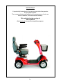
EMERALD 4-WHEEL
Scooters
Workshop Manual
EN
G
LI
SH
EMERALD
WORKSHOP MANUAL
The Emerald mobility scooter is a versatile outdoor/indoor, 4-wheeled
machine.
Features include;
Adjustable Tiller assembly, Padded seat with width adjustable armrests,
Seat slide, Seat swivel, Headrest, 3-Amp off-board automatic charger,
Integrated lights & indicators,
Hazard warning lights, Front shopping basket
and Carpeted floor matt.
Sunrise Medical is ISO 9001 certified.
This product is manufactured to comply with the requirements of
EEC directives 89/336/EEC
CE
CONTENTS
Product Information
Safety Information
Recommended Tools
Service/Inspection
Technical Specifications
Front Wheels
Rear Wheels
Tyres & Tubes
Seating
Seat Stem
Batteries & Charger
Separating the Scooter
Rear Drive Assy. Ties & Plugs
Rear Lights
Main Control Box
Drive Train Assy.
Motor & Brake Assy.
Rear Chassis Assy.
Tiller Assy.
Front Body Panel Assy.
Front Body Panel- Lights
Front Body Panel- Bumper
Main Frame Assy.
Steering Rods
Steering Head
Stub Axles
Front Suspension
Assembly Reference Photographs
1-1a
2- 3
4
5
6
7- 9
10
11-12
13-16
17
18
19
20
21- 22
23
24- 26
27- 28
29- 30
31- 35
36- 37
38- 39
40
41
42- 44
45
46
47
48- 51
1
IMPORTANT
It is potentially hazardous to fit or use any parts other than genuine
Sunrise Medical parts.
The company disclaims all liability for the consequences of such use,
which in addition, voids the machine warranty.
This vehicle is for the carriage of
ONE PERSON
And must not be used for any other purpose.
1a
EMERALD
Safety
Whilst working on powered mobility products, it is essential to observe good working
practice.
Below are a series of safety guidelines and recommendations.
Please note that these precautions are intended to serve only as a guide and are not
intended to supersede or replace any safety statute, NHS or other safety regulations.
General
•
•
•
•
Always wear suitable protective clothing when handling batteries.
Always wear suitable eye protection when drilling or inspecting.
When safe to do so, wear protective gloves when handling the running gear or batteries, as these parts are exposed to paths, parks etc.
If the drive wheels have to be raised of the floor, always use a pair of axle stands to
secure the vehicle correctly.
Batteries
All work carried out on batteries or battery boxes should demand a degree of extra caution.
•
•
•
•
•
•
•
•
•
•
•
Always make sure that the batteries are disconnected from the vehicle before commencing work.
Always check that the battery charger is disconnected from the vehicle / batteries before commencing work.
Do not smoke.
Keep batteries away from all sources of ignition.
Do not place objects on the battery tops.
Always try to keep someone within earshot of your work area so that they may come to
your assistance if needed.
Always wear personnel protection when handling batteries including, eye / face protection and gloves.
Make sure there is easy access to soap and water in case of acid spills.
Avoid touching eyes or unprotected parts of the body while working on batteries.
Remember that none sealed batteries can contaminate any packaging, housing, or
boxes they may have been transported in, so handle all packaging with care especially
when disposing of.
If battery acid should come into contact with bare skin or clothing, be sure to wash
immediately using plenty of soap and water. If battery acid enters the eyes, flush with
running cold water for as long as possible while medical help is sought.
2
EMERALD
Safety
Batteries
•
•
•
•
•
When the tops of batteries are exposed, take extra care when working on or around the
terminals.
Do not allow metal tools to drop on to or touch the exposed terminals of the batteries or
other exposed connections as this could cause a short circuit, which may result in an
explosion.
Remove personnel items of jewellery such as rings, watches, chains etc. before commencing work on batteries. If such items were to cause short circuit whist being worn,
very serious burns would result.
Batteries are constructed using very heavy materials, because of this it is essential that
correct lifting techniques be employed when moving batteries around. It is also recommended that safety footwear be worn.
When disposing of old batteries, please ensure that correct disposal procedures are
followed. Contact your local authority for their recommendations.
Battery Chargers
•
•
•
•
•
Remember battery chargers are Mains Driven Units.
Always observe all guidelines and laws relating to mains-connected installations and
equipment.
Never operate the battery charger in wet or damp conditions.
If you suspect that the charger has been exposed to water or excessive damp, do not
use it. Return the unit back to the dealer/supplier for inspection.
If the battery charger is suspected of being defective or is visibly damaged, return the
unit back to the dealer for inspection.
3
RECOMMENDED TOOLS
1.
2.
3.
4.
5.
6.
7.
8.
9.
10.
11.
12.
13.
14.
15.
16.
17.
18.
19.
20.
21.
22.
23.
24.
25.
26.
27.
28.
29.
30.
31.
32.
33.
34.
35.
Metric socket set.
Imperial socket set.
Hexagon wrenches, (imperial & metric).
3.5 - 8mm flat screwdriver.
No. 0 cross-head screwdriver.
No. 1 cross-head screwdriver.
No. 2 cross-head screwdriver.
Metric combination spanner set 5 - 25mm
Imperial combination spanner set 1/8 - 1”
Mole grips.
Long nose pliers.
Adjustable Spanner.
Combination pliers.
Ciclip pliers.
Hammer, (small & large).
Soft hammer,(rubber, hide or nylon).
Feeler gauges, (metric & imperial).
Stanley knife.
Pin punches.
Electric drill, (mains/battery).
Drill bits, (metric & imperial).
Hacksaw, (standard & junior).
Toque wrench.
Steel engineering rule.
Tape measure.
Tyre pump.
Tyre pressure gauge.
Personal safety gear.
Wire strippers/cutters.
Tag crimper.
Multi-meter.
Battery tester.
Hand held electronic programmers.
Parts manuals & wokshop manuals.
Tyre levers.
4
Service & Inspection
ANNUAL
Controller
• On/off Switch
•
• PCB Plug Connections
•
• Operation
•
• Dynamic Braking
• Programmable Settings, (where applicable).
• Test Run
Batteries
• Physical Inspection
• Connections
• Discharge Test
• Up/Down Slope
.
Wheels & Tyres
•
•
•
•
•
•
Wear
Pressure, (Pneumatic Only).
Bearings, (Where appropriate).
Wheel Nuts
Castors, (Where appropriate).
Stub Axles
Motors
•
•
•
•
•
Wiring
Noise
Connections
Brake
Brushes.
Chassis
•
•
Condition, (Welded Joints etc.).
Steering, (Twists etc.).
Upholstery / Seat
•
•
•
•
•
Seat
Back
Arm pads
Seat Slide Mechanism, (where fitted).
Set Post Assy.
5
Electrical
Loom
Connections
Lights/Indicators
•
•
•
•
•
Drive
Forwards
Reverse
Emergency Stop
Left Turn
Right Turn
•
•
Over Obstacles
Parking Brake
TECHNICAL SPECIFICATIONS
Overall Length 48" / 122 cm
Overall Width 22" / 55 cm
Maximum user weight 300 lbs / 137 kg / 21 st
Maximum Gradient 14 degrees - 115 kg user weight
11 degrees - 137 kg user weight
Range 22 m / 36 km
Speed 6 mph / 9.5 kph
Turning Radius 55" / 140 cm
Weight (excluding batteries) 158 lbs / 72 kg
Battery Capacity 36 AH
Adjustable seat height 17" - 20" / 43 cm - 51 cm
Front wheel diameter 11" / 28 cm
Rear wheel diameter 11" / 28 cm
Range given represents test conditions. Please note that temperature,
user weight, terrain and battery capacity may affect overall performance.
6
EMERALD
WHEELS FRONT
1. Use a flat-blade screwdriver to
2. carefully prize off the chrome hubcap
3. Use a 13.00mm socket wrench to
undo the centre wheel securing bolt.
4. Note the use of thread-lock on the
bolt. Be careful not to breath in the
powder residue.
5. Note the sequence of washer, split
washer and bolt.
6. Make sure the scooter is firmly
supported by axle stands or wooden
blocks, before removing the wheel.
7
EMERALD
WHEELS FRONT.....
7. Carefully remove the wheel assem- 8. There are 4 nuts & bolts securing
bly. Note that there is no drive shaft
the wheel bearing hub.
key on the front wheels.
9. Use a 13.00mm socket to loosen
the nuts, but do not try to undo them
fully yet.
10. The bolt heads are enclose in the
hub, but will drift upwards as the nuts
are loosened.
11. Use your thumb to apply gentle
pressure, preventing the heads turning.
12. The nuts can now be removed.
8
EMERALD
WHEELS FRONT.....
13. Remove the bolts & carefully lift
out the wheel hub.
14. The wheel, bearing hub and bolts.
3
5
1
2
4
15. View of the enclosed ball-race
bearings.
16. Location of the five wheel rim studs.
The numbers indicate the re-tightening
sequence
17. Before undoing the five wheel rim
studs, be sure to deflate the tyre
through the air valve.
18. Use a 5.00mm hexagon wrench to
undo each of the studs. When retightening, use the sequence shown
above.
9
EMERALD
WHEELS REAR
1. Use a flat-blade screwdriver to
2. carefully prize off the chrome hub cap.
3. Note that the centre nut has an
extra spacer fitted.
4. On the rear wheel hub there is a
key-way cut which corresponds to the
key-way on the drive shaft.
5. Carefully remove the drive key.
6. Make a note of the number of
shims used behind the rear wheels on
each axle.
10
EMERALD
WHEEL, TYRE & INNER TUBE
1. Remove the valve dust cap.
2. Use a small screwdriver or similar,
to depress the valve pin and let out as
much air as possible.
3. Use a 5.0mm Hex Key, to undo the
five rim studs.
4. Press down on the tyre with the ball
of the hands and use a tyre lever to
gently lift the rim away from the tyre.
5. Lift the rim away from the tyre.
6. View of the wheel with the first rim
removed.
11
EMERALD
WHEEL, TYRE & INNER TUBE
7. It is now possible to carefully remove and replace the inner tube.
8. If the inner rim is to be removed,
use a suitable tyre lever as before.
9. Lift the rim away from the tyre.
10. When refitting, be sure not to pinch
the inner tube between the rims.
11. To help avoid pinching, with the
rim studs half tightened, partially
inflate the inner-tube.
12. The inner tube should then seat
itself behind both rims. Re-tighten the
studs in the sequence shown previously and then inflate the tyre as
normal.
12
EMERALD
SEATING
1. Lift the armrests up for easy access.
2. Pull the seat recline lever upwards.
3. Allow the backrest to fold flat.
4. Stand behind the seat & lift the seat
swivel lever up.
5. With the seat swivel lever in the up
position, carefully lift the seat assembly off the seat stem.
6. Loosen the two armrest adjustment
knobs.
13
EMERALD
SEATING.....
7. To retract the armrest, simply pull it
out.
8. Turn the seat assy. up side down to
expose the 4-bolts securing the swivel
pate.
9. Use a 13.00mm socket wrench to
undo the nuts.
10. Remove the nuts & washers.
11. Lift the swivel plate assy. away
from the seat.
12. This exposes the armrest adjuster
bracket.
14
EMERALD
SEATING .....
13. Lift off the armrest adjuster
bracket.
14. With the seat slides set fully forward, the two rear studs can be
accessed.
15. Use a sturdy 5.00mm hex wrench
to undo all four studs. Note that these
are firmly held & some force is required.
16. The blue thread-lock is the reason
the studs are so tight.
17. Press the seat slide lever down to
move the slide to the rear. The other
slide can be pushed back freely.
18. Once the slides are pushed back,
the other two studs are exposed.
15
EMERALD
SEATING .....
19. Use a sturdy 5.00mm hex wrench
to undo these.
20. They are also held by thread-lock.
21. Once the studs have been removed lift off the seat slide.
22. And the same with the other side.
23. Finally remove the four spacer
washers.
16
EMERALD
SEAT STEM
1. To remove the Seat Stem..
2. lift the Rear Cover off its velcro
mount and clear of the scooter.
3. Loosen off the Seat Post securing
stud. There is no need to remove it.
4. Un-hook the Securing Pin spring.
5. Before pulling the Securing Pin out, 6. Lift the Seat Stem out of the Seat Post.
make sure the Seat Stem is held firm,
because it will drop sharply into the
Seat Post once the pin is out.
17
EMERALD
BATTERIES & CHARGER
1. To remove the batteries, lift the seat
off.
2. Remove the rear cover.
3. Undo the two velcro straps that
secure the batteries.
4. Disconnect the Red & the Black
battery plugs.
5. Carefully lift the batteries out.
6. Batteries, Battery Leads & Battery
Charger.
18
EMERALD
SEPARATING THE SCOOTER
1. Unplug the Main Loom at the Motor 2. Grab the Securing Pin by the loop at
the top.
end of the scooter.
3. Pull the Securing Pin out.
4. Pull the front & rear sections of the
scooter in opposite directions.
5. The two sperate sections of the
scooter.
19
EMERALD
REAR DRIVE ASSY. TIES & PLUGS
1. Undo the two screws securing the
plastic cover to the rear frame & lift
the cover off.
2. Release the loom tie holding the
main loom.
3. Cut the tie wrap holding the Red &
the Black wires to the rear frame.
4. Release the tie holding the Controller Loom.
5. Disconnect the two spade connectors on the Power Breaker.
6. Disconnect the white Motor Plug.
Remember to press the hook-lock
down to release the plug halves.
20
EMERALD
REAR LIGHTS
1. There are two Red Tail Lights & two 2. The lights are accesses from the back.
Yellow Rear Indicators
3. There are two White plugs mating
to one Green socket and one White
socket. On the other side there is the
same, but it is a Yellow socket.
4. Mark the White plug which goes to
the Green socket, (Yellow on the other
side), to aid reassembling. Do this
before disconnecting them.
5. Release the tie
wrap.
6. Carefully squeeze the two securing
lugs together using a pair of long
nosed pliers.
21
EMERALD
REAR LIGHTS.....
7. Pull the light assembly through the
bracket.
8. Withdraw the light assembly.
9. Mark the position of the indicator or 10. Note that the rear tail & indicator
lights are sealed. If a bulb blows, the
tail lamp if required.
complete assembly has to be
changed.
22
EMERALD
MAIN CONTROL BOX
1. Release all the tie wraps holding
the looms emanating from the Main
Control Box.
2. Gently pull all of the Main Control
Box looms through to the rear of the
scooter.
3. With the looms clear, carefully lift
the Main Control Box upwards, until it
slides off it’s guide.
4. A view of the Main Control Box
Mounting Bracket
5. A view of the “V” shaped Control
Box Receiver Bracket.
6. The Main Control Box & Loom.
Note that there are no serviceable parts in the Main Controller. If a fault
is suspected, please return it to Sunrise Medical for repair / replacement.
23
EMERALD
DRIVE TRAIN ASSY.
1. There are four bolts securing the
Drive Train Assembly.
2. Use a 13.00mm socket to hold the
securing nuts.
3. On the long drive shaft side, use a
screwdriver to undo the bolts.
4. Remove the two self-locking nuts.
5. Remove the two bolts.
6. Carefully remove the rubber gasket.
24
EMERALD
DRIVE TRAIN ASSY.....
7. Remove the brass bracket complete with the rubber gaiter.
8. Use a 13.00mm socket to undo the
nuts on the “U” bolt side of the drive
train.
9. Remove the brass bracket.
10. Remove the rubber gaiter.
11. Carefully lift out the “U” bracket by
moving the Drive Train until the bolts
are clear of the frame.
12. Be careful not to lose the arched
sleeve that is positioned at the inside
top of the “U” bolt.
25
EMERALD
DRIVE TRAIN ASSY.....
13. Retract the Drive Train Assy. Use
caution as this part is heavy
14. The left hand Drive Train fixings.
15. The right hand Drive Train fixings.
16. The complete Drive Train Assy & fixings.
26
EMERALD
MOTOR/ELECTRONIC BRAKE ASSY.
1. A 6.00mm hex wrench is the basic
tool required for undoing the four
Motor Studs.
2. Some of the studs may require
extra force. That may require a
cranked hex key or tool.
3. Limited room may also require the
use of a hex key driver tool. If the
Drive Train has to be removed, do
that first and then take the Motor off.
4. It is a good idea to mark the top of
the Motor and Transaxle for refitting
purposes.
5. Carefully withdraw the Motor from
the Transaxle.
6. The Motor/Electronic Brake Assy.
27
EMERALD
MOTOR/ELECTRONIC BRAKE ASSY.....
7. When refitting the Motor, be sure to
line-up the Motor drive coupling with
the drive coupling in the Transaxle.
8. One of the two Motor Brush Housings.
9. To inspect the Brushes, undo the
housing cap using a flat-blade screwdriver.
10. Be carefull not to lose the cap.
11. Inspect the Carbon for cracks or excessive wear-down. Check the Copper
terminal and wire for broken connections or green discolouration. If any of the
above are found, replace the Motor Brushes as a set.
28
EMERALD
REAR CHASSIS ASSY.
1. Disconnect the Power-breaker....
2. and use a 14.00mm spanner to undo it.
3. Check that there are no broken
terminals or cracks in the Powerbreaker body
4. The Power-breaker & fixings.
5. The Rear Suspension Struts.
6. The top of one of the struts. Note
that there are no nuts, just a bolt into a
threaded housing.
29
EMERALD
REAR CHASSIS ASSY.....
7. Use a 13.00mm socket to undo the
top bolt.
8. Withdraw the bolt, but be aware
that if the strut on the other side has
been removed, the frame top section
will drop on its hinges
9. Use the 13.00mm socket to undo
the bottom bolt.
10. Withdraw the bolt.
11. One of the two Rear Suspension
Struts.
12. The Rear Frame Assy.
30
EMERALD
TILLER ASSY.
1. Undo the single screw on the inside
cover of the Tiller and lift the cover
away.
2. The Orange Main Loom Plug is
exposed.
3. Depress the plastic lock latch and
separate the plug and socket.
4. Undo the two screws that secure the
Basket Bracket to the front of the Tiller.
5. Remove the Basket Bracket.
6. Undo screws at the top of the Tiller next
to the handle bar on the left....
31
EMERALD
TILLER ASSY.....
7. ....and the right-hand screw.
8. Unclip the 3-way molex plug located
behind the Tiller Panel.
9. Unclip the 2-way molex plug.
10. Finally, un-clip the Blue molex plug.
11. Undo the small brass screws that
secure the Throttle PCB to the handle
bar assy.
12. Lift the Tiller Panel away from the
handle bar assy.
32
EMERALD
TILLER ASSY.....
13. Undo the two small brass screws
securing the WigWag assy.
14. Remove the WigWag assy from
the handle bar.
15. Turn the Preset Speed pot to
either min. or max, then remove the
pointer knob by pulling it upwards.
When refitting, align the pointer to the
chosen min. or max position.
16. Use an 11.00mm spanner to
partially loosen the securing nut. Be
careful not to tear the min.-max decal
below. When refitting, do not overtighten.
17. To avoid damage to the min.18. Withdraw the Pot. Note that there
max.. decal, use the fingers to remove is a low tack glue used on the Pot
the loosened nut.
face. It is advisable to use a low tack
compound or a star washer when
refitting. This prevents the Pot body
turning against the securing nut.
33
EMERALD
TILLER ASSY.....
19. Press out the two plastic pop
rivets to remove the Bar Graph PCB.
20. The two wires on the back of the
Key Switch, have to be de-soldered
for removal and soldered back on.
21. Use a 22.00mm spanner to
loosen the Key Switch retaining nut.
22. Once loosened, it is easier to use
the fingers to undo the nut and remove
the plastic spacer.
23. Withdraw the Key Switch.
24. Use a small X-head screwdriver for
the outer screws on the Charger Socket.
34
EMERALD
TILLER ASSY.....
25. Use a pair of long or snipe-nosed
pliers to hold the small self-locking
nuts at the back of the Charger
Socket.
26. Withdraw the Charger Socket
assy from the Tiller Panel.
27. The two Tiller securing bolts are
located just above the Tiller Adjustment Mechanism.
28. Use a 10.00mm socket & spanner
to undo the two bolts.
29. The two bolts can be withdrawn
easier if the Tiller Shaft is gently
rocked back and forth whilst pulling
the bolts out.
30. Lift the Tiller Shaft off the Tiller
Adjustment Mechanism.
35
EMERALD
FRONT BODY PANEL
1. Peel up one corner of the carpet to
get a good grip.
2. Lift the carpet mat off its velcro
pads.
3. This exposes the six body panel
screws.
4. Undo the six screws.
5. Lift off the plastic groove cover.
6. Lift up the rubber Tiller Gaiter to
expose the two lower fixing bolts.
36
EMERALD
FRONT BODY PANEL
1. Use a 10.00mm socket & spanner
to undo the two bolts.
2. Withdraw the two
bolts.
3. Lift up the body panel to expose the 4. Mark the loom plug and socket
front light connections. Temporarily rest sides, to aid refitting.
the panel on the Tiller Adjuster to gain
access to the plugs.
5. Mark the other side also and
disconnect the two plugs.
6. Lift the Front Panel clear of the
chassis.
37
EMERALD
FRONT BODY PANEL & LIGHTS
1. Lift the Tiller Adjustment Mechanism 2. Pull the Rubber Gaiter off the Main
off the Steering Head.
Loom.
3. The Front Light Cluster is held in
place by mounting springs and
screws.
4. Note the position of the springs before
undoing the self tapping screw.
5. Remove the screw and the spring.
6. Do the same for the other screw.
38
EMERALD
FRONT BODY PANEL & LIGHTS
7. Withdraw the Front Light Cluster
from the front of the panel.
8. The Front Light Cluster & Springs.
9. The Headlamp and Indicator sockets are accessible from the back of
the cluster.
10. Pull the plastic bulb mounts out of
the cluster body, to access the bulbs.
11. To release the bulb, gently pull on
the glass envelope. Take care as the
bulb is cap-less and the glass and can
break.
12. Make sure that the copper terminals do not touch as this will cause a
short circuit. After changing bulbs,
always try the lights prior to returning
to the customer.
39
EMERALD
FRONT BODY PANEL & BUMPER
1. Front Bumper Fixing.
2. Use a 10.00mm socket to undo the
nut. When refitting, do not overtighten.
3. The nut, spring washer and large
washer.
4. The Front Bumper Assy.
5. Overview of the Tiller Parts.
6. Overview of the Front Body Panel parts.
40
EMERALD
MAIN FRAME ASSY.
1. Cut any remaining tie wraps still
securing the Main Loom to the
chassis.
2. Feed the plug through the hole in
the front chassis member.
3. Retract the plug through the hole at
the back of the front chassis member
and remove the Main Loom.
4. The two front Suspension Struts
and the two nuts securing the Steering
Cover.
5. Use a 10.00mm socket to undo the
two nuts.
6. Lift the Steering Cover away from
the chassis.
41
EMERALD
STEERING RODS
1. Connection of the Steering Rods to 2. Use a 13.00mm socket to undo the selfthe Steering Head. Note that there is locking nut.
adjustment at the ends of each Steering Rod
3. Drop the rod away from the Steering Head and lift the spacer off.
5. The connection with the left-hand
Stub Axle.
4. Remember to make a note of the
spacer positions to aid refitting.
6. Use a 13.00mm spanner/socket to
undo the bolt and self-locking nut.
42
EMERALD
STEERING RODS.....
7. Drop the rod out of the Stub Axle.
8. Lift the small spacer off.
9. Withdraw the bolt.
10. Use a 13.00mm spanner/socket to
undo the bolt and self-locking nut on
the other Stub Axle.
11. Drop the rods away from the Stub
Axle.
12. Lift the small spacer off the bolt.
43
EMERALD
STEERING RODS.....
13. Separate the two rods.
14. Lift the small spacer off the bolt.
15. Withdraw the bolt.
16. The Steering Rod Set showing the positions of the nuts, spacers and bolts.
44
EMERALD
STEERING HEAD
1. Use a 30.00mm spanner to loosen
the Steering Head Retaining Nut.
2. Once loosened, use the fingers to
undo completely.
3. Note that there is a shoulder at the
top of the nut.
4. The larger Bearing Retaining Nut should
undo using hand pressure, but mole grips
can be used if this is tight.
5. Use a pair of thin-nosed pliers to
remove the top bearings.
6. As the Steering Head is lowered,
the bottom bearings can be seen.
Note also the position of the Steering
Stop Bolt
45
EMERALD
STUB AXLES
1. Use a 15.00mm spanner and a
2. Remove the nut.
sturdy 15.00mm socket, to undo the
Stub Axle nut and square-headed bolt.
3. Remove the square-headed bolt.
4. Lift the Stub Axle away from its
mount. Note that there is an adjustable
steering stop bolt attached to the Stub
Axle.
5. Remove the two spacers.
Repeat the process for the other Stub
Axle.
46
EMERALD
FRONT SUSPENSION
1. Use a 13.00mm socket to undo the
top bolt. Note that there is no nut with
this bolt as the bolt locates into a
threaded hole.
2. Remove the Hexagon Flangehead bolt.
3. Use two 13.00mm spanners to
undo the bottom fixing.
4. This is a conventional nut......
5. .....and bolt.
6. Remove the Suspension Strut.
Do the same for the other side.
47
EMERALD
ASSEMBLY REFERENCE PHOTO’s
MAIN FRAME ASSEMBLY
48
EMERALD
ASSEMBLY REFERENCE PHOTO’s
MAIN BODY ASSEMBLY
49
EMERALD
ASSEMBLY REFERENCE PHOTO’s
TILLER ASSEMBLY
50
EMERALD
ASSEMBLY REFERENCE PHOTO’s
REAR DRIVE ASSEMBLY
51
Please use this Wokshop Manual
in conjunction with the Emmerald
Owners Manual & Parts Manual.