1
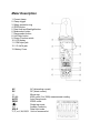
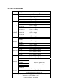
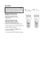
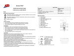
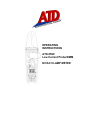
OPERATING
INSTRUCTIONS
ATD-5590
Low Current Probe/DMM
DC/AC CLAMP METER
Safety
International Safety Symbols
This symbol, adjacent to another symbol or
terminal, indicates the user must refer to the
manual for further information
This symbol, adjacent to a terminal, indicates that,
under normal use, hazardous voltages may be
present
Double insulation
SAFETY NOTES
• Do not exceed the maximum allowable input range of any function
• Do not apply voltage to meter when resistance function is selected.
• Set the function switch OFF when the meter is not in use.
WARNINGS
• Set function switch to the appropriate position before measuring.
• When measuring volts do not switch to current/resistance modes.
• Do not measure current on a circuit whose voltage exceeds 240V.
• When changing ranges using the selector switch always disconnect the
test leads from the circuit under test.
• Do not exceed the maximum rated input limits.
CAUTIONS
Improper use of this meter can cause damage, shock, injury or death.
Read and understand this user manual before operating the meter.
Always remove the test leads before replacing the battery.
Inspect the condition of the test leads and the meter itself for
any damage before operating the meter. Repair or replace
any damage before use.
Use great care when making measurements if the voltages
are greater than 25VAC rms or 35VDC. These voltages are
considered a shock hazard.
Remove the battery if the meter is to be stored for long
periods.
Always discharge capacitors and remove power from the
device under test before performing Diode, Resistance or
Continuity tests.
• Voltage checks on electrical outlets can be difficult and
misleading because of the uncertainty of connection to the
recessed electrical contacts. Other means should be used
to ensure that the terminals are not "live".
• If the equipment is used in a manner not specified by the
manufacturer, the protection provided by the equipment may
be impaired.
Function A AC, A DC V DC, V AC Input Limits Maximum Input 80A 600V DC/AC Resistance, Diode, Continuity, Frequency, Duty Cycle, Capacitance Test. 250V DC/AC Meter Description
1. Current clamp
2. Clamp trigger
3. Safety protection ring
4. ZERO button
5. Data Hold and Backlight button
6. Mode select button
7. Range select button
8. Hz/%duty button
9. Rotary Function switch
10. LCD display
11. COM input jack
12. V Ω Hz/% jack
13. Battery Cover
AC
DC
(-)
8.8.8.8
AUTO
ZERO
AC (alternating current)
DC (direct current)
Minus sign
4000 count (0 to 3999) measurement reading
Auto Range mode
ZERO mode
•)))
HOLD
℃,℉, m,V,A,K,M,Ω
Diode test mode
Audible Continuity
Data Hold mode
Units of measure list
SPECIFICATIONS
Range & Resolution Accuracy (% of reading) 4.000 A DC ± (2.8% + 10 digits) 80.0 A DC ± (3% + 8 digits) 4.000 A AC ± (3.0% +10digits) 80.0A AC ± (3.0% + 8 digits) 400.0 mV DC ± (1.0% + 15 digits) 4.000 V DC ± (1.0% + 3 digits) DC Voltage 40.00 V DC ± (1.5% + 3 digits) 400.0 V DC 600 V DC ± (2.0% + 3 digits) 400.0 mV AC ± (1.0% + 30 digits) AC Voltage 4.000 V AC (50/60Hz) 40.00 V AC ± (2.0% + 5 digits) 400.0 V AC 600 V AC ± (2.0% + 5 digits) 400.0 Ω ± (1.0% + 4 digits) 4.000KΩ 40.00KΩ ± (1.5% + 2 digits) Resistance 400.0KΩ 4.000MΩ ± (2.5% + 3 digits) 40.00MΩ ± (3.5% + 5 digits) 40.00nF ±(5.0% reading + 30digits) 400.0nF ±(3.0% reading + 5 digits) Capacitance 4.000μF ±(3.5% reading + 5 digits) 40.00μF 100.0μF ±(5.0% reading + 5 digits) 5.000Hz ±(1.5% reading + 5 digits) 50.00Hz ±(1.2% reading + 2 digits) 500.0Hz 5.000kHz Frequency 50.00kHz Sensitivity: 10Vrms min. @ 20% to 80% duty cycle 500.0kHz 5.000MHz 10.00MHz 0.5 to 99.0% ±(1.2% reading + 2 digits) Duty Cycle Pulse width: 100μs ‐ 100ms, Frequency: 5Hz to 150kHz; Sensitivity: 10Vrms min. Analog output: (for ACA & DCA range), 10mV/Amp (20KHz at ±3dB) Accuracy: ± ( 4.5% reading + 1mV ) Output impedance: approx 3KΩ Function DC Current AC Current (50/60Hz) Clamp size
Opening 0.5" (23mm) approx
Diode Test
Test current of 0.3mA typical;
Open circuit voltage 1.5V DC
typical.
Continuity Check
Threshold <150Ω; Test
current< 1mA
Low Battery Indication
“
”
is displayed
Overrange Indication
“OL” is displayed
Measurements Rate
2 per second, nominal
Input Impedance
7.8MΩ (VDC and VAC)
Display
4000 counts LCD
Operating Temperature 14° to 122°F (-10° to 50° C)
Storage Temperature
-22° to 140°F (-30° to 60°C)
Relative Humidity
90%(0°C to 30°C); 75%(30°C to 40°C);
45%(40°C to 50°C)
Altitude Operating:
3000m; Storage 10,000m
Over voltage
Category III 600V
Battery
Two 1.5V “AAA” Batteries
Auto OFF
approx. 25 minutes
Dimensions/Weight
200x50x35mm/200g
Safety
For indoor use and in accordance with Overvoltage
Category II, Pollution Degree 2. Category II includes local
level, appliance, portable equipment, etc., with transient
overvoltages less than Overvoltage Cat. III
Operation
NOTICES: Read and understand all warning
and precaution statements listed in the safety
section of this operation manual prior to using
this meter. Set the function select switch to the
OFF position when the meter is not in use.
AC/DC Current Measurements
WARNING: Ensure that the test
leads are disconnected from the
meter before making current clamp
measurements.
1. Set the Function switch to the
80ADC, 4ADC, 80AAC or 4AAC
range. If the range of the measured
is not known, select the higher range
first then move to the lower range if necessary.
2. Press the trigger to open jaw. Fully enclose one
conductor wire to be measured.
3. If measuring DCA, press ZERO button to
enter the zero reading.
4. The clamp meter LCD will display the reading.
DC/AC Voltage Measurements
1. Insert the black test lead into the negative COM terminal
and the red test lead into the positive V terminal.
2. Set the function switch to the V position.
3. Select AC or DC with the MODE button.
4. Connect the test leads in parallel with the circuit under test.
5. Read the voltage measurement on the LCD display.
Resistance and Continuity Measurements
1. Insert the black test lead into the negative COM terminal
and the red test lead into the positive terminal.
2. Set the function switch to the
•))) Ω position.
3. Use the multifunction MODE button to select resistance.
4. Touch the test probe tips across the circuit or component
under test. It is best to disconnect one side of the device under test
so the rest of the circuit will not interfere with the resistance reading.
5. For Resistance tests, read the resistance on the LCD display.
6. For Continuity tests, if the resistance is < 150Ω, a tone will sound.
Diode Measurements
1. Insert the black test lead banana plug into the negative
COM jack and the red test lead banana plug into the
positive diode jack.
2. Turn the rotary switch to the
•))) position.
3. Press the MODE button until “ “ appears in the display.
4. Touch the test probes to the diode under test.
Forward voltage will indicate 0.4V to 0.7V.
Reverse voltage will indicate “OL”.
Shorted devices will indicate near 0mV and an open device
will indicate “OL” in both polarities.
Capacitance Measurements
WARNING: To avoid electric shock, disconnect power to
the unit under test and discharge all capacitors before
taking any capacitance measurements. Remove the
batteries and unplug the line cords.
1. Set the rotary function switch to the cap position.
2. Insert the black test lead banana plug into the negative (COM) jack.
Insert the red test lead banana plug into the positive (V) jack.
3. Touch the test leads to the capacitor to be tested.
4. Read the capacitance value in the display
Frequency or % duty cycle measurements
1. Set the rotary function switch to the “Hz/%” position.
2. Insert the black lead banana plug into the negative COM jack
and the red test lead banana plug into the positive V jack.
3. Select Hz or % duty with the Hz/% button.
4. Touch the test probe tips to the circuit under test.
5. Read the frequency on the display.
Data Hold
To freeze the LCD meter reading, press the data hold button.
The data hold button is located on the left side of the meter (top button).
While data hold is active, the HOLD display icon appears on the LCD.
Press the data hold button again to return to normal operation.
Note: The HOLD feature will activate when the Backlight is turned on.
Press the HOLD key again to exit Hold.
Backlight
Press and hold the HOLD key for >1 second to turn on or off the display backlight function.
Note: The HOLD feature will activate when the Backlight is
turned on. Press the HOLD key again to exit Hold.
ZERO BUTTON
For DCA and Capacitance Zero & Offset adjustment.
Manual Ranging
The meter turns on in the autoranging mode. Press the Range button to go to manual
ranging. Each press of the range button will step to the next range as indicated by the
units and decimal point location. Press and hold the Range button for two seconds to return
to autoranging. Manual ranging does not function in the AC Current , Diode and
Continuity check functions
Battery Replacement
1. Remove the one rear Phillips head screw
2. Open the battery compartment
3. Replace the Requires two “AAA” batteries (UM4 R03)
4. Re-assemble the meter
Warranty Information
This product is warranted to be free from defects for one year. If this product fails during the
first 12 months due to faulty materials or workmanship, it will be replaced free of charge, at
the discretion of the manufacturer.
NOTE: This one year warranty does not cover dead batteries and blown fuses.
For warranty and service coverage, please return this product to your dealer for processing
and evaluation. OR, return it directly to:
Electronic Specialties, Inc.
139 Elizabeth Ln.
Genoa City, WI 53128
262-279-1400
WWW.ESITEST.COM
Defective units being returned to your dealer or to the factory should include proof of
purchase date. Any testers that do not function due to misuse or abuse will be subject to
“out of warranty service charges.”