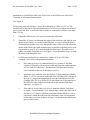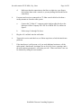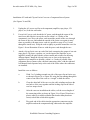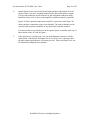
1
JAMES B. HATFIELD, PE
BENJAMIN F. DAWSON III, PE
THOMAS M. ECKELS, PE
STEPHEN S. LOCKWOOD, PE
DAVID J. PINION, PE
HATFIELD & DAWSON
CONSULTING ELECTRICAL ENGINEERS
9500 GREENWOOD AVE. N.
SEATTLE, WASHINGTON 98103
TELEPHONE
(206) 783-9151
FACSIMILE
(206) 789-9834
E-MAIL
[email protected]
MAURY L. HATFIELD, PE
CONSULTANT
BOX 1326
ALICE SPRINGS, NT 5950
AUSTRALIA
PAUL W. LEONARD, PE
ERIK C. SWANSON, EIT
THOMAS S. GORTON, PE
HANDBOOK
ELIMINATING RADIO FREQUENCY
BLANKETING INTERFERENCE
FROM ELECTRONIC EQUIPMENT
A BRIEF TUTORIAL
UPDATED JANUARY 2003
the radio station XX.X MHz, City, State
Page 1 of 20
Introduction
This manual contains a description of the techniques and materials for eliminating the
effects of "blanketing" interference from FM radio stations Many residents living in the
vicinity of the transmitters have experienced problems with interference to their
telephones, FM radios, television sets, "boomboxes", and stereo equipment caused by the
strong signal produced by the FM radio station in the immediate vicinity of its transmitter
site.
"Blanketing interference" to TV and radio receivers occurs when an FM broadcast
station's signal strength at the affected receiver is sufficiently strong to "overload" the
receiver, and to partially or completely block it from receiving other broadcast signals.
Blanketing interference is a function of receiver design characteristics; some receivers are
affected more than others in the presence of a strong signal from an FM broadcast station.
Also, the effects of blanketing interference are more severe when the TV or FM receiver
is tuned to a weaker desired signal rather than to a stronger one. FM broadcast stations
must radiate relatively high levels of power from their transmitting antennas in order to
provide coverage to their areas of service. Therefore, the available solutions for
blanketing interference problems all involve either increasing the level of the desired
signal (the signal from the TV station you are trying to watch or the FM broadcast station
you are trying to listen to) and/or decreasing the level of the interfering signal (the signal
from the radio station) at the antenna input to the TV or FM receiver. In the case of other
electronic equipment such as telephones and cassette players, for example, preventing
interference involves preventing the radio frequency energy from the radio station from
entering the circuitry of the equipment.
The techniques for eliminating blanketing interference described in this tutorial have
been used successfully by various radio station personnel to solve a significant number of
interference problems in households throughout the immediate vicinity of its transmitter
site; some have been as close as 75 feet to the transmitting facility. The filters shown in
the diagrams in the following pages are used to "notch" out the radio station signal at the
input to a TV or FM receiver without causing a significant reduction of the other
available TV or FM signals at the receiver. The "toroid" (do-nut shape) and "clip-on"
ferrite cores are made of a special material which blocks the energy at radio station
frequency from entering the device on which they are used. A combination of filters and
ferrite devices is usually needed to eliminate blanketing interference in given TV, FM
receiver, or other device.
Blanketing interference to TV signals from FM radio stations usually appears as a
"herringbone" pattern of zig-zag vertical lines in the TV picture or as the radio station’s
audio (describe format, if possible) over the TV sound. The interference usually affects
channels 5 and 7 more severely than the other channels for televisions receiving signals
directly off-the-air, although channel 9 may also be affected. The interference may be so
severe that it completely wipes out the picture with the "herringbone" pattern, or it may
be very subtle, showing up as a slight "fuzziness" in the picture on channel 5 or 7. It
usually does not affect channels 4, 11, 13, 20, 22, or 28. Horizontal white lines moving
through the picture or white "sparklies" running from the top to the bottom of the picture
Hatfield & Dawson Consulting Engineers
the radio station XX.X MHz, City, State
Page 2 of 20
are the result of interference from household power line noise and are not the result of
blanketing from the radio station. The power line interference is quite common in
(affected community), where most of the off-the-air signals are relatively weak. It is
especially noticeable on channel 4. A single vertical bar running from the top to the
bottom of the picture is the result of a reflected signal or co-channel interference, and is
also not related to the radio station. "Ghosts" in the TV picture are caused by reflected
TV signals or by a damaged outdoor antenna system, and are not related to blanketing
interference from the radio station. A "snowy" picture is usually the result of inadequate
TV signal strength and is not the result of blanketing interference.
In some cases, it may not be possible to eliminate the effects of blanketing interference to
a television receiver, FM radio, or a tape player in a "boombox" or a portable stereo,
especially those portable stereos with plastic cases. In these cases, it is necessary to
replace the receiver, "boombox" or tape player with a comparable piece of equipment
which is known to function satisfactorily in the vicinity of a strong signal from radio
station. A list of equipment known to operate without problems in the radio station
blanketing interference area is shown in Exhibit 7.
The information shown in Exhibit 7 was gathered nearly 10 years ago, and the
model numbers described in the Exhibit are no longer available. However, it is
likely that the models now produced by the manufacturers listed in the category
describing TV receivers that perform adequately with the addition of external filters
will also provide adequate performance with external filtering.
Because of the wide variation in the performance of TV receivers, AM/FM
“Boomboxes”, and component stereo systems observed in the original
measurements, the most prudent approach to purchasing new consumer home
entertainment equipment for use in households within the the radio station
blanketing contour is to make sure that a particular piece of equipment can be
returned and exchanged for a different model if it is determined that the equipment
is not capable of satisfactory operation, even with external filtering, in a residence
near the radio station transmitter. Most major retail consumer electronics outlets
have reasonable return policies that should allow such an exchange, especially if the
consumer discusses the potential interference problems with store personnel in
advance of the sale.
The filters and ferrite cores shown in the attached drawings are all available from the
radio station. These filters and ferrite cores can be obtained by calling ###-#### (the
Station’s "Interference Assistance" number) and leaving a voice mail message so that a
representative of the radio station can return your call and arrange to provide you with
these devices and with further assistance, if necessary.
Hatfield & Dawson Consulting Engineers
the radio station XX.X MHz, City, State
Page 3 of 20
Installation of a Notch Filter and Ferrite Toroid Core on a TV Receiver with a 75 Ohm
“F” Connector Antenna Input
(See Figure 1)
1.
Unplug the TV's AC power cord from the wall outlet.
2.
Thread the AC power cord through the center of the toroid core and slide the core
up the cord to within 1 or 2 inches of the TV set. Wrap the power cord around the
outside of the core, through the center of the core, and around the outside of the
ferrite core again as many times as possible (with most power cords it is possible
to wrap 10 or 11 turns through the toroid core). Wrap the cord at tightly as
possible around the core. See Figure 1 for an illustration of how to wind the
power cord through the core.
3.
Disconnect the 75 Ohm “F” connector on the antenna or cable system lead-in
from the antenna input at the rear of the TV. Connect the Microwave Filter
Company 5KV-XX.X or 5KFM-XX.X (where XX.X is the station’s operating
frequency in MHz) notch filter directly to the antenna input at the rear of the TV.
Connect the antenna or cable system lead-in to the opposite end of the filter from
the TV. Make sure that the connections are tight (use your fingers, don't tighten
them with a wrench, or you may damage the threads on the connectors).
If you have an external antenna with 300 Ohm “twinlead” flat cable as the
antenna lead-in, then there is already a 300 Ohm/75 Ohm transformer installed
between the 300 Ohm cable and the 75 Ohm “F” connector on the TV. Install the
filter between the transformer and the TV'S 75 Ohm input connector
4.
Plug the AC cord back into the wall outlet
5.
Turn on the TV and check to see if these steps have solved the interference
problems. Check solid, single color areas of the picture for signs of herringbone
interference (vertical zigzag lines).
6.
If the interference is still present, or if you need additional assistance, call the
radio station’s Interference Assistance line at ###-####, leave a message, and a
the radio station representative will return your call. Filters and ferrite cores can
be obtained by calling the same number.
Hatfield & Dawson Consulting Engineers
the radio station XX.X MHz, City, State
Page 4 of 20
Installation of a Notch Filter and Ferrite Toroid Core on a TV Receiver with Screw
Terminals at its Antenna Input
(See Figure 2)
1.
Unplug the TV's AC power cord from the wall outlet.
2.
Thread the AC power cord through the center of the toroid corn and slide the core
up the cord to within 1 or 2 inches of the TV set. Wrap the power cord around the
outside of the core, through the center of the core, and around the outside of the
ferrite corn again as many times as possible (with most power cords it is possible
to wrap 10 or 11 turns through the toroid core). Wrap the cord at tightly as
possible around the core. See Figure 1 for an illustration of how to wind the
power cord through the core.
3.
For TV's connected to “rabbit ears” or to a 300 Ohm “twinlead” (flat cable)
rooftop antenna downlead:
a.
If the TV is connected directly to a section of 300 Ohm “twinlead” (flat
cable with two wires at the end) from the rooftop antenna or from a pair of
“rabbit ears”, disconnect the 300 Ohm cable from the screw terminals at
the rear of the TV.
b.
Attach the screw terminals on a 300 to 75 Ohm transformer (Radio Shack
15-1252 or equivalent) to the end of the 300 Ohm cable, and attach the
type “F” plug on the transformer to one end of the Microwave Filter
Company 5KV-XX.X or 5KFM-XX.X notch filter (the “F” plug attaches
to the end of the filter with the screw threads on the outside of the filter's
connector--see Figure 2).
c.
If your TV has a single set of screw terminals at its antenna input, connect
the other end of the filter to a 75 Ohm-to-300 Ohm transformer (Radio
Shack #15-1140 or equivalent). Attach the leads from the transformer to
the screw terminals on the TV as shown in Figure 2 (it doesn't matter
which lead goes to which screw).
d.
If your TV has two separate sets of screw terminals labeled “VHF” and
“UHF”, connect the other end of the filter to a 75 Ohm-to-300 Ohm
VHF/UHF splitter combiner (Radio Shack # 5-1252 or equivalent). Attach
the leads from the splitter/combiner to the appropriate screw terminals on
the TV as shown in Figure 2 (both the splitter combiner and the TV will
be labeled “VHF” and “UHF”)
Hatfield & Dawson Consulting Engineers
the radio station XX.X MHz, City, State
e.
4.
Page 5 of 20
Make sure that the connections to the filter are tight (use your fingers,
don't tighten them with a wrench, or you may damage the threads on the
connectors)
For TV's connected to a 75 Ohm coaxial cable lead-n from a rooftop antenna or
from the cable system:
a.
Connect the 75 Ohm “F” connector on the lead-in cable directly to the
Microwave Filter Company 5KV-XX.X or 5KFM-XX.X filter, as shown
in figure 2.
b.
Follow steps 3c through 3e, above.
5.
Plug the AC cord back into the wall outlet.
6.
Turn on the TV and check to see if these steps have solved the interference
problems. Check solid, single color areas of the picture for signs of herringbone
interference (vertical zigzag lines).
7.
If the interference is still present, or if you need additional assistance, call the
radio station’s Interference Assistance line at ###-####, leave a message, and a
the radio station representative will return your call. Filters and ferrite cores can
be obtained by calling the same number.
Hatfield & Dawson Consulting Engineers
the radio station XX.X MHz, City, State
Page 6 of 20
Installation of a Notch Filter and Ferrite Toroid Core on an FM Receiver with a 75 Ohm
“F” Connector External Antenna Input
(See Figure 1)
Figure 1 shows the installation of a filter on a TV set. The installation of a filter on the
external antenna input of an FM receiver follows the identical process; only the “box” to
which the filter or leads are connected is an FM receiver rather than a TV set.
1.
Unplug the FM receiver's AC power cord from the wall outlet.
2.
Thread the AC power cord through the center of the toroid core and slide the core
up the cord to within 1 or 2 inches of the receiver. Wrap the power cord around
the outside of the core, through the center of the core, and around the outside of
the ferrite core again as many times as possible (with most power cords it is
possible to wrap 10 or 11 turns through the toroid core). Wrap the cord as tightly
as possible around the core. See Figure 1 for an illustration of how to wind the
power cord through the core.
3.
Disconnect the 75 Ohm “F” connector on the antenna or cable system lead-in
from the antenna input at the rear of the receiver. Connect the Microwave Filter
Company 5KV-XX.X or 5KFM-XX.X notch filter directly to the antenna input at
the rear of the receiver. Connect the antenna or cable system lead-in to the
opposite end of the filter from the receiver. Make sure that the connections are
tight (use your fingers, don't tighten them with a wrench, or you may damage the
threads on the connectors).
4.
Plug the AC cord back into the wall outlet.
5.
Turn on the receiver and check to see if these steps have solved the interference
problems.
6.
If the interference is still present, or if you need additional assistance, call the
radio station’s Interference Assistance line at ###-####, leave a message, and a
the radio station representative will return your call. Filters and ferrite cores can
be obtained by calling the same number.
Hatfield & Dawson Consulting Engineers
the radio station XX.X MHz, City, State
Page 7 of 20
Installation of a Notch Filter and Ferrite Toroid Core on an FM Receiver with Screw
Terminals at its External Antenna Input
(See Figure 2)
The drawing at the top of Figure 2 shows the installation of a filter on a TV set. The
installation of a filter on the external antenna input of a FM receiver follows the identical
process; only the “box” to which the filter or leads are connected is a FM receiver rather
than a TV set.
1.
Unplug the FM receiver's AC power cord from the wall outlet.
2.
Thread the AC power cord through the center of the toroid core and slide the core
up the cord to within 1 or 2 inches of the FM tuner or receiver. Wrap the power
cord around the outside of the core, through the center of the core, and around the
outside of the ferrite core again as many times as possible (with most power cards
it is possible to wrap 10 or 11 turns through the toroid core). Wrap the cord as
tightly as possible around the core. See Figure 1 for an illustration of how to wind
the power cord through the core.
3.
For FM tuners and receivers connected to “rabbit ear” or to a 300-Ohm
“twinlead” (flat cable) rooftop antenna downlead:
a.
If the tuner or receiver is connected directly to a section of 300 Ohm
“twinlead” (flat cable with two wires at the end) from the rooftop antenna
or from a pair of “rabbit ears”, disconnect the 300 Ohm cable from the
screw terminals at the rear of the tuner or receiver
b.
Attach the screw terminals on a 300 Ohm-to-75 Ohm transformer (Radio
Shack 15-1252 or equivalent) to the end of the 300 Ohm cable, and attach
the type “F” plug on the transformer to one end of the Microwave Filter
Company 5KV-XX.X or 5KFM-XX.X notch filter (the F plug attaches to
the end of the filter with the screw threads on the outside of the filter's
connector - see Figure 2).
c.
If the tuner or receiver has a set of screw terminals labeled “300 Ohms”,
or simply, “external antenna” at its antenna input, connect the other end of
the filter to a 75 Ohm-to-300 Ohm transformer (Radio Shack#15-1140 or
equivalent). Attach the leads from the transformer to the screw terminals
on the tuner or receiver as shown in Figure 2 (it doesn't matter which lead
goes to which screw).
Hatfield & Dawson Consulting Engineers
the radio station XX.X MHz, City, State
d.
4.
Page 8 of 20
Make sure that the connections to the fitter are tight (use your fingers,
don't tighten them with a wrench, or you may damage the threads on the
connectors).
For tuners and receivers connected to a 75 Ohm coaxial cable lead-in from a
rooftop antenna or from the cable system:
a.
Connect the 75 Ohm “F” connector on the lead-in cable directly to the
Microwave Filter Company 5KV-XX.X or 5KFM-XX.X, as shown in
figure 2.
b.
Follow steps 3c through 3d, above.
5.
Plug the AC cord back into the wall outlet.
6.
Turn on the receiver and check to see if these steps have solved the interference
problems.
7.
If the interference is still present, or if you need additional assistance, call the
radio station’s Interference Assistance line at ###-####, leave a message, and a
the radio station representative will return your call. Filters and ferrite cores can
be obtained by calling the same number.
.
Hatfield & Dawson Consulting Engineers
the radio station XX.X MHz, City, State
Page 9 of 20
Installation of Toroid and Clip-on Ferrite Cores on a Component Stereo System
(See Figures 3A and 3B)
1.
Unplug the AC power cord for each component (amplifier, tape player, CD
player, etc.) from the wall outlet.
2.
For each AC power cord, thread the AC power cord through the center of the
toroid core and slide the core up the cord to within 1 or 2 inches of the
component's case. Wrap .the power cord around the outside of the core, through
the center of the core, and around the outside of the ferrite core again as many
times as possible (with most power cords it is possible to wrap 10 or 11 turns
through the toroid core). Wrap the cord as tightly as possible around the core. See
Figure 1 for an illustration of how to wind the power cord through the core.
3.
Attach a clip-on ferrite core on each of the leads connecting the output of one unit
(tape player, CD player, equalizer, etc.) to the input of the amplifier or preamplifier (usually the unit with the volume control and switches for choosing
different inputs). Install the clip-on ferrite core as close to the input to the
amplifier or pre-amplifier as possible, within 1 or 2 inches if possible. Most
component stereo systems come with dual connecting cables, with the right and
left channels leads separated only at the ends of the cables where the connectors
are installed.
Install the cores as follows:
a.
Wind 2 or 3 windings around one side of the open clip-on ferrite core,
as shown in Figure 3A or Figure 3B, using the slot running through the
center of one side of the cone as a “trough” to hold the cables.
b.
Close the other half of the core over the cable windings and press the
two halves of the core together until the locking clips on the side of
core box snaps closed.
c.
After the cores are installed on the cables, coil the excess lengths of
the connecting cables as shown in Figure 3A or Figure 3B and use a
plastic cable tie (available at Radio Shack and at many hardware
stores) to hold the coiled cable together.
d.
Plug each end of the cables into the appropriate connectors on the
amplifier and on the component being connected to the amplifier.
Hatfield & Dawson Consulting Engineers
the radio station XX.X MHz, City, State
4.
Page 10 of 20
Install clip on ferrite cores on the left and right speaker leads (and on all of the
speaker leads if you have surround sound or some other multi-speaker system).
Use the same technique described above for the component connection leads.
Install the ferrite cores as close to the amplifier’s speaker terminals as possible.
Figure 3A shows speaker connections using RCA connectors, while figure 3B
shows speakers connections using screw terminals. The same techniques can be
used for push-in speaker terminals, or any other kind of speaker terminal.
It is also possible to use toroid cores on the speaker leads, wound the same way as
those shown on the AC lead in Figure 1.
5.
If the interference is still present, or if you need additional assistance, call the
radio station’s Interference Assistance line at ###-####, leave a message, and a
the radio station representative will return your call. Filters and ferrite cores can
be obtained by calling the same number.
Hatfield & Dawson Consulting Engineers
the radio station XX.X MHz, City, State
Page 11 of 20
Installation of Coilcraft Filters and Clip-on Ferrite Cores On a Telephone
(See. Figure 4)
The techniques shown below apply to both standard and cordless telephones. Cordless
phones do not have a handset cord, so the filters shown on the handset shown in Figure 4
are not used.
1.
Install a Coilcraft TRF RJ-1 1 or K-Com RF1 VHF line filter between the phone
line and the line connector on the telephone. Install the filter at the telephone end
of the line between the wall and the phone. The filter has standard modular phone
connectors. Simply unplug the line, plug in the filter in its place, and plug the line
into the other end of the filter.
2.
Install a Coilcraft TRF-RJ or K-Com RF1 VHF filter at the phone end of the
handset cord on a standard telephone. The filter has standard modular phone
connectors that mate with the headset plug and telephone jack. Simply unplug the
line, plug in the filter in its place, and plug the line into the other end of the filter.
The connectors on the handset cord are a different size than those at the line
connector on the phone, so if you find that the connector does not fit in either
case, check to see which filter you are attempting to connect to which connector
(even those of us who have installed a large number of these filters run into this
problem!).
3.
Try extending the handset cord to its full length, walk around the room listening
to the phone's receiver (press 9 or 1 first to eliminate the dial tone). Listen for the
radio station audio. If there is still audible interference, try installing another
filter at the handset end of the handset cord, as shown in Figure 4, and then listen
again for interference.
4.
If interference is still audible, then install a clip-on ferrite core on the phone end
of the handset cord, as shown in Figure 4. See the instructions for the instillation
of clip-on ferrite cores on page 10. Wrap a few windings of the handset cord
around the clip-on core, and then close the two halves of the core's box.
5.
If your phone has an integral answering machine, install a clip-on ferrite core on
the DC power lead as close to the connection to the phone as possible (this is the
lead which is connected to the transformer which plugs into the wall). You may
find the same step is necessary for a cordless phone.
6.
If none of these measures eliminate the interference to the telephone, you may
have to replace your phone. Please contact the radio station for suggestion of a
phone model that works in high RF fields. If the interference is still present, or if
you need additional assistance, call the radio station’s Interference Assistance line
at ###-####, leave a message, and a the radio station representative will return
your call. Filters and ferrite cores can be obtained by calling the same number.
Hatfield & Dawson Consulting Engineers
the radio station XX.X MHz, City, State
Page 12 of 20
Installation of Clip-on and Toroid Ferrite Cores on a Typical Portable AM/FM/Cassette
Boom box
(See Figure 5)
1.
If possible, disconnect the AC power cord from the mar of the boom box. Install a
toroid ferrite core on the AC cord as follows:
Thread the AC power cord through the center of the toroid core and slide the core
up the cord to within 1 or 2 inches of the boom box end of the power cord. Wrap
the power cord around the outside of the core1 through the center of the core, and
around the outside of the ferrite core again as many times as possible (with most
power cords it is possible to wrap 10 or 11 turns through the toroid core). Wrap
the cord at tightly as possible around the core. See Figure 1 for an illustration of
how to wind the power cord through the cord.
Re-connect the AC power lead to the boom box and connect the AC plug into the
wall outlet. Test the boom box to determine if the interference has been
eliminated.
2.
If the boom box has detachable speakers with external speaker leads, install clipon ferrite cores on the speaker leads, as shown in Figure 5.
Install the cores as follows:
a.
Disconnect the speaker leads from the back of the boom box.
b.
Wind 2 or 3 windings of the speaker leads around one side of the open
clip-on ferrite core, as shown in Figure 3A or Figure 3B, using the slot
running through the center of on side of the core as a “trough” to hold the
cables. Leave just enough of the leads at the boom box end of the cables
extending out of the cores to allows the speaker leads to be connected to
the boom box output connectors.
c.
Close the other half of the core over the cable windings and press the two
halves of the core together until the locking clips on the side of core box
snaps closed.
d.
After the cores are installed on the cables, coil the excess lengths of the
connecting cables as shown in Figure 3A or Figure 3B and use a plastic
cable tie (available at Radio Shack and at many hardware stores) to hold
the coiled cable together.
e.
Plug the speaker leads to the appropriate connectors on the boom box.
Hatfield & Dawson Consulting Engineers
the radio station XX.X MHz, City, State
Page 13 of 20
3.
If the Boom box has an FM tuner, try collapsing the whip antenna on the boom
box to its shortest length and leaving it in the “storage” position (usually parallel
with the top of the boom box). This will sometimes reduce the level of the radio
station’s signal entering the radio and may reduce the interference.
4.
If the boom box has an external antenna connector of some kind, try installing an
external antenna and a Microwave Filter Company 5KV-XX.X or 5KFM-XX.X
notch filter, as described on pages 6-8.
5.
If the interference is still present, or if you need additional assistance, call the
radio station’s Interference Assistance line at ###-####, leave a message, and a
the radio station representative will return your call. Filters and ferrite cores, they
can be obtained by calling the same number.
6.
If all attempts to eliminate the interference fail, you may have to obtain a
replacement boom box. A list of boom box models known to function well in the
presence of a strong signal from the radio station is shown in Exhibit 7.
Hatfield & Dawson Consulting Engineers
the radio station XX.X MHz, City, State
Page 14 of 20
How to Install a Powered Splitter to Increase TV Signal Levels In Your Household Cable
Distribution System
(See Figure 6)
In many cases, blanketing interference from the radio station to newer television
receivers connected to the cable system results from inadequate TV signal levels at
individual TV sets. Often, a 2-way or a 4-way splitter will be installed at the main cable
feed point to allow connection of several TV sets. Sometimes an additional 2-way splitter
will be installed “downstream” from the 4-way splitter to add further branches to the
household cable system. These splitters reduce the signal level at each TV significantly
from the level that would have been available from the cable system had only a single TV
been connected at the main cable feed. The reduced signal strength at the TV receivers
makes them more susceptible to interference from the strong the radio station.
Our tests have shown that most newer TV sets do not show symptoms of blanketing
interference if they are fed a standard “main cable feed point” input level of 0 dBmV, and
if the level of the radio station signal inside the cable system is not more than 10 dB
higher than the level of the TV signals in the cable. Often the installation of an amplifier
to boost the signal levels at all the TV sets in the house will eliminate interference from
the radio station. The simplest way to install such an amplifier (or amplifiers) is to
replace the passive 2-way and 4-way splitters in the cable distribution system with
“powered splitters”, which are simply amplifiers and splitters combined in a single box
with an AC cord attached.
To replace a passive splitter with a powered splitter:
1.
Disconnect the cables from the passive splitter, making sure you know which
cable is the input cable and which cables are the output cables.
2.
Connect the input cable and the output cables to the powered splitter (Radio
Shack “Four Set Amplified Coupler, #15-1119 or equivalent replaces a 4-way
splitter, Radio Shack “Two Set Amplified Coupler, #1 51 116 or equivalent
replaces a 2-way splitter). It does not matter which outputs you use to connect the
output “branch” cables, but it is a good idea to label the cables so that you know
later where each one goes. Also, any unused outputs must be terminated with a 75
Ohm terminating resistor (Radio Shack 15-1144 or equivalent).
3.
Install a clip-on ferrite core on the powered splitter's AC power lead, as follows:
Thread the AC power cord through the center of the toroid core and slide the core
up the cord to within 1 or 2 inches of the powered splitter case. Wrap the power
cord around the outside of the core, through the center of the core, and around the
outside of the ferrite core again as many times as possible (with most power cords
it is possible to wrap 10 or 11 turns through the toroid core). Wrap the cord at
Hatfield & Dawson Consulting Engineers
the radio station XX.X MHz, City, State
Page 15 of 20
tightly as possible around the core. See Figure 1 for an illustration of how to wind
the power cord through the core.
4.
Check to make sure that all the connectors in your system at the main feed point,
at splitters, at switchers, at cable converters, and at TV sets, are screwed on as
tightly as you can screw them with your fingers.
DO NOT USE “PRESS ON” CABLE CONNECTORS OR ADAPTERS. These
provide much less RF shielding than the screw on types.
4.
Plug the AC power cord into a wall outlet near the powered splitter.
5.
Check each TV to see if there is an improvement in the picture quality and to
determine if you have eliminated the interference, if there was any to begin with.
6.
If the interference is still present, or if you need additional assistance, call the
radio station’s Interference Assistance line at ###-####, leave a message, and a
the radio station representative will return your call. Filters and ferrite cores, they
can be obtained by calling the same number.
Hatfield & Dawson Consulting Engineers
the radio station XX.X MHz, City, State
Page 16 of 20
Installation of a Notch Filter and Ferrite Toroid Cores on a Computer TV or FM Tuner
card with a 75 Ohm “F” Connector Antenna Input or a computer sound card.
(See Figures 7 and 7A)
1.
Unplug the Computer and Monitor AC power cords from the wall outlet.
2.
Thread each AC power cord through the center of the toroid core and slide the
core up the cord to within 1 or 2 inches of the computer or monitor. Wrap the
power cord around the outside of the core, through the center of the core, and
around the outside of the ferrite core again as many times as possible (with most
power cords it is possible to wrap 10 or 11 turns through the toroid core). Wrap
the cord at tightly as possible around the core. See Figure 7 for an illustration of
how to wind the power cord through the core.
3.
Disconnect the 75 Ohm “F” connector on the antenna or cable system lead-in
from the antenna input at the rear of the TV or FM tuner card. Connect the
Microwave Filter Company 5KV-XX.X or 5KFM-XX.X notch filter directly to
the antenna input at the rear of the TV or FM tuner card. Connect the antenna or
cable system lead-in to the opposite end of the filter from the TV or FM tuner
card. Make sure that the connections are tight (use your fingers, don't tighten them
with a wrench, or you may damage the threads on the connectors).
If you have an external antenna with 300 Ohm “twinlead” flat cable as the
antenna lead-in, then there is already a 300 Ohm/75 Ohm transformer installed
between the 300 Ohm cable and the 75 Ohm “F” connector on the TV or FM
tuner card. Install the filter between the transformer and the TV'S 75 Ohm input
connector.
4.
Attach a clip-on ferrite core on each of the leads connecting the output of any
external unit (tape player, CD player, equalizer, etc.) to the input of the computer
sound card as shown in Figure 7A. Install the clip-on ferrite core as close to the
input to the sound card as possible, within 1 or 2 inches if possible. Most
component stereo systems come with dual connecting cables, with the right and
left channels leads separated only at the ends of the cables where the connectors
are installed.
Install the cores as follows:
a. Wind 2 or 3 windings around one side of the open clip-on ferrite core, as
shown in Figure 3A or Figure 3B, using the slot running through the
center of one side of the cone as a “trough” to hold the cables.
b. Close the other half of the core over the cable windings and press the two
halves of the core together until the locking clips on the side of core box
snaps closed.
Hatfield & Dawson Consulting Engineers
the radio station XX.X MHz, City, State
5.
Page 17 of 20
c.
After the cores are installed on the cables, coil the excess lengths of
the connecting cables as shown in Figure 3A or Figure 3B and use a
plastic cable tie (available at Radio Shack and at many hardware
stores) to hold the coiled cable together.
d.
Plug each end of the cables into the appropriate connectors on the
amplifier and on the component being connected to the amplifier.
Install clip on ferrite cores on the left and right speaker leads (and on all of the
speaker leads if you have surround sound or some other multi-speaker system).
Use the same technique described above for the component connection leads.
Install the ferrite cores as close to the sound card’s speaker terminals as possible.
It is also possible to use toroid cores on the speaker leads, wound the same way as
those shown on the AC lead in Figure 1.
6.
Plug the AC cords back into the wall outlets
7.
Turn on the computer and monitor and check to see if these steps have solved the
interference problems. Check solid, single color areas of the picture for signs of
herringbone interference (vertical zigzag lines).
8.
If the interference is still present, or if you need additional assistance, call the
radio station’s Interference Assistance line at ###-####, leave a message, and a
the radio station representative will return your call. Filters and ferrite cores can
be obtained by calling the same number.
Hatfield & Dawson Consulting Engineers
the radio station XX.X MHz, City, State
Page 18 of 20
EXHIBIT 7
TV, RADIO, AND TELEPHONE EQUIPMENT WHICH HAS BEEN SHOWN TO
WORK
IN THE AREA SUBJECT TO BLANKETING INTERFERENCE IN THE VICINITY
OF
THE the radio station TRANSMITTER SITE
NOTE: This information was gathered nearly 10 years ago, and the model numbers
described below are no longer available. However, it is likely that the models now
produced by the manufacturers listed below in the category describing TV receivers
that perform adequately with the addition of external filters will also provide
adequate performance with external filtering.
Because of the wide variation in the performance of TV receivers, AM/FM
“Boomboxes”, and component stereo systems observed in the original
measurements, the most prudent approach to purchasing new consumer home
entertainment equipment for households within the the radio station blanketing
contour is to make sure that a particular piece of equipment can be returned and
exchanged for a different model if it is determined that the equipment is not capable
of satisfactory operation, even with external filtering, in a residence near the the
radio station transmitter. Most major retail consumer electronics outlets have
reasonable return policies that should allow such an exchange, especially if the
consumer discusses the potential interference problems with store personnel in
advance of the sale.
Television Receivers:
The following television receivers have been tested and have been determined to operate
normally with the addition of a Microwave Filter Company 5KV-XX.X or 5KFM XX.X
notch filter at between the antenna input connector and the cable or antenna lead-in and a
Fair Rite 0443164151 clip-on ferrite core installed on the AC power lead:
Toshiba CF19C20 20" Color TV
Hitachi 20MA1B 20" Color TV
Samsung TTB2012 20" Color TV
Panasonic CF20S2S 20" Color TV
The following television receivers were tested and were found to operate less than
satisfactorily in the presence on the very strong FM RF field produced by the radio
station:
Mitsubishi CS-20101 20" Color TV
JVC C-20CL5 20" Color TV
Hatfield & Dawson Consulting Engineers
the radio station XX.X MHz, City, State
Page 19 of 20
These TV sets may perform satisfactorily with appropriate filters and
installed at many locations within the the radio station blanketing contour;
four other TV sets listed above have been shown to operate satisfactorily
case conditions, so they should be able to be used at any location within
station blanketing contour.
ferrite cores
however, the
under worstthe the radio
All these TV sets were tested at the the radio station transmitter site, where the measured
ambient RF field was significantly higher than the fields measured in any of the
households visited by the radio station personnel. We did not test any smaller or larger
TV's. However, several larger and smaller screen modes have been observed to operate
well at some of the households we visited:
Yamaha YM-2755 27" Color Tv
Toshiba CX32D60 32" Color TV
Samsung TC3643C 13" Color TV
Hitachi CT1385W 13" Color TV
Based on these observations, there is reason to believe that most of the models made by
the four manufactures listed above will function well if they are provided with proper
filters, torroids, and are provided with adequate TV signal strength (about 0 dBmV),
either from a rooftop antenna or from the cable system.
TV'S with screens smaller than 8" seem to come equipped with 1/8" phone jacks as
antenna connectors rather than type "F" coaxial connectors. These connectors are not
RF-tight, and these TV's tend to show severe interference symptoms in the presence of
the high levels of RF fields typical in the vicinity of an FM broadcast station. TV
receivers with this kind of antenna connector should be avoided in the the radio station
blanketing area.
Small, portable TV receivers equipped with type "F" connectors which connect directly
to the tuner's shielded enclosure appear to operate as well as their larger counterparts,
given sufficient TV signal strength to produce a quality picture. Examples of these
smaller RV receivers include:
Panasonic CT-10R11 10" Color Tv
Sony KV-9PT40 9" Color TV
AM/FM/Cassette/CD Boomboxes
The following AM/FM/Cassette or AM/FM/Cassette/CD Boomboxes have been found to
operate flawlessly in the vicinity of the the radio station transmitter, when provided with
a clip-on ferrite core on their AC lead, and in some cases, when operated with their
"whip" antennas in the "storage" position, rather than fully extended:
JVC PC-X105 AM/FM/Dual Cassette/CD (digital tuner)
Hatfield & Dawson Consulting Engineers
the radio station XX.X MHz, City, State
Page 20 of 20
JVC RC-QS11 AM/FM/Cassette/CD (digital tuner)
Soundesign 4743BLK AM/FM/Cassette (analog tuner)
AM/FM/Cassette/CD/(Phono) Micro Component Stereo Systems
The following "micro component" stereo systems have been found to operate flawlessly
in the vicinity of the the radio station transmitter, when provided with a clip-on ferrite
core on their AC leads and on their speaker leads, and when provided with a Microwave
Filter Company 5KFM-XX.X notch filter between their external antenna terminals and
the 300 ohm "twinlead" folded dipole wire antenna provided with each unit. These units
are fully sheilded by a metal enclosure, have very high quality digital FM tuners, and
have external antenna connections to allow them to be connected to the cable system or
to a rooftop antenna. The Samsung unit comes with a phono preamplifier, so that the
combination of it and a turntable can be used to replace an older system with an integral
turntable.
JVC UX-T1
Sony MHC-450
Samsung SCM-8300 AM/FM/CD (with RIAA phono inputs)
Shortwave Receivers
The Grundig YB-400 "Yacht Boy" portable AM/FM/shortwave receiver operates
flawlessly throughout the the radio station blanketing area. This is a small, handheld
portable radio, which can also be made to operate with AC power, using a 9-Volt adaptor.
A clip-on ferrite must be installed at the radio end of the DC power lead if to allow the
unit to operate with AC power in the presence of the strong the radio station RF field.
The receiver must also be operated in the "local" (rather than the "distant") mode to allow
for proper operation in the the radio station blanketing area.
Telephones
There are many AT & T ATT5300 cordless phones operating with no problems within
the the radio station blanketing area. There is also a similar model available from
Southwestern Bell which appears to operate very well.
Hatfield & Dawson Consulting Engineers