1
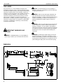
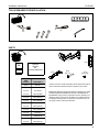
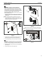
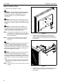
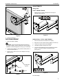
INSTALLATION INSTRUCTIONS
Instrucciones de instalación
Installationsanleitung
Instruções de Instalação
Istruzioni di installazione
Installatie-instructies
Instructions d´installation
Medium Flat Panel Wall Mount
Spanish Product Description
German Product Description
Portuguese Product Description
Italian Product Description
Dutch Product Description
French Product Description
CH-SJWD
CH-SJWD
Installation Instructions
DISCLAIMER
Sony Electronics, Inc., and its affiliated corporations and
subsidiaries (collectively, "Sony"), intend to make this manual
accurate and complete. However, Sony makes no claim that the
information contained herein covers all details, conditions or
variations, nor does it provide for every possible contingency in
connection with the installation or use of this product. The
information contained in this document is subject to change
without notice or obligation of any kind. Sony makes no
representation of warranty, expressed or implied, regarding the
information contained herein. Sony assumes no responsibility
for accuracy, completeness or sufficiency of the information
contained in this document.
CAUTION: A CAUTION alerts you to the possibility of
damage or destruction of equipment if you do not follow the
corresponding instructions.
WARNING: Failure to read, thoroughly understand, and
follow all instructions can result in serious personal injury,
damage to equipment, or voiding of factory warranty! It is the
installer’s responsibility to make sure all components are
properly assembled and installed using the instructions
provided.
WARNING: Failure to provide adequate structural strength
for this component can result in serious personal injury or
damage to equipment! It is the installer’s responsibility to
make sure the structure to which this component is attached
can support five times the combined weight of all equipment.
Reinforce the structure as required before installing the
component.
IMPORTANT WARNINGS AND
CAUTIONS!
WARNING: Exceeding the weight capacity can result in
WARNING: A WARNING alerts you to the possibility of
serious injury or death if you do not follow the instructions.
serious personal injury or damage to equipment! It is the
installer’s responsibility to make sure the combined weight of
all components located between the CH-SJWD mount up to
(and including) the display does not exceed 75 lbs (34 kg).
DIMENSION
516.87
20.35
215.90
8.50
152.40
6.00
307.72
12.11
215.90
8.50
81.77
3.22
68.25
2.69
231.52
9.11
26.20
1.03
100
3.94
100
3.94
220.66
8.69
373.33
14.70
120.65
4.75
2
Installation Instructions
CH-SJWD
LEGEND
Tighten Fastener
Pencil Mark
Apretar elemento de fijación
Marcar con lápiz
Befestigungsteil festziehen
Stiftmarkierung
Apertar fixador
Marcar com lápis
Serrare il fissaggio
Segno a matita
Bevestiging vastdraaien
Potloodmerkteken
Serrez les fixations
Marquage au crayon
Loosen Fastener
Drill Hole
Aflojar elemento de fijación
Perforar
Befestigungsteil lösen
Bohrloch
Desapertar fixador
Fazer furo
Allentare il fissaggio
Praticare un foro
Bevestiging losdraaien
Gat boren
Desserrez les fixations
Percez un trou
Phillips Screwdriver
Adjust
Destornillador Phillips
Ajustar
Kreuzschlitzschraubendreher
Einstellen
Chave de fendas Phillips
Ajustar
Cacciavite a stella
Regolare
Kruiskopschroevendraaier
Afstellen
Tournevis à pointe cruciforme
Ajuster
Open-Ended Wrench
Remove
Llave de boca
Quitar
Gabelschlüssel
Entfernen
Chave de bocas
Remover
Chiave a punte aperte
Rimuovere
Steeksleutel
Verwijderen
Clé à fourche
Retirez
By Hand
Optional
A mano
Opcional
Von Hand
Optional
Com a mão
Opcional
A mano
Opzionale
Met de hand
Optie
À la main
En option
Hex-Head Wrench
Security Wrench
Llave de cabeza hexagonal
Llave de seguridad
Sechskantschlüssel
Sicherheitsschlüssel
Chave de cabeça sextavada
Chave de segurança
Chiave esagonale
Chiave di sicurezza
Zeskantsleutel
Veiligheidssleutel
Clé à tête hexagonale
Clé de sécurité
3
Installation Instructions
CH-SJWD
TOOLS REQUIRED FOR INSTALLATION
#2
1/4"
PARTS
A (1)
B (1)
I/M
Interface
Bracket
Kit
(Including Hardware)
C (2)
x1
D (2)
3/8" x 3"
E (4)
8-32 x 3/8"
x1
JSBU
hardware
Sony Model #
C,D,S
KLH-26
C,D,S,F
FWD-32LX2
C,D,S,K
KLH-W32U
C,D,S,K
KDL-32N4000
C,D,S,K
KDL-32NL140
C,D,S,K
KDL-32M4000
C,D,S,K
KDL-37N4000
C,D,S,K
KDL-37NL140
C,D,S,K
KDL-37M4000
C,D,S,K
KLH-40X1
C,D,S,K
FWD-40LX2
C,D,S,K
FWD-40PX2
C,D,S,K
KDL-40SL140
- Refer to this list to assist in deciding which fasteners should be
used to install the interface bracket to specific Sony models.
IMPROPER INSTALLATION CAN LEAD TO DISPLAY FALLING
CAUSING SERIOUS PERSONAL INJURY OR DAMAGE TO
EQUIPMENT! Using screws of improper size may damage your
display! Properly sized screws will easily and completely thread
into display mounting holes. If spacers are required, be sure to
use longer screws of the same diameter.
4
Installation Instructions
CH-SJWD
INSTALLATION
WARNING: FAILURE TO PROVIDE ADEQUATE
STRUCTURAL STRENGTH FOR THIS MOUNT CAN
RESULT IN SERIOUS PERSONAL INJURY OR DAMAGE
TO EQUIPMENT! It is the installer’s responsibility to make
sure the structure to which this mount is attached can support
five times the combined weight of the mount and all
equipment attached to it. Reinforce the structure as required
before installing the mount.
1.
(B)
(A)
5
Determine location for mount keeping in mind display size,
extension, height adjustment (if applicable), and pitch/roll
requirements.
NOTE: Wall plate (B) MUST be installed into wood stud.
2.
Using wall plate (B) as a template, mark then drill two 1/8"
diameter pilot holes through top and bottom holes of wall
bracket into wall structure. (See Figure 1)
3
(D) x 2
6
2
Figure 2
7.
Tighten set screw in bottom of wall mount. (See Figure 3)
NOTE: Ensure set screw engages on back side of wall plate to
properly secure wall mount.
(B)
(A)
Figure 1
3.
Install two 3/8" x 3" hex head lag screws (D) through wall
plate (B) and drywall into wood stud. (See Figure 1)
4.
Ensure wall plate (B) is vertical, then tighten screws (D).
(B)
7
Set
Screw
CAUTION: Overtightening screws may cause wall bracket
to compress into soft wall surface, resulting in difficult mount
installation or improper engaging of set screw in later step.
5.
Insert top of wall mount (A) over lip on top of wall plate (B).
(See Figure 2)
6.
Swing wall mount down flush against wall.
Figure 3
5
CH-SJWD
Installation Instructions
DISPLAY INSTALLATION
1.
Determine mounting pattern on display.
WARNING: IMPROPER INSTALLATION CAN LEAD TO
EQUIPMENT FALLING CAUSING SERIOUS PERSONAL
INJURY AND DAMAGE TO EQUIPMENT! DO NOT
substitute hardware. Use only hardware supplied by
manufacturer!
1
WARNING: IMPROPER INSTALLATION CAN LEAD TO
ELECTRIC SHOCK OR DAMAGE TO EQUIPMENT! Screw
length must not exceed the depth of threaded mounting insert
in display.
WARNING: OVERTIGHTENING OF SCREWS CAN
x2
DAMAGE PARTS AND LEAD TO SERIOUS PERSONAL
INJURY AND DAMAGE TO EQUIPMENT! DO NOT over
tighten screws when installing interface bracket.
NOTE: If the display being installed has a 100x100 VESA
mounting pattern, no interface bracket is required and
the display can be mounted directly to the mounting
plate as outlined below.
Figure 4
2.
NOTE: If the display being installed requires an interface
bracket, refer to the interface bracket installation
instructions.
Align two screws in display back with upper teardrop
mounting holes in mounting plate and lower display until
screws are seated in lower area of teardrop mounting holes.
(See Figure 5)
WARNING: IMPROPER INSTALLATION CAN LEAD TO
DISPLAY FALLING CAUSING SERIOUS PERSONAL
INJURY OR DAMAGE TO EQUIPMENT! Using screws of
improper size may damage your display! Proper screws will
easily and completely thread into display mounting holes.
Ensure that screws are not too long.
2
2
WARNING: IMPROPER INSTALLATION CAN LEAD TO
DISPLAY FALLING CAUSING SERIOUS PERSONAL
INJURY OR DAMAGE TO EQUIPMENT! Inadequate thread
engagement in display may cause display to fall! Back out
screws ONLY as necessary to allow installation of mounting
plate!
1.
(A)
Start two M4 x 8mm Phillips pan head screws (included in
hardware kit) into upper mounting holes in display back.
(See Figure 4)
NOTE: Leave at least 1/8" of each screw protruding out back
of display.
Figure 5
3.
6
Install two more of the same screws through lower mounting
holes in display mounting plate and into display back.
(See Figure 6)
Installation Instructions
CH-SJWD
ADJUSTMENTS
x2
3
Swing Arm
PIVOT / SWING TENSION
1.
Slightly loosen or tighten the adjustment screw(s) as
necessary (See Figure 8).
1
Figure 8
Figure 6
4.
Tighten all hardware.
DISPLAY ROLL / PITCH / YAW TENSION:
CABLE MANAGEMENT
1.
1.
Disconnect all wires and cable from the display.
2.
Remove two Lower screws securing display to Centris cup.
CAUTION: Ensure that adequate cable slack exists for
3.
Loosen two Upper screws securing display.
movement of display, and that cables will not be pinched by
installation of cable management cover(s) (C) or screws (E).
4.
Lift display upward and away from mount.
5.
Turn the tension adjustment screw clockwise to increase
tension, or counter-clockwise to decrease tension.
(See Figure 9)
Attach all cables to display.
2.
Carefully insert cables in cavity located in lower portion of
mount arm (See Figure 7).
3.
Install cover (C) with two 8-32 x 3/8" Phillips screws (E).
(See Figure 7)
Cable Path
(typical)
2
5
(C) x 2
3
(E) x 4
Figure 9
Figure 7
Re-install display.
7
CH-SJWD
Installation Instructions
Sony Electronics Inc.
1 Sony Drive
Park Ridge, NJ 07656
201-930-1000
www.sony.com/displaysystems
8800-002044 Rev00
11/09