1
SERVICE
MANUAL
MOISTURE
BALANCE
HA 300
HA60
Precisa Instruments AG
HA 300
HA 60
HA 300 27.11.98
HA 60 27.11.98
INDEX
Contents
Inhalt
General Instructions / Allgemeine Hinweise
SECTION
REGISTER
B
- Wartung, mechanische Reparaturen
- Wechseln des EPROM / EEPROM
- Programmierung und Prüfung
- Temperaturkalibrierung
- Fehleranzeigen
- Testlauf
- Fernsteuerung
Precisa Instruments AG
B 01.01-02
B 02.01
B 03.01
F 1.1-2
F 2.1
F 3.1
C 01.01-08
G 1.1-7
D 01.01-02
D 02.01
D 03.01-03
D 04.01-02
D 05.01-02
D 06.01-02
D 07.01
H 1.1-2
H 2.1
H 3.1-3
H 4.1-2
H 5.1
H 6.1
H 7.1
E 01.01-02
E 02.01
E 03.01-03
E 04.01
E 05.01-02
E 06.01-02
E 07.01
I 1.1-2
I 2.1
I 3.1-3
I 4.1-2
I 5.1
I 6.1
I 7.1
C
D
- Service, mechanical repairs
- Exchanging of EPROM / EEPROM
- Program and testing
- Temperature calibration
- Error messages
- Test running
- Remote control
Einstellungen
PAGE
SEITE
A 02.01-02
- Main board / Hauptprint 350-7232-010
Adjustments
PAGE
SEITE
A 01.01-02
- Housing's top / Gehäuse Oberteil
- Housing's bottom / Gehäuse Unterteil
- Inward construction / Innenteil
Electronics / Elektronik
HA 60
A
- Upgrade-kit for Series 300 S
- Nachrüstsatz zu Serie 300 S
- Upgrade-kit for Series 300 SCS
- Nachrüstsatz zu Serie 300 SCS
Mechanics / Mechanik
HA 300
E
0.1
HA 300
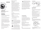
UPGRADE-KIT FOR SERIES 300 S
NACHRÜSTSATZ ZU SERIE 300 S
Upgrade-kit for series 300 S
Nachrüstsatz zu Serie 300 S
1
2
B
A
Key No.
Part No.
Description
Beschreibung
1
PN 1100-011
screw M3x6
ZK-Schraube M3x6
2
350-7127
cable
Kabel
PAG OERLIKON AG
A 01.01
HA 300
UPGRADE-KIT FOR SERIES 300 S
NACHRÜSTSATZ ZU SERIE 300 S
Assembling instructions for upgrade-kit HA 300 for series 300 S
1.
Disconnect the balance from the mains (pull out the mains-plug)
2.
Remove the weighing-pan and the pan-holder
3.
Remove the retention-ring and if mounted the cover-panel
4.
Remove the windshield if mounted
5.
Remove the dust-cover
6.
Loose the screw on the balance-top with a screwdriver no.4
7.
Lift the balance-top and disconnect the flat-wire [A]
8.
Remove the ovale cover-plate from the data-output opening in the rear of the balance
9.
Lead the cable [2] through the opening and fix the jack with two screws [1]
10. Lead the cable [2] through the cable-channel between the transformer and the partition-wall
11. Plug the plug to the pin-socket as shown on the page 1
12. Reassemble the balance (don't forget to connect the flat-wire [A] to the balance-top)
Einbauanleitung für Nachrüstsatz HA 300 zu Serie 300 S
1.
Waage vom Netz trennen (Netzstecker ziehen)
2.
Waagschale und Schalenträger entfernen
3.
Haltering und evtl. Deckblech entfernen
4.
evtl. Windschutz entfernen
5.
Staubschutzhülle entfernen
6.
Zylinderschraube am Waagenoberteil mit einem Schraubenzieher Nr. 4 lösen
7.
Waagenoberteil anheben und Flachbandkabel [A] lösen
8.
Ovale Datenausgang-Abdeckung auf der Rückseite der Waage entfernen
9.
Kabel [2] durch die Öffnung führen und Buchse mit zwei Schrauben [1] anschrauben
10. Kabel [2] durch den Kabelkanal zwischen Trafo und Gehäuse-Trennwand führen
11. Stecker des Kabels auf die Stiftleiste wie auf Seite 1 gezeigt stecken
12. Waage wieder zusammenbauen (Flachbandkabel [A] nicht vergessen anzuschliessen)
PAG OERLIKON AG
A 01.02
HA 300
UPGRADE-KIT FOR SERIES 300 SCS
NACHRÜSTSATZ ZU SERIE 300 SCS
Upgrade-kit for series 300 SCS
Nachrüstsatz zu Serie 300 SCS
1
2
D
C
B
A
Key No.
Part No.
Description
Beschreibung
1
PN 1100-011
screw M3x6
ZK-Schraube M3x6
2
350-7159
cable
Kabel
PAG OERLIKON AG
A 02.01
HA 300
UPGRADE-KIT FOR SERIES 300 SCS
NACHRÜSTSATZ ZU SERIE 300 SCS
Assembling instructions for upgrade-kit HA 300 for series 300 SCS
1.
Disconnect the balance from the mains (pull out the mains-plug)
2.
Remove the weighing-pan and the pan-holder
3.
Remove the retention-ring and if mounted the cover-panel
4.
Remove the windshield if mounted
5.
Remove the dust-cover
6.
Loose the screw on the balance-top with a screwdriver no.4
7.
Lift the balance-top and disconnect the flat-wire [A]
8.
Remove the ovale cover-plate from the data-output opening in the rear of the balance
9.
Lead the cable [2] through the opening and fix the jack with two screws [1]
10. Fix the cable channel [C]
11. Lead the cable [2] through the cable-channel [C] , bend the clip [D] 90°
12. Plug the plug to the pin-socket as shown on the page 1
13. Reassemble the balance (don't forget to connect the flat-wire [A] to the balance-top)
Einbauanleitung für Nachrüstsatz HA 300 zu Serie 300 SCS
1.
Waage vom Netz trennen (Netzstecker ziehen)
2.
Waagschale und Schalenträger entfernen
3.
Haltering und evtl. Deckblech entfernen
4.
evtl. Windschutz entfernen
5.
Staubschutzhülle entfernen
6.
Zylinderschraube am Waagenoberteil mit einem Schraubenzieher Nr. 4 lösen
7.
Waagenoberteil anheben und Flachbandkabel [A] lösen
8.
Ovale Datenausgang-Abdeckung auf der Rückseite der Waage entfernen
9.
Kabel [2] durch die Öffnung führen und Buchse mit zwei Schrauben [1] anschrauben
10. Kabelkanal [C] befestigen
11. Kabel [2] durch den Kabelkanal [C] führen, Klipp [D] 90° abbiegen
12. Stecker des Kabels auf die Stiftleiste wie auf Seite 1 gezeigt stecken
13. Waage wieder zusammenbauen (Flachbandkabel [A] nicht vergessen anzuschliessen)
PAG OERLIKON AG
A 02.02
HA 300
HOUSING'S TOP
GEHÄUSE OBERTEIL
Housing's top
Gehäuse Oberteil
2
1
3
4
5
5
6
2
8
7
11
14
10
9
12
13
10
11
PAG OERLIKON AG
B 01.01
HA 300
HOUSING'S TOP
GEHÄUSE OBERTEIL
Key No.
Part No.
Description
Bezeichnung
1
350-7120
ventilation-gatter
Lüftungsgitter
2
3
PN 3650-001
350-2023
ceramic-unit
hose-clamp
Einschubkeramik
Bride
4
5
PN 3650-002
350-7133
ceramic-unit
emitter compl.
Einschubkeramik
Strahler kpl.
6
7
350-2024
350-2022
emitter-plate
screen-cover
Strahlerblech
Blende
8
9
PN 1100-024
350-7118
screw M3x8
casing
ZK-SchraubeM3x8
Mantelblech
10
11
350-4052
350-4053
handle
cover-cap
Griff
Abdeckkappe
12
13
350-4060
350-4059
window inside
window outside
Sichtfenster innen
Sichtfenster aussen
14
350-7121
backwall
Rückwand
PAG OERLIKON AG
B 01.02
HA 300
HOUSING'S BOTTOM
GEHÄUSE UNTERTEIL
Housing's bottom
Gehäuse Unterteil
15
19
16
17
20
18
21
22
24
23
25
Key No.
Part No.
Description
Beschreibung
15
16
350-3052
F2-012
slide
pressure-spring
Stössel
Druckfeder
17
18
PN 1024-004
PN 1100-093
retention ring
set screw M3x4
Sicherungsscheibe
Gewindestift M3x4
19
20
350-8021
350-3048
temp.sensor
axis
Temperaturfühler
Achse
21
22
350-2025
350-4058
heat-shield
display-glass
Wärmeschild
Displayglas
23
24
350-4055
350-7119
keyboard-foil
top housing
Folientastatur
Aufsatzgehäuse
25
350-7130
ground-plate
Boden
PAG OERLIKON AG
B 02.01
HA 300
INWARD CONSTRUCTION
INNENTEIL
Inward construction
Innenteil
28
27
26
Key No.
Part No.
Description
Beschreibung
26
350-7165
damper weight group A
Ausgleichsgewicht Gruppe A
350-7117
350-7162
damper weight group M
damper weight group C
Ausgleichsgewicht Gruppe M
Ausgleichsgewicht Gruppe C
350-7141
350-8019
windshield
pan holder
Windschutz
Schalenträger
27
28
PAG OERLIKON AG
B 03.01
HA 300
PAG OERLIKON AG
MAIN BOARD 350-7232-010
HAUPTPRINT 350-7232-010
C 01.01
PAG OERLIKON AG
A
[
0
.
.
1
5
]
D
[
0
.
.
7
]
C
S
[
0
.
.
7
]
I
O
[
0
.
.
7
]
ALE
WR
RD
RES
TEMP-OUT
DATALINE
TXD
RXD
TXD
RXD
ELEKTRONIK
3572322.SCH
IO[0..7]
CS[0..7]
D[0..7]
A[0..15]
3572322
ALE
WR
RD
RES
TEMP-OUT
DATALINE
CONTROLLER
3572321.SCH
IO[0..7]
CS[0..7]
D[0..7]
A[0..15]
3572321
3572320.SCH 240694
HA 300
MAIN BOARD 350-7232-010
HAUPTPRINT 350-7232-010
C 01.02
PAG OERLIKON AG
11
A0
A1
A2
A3
A4
A5
A6
A7
A8
A9
A10
A11
A12
A13
A14
10
9
8
7
6
5
4
3
25
24
21
23
2
26
1
12
13
U7C
C10
1N4448
D1
3
6
7
2
1
U7A
4
5
C11
C5
0.1uF
GND
0.1uF
VBAT
GND
1
4
U1
D0
D1
D2
D3
D4
D5
D6
D7
Q0
Q1
Q2
Q3
Q4
Q5
Q6
Q7
INT0
INT1
T0
T1
RESET
X2
X1
EA/VP
15
14
13
12
11
10
9
7
8
9
10
74HC132
U5C
CS0
CS1
CS2
CS3
CS4
CS5
CS6
CS7
VCC
P1.0
P1.1
RD
P1.2
WR
P1.3
PSEN
P1.4
ALE/P
P1.5
TXD
P1.6
RXD 80C31 P1.7
P2.0
P2.1
P2.2
P2.3
P2.4
P2.5
P2.6
P2.7
U2
P0.0
P0.1
P0.2
P0.3
P0.4
P0.5
P0.6
P0.7
Y0
Y1
Y2
Y3
VCC
Y4
6 G1
4 G2A Y5
5 G2B Y6
Y7
74HC138
U3
1 A
2 B
3 C
74HC132
1
2
4
5
17
16
29
30
11
10
21
22
23
24
25
26
27
28
39
38
37
36
35
34
33
32
74HC132
U5A
U5B
A15
3
6
D0
D1
D2
D3
D4
D5
D6
D7
A8
A9
A10
A11
A12
A13
A14
A15
C8
0.1uF
A12
A13
A14
GND
VCC
GND
VCC
A0
A1
A2
A3
A4
A5
A6
A7
C7
0.1uF
2
5
6
9
12
15
16
19
1
11 OC
G
74HC373
3
4
7
8
13
14
17
18
VCC
D0
D1
D2
D3
D4
D5
D6
D7
GND
U7B
GND
D0
D1
D2
D3
D4
D5
D6
D7
VBAT
14
28
11
12
13
15
16
17
18
19
GND
0.1uF
R5 47K
9
10
D0
D1
D2
D3
D4
D5
D6
D7
GND
C6
VCC
11
12
13
15
16
17
18
19
74HC132
U8
A0
D0
A1
D1
D2
A2
A3
D3
D4
A4
A5
D5
A6
D6
D7
A7
A8
A9
A10
A11 VBAT
A12
A13
A14 GND
0.1uF
U7D
8
O0
O1
O2
O3
O4
O5
O6
O7
20
22 CE
OE/VPP
27C512
10
9
8
7
6
5
4
3
25
24
21
23
2
26
27
1
20 CS
27 WR
22 OE
62256
GND
GND
GND
A0
A1
A2
A3
A4
A5
A6
A7
A8
A9
A10
A11
A12
A13
A14
A15
U6
A0
A1
A2
A3
A4
A5
A6
A7
A8
A9
A10
A11
A12
A13
A14
A15
C1
R2
4K7
GND
TEMP-OUT
DATALINE
D[0..7]
A[0..15]
0.1uF
C2
RES
CS[0..7]
ALE
RXD
TXD
WR
RD
JP1
1
2
RS232
JP3
1
2
3
4
INTERRUPTS
IO[0..7]
JP2
1
2
3
4
5
6
7
8
P1
VCC
IO0
IO1
IO2
IO3
IO4
IO5
IO6
IO7
3572321.SCH 240694
7702A
U4
7 SI R1
5 R REF
3 CT RI
R3
4K7
0.47uF
2K7
VCC
6
1
2
I VCC
O
[
C9
0
.
0.1uF
.
7 GND
]
CS[0..7]
IO0
IO1
IO2
IO3
IO4
IO5
IO6
IO7
R4
2K
R1
VCC
1
2
3
4
5
6
7
8
12
13
14
15
9
11.0592 MHz
31 GND
C4
33pF
19
QZ1
GND
C3
18
33pF
A[0..15]
D[0..7]
HA 300
MAIN BOARD 350-7232-010
HAUPTPRINT 350-7232-010
C 01.03
PAG OERLIKON AG
D10
5V6
R16
1K
D4
1N4448
JP4
1
2
3
4
5
6
7
8
INTERFACE
C28
R17
1K
R6
56K
D2
1N4448
VCC
VCC
C14
3.3nF
IO0
IO1
+5V
GND
+15V
-15V
D5
1N4448
GND
D3
1N4448
GND
GND
VBAT
1K
C18
.1uF
R15
BT1
2.4V
6242
IO5
R44
DATALINE
1K
D11
C30
GND
5V6
47uF
47uF
D6
C29
VCC
47uF
C13 32.768kHz
BAT48
U13
22pF
17 QZ
4
22pF
A0
5
A1
C12 QZ2 16
6
WR
QZ
A2
10 WR
7
3 ALE A3
14
ALE
D0
2 CS0 D1 13
15 CS1 D2 12
RES
8
D3 11
18 RD
+VS
RD
GND
+5V
TXD
RXD
GND
7
6
5
CS[0..7]
A[0..15]
D[0..7]
IO[0..7]
RC
SCL
SDA
PCB8582
U10
1 A0
2 A1
3 A2
CS[0..7]
A[0..15]
D[0..7]
IO[0..7]
TEMP-OUT
IO6
IO0
IO2
IO3
IO4
1
OPEN
CS2
A0
A1
A2
A3
CS1
CS0
2
3
D0
D1
D2
D3
A0
A1
A2
A3
1
11
GND
MSW3P
GND
Q0
Q1
Q2
Q3
Q4
Q5
Q6
Q7
2
5
6
9
12
15
16
19
Q0
Q1
Q2
Q3
Q4
Q5
Q6
Q7
2
5
6
9
12
15
16
19
R7
R8
R9
HEATCTRL
3572324.SCH
DISPDATA
DISPCLK
GITTER-18
GITTER-19
GITTER-20
DISPBLK
DISPON
DISPEN
SUMMER
3572323.SCH
3572324
GND
VSS
123456789
R-NET1 8x4K7
3572322.SCH 240694
VCC
VCC
GND
VDD
+5V
JP6
1
2
3
4
5
6
7
8
INPUT
GND
JP5
1
2
3
4
5
6
7
8
KEYBOARD
OUTPUT
JP7
1
2
3
4
5
6
7
8
9 10
11 12
13 14
15 16
SUMMER
DISPLAY
HEIZUNG
R10
470R
R11
470R
470R
R12
470R
R13
470R
R14
470R
470R
C16
470R
OC
VCC
GND
CLK
D17
.1uF
D9
74HC374
ZEILE 0
D8
ZEILE 1
1N4448 ZEILE 2
D7
1N4448
ZEILE 3
1N4448
U11
1N4448
SPALTE 0
3
Q0 D0
SPALTE 1
4
Q1 D1
SPALTE 2
7
Q2 D2
SPALTE 3
8
Q3 D3 13
Q4 D4 14
Q5 D5 17
Q6 D6 18
Q7 D7
U12
D0
D1
D2
D3
D4
D5
D6
D7
1
OC 11
G
74HC373 VCC
C17
VCC
GND
.1uF
2
5
6
9
12
15
16
19
3
4
7
8
13
14
17
18
D0
D1
D2
D3
D4
D5
D6
D7
U9
D0
D1
D2
D3
D4
D5
D6
D7
1
11 OC
CLK
74HC374
3
4
7
8
13
14
17
18
D0
D1
D2
D3
D4
D5
D6
D7
GND
D0
D1
D2
D3
D4
D5
D6
D7
VCC
C15
GND
.1uF
TEMP-A
TEMP-B
TEMP-OUT
3572323
HA 300
MAIN BOARD 350-7232-010
HAUPTPRINT 350-7232-010
C 01.04
PAG OERLIKON AG
HEATCTRL
GND
C22
.1uF
R38
240/20PPM
C31
.1uF
220R
R41
2
1
R39
100R
3
2
OP77GP
6
-15V
IL410
U19
4
7
+15V
U18
4
6
JP8
1
2
PT-100
R43
+15V
GND
-15V
SK220P
1
2
HEATER
3
R42 1K
270R
U17
5 AG RC
Q2
TO810NJ
EARTH
LS
FHP
F1
1
3
TEMP_B
TEMP_A
TEMP_OUT
LS
LS
GS220P
MAINS
LS
TEMP-OUT
TEMP-A
TEMP-B
3572323.SCH 240694
2
6
0.47uF
7 C26
17
0.47uF
18 C27
13
0.47uF
14 C25
43K
15 R40
8
9
10
TL500REF
11 DG BO
B
16 V+ A
C
12 V- IO
1 SI RC
ZC
2 SR
3 RO ZC
4 RI II
GND-AGND
1
2
JUMPER 1
.1uF
C23
.1uF
C24
ANALOG GROUND
GND
HA 300
MAIN BOARD 350-7232-010
HAUPTPRINT 350-7232-010
C 01.05
PAG OERLIKON AG
SUMMER
DISPBLK
DISPDATA
DISPCLK
DISPEN
GITTER-20
GITTER-19
GITTER-18
DISPON
R23
11 6
5
180pF
2
4 1
1
4
GND
3
U15A
VCC
2
1
10K
5
4
U16B
4K7
R32
T5
.1uF
74HC00
Co1
T4
Ro1 2K2
3
4K7
4K7
74HC00
R35
U16A
R31
R30
T3
3x BC327
3x 10K
+5V
+5V
+5V
R33
R29
R34
100K
6
74HC00
U16C
10uF
C21
8
3
8
A
C
2
A
C
1
FG206D1A
AC2
13
12
74HC00
U16D
2
4
11
33K
R36
2
1
VCC
Q1
BC337
2
2
220R
R37
LS1
-30V
1
9
350-7129
D16
1N4448 QMB-111P
GND
2
5
222233333333334
111111111
R19 6 7 8 9 0 1 2 3 4 5 6 7 8 9 0 2 3 4 5 6 7 8 9 0 1 2 3 4 5 6 7 8
R18
OOOOOOOOOOOOOOOOOOOOOOOOOOOOOOO
R20 O
33322222222221111111111987654321
2
1098765432109876543210
-30V 3x
220K
V
MM58241
U14
C
B
D
C
L
L
I
D
S
K
K
S
11111111112222222222
3333
333
01234567890123456789576145332490278
GGGGGGGGGGG
P
21111111111GGGGGGGGGPPPPPPPPPPPPPPD
09876543210987654321RPNMKJHGFEDCDAP
DISPLAY1
AC1
1
TP1
1N4448
D15
L1 D14 V22
GND
D13 8V2
47uF
C20
GND
240-7108
-15V
TP2
240-7108
-30V
R27
2K2
R28 T2
1K BC327
1
Ro1 = -----------------------3572324.SCH 240694
f * 2 * Ln(3) * Co1
10
9
4011
10K
7
C19
GND
R24 R25+5V
D12
1N4448
8
-15V
10
4K7 10K
9
T1
PIN 7 -> -15V
R21
BC327
PIN 14 -> GND
4K7
4011S
-15V U15C
R2610K
GND 12
R22 13
U15D
U15B
HA 300
MAIN BOARD 350-7232-010
HAUPTPRINT 350-7232-010
C 01.06
HA 300
Position
Quantity
1
2
3
4
5
6
7
8
9
10
11
12
13
14
15
16
17
18
19
20
21
1
1
1
2
1
2
1
1
1
1
1
1
1
1
1
1
1
1
5
1
7
22
23
24
25
26
27
28
29
30
31
32
33
2
1
1
1
1
2
1
4
1
2
1
7
34
7
35
36
37
38
39
40
41
42
43
1
1
1
1
1
3
1
1
15
44
45
46
4
1
2
PAG OERLIKON AG
MAIN BOARD 350-7232-010
HAUPTPRINT 350-7232-010
Reference
Type
Part-No.
L1
U16
U3
U11, U1
U9
U5, U7
U15
U4
U2
U14
U8
U10
U13
U6
U17
U18
Q2
Q1
T1, T2, T3, T4, T5
D6
D1, D7, D8, D9
D12, D15, D16
D10, D11
D13
D14
U19
R39
R37, R41
R43
R15, R28, R42, R44
R4
R27, Ro1
R1
R2, R3, R21, R24,
R30, R31, R32
R23, R25, R26, R29,
R33, R34, R35
R36
R40
R5
R6
R22
R18, R19, R20
R38
R-NET1
C01, C2, C5, C6,
C7, C8, C9, C10,
C11, C15, C17, C18,
C22, C23, C24
C26, C1, C25, C27
C19
C12, C13
SPULE
74HC00
74HC138
74HC373
74HC374
74HC132
4011
7702A
80C31
MM58241
6264
PCB8582
6242
27C512
TL500 CJ
OP77GP
TRIAC-TO810NJ
BC337
BC327
BAT48
1N4448
240-7108
PN 3019-400
PN 3019-403
PN 3019-404
PN 3019-405
PN 3019-409
PN 3020-024
PN 3022-026
PN 3022-029
PN 3022-031
PN 3022-033
PN 3022-034
PN 3022-035
PN 3022-038
PN 3030-011
PN 3030-026
PN 3050-101
PN 3100-004
PN 3100-007
PN 3210-006
PN 3230-901
5V6
8V2
V22
MOC3041
100R
220R
270R
1K
2K
2K2
2K7
4K7
PN 3241-956
PN 3241-982
PN 3242-022
PN 3270-004
PN 3304-110
PN 3304-122
PN 3304-127
PN 3304-210
PN 3304-220
PN 3304-222
PN 3304-227
PN 3304-247
10K
PN 3304-310
33K
43K
47K
56K
100K
220K
240R/20PPM
8x4K7
0.1uF
PN 3304-333
PN 3304-343
PN 3304-347
PN 3304-356
PN 3304-410
PN 3304-422
PN 3305-124
PN 3360-005
PN 3401-410
0.47uF
180pF
22pF
PN 3401-447
PN 3418-118
PN 3419-022
C 01.07
HA 300
Position
Quantity
47
48
49
50
51
52
53
54
55
56
57
58
59
60
61
62
63
64
65
66
67
68
69
70
71
72
73
74
75
76
77
78
79
80
81
2
1
1
1
4
2
1
1
3
4
1
2
2
2
3
1
1
1
1
1
1
1
1
1
1
1
1
1
1
1
1
1
1
1
1
MAIN BOARD 350-7232-010
HAUPTPRINT 350-7232-010
Reference
Type
C3, C4
C14
C31
C21
C28, C20, C29, C30
ZU DISPLAY1
DISPLAY1
PRINT
ZU U4, U10, U18
ZU U5, U7, U15, U16
ZU U3
ZU U6, U8
ZU U2, U14
ZU U13, U17
ZU U1, U9, U11
JP8
JP5
JP4
ZU Q2
DFP_1
MAINS
HEATER
F1
ZU F1
HEATER
OPEN
LS1
ZU F1
33pF
3.3nF
0.1uF
10uF
47uF
DISPLAYSTÜTZE
ANZEIGERÖHRE HA300
LP-FR4 1,6mm
SOCKEL-8-POL
SOCKEL-14-POL
SOCKEL-16-POL
SOCKEL-28-POL
SOCKEL-40-POL
SOCKEL-18-POL
SOCKEL-20-POL
PT-100 (1X2)
KEYBOARD (1X8)
INTERFACE (2X4)
KUEHLKÖERPER 12K/W
DRAHTFÜHRUNG
PRINTSTECKER-220V
PRINTKLEMME-220V
SICHERUNGSHALTER
SICHERUNGSDECKEL
PRINTKLEMME 2-POL
MICROSWITCH
QMB-111P
SICHERUNG 3,15AT
ERDUNGSZEICHEN
SPULENKERN
DRAHTBRÜCKE RA1
DRAHTBRÜCKE 50mm
NICD-AKKU 2,4V / 60mAh
11.0592 MHz
32.768kHz
ZU L1
JUMPER 1
ZU L1
BT1
QZ1
QZ2
PAG OERLIKON AG
Part-No.
PN 3419-033
PN 3419-233
PN 3419-340
PN 3428-610
PN 3428-648
350-4054
350-7129
350-7232
PN 3500-900
PN 3500-902
PN 3500-903
PN 3500-904
PN 3500-905
PN 3500-907
PN 3500-908
PN 3504-302
PN 3504-308
PN 3504-327
PN 3510-104
PN 3510-111
PN 3602-107
PN 3602-108
PN 3602-109
PN 3602-110
PN 3602-112
PN 3603-013
PN 3607-001
PN 3612-315
PN 3650-007
PN 3680-001
PN 3713-001
PN 3715-050
PN 3850-003
PN 3881-008
PN 3881-009
C 01.08
HA 300
SERVICE / MECHANICAL REPAIRS
The numbers in brackets which are mentionned in this chapter are relating to the pages B 01.01, B
01.02 and B 02.01 of this manual.
Exchanging of the bottom (25)
1. Place the HA300 upside-down, i.e. with the ventilation-gatter (1) underneath.
2. Separate the top housing (24) from the ground-plate (25) with the four screws at the bottom and the two
screws at the rear .
3. Split the flat-cable of the keyboard-foil (23) as well as the plug of the temperature-sensor (19) from the
PCB.
4. Remove the backwall (14) with the two screws.
5. Detach the connection-cable of the terminal between HA300 top- and bottom case according operatingmanual page 37.
6. Install the new bottom.
7. Connect the flat-cable of the keyboard-foil and the plug of the temperature-sensor again to the PCB.
8. Connect the connection-cable according operating-manual page 37.
9. Remount the backwall.
10. Rebuild the HA300 again.
Exchanging of the temperature-sensor PT-100 (19)
Proceed according point 1 - 3 of "exchanging of the bottom"
4. Screw-out the temperature-sensor (19).
5. Screw-in the new temperature-sensor.
6. Connect the flat-cable of the keyboard-foil and the plug of the temperature-sensor again to the PCB.
7. Rebuild the HA300 again.
Testing the temperature-sensor to an accuracy of +/- 1 Ohm (~2.5°C) by using an Ohm-Meter
Temperature
[°C]
Resistance
[Ohm]
Temperature
[°C]
Resistance
[Ohm]
Temperature
[°C]
Resistance
[Ohm]
16
17
18
19
20
21
22
106.2
106.6
107.0
107.4
107.8
108.2
108.6
23
24
25
26
27
28
29
109.0
109.3
109.7
110.1
110.5
110.9
111.3
30
31
32
33
34
35
36
111.7
112.1
112.4
112.8
113.2
113.6
114.0
Exchanging of the limit-switch (15) (16)
Proceed according point 1 - 3 of "exchanging of the bottom"
4. Split the retention-ring (17) from the slide (15).
5. Extend the slide (15) with the pressure-spring (16).
6. Draw-in the new slide with the new pressure-spring and secure with the retention-ring.
7. Rebuild the HA300 again.
PAG OERLIKON AG
D 01.01
HA 300
SERVICE / MECHANICAL REPAIRS
Exchanging of the display-glass (22)
1. Split the keyboard-foil (23) completely from the top-housing (24).
2. Take-out the display-glass (22)
3. Remove any traces of glue from the top-housing by using some solvent.
4. Mount the new display-glass.
5. Guide the flat-cable of the keyboard-foil through the slit of the top-housing and glue-on the keyboard-foil.
Exchanging of the emitter (5)
1. Loose the screw (8) and remove the ventilation-gatter (1).
2. Dismantle the backwall (14) with the two screws.
3. Remove the terminals of the emitter-cables at the rear of the casing (9), according to operation manual
page 37.
4. Loose the two screws of the emitter-plate, swing-out the rack.
5. Dismantle the hose-clamp (3) at cable-side.
6. Extend both ceramic-units (2) at cable-side and remove the emitters (5).
7. Insert the new emitter and fix it with the ceramic-units.
8. Rescrew the hose-clamp (take care of the cable-position).
9. Guide the cables of the emitters through the slit at the rear of the casing to the terminals.
10. Swing-in again the rack and fix it.
11. Connect the cables according operation-manual page 37.
12. Remount the backwall and the ventilation-gatter.
Exchanging of the windows (12) (13)
1. Remove the two cover-caps (11) on one side.
2. Loose the two screws below and remove the handle (10).
3. Extend the windows (12) (13).
4. Draw-in the new windows (12 inside, 13 outside).
5. Insert the handle and fasten it with the screws.
6. Remount the cover-caps again.
Cleaning of the ventilation-gatter (1)
1. Loose the screw (8) and remove the ventilation-gatter (1).
2. Clean the ventilation-gatter.
3. Insert again the ventilation-gatter and fasten it with the screw.
PAG OERLIKON AG
D 01.02
HA 300
EXCHANGING OF EPROM / EEPROM
The numbers in brackets which are mentionned in this chapter are relating to the pages B 01.01, B
01.02 and B 02.01 of this manual.
Exchanging of the EPROM
1. Separate the HA300 from the balance.
2. Place the HA300 upside-down, i.e. with the ventilation-gatter (1) underneath.
3. Separate the top housing (24) from the ground-plate (25) with the four screws at the bottom and the two
screws at the rear .
4. Split the flat-cable of the keyboard-foil (23) as well as the plug of the temperature-sensor (19) from the
PCB.
5. Take-out the bottom (25) of the top-housing, and put it so, that you can see the PCB like the illustration
shows.
6. Exchange the current EPROM (position U6) with the new-one.
Attention: the mark of the EPROM has to be orientated the same way as all other IC's.
7. Rebuild the HA300 again, (don't forget the flat-cable and the plug of the temperature-sensor).
Exchanging of the EEPROM
Follow points 1. to 5. like "exchanging of the EPROM"
6. Exchange the current EEPROM (position U10) with the new-one.
Attention: the mark of the EEPROM has to be orientated the same way as all other IC's.
7. Rebuild the HA300 again, (don't forget the flat-cable and the plug of the temperature-sensor).
Error Messages
-"CLEAR MEMORY YES / NO" = new software in the HA300 which will erase, resp. new initializing the RAM.
Choose "YES" with the arrow-keys, then press "ENTER" in order to erase the memory.
"NO" and "ENTER" provides the message "SWITCH OFF", (the new software cannot be activated without
memory-erasing).
EPROM
EEPROM
PAG OERLIKON AG
D 02.01
HA 300
PROGRAM AND TESTING
Conditions, Tools
- A Service-Box has to be connected to the balance (Version 2.0 or higher).
- A Set-up resistor W 54-202 has to be present.
Set-up with a new PCB, respectly a new EEPROM
1. Switch-ON
2. As soon as the balance is ready for operation, switch on the service-box in the HA300-mode (see below *).
3. Display "TEMP. PARAMETERS LOST"
Press <ESC> key (on HA300 keyboard).
4. Display "TEMP.-CAL.-FACTOR LOST"
Press <ESC> key (on HA300 keyboard).
5. Display "REALTIME CLOCK ERROR" or "REALTIME CLOCK HALTED".
Set the clock in F-SET DATE AND TIME-DATE (DD.MM.YY) 22.06.94-TIME (HH.MM.SS) 10.45.00.
6. Display time and temperature, e.g. 13.00.00 TEMP. 0°C.
7. Set-up of the temperature-measuring, memorizing the calibration-factor (see E 03.02).
8. Testing the hardware (see E 03.03).
9. Switch the balance OFF / ON and pay attention to the following error-messages:
TEMP.-PARAMETERS LOST
TEMP.-CAL.-FACTOR LOST
10. Display of time and temperature, control of the temperature:
557...559 °C for resistor 300 Ohm
0 °C for resistor 100 Ohm (polarity sign is irrelevant).
If not correct, repeat the temperature-setting.
If additional errors are displayed, proceed according page E 05.01.
(mostly the <ESC> key is hepful).
* Switching ON and OFF of the HA300 MODE, display eights (program "3")
- Key <1> ==> switching-on the HA300-mode
- Key <2> ==> switching-off the HA300-mode
- Key <3> ==> displays "88888888888888888888" without points.
Precisa Instruments AG
D 03.01
HA 300
PROGRAM AND TESTING
Valid for Software version from: I00-040x-P00
Conditions, Tools
- A Service-Box has to be connected to the balance (Version 2.0 or higher).
- A Set-up resistor W 54-202 has to be present.
Set-up with a new PCB, respectly a new EEPROM
1. Switch-ON
2. As soon as the balance is ready for operation, switch on the service-box in the HA300-mode (see below *).
3. Display "TEMP. PARAMETERS LOST"
Press <ESC> key (on HA300 keyboard).
4. Display "TEMP.-CAL.-FACTOR LOST"
Press <ESC> key (on HA300 keyboard).
5. Display "REALTIME CLOCK ERROR" or "REALTIME CLOCK HALTED".
Set the clock in F-SET DATE AND TIME-DATE (DD.MM.YY) 22.06.94-TIME (HH.MM.SS) 10.45.00.
6. Set-up of the temperature-measuring, memorizing the calibration-factor (see E 03.02).
7. Testing the hardware (see E 03.03).
8. Switch the balance OFF / ON and pay attention to the following error-messages:
TEMP.-PARAMETERS LOST
TEMP.-CAL.-FACTOR LOST
9. Display of time and temperature, control of the temperature:
379...381 °C for resistor 300 Ohm
If not correct, repeat the temperature-setting.
If additional errors are displayed, proceed according page E 05.01.
(mostly the <ESC> key is hepful).
* Switching ON and OFF of the HA300 MODE, display eights (program "3")
- Key <1> ==> switching-on the HA300-mode
- Key <2> ==> switching-off the HA300-mode
- Key <3> ==> displays "88888888888888888888" without points.
Precisa Instruments AG
D 03.01/A
HA 300
PROGRAM AND TESTING
Set-up of the temperature-measurement, calibration-factor (program "2")
The programing is similar as the temperature set-up on the balance. But first of all the balance has to be
switched into the HA300-mode by using the Service-Box.
The error-messages "TEMP.PARAMETERS LOST" and "TEMP.-CAL.-FACTOR LOST" may be confirmed
with the <ESC> key.
Resistor 100 Ohm
- Connect the 100 Ohm resistor to JP8
according the sketch and subsequently
measure with key <1>
- Display unstable ==> measuring is running.
JP8
Pair of resistors
W 54-202
Mark
JP8
Resistor 300 Ohm
- Connect the 300 Ohm resistor to JP8
according the sketch and subsequently
measure with key <2>
- Display unstable ==> measuring is running.
Pair of resistors
W 54-202
JP8
Mark
Calculation and control
- Key <3> ==> calculation and memorizing (message: "PARAMETERS SAVED")
- Display resistor 300 Ohm
- Control If the resistor is inside of 300.00 + / - 0.10 (value is unstable); if not, start again with the 1st resistor
100 Ohm
Precisa Instruments AG
D 03.02
HA 300
PROGRAM AND TESTING
Memorizing of the temperature-calibrating-factor
- Key <4> ==> memorizing of the factor (message: "CAL.-FACTOR SAVED").
- Display Resistor 100 Ohm
Error-messages during the set-up:
- "RESISTOR VALUES BAD" = resistor out of tolerance.
==> measure again the resistor with key <1> or <2>.
- "MISSING RESISTORS" = missing values for the calculation
==> measure the resistor of 100 or 300 Ohm.
Hardware-Test (program "0")
For the following tests, the key <1> has always to be pressed !
Control of the display and the micro-switch
- releasing the micro-switch
==> Display "KEY= - OPEN"
- Pressing the micro-switch
==> Display "88888888888888888888" with points (all segments).
Control of the keyboard and the buzzer
- No key pressed
==> Display "KEY = - OPEN"
- Pressing a key
==> Display "KEY = "NAME" OPEN", the buzzer sounds for about 1 second.
Setup
Memory
Down
Precisa Instruments AG
Up
Insert
Unit
Function
Start
Clear
Escape
Enter
D 03.03
HA 300
TEMPERATURE CALIBRATION
General problem
If a probe is heated-up in the HA300, his temperature is higher as the settled value. The temperature of the
probe is dependent of the consistence of the material.
Temperature calibration
Preparation
1.
Put a aluminum pan in the dryer and tare the unit.
2.
Put the temperature calibration plate onto the aluminum pan. Keep attention to have the hole for the
temperature sensor on the right hand side.
3.
Set temperature in interval 1 (HA 300) resp. in HEAt-t (HA 60) at which you want to calibrate the
apparatus.
4.
Deactivate (-) all the other parameters (heating level, timer, minimum, interval 2 and 3, stop-mode)
resp. (HEAT-l, booSt, StoP, tiME).
5.
Start drying with the <START/STOP> Key.
6.
As soon as the dryer has started, place the external temperature sensor :
Put the temperature sensor through the hole in the second column of the right hand side of the
ventilation-gatter between the both ceramic-units and put it into the hole for the Sensor of the
calibration plate.
7.
Connect the temperature sensor to the measurement unit and switch it on.
HA 300 :
8.
Press the <F>-Key (see manual page 34)
9.
Get in via the password (Superuserkey 79145236) to “CAL.-TEMP:... °C”.
HA 60 :
8.
Press the <T>-Key (see manual page 32)
9.
Get in via the password “———PWD” (Superuserkey 791452) to “t-CAL nnn”.
Balancing
These steps are repeated until the temperature of the dryer agrees with that of the external temperature
sensor.
1.
2.
3.
4.
Wait until the temperature in both the dryer and the external temperature sensor is stable (> 15 min.)
Read off the temperature on the external temperature sensor.
Enter the temperature read off in the dryer by pressing <ENTER> and finish with <ENTER> again
The dryer is now regulating to the setted temperature again.
Clearing temperature calibration factor
The temperature calibration factor is reset to the value 1.0.
HA 300 :
After Step 9 of the preparation press the <CLR>-Key.
HA 60 :
After Step 9 of the preparation go to “t-CAL CLR” and press the <ENTER>-Key.
Precisa Instruments AG
D 04.01
HA 300
TEMPERATURE CALIBRATION
Temperature-Calibration starting with Software
HA 300 : I00-040x-P00
Preparation
1.
2.
3.
4.
5.
Put a aluminum pan in the dryer and tare the unit.
Put the temperature calibration plate onto the aluminum pan. Keep attention to have the hole for the
temperature sensor on the right hand side.
Close the Cover.
Put the temperature sensor through the hole in the second column of the right hand side of the
ventilation-gatter between the both ceramic-units and put it into the hole for the Sensor of the
calibration plate.
Connect the temperature sensor to the measurement unit and switch it on.
HA 300 :
6.
Press the <F>-Key (see manual page 34)
7.
Get in via the password (Superuser Key 79145236) zu “TEMP. CALIBRATION”..
PASSWORD ............ — TEMP. CALIBRATION
— START CALIBRATION
— TEST CALIBRATION
8.
Start the desired procedure with <ENTER>.
HA 60 :
6.
Press the <T>-Key (see manual page 32)
7.
Get in via the password “———PWD” (Superuserkey 791452) to “t-CAL SET”.
................... PWD
— t-CAL
SET
— StArtT-C
— tESt T-C
8.
Start the desired procedure with <ENTER>.
Tempearture Calibration
1.
2.
3.
4.
5.
6.
7.
The dryer is now regulating to 100°C during 15Min. (the display is flashing).
Wait until the display stops flashing (in the HA300 there is a sound signal).
Read off the temperature on the external temperature sensor.
Enter the temperature read off in the dryer by pressing <ENTER> and finish with <ENTER> again.
The dryer is now regulating to 160°C; wait until the display stops flashing.
Read off the temperature on the external temperature sensor.
Enter the temperature read off in the dryer by pressing <ENTER> and finish with <ENTER> again.
Test Tempearture Calibration
1.
2.
3.
4.
5.
6.
7.
The dryer is now regulating to 100°C during 15Min. (the display is flashing).
Wait until the display stops flashing (in the HA300 there is a sound signal).
Read off the temperature on the external temperature sensor and note it somewhere.
Pressing <ENTER>. The dryer is now regulating to 160°C; wait until the display stops flashing.
Read off the temperature on the external temperature sensor and note it somewhere.
Pressing <ENTER>.
Write your measured temperatures
Precisa Instruments AG
D 04.02
HA 300
ERROR MESSAGES
Error messages
Generalities
All hardware error messages of the HA300 are given in English.
1. Definitive fatal errors (the device is broken on hardware-sector, switch-off).
- "INTERNAL RAM ERROR " (Error 16) = internal RAM is defective (8031) (replace the microprocessor).
- "EXTERNAL RAM ERROR" (Error 17) = external RAM is defective (6242) (replace the RAM).
- "EPROM CHECK ERROR" (Error 18) = EPROM is defective (wrong checksum) (replace EPROM).
2. Fatal errors (can maybe solved by the operator)
- "INTERFACE CONNECTION"
= No connection to the balance (replace the microprocessor, evtl. the one
of the balance.
- "INTERFACE DATA ERROR"
= Bad connection to the balance (replace the microprocessor, evtl. the one
of the balance.
- "REALTIME CLOCK ERROR"
= The clock (6242) is running too fast (set clock in F - SET DATE AND
TIME).
- "REALTIME CLOCK HALTED"
= The clock (6242) is not running (set clock in F - SET DATE AND TIME).
- "TEMP. HARDWARE ERROR"
= No sensor connected or hardware failure (test the sensor, resistance
according table on page E 01.01 of this manual).
- "TEMP. OUT OF RANGE"
= Bad sensor connected (test the sensor, resistance according table on
page E 01.01 of this manual).
3. Errors programable through the factory (may be solved at PAG-programing)
- "EPROM ERROR 19"
= Wrong EPROM.
- "EEPROM ERROR 13"
= Internal fault.
- "EEPROM ERROR 14"
= Wrong EPROM
PAG OERLIKON AG
D 05.01
HA 300
ERROR MESSAGES
4. Running-time errors (confirm with <ESC> key)
- "BALANCE DATA NOT GET"
= Didn't receive the specific datas of the balance (switch OFF / ON the
device)
- "TEMP.PARAMETERS LOST"
= None or unvalid temperature set-up datas in the EEPROM (proceed to
temperature set-up).
- "TEMP.CAL.FACTOR LOST"
= None or invalid temperature calibration factor in the EEPROM (calibrate
the temperature-factor {in the temperature sector}
or in F - CAL.TEMP.-.-°C).
5. Operating errors (addition to operating manual page 35)
- "PRINTRATE IS ACTIVE /
CADENCE IMP.ACTIF"
= During an active measurement with a settled printrate in the protocol, the
output parameters may not be modified.
- "NO DATA AVAILABLE /
PAS DE DONNEES"
= No datas available for the manipulation (define a new article).
- "PASSWORD WRONG /
MOT INCORRECT"
= A wrong password was introduced (key-in correct password).
- "PASSWORD PROTECTED /
PROT.PAR MOT DE PASS"
= The manipulation is not possible without password-input (key-in ssword,
password, Superuser key 79145236).
- "MEMORY PROTECTED /
MEMOIRE PROTEGEE"
= Memory is write-protected.
- "WORK.STORE PROTECTED / = Current article is protected.
MEMO.TRAVAIL PROTEGE"
- "...PROTECTED / ...PROTEGE" = Memory is write-protected.
PAG OERLIKON AG
D 05.02
HA 300
TEST RUNNING
1. Preparation, conditions
1. The device is connected to a Citizen-printer. The Service-box is connected as well and the program 3 is
selected. The balance is settled at a Baudrate of 600 and parity even (Conf FCT).
2. The device was switched-on during the night (operating-temperature). The power-supply for the heating (on
the HA300) is connected.
2. Target of the control
1. The device is reaching, respectively exceeding the settled temperature within the selected time, and should
keep stable after the overshoot.
2. The weighing-drift may not overshoot the limit-value during the measuring.
3. Procedure of the finish-test of the HA300
3.1 Preparation
1. Switch-on
2. By pressing key 1 of the Service-box, activate the functions of the HA300.
3. By pressing key 6 of the Service-box, load the article for the finish-control (the HA300 will switch-off for a
short time and will switch-on again).
The drying-parameters in the SETUP-Menu are now settled as follows:
-*PARAMETER - * INTEVAL 1 - * TEMPERATURE 250 °C - * STOP MODE - * TIMER 30.1 Min.
All other drying-parameters are switched-off.
4. Lay-on the test-weight (approx. 0.9 g).
3.2 Measuring and control
1. Start the drying-process with the START / STOP key.
The device will now heating-up to the settled temperature and printing a measuring protocol.
2. On this protocol, check the following items:
- the temperature should reach 100 °C after 2 minutes, resp. overshoot 250 °C after 6 minutes.
- is the temperature stable at 250 °C?
- is the residue-weight remaining within the limit-values (+ / - 10 digit).
3.3 Setting-back of the device
1. By pressing key 5 of the Service-box, the memory will be erased and the FA 0 = ARTICLE 1 will be loaded
into the work-memory (the HA300 will switch-off for a short time and will switch-on again).
Control of the display: "hh.mm.ss TEMP - °C".
PAG OERLIKON AG
D 06.01
HA 300
TEST RUNNING
4. Procedure of the finish-test of the ORImat
4.1 Preparation
1. Switch-on
2. By pressing key 1 of the Service-box, activate the functions of the HA300.
3. By pressing key 6 of the Service-box, load the article for the finish-control (the HA300 will switch-off for a
short time and will switch-on again).
The drying-parameters in the SETUP-Menu are now settled as follows:
-*PARAMETER - * INTEVAL 1 - * TEMPERATURE 250 °C - * STOP MODE - * TIMER 30.1 Min.
All other drying-parameters are switched-off.
4. Lay-on the test-weight (approx. 0.9 g).
4.2 Measuring and control
1. Start the drying-process with the START / STOP key.
The device will now heating-up to the settled temperature and printing a measuring protocol.
2. On this protocol, check the following items:
- the temperature should reach 100 °C after 2 minutes, resp. overshoot 250 °C after 6 minutes.
- is the temperature stable at 250 °C?
- is the residue-weight remaining within the limit-values (+ / - 10 digit).
4.3 Setting-back of the device
1. By pressing key 5 of the Service-box, the memory will be erased and the first three articles are initialised
and will be loaded into UA 0 = DRYING 105 C into the work-memory (the HA300 will switch-off for a short
time and will switch-on again).
Control of the display: "DRYING 105 C".
PAG OERLIKON AG
D 06.02
HA 300
REMOTE CONTROL
Remote control
In order to send remote-control commands from the PC to the HA300, the balance has to be switched into the
drying-mode.
"IRTAE"
"IRTAD"
=
=
switching-on the drying-mode
switching-off the drying-mode
The dryer is working now with the same remote-control-commands as the balance (P0, P1,...)
PAG OERLIKON AG
D 07.01
HA 300
WARTUNG / MECHANISCHE REPARATUREN
Die in diesem Kapitel aufgeführten Nummern in Klammern beziehen sich auf die Seiten B 01.01,
B 01.02 und B 02.01 dieses Manuals
Wechseln des Bodens (25)
1. HA 300 mit dem Lüftungsgitter (1) nach unten aufstellen
2. Aufsatzgehäuse (24) mit vier Schrauben auf der Unterseite und zwei Schrauben auf der Rückseite vom
Boden (25) trennen
3. Flachbandkabel der Folientastatur (23) und Stecker des Temperaturfühlers (19) vom Print lösen
4. Rückwand (14) mit zwei Schrauben entfernen
5. Klemmen des Verbindungskabels zwischen HA 300-Ober- und Unterteil gemäss Bedienungsanleitung
Seite 37 lösen
6. Neuen Boden einsetzen
7. Flachbandkabel der Folientastatur und Stecker des Temperaturfühlers wieder am Print anschliessen
8. Verbindungskabel gemäss Bedienungsanleitung Seite 37 anschliessen
9. Rückwand wieder montieren
10. HA 300 wieder zusammenbauen
Wechseln des Temperaturfühlers PT-100 (19)
Punkt 1-3 gemäss "Wechseln des Bodens"
4. Temperaturfühler (19) herausschrauben
5. Neuen Temperaturfühler hineinschrauben
6. Flachbandkabel der Folientastatur (23) und Stecker des Temperaturfühlers wieder am Print anschliessen
7. HA 300 wieder zusammenbauen
Prüfung des Temperaturfühlers PT-100 mit einem Ohmmeter auf +/- 1 Ohm (~2.5°C) genau
Temperatur
[°C]
Widerstand
[Ohm]
Temperatur
[°C]
Widerstand
[Ohm]
Temperatur
[°C]
Widerstand
[Ohm]
16
17
18
19
20
21
22
106.2
106.6
107.0
107.4
107.8
108.2
108.6
23
24
25
26
27
28
29
109.0
109.3
109.7
110.1
110.5
110.9
111.3
30
31
32
33
34
35
36
111.7
112.1
112.4
112.8
113.2
113.6
114.0
Wechseln der Endschalterbetätigung (15) (16)
Punkt 1-3 gemäss "Wechseln des Bodens"
4. Sicherungsscheibe (17) vom Stössel (15) lösen
5. Stössel (15) mit Druckfeder (16) ausfahren
6. Neuen Stössel mit neuer Druckfeder wieder einfahren und mit Sicherungsscheibe sichern
7. HA 300 wieder zusammenbauen
PAG OERLIKON AG
E 01.01
HA 300
WARTUNG / MECHANISCHE REPARATUREN
Wechseln des Displayglases (22)
1. Folientastatur (23) vollständig vom Aufsatzgehäuse (24) entfernen
2. Displayglas (22) hinausnehmen
3. Klebstoffreste am Aufsatzgehäuse mit Lösungsmittel entfernen
4. Neues Displayglas einsetzen
5. Flachbandkabel der Folientastatur durch Schlitz am Aufsatzgehäuse führen und Folientastatur aufkleben
Wechseln der Strahler (5)
1. Schraube (8) lösen, Lüftungsgitter (1) entfernen
2. Rückwand (14) mit zwei Schrauben demontieren
3. Klemmen der Strahlerkabel an der Rückseite des Mantelbleches (9) gemäss Bedienungsanleitung Seite
37 lösen
4. Zwei Schrauben am Strahlerblech lösen und Einschubeinheit ausschwenken
5. Kabelseitige Bride (3) entfernen
6. Beide kabelseitigen Einschubkeramiken (2) ausfahren und Strahler (5) entfernen
7. Neue Strahler einsetzen und mit den Einschubkeramiken fixieren
8. Bride wieder anschrauben (auf Kabelverlegung achten)
9. Kabel der Strahler durch Schlitz im Mantelblech zu den Klemmen ziehen
10. Einschubeinheit wieder einfahren und befestigen
11. Kabel gemäss Bedienungsanleitung Seite 37 anschliessen
12. Rückwand und Lüftungsgitter montieren
Wechseln der Sichtfenster (12) (13)
1. Zwei Abdeckkappen (11) auf einer Seite entfernen
2. Darunterliegende Schrauben lösen und Griff (10) abnehmen
3. Sichtfenster (12,13) ausfahren
4. Neue Sichtfenster einfahren (12 innen, 13 aussen)
5. Griff einsetzen und festschrauben
6. Abdeckkappen wieder montieren
Reinigung des Lüftungsgitters (1)
1. Schraube (8) lösen und Lüftungsgitter (1) entfernen
2. Lüftungsgitter reinigen
3. Lüftungsgitter wieder einsetzen und festschrauben
PAG OERLIKON AG
E 01.02
HA 300
WECHSELN DES EPROM / EEPROM
Die in diesem Kapitel aufgeführten Nummern in Klammern beziehen sich auf die Seiten B 01.01,
B 01.02 und B 02.01 dieses Manuals.
Wechseln des EPROM's
1. HA 300 von der Waage trennen
2. HA 300 mit dem Lüftungsgitter (1) nach unten aufstellen
3. Aufsatzgehäuse (24) mit vier Schrauben auf der Unterseite und zwei Schrauben auf der Rückseite vom
Boden (25) trennen
4. Flachbandkabel der Folientastatur (23) und Stecker des Temperaturfühlers (19) vom Print lösen
5. Boden (25) aus dem Aufsatzbehäuse (24) heben und so abstellen, dass man den Print wie unten abgebildet vor sich hat
6. Altes EPROM (Position U6) gegen ein neues austauschen
Achtung: die Markierung des EPROM's muss in der gleichen Richtung wie die der anderen IC's schauen
7. HA 300 wieder zusammenbauen (Flachbandkabel und Stecker des Temperaturfühlers nicht vergessen)
Wechseln des EEPROM's
Punkt 1. bis 5. gleich wie "Wechseln des EPROM"
6. Altes EEPROM (Position U10) gegen ein neues austauschen
Achtung: die Markierung des EEPROM's muss in der gleichen Richtung wie die der anderen IC's schauen
7. HA 300 wieder zusammenbauen (Flachbandkabel und Stecker des Temperaturfühlers nicht vergessen)
Fehleranzeigen
- ‘CLEAR MEMORY YES/NO’ = Neue Software im HA 300, welche das RAM löschen bzw. neu initialisieren
muss
Mit den Pfeiltasten ‘YES’ wählen, dann ‘ENTER’ drücken, um das Memory zu löschen
‘NO’ und ‘ENTER’ ergibt die Anzeige ‘SWITCH OFF’ (die neue Software kann ohne die Memorylöschung
nicht betrieben werden)
EPROM
EEPROM
PAG OERLIKON AG
E 02.01
HA 300
PROGRAMMIERUNG UND PRÜFUNG
Voraussetzungen, Werkzeuge
- Eine Servicebox ist an die Waage angeschlossen (Version 2.0 oder höher)
- Der Abgleichwiderstand W 54-202 ist vorhanden
Ablauf mit einem neuen Print bzw. neuem EEPROM
1.
Einschalten
2.
Wenn die Waage betriebsbereit ist, mit der Servicebox in den HA300 Mode schalten (siehe E 03.01)
3.
Anzeige ‘TEMP. PARAMETERS LOST’
<ESC> - Taste drücken (auf Tastatur HA300)
4.
Anzeige ‘TEMP.-CAL.-FACTOR LOST’
<ESC> - Taste drücken (auf Tastatur HA300)
5.
Anzeige ‘REALTIME CLOCK ERROR’ oder ‘REALTIMECLOCK HALTED’
Uhr stellen in F — SET DATE AND TIME — DATE [DD.MM.YY] 22.06.94 — TIME [HH.MM.SS]
10.45.00
6.
Anzeige Zeit und Temperatur Bsp.: ’13.00.00 TEMP. 0°C’
7.
Abgleichen der Temperaturmessung, Kalibrierfaktor speichern (siehe E 03.02)
8.
Hardware Testen (siehe E 03.03)
9.
Waage aus/einschalten und auf folgende Fehlermeldungen achten :
TEMP. PARAMETERS LOST
TEMP.-CAL.-FACTOR LOST
10. Anzeige von Zeit und Temperatur, Kontrolle der Temperatur :
557..559 °C für Widerstand 300 Ohm
0 °C für Widerstand 100 Ohm (Vorzeichen egal)
Falls nicht korrekt Temperaturabgleich wiederholen
Bei Anzeige zusätzlicher Fehler entsprechend den Angaben auf Seite E 05.01 verfahren
(oft hilft die <ESC> - Taste)
Ein- und Ausschalten des HA300 MODE, Achten anzeigen (Programm ‘3’)
- Taste <1> ==> HA300 Mode einschalten
- Taste <2> ==> HA300 Mode ausschalten
- Taste <3> ==> Anzeige ‘88888888888888888888’ ohne Punkte
Precisa Instruments AG
E 03.01
HA 300
PROGRAMMIERUNG UND PRÜFUNG
Gültig ab Software Version: I00-040x-P00
Voraussetzungen, Werkzeuge
- Eine Servicebox ist an die Waage angeschlossen (Version 2.0 oder höher)
- Der Abgleichwiderstand W 54-202 ist vorhanden
Ablauf mit einem neuen Print bzw. neuem EEPROM
1.
Einschalten
2.
Wenn die Waage betriebsbereit ist, mit der Servicebox in den HA300 Mode schalten (siehe E 03.01)
3.
Anzeige ‘TEMP. PARAMETERS LOST’
<ESC> - Taste drücken (auf Tastatur HA300)
4.
Anzeige ‘TEMP.-CAL.-FACTOR LOST’
<ESC> - Taste drücken (auf Tastatur HA300)
5.
Anzeige ‘REALTIME CLOCK ERROR’ oder ‘REALTIMECLOCK HALTED’
Uhr stellen in F — SET DATE AND TIME — DATE [DD.MM.YY] 22.06.94 — TIME [HH.MM.SS]
10.45.00
6.
Abgleichen der Temperaturmessung, Kalibrierfaktor speichern (siehe E 03.02)
7.
Hardware Testen (siehe E 03.03)
8.
Waage aus/einschalten und auf folgende Fehlermeldungen achten :
TEMP. PARAMETERS LOST
TEMP.-CAL.-FACTOR LOST
9.
Anzeige von Zeit und Temperatur, Kontrolle der Temperatur :
379...381 °C für Widerstand 300 Ohm
Falls nicht korrekt Temperaturabgleich wiederholen
Bei Anzeige zusätzlicher Fehler entsprechend den Angaben auf Seite E 05.01 verfahren
(oft hilft die <ESC> - Taste)
Ein- und Ausschalten des HA300 MODE, Achten anzeigen (Programm ‘3’)
- Taste <1> ==> HA300 Mode einschalten
- Taste <2> ==> HA300 Mode ausschalten
- Taste <3> ==> Anzeige ‘88888888888888888888’ ohne Punkte
Precisa Instruments AG
E 03.01/A
HA 300
PROGRAMMIERUNG UND PRÜFUNG
Abgleich der Temperaturmessung, Kalibrierfaktor (Programm ‘2’)
Die Programmierung erfolgt ähnlich wie der Temperaturabgleich bei der Waage. Vorher muss jedoch die Waage
mit der Servicebox in den HA300 Mode gesetzt werden.
Die Fehlermeldungen ‘TEMP. PARAMETERS LOST’ und ‘TEMP.-CAL.-FACTOR LOST’ können mit der
<ESC> - Taste bestätigt werden.
Widerstand 100 Ohm
- Widerstand 100 Ohm gemäss Skizze an JP8
anschliessen und mit Taste <1> messen
- Unruhige Anzeige ==> Messung läuft
JP8
Widerstandspaar
W 54-202
Markierung
JP8
Widerstand 300 Ohm
- Widerstand 300 Ohm gemäss Skizze an JP8
anschliessen und mit Taste <2> messen
- Unruhige Anzeige ==> Messung läuft
Widerstandspaar
W 54-202
JP8
Markierung
Berechnung und Kontrolle
- Taste <3> ==> Berechnung und Abspeicherung (Meldung : ‘PARAMETERS SAVED’)
- Anzeige Widerstand 300 Ohm
- Kontrolle Widerstand innerhalb 300.00 +/-0.10 (Wert ist unruhig) falls nicht, wieder bei 1.Widerstand 100 Ohm
beginnen
Precisa Instruments AG
E 03.02
HA 300
PROGRAMMIERUNG UND PRÜFUNG
Abspeichern des Temperatur-Kalibrier-Faktors
- Taste <4> ==> Faktor abspeichern (Meldung : ‘CAL.-FACTOR SAVED’)
- Anzeige Widerstand 300 Ohm
Fehlermeldungen während dem Abgleich:
- ‘RESISTOR VALUES BAD’ = Widerstand ausserhalb Toleranz
==> Widerstand mit Taste <1> oder Taste <2> nochmals messen
- ‘MISSING RESISTORS’ = Fehlende Werte für die Berechnung
==> Widerstand 100 Ohm und oder Widerstand 300 Ohm messen
Hardwaretest (Programm ‘0’)
Für die folgenden Tests muss die Taste <1> immer gedrückt sein !
Kontrolle der Anzeige und des Mikroschalters
- Mikroschalter losgelassen
==> Anzeige ‘KEY= — OPEN ‘
- Drücken des Mikroschalters
==> Anzeige ‘88888888888888888888’ mit Punkten (alle Segmente)
Kontrolle der Tastatur und des Summers
- Keine Taste gedrückt
==> Anzeige ‘KEY= —
OPEN ‘
- Drücken einer Taste
==> Anzeige ‘KEY= “NAME” OPEN ‘, Summer summt ca. 1 Sekunde
Setup
Memory
Down
Precisa Instruments AG
Up
Insert
Unit
Function
Start
Clear
Escape
Enter
E 03.03
HA 300
TEMPERATURKALIBRIERUNG
Allgemeines Problem
Wenn man eine Probe im HA 300 aufheizt, erreicht sie eine höhere Temperatur als die eingestellte Temperatur. Die Probentemperatur ist also vom Material der Probe abhängig.
Temperaturkalibrierung
Vorbereitung
1.
Legen Sie eine Alu-Schale in den Trockner und Tarieren Sie das Gerät.
2.
Legen Sie die Temperaturkalibrierplatte auf die Alu-Schale. Achten Sie darauf, dass die seitliche Bohrung, wo der Sensor eingesteckt wird, nach rechts zeigt.
3.
Stellen Sie im Intervall 1 (HA 300) resp. in HEAt-t (HA 60) die Temperatur ein, bei welcher Sie die
Kalibrierung vornehmen möchten
4.
Schalten Sie alle anderen Parameter aus (Hitzestufe, Timer, Minimum, Interval 2 und 3, Stop mode)
resp. (HEAT-l, booSt, StoP, tiME).
5.
Starten Sie den Trockner mit der <START/STOP>-Taste.
6.
Sobald der Trockner gestartet hat wird der externe Temperatur-Sensor eingeführt :
Stecken Sie dazu den Sensor in der zweiten Lochreihe von rechts zwischen den beiden Einschub
keramiken von oben durch das Lüftungsgitter und stecken ihn in die seitliche Bohrung der
Temperaturkalibrierplatte.
7.
Schliessen Sie den Temperatur-Sensor an das Messgerät an und schalten Sie dieses ein.
HA 300 :
8.
Drücken Sie die <F>-Taste (siehe Seite 34 der Bedienungsanleitung)
9.
Gehen Sie über dass Passwort in 'CAL.-TEMP. ... °C' (Superuser Key 79145236)
HA 60 :
8.
Drücken Sie die <T>-Taste (siehe Seite 32 der Bedienungsanleitung)
9.
Gehen Sie über dass Passwort “———PWD” (Superuser Key 791452) zu “t-CAL nnn”.
Einstellung
Diese Schritte werden solange wiederholt, bis die Temperatur im Trockner mit derjenigen des externen
Sensors übereinstimmt.
1.
2.
3.
4.
Warten Sie bis die Temperatur im Trockner und die des Temperatur-Sensors stabil sind (> 15 Min.).
Lesen Sie die Temperatur des Temperatur-Sensors ab.
Drücken Sie <ENTER> und stellen Sie die abgelesene Temperatur am Trockner ein; beenden Sie die
Eingabe mit <ENTER>.
Der Trockner regelt nun wieder auf die eingestellte Temperatur.
Löschen des Temperaturkalibrier-Faktors
Der Temperaturkalibrier-Faktor wird auf 1.0 gesetzt.
HA 300 :
Nach Schritt 9 der Vorbereitung wird die <CLR>-Taste gedrückt.
HA 60 :
Nach Schritt 9 der Vorbereitung gehen Sie zu “t-CAL CLR” und drücken die <ENTER>-Taste.
Precisa Instruments AG
E 04.01
HA 300
TEMPERATURKALIBRIERUNG
Temperatur-Kalibrierung ab Software
HA 300 : I00-040x-P00
Vorbereitung
1.
2.
3.
4.
5.
Legen Sie eine Alu-Schale in den Trockner und Tarieren Sie das Gerät.
Legen Sie die Temperaturkalibrierplatte auf die Alu-Schale. Achten Sie darauf, dass die seitliche Boh
rung, wo der Sensor eingesteckt wird, nach rechts zeigt.
Schliessen Sie die Haube.
Stecken Sie den Sensor in der zweiten Lochreihe von rechts zwischen den beiden Einschub
keramiken von oben durch das Lüftungsgitter und stecken ihn in die seitliche Bohrung der
Temperaturkalibrierplatte.
Schliessen Sie den Temperatur-Sensor an das Messgerät an und schalten Sie dieses ein.
HA 300 :
6.
Drücken Sie die <F>-Taste (siehe Seite 34 der Bedienungsanleitung)
7.
Gehen Sie über dass Passwort (Superuser Key 79145236) zu “TEMP. KALIBRIERUNG”.
PASSWORT ............ — TEMP. KALIBRIERUNG
— START KALIBRIERUNG
— TEST KALIBRIERUNG
8.
Starten Sie mit <ENTER> den gewünschten Ablauf.
HA 60 :
6.
Drücken Sie die <T>-Taste (siehe Seite 32 der Bedienungsanleitung)
7.
Gehen Sie über dass Passwort “———PWD” (Superuser Key 791452) zu “t-CAL SET”.
................... PWD
— t-CAL
SET
— StArtT-C
— tESt T-C
8.
Starten Sie mit <ENTER> den gewünschten Ablauf.
Temperatur Kalibrierung
1.
2.
3.
4.
5.
6.
7.
Der HA300 / HA60 heizt während 15Min. auf 100°C auf (Anzeige blinkt).
Warten Sie bis die Anzeige aufhört zu blinken (im HA300 ertönt ein Signalton).
Lesen Sie die Temperatur des Temperatur-Sensors ab.
Drücken Sie <ENTER> und stellen Sie die abgelesene Temperatur am Trockner ein; beenden Sie die
Eingabe mit <ENTER>.
Der HA300 / HA60 heizt nun auf 160°C; warten Sie bis die Anzeige aufhört zu blinken.
Lesen Sie die Temperatur des Temperatur-Sensors ab.
Drücken Sie <ENTER> und stellen Sie die abgelesene Temperatur am Trockner ein; beenden Sie die
Eingabe mit <ENTER>.
Test der Temperatur Kalibrierung
1.
2.
3.
4.
5.
6.
7.
Der HA300 / HA60 heizt während 15Min. auf 100°C auf (Anzeige blinkt).
Warten Sie bis die Anzeige aufhört zu blinken (im HA300 ertönt ein Signalton).
Lesen Sie die Temperatur des Temperatur-Sensors ab und notieren Sie sich diesen Wert.
Drücken Sie <ENTER>. Der HA300 / HA60 heizt nun auf 160°C; warten Sie bis die Anzeige aufhört
zu blinken.
Lesen Sie die Temperatur des Temperatur-Sensors ab und notieren Sie sich diesen Wert.
Drücken Sie <ENTER>.
Nun können Sie die notierten Werte in das ausgedruckte Protokoll eintragen.
Precisa Instruments AG
E 04.02
HA 300
FEHLERANZEIGEN
Fehlermeldungen
Allgemeines
Alle hardwareseitigen Fehlermeldungen des HA 300 werden in Englisch ausgegeben
1. Definitiv fatale Fehler (Gerät Hardwaremässig defekt, ausschalten)
- ‘INTERNAL RAM ERROR’ (Error 16) = Internes RAM defekt (8031) (Mikroprozessor ersetzen)
- ‘EXTERNAL RAM ERROR’ (Error 17) = Externes RAM defekt (6242) (RAM ersetzen)
- ‘EPROM CHECK ERROR’ (Error 18) = EPROM defekt (Checksumme falsch) (EPROM ersetzen)
2. Fatale Fehler (evtl. durch Bediener behebbar)
- ‘INTERFACE CONNECTION’
= Keine Verbindung mit der Waage (Mikroprozessor wechseln, evtl.
den der Waage
- ‘INTERFACE DATA ERROR’
= Schlechte Verbindung mit der Waage (Mikroprozessor wechseln,
evtl. den der Waage)
- ‘REALTIME CLOCK ERROR’
= Uhr (6242) läuft zu schnell (Uhr stellen in F — SET DATE AND
TIME)
- ‘REALTIMECLOCK HALTED’
= Uhr (6242) steht still (Uhr stellen in F — SET DATE AND TIME)
- ‘TEMP. HARDWARE ERROR’
= Kein Fühler angeschlossen oder Hardware defekt (Fühler testen,
Widerstand gemäss Tabelle auf Seite E 01.01 dieses Manuals)
- ‘TEMP. OUT OF RANGE’
= Schlechter Fühler angeschlossen (Fühler testen, Widerstand
gemäss Tabelle auf Seite E 01.01 dieses Manuals)
3. Factory programmierbare Fehler (durch PAG-Programmierung behebbar)
- ‘EPROM ERROR 19 nnn’
= Falsches EPROM
- ‘EEPROM ERROR 13’
= Interner Fehler
- ‘EEPROM ERROR 14’
= Falsches EPROM
PAG OERLIKON AG
E 05.01
HA 300
FEHLERANZEIGEN
4. Laufzeitfehler (mit <ESC> - Taste bestätigen)
- ‘BALANCE DATA NOT GET’
= Waagespezifische Daten nicht empfangen
(Gerät aus/ein schalten)
- ‘TEMP. PARAMETERS LOST’
= Keine oder ungültige Temperaturabgleichdaten im EEPROM
(Temperaturmessung abgleichen)
- ‘TEMP.-CAL.-FACTOR LOST’
= Kein oder ungültiger Temperaturkalibrierfaktor im EEPROM
(Temperaturkalibrierfaktor abgleichen (im Temperaturabgleich)
oder in F — CAL.TEMP. —.- °C)
5. Bedienungsfehler (Zusatz zur Bedienungsanleitung Seite 35)
- 'PRINTRATE IS ACTIVE /
CADENCE IMP. ACTIF'
= Bei aktiver Messung mit einer Printrate im Protokoll können die
Ausgabeparameter nicht verändert werden
- 'NO DATA AVAILABLE /
PAS DE DONNEES'
= Für die Manipulation sind keine Daten
vorhanden (neuen Artikel definieren)
- 'PASSWORD WRONG /
MOT INCORRECT'
= Falsches Passwort eingegeben (richtiges Passwort eingeben)
- 'PASSWORD PROTECTED /
PROT. PAR MOT DE PASS'
= Manipulation ohne Passworteingabe nicht möglich
(Passwort eingeben, Superuser Key 79145236)
- 'MEMORY PROTECTED /
MEMOIRE PROTEGE'
= Speicher ist schreibgeschützt
- 'WORK.-STORE PROTECTED /
MEMO. TRAVAIL PROTEGE'
= Aktiver Artikel ist schreibgeschützt
- '... PROTECTED / ... PROTEGE'
= Speicher ist schreibgeschützt
PAG OERLIKON AG
E 05.02
HA 300
TESTLAUF
1. Vorbereitung, Voraussetzung
1. Das Gerät ist mit einem Citizen-Drucker verbunden. Die Servicebox ist angeschlossen und das Programm
3 eingestellt. Die Waage ist auf Baudrate 600 und Parität Even eingestellt (Conf FCT).
2. Das Gerät war bereits übernacht am Netz angeschlossen (Betriebstemperatur). Die Stromversorgung für
die Heizung (am HA300) ist vorhanden.
2. Ziel der Kontrolle
1. Das Gerät erreicht bzw. überschreitet eine vorgegebenen Temperatur innerhalb der vorgegebenen Zeit
und stabilisiert sich nach dem Einschwingen auf der eingestellten Temperatur.
2. Die Gewichtsdrift darf während der Messung den Grenzwert nicht überschreiten.
3. Ablauf der Endkontrolle für den HA300
3.1 Vorbereitung
1. Einschalten
2. Mit der Taste 1 der Servicebox die Funktionen für den HA300 aktivieren.
3. Mit der Taste 6 der Servicebox den Artikel für die Endkontrolle laden (der HA300 schaltet kurz aus und
wieder ein).
Die Trocknungsparameter im Menü SETUP sind jetzt wie folgt eingestellt :
— *PARAMETER — *INTERVAL 1 — *TEMPERATURE 250 °C — *STOP MODE — *TIMER 30.1 Min.
Alle anderen Trocknungsparameter sind ausgeschaltet.
4. Das Prüfgewicht (ca. 0.9g) auflegen.
3.2 Messung und Kontrolle
1. Die Trocknung mit der START/STOP -Taste starten.
Das Gerät heizt nun auf die eingestellte Temperatur und druckt ein Messprotokoll aus.
2. Auf dem Messprotokoll folgenden Punkte kontrollieren :
- hat die Temperatur nach 2 Min. 100 °C erreicht bzw. nach 6 Min. 250 °C überschritten
- hat sich die Temperatur auf 250°C stabilisiert
- ist das Restgewicht während der Messung innerhalb der Grenzwerte geblieben (+ / - 10 Digit)
3.3 Gerät zurücksetzen
1. Durch drücken der Taste 5 der Servicebox wird das Memory gelöscht und der FA 0 = DEMO ARTICLE 1 in
den Arbeitsspeicher geladen (der HA300 schaltet kurz aus und wieder ein).
Kontrolle der Anzeige : ‘ hh.mm.ss TEMP. ___°C’.
PAG OERLIKON AG
E 06.01
HA 300
TESTLAUF
4. Ablauf der Endkontrolle für den ORImat
4.1 Vorbereitung
1. Einschalten
2. Mit der Taste 1 der Servicebox die Funktionen für den HA300 aktivieren.
3. Mit der Taste 6 der Servicebox den Artikel für die Endkontrolle laden (der HA300 schaltet kurz aus und
wieder ein).
Die Trocknungsparameter im Menü SETUP sind jetzt wie folgt eingestellt :
— *PARAMETER — *INTERVAL 1 — *TEMPERATURE 250 °C — *STOP MODE — *TIMER 30.1 Min.
Alle anderen Trocknungsparameter sind ausgeschaltet.
4. Das Prüfgewicht (ca. 0.9g) auflegen.
4.2 Messung und Kontrolle
1. Die Trocknung mit der START/STOP -Taste starten.
Das Gerät heizt nun auf die eingestellte Temperatur und druckt ein Messprotokoll aus.
2. Auf dem Messprotokoll folgenden Punkte kontrollieren :
- hat die Temperatur nach 2 Min. 100 °C erreicht bzw. nach 6 Min 250 °C überschritten
- hat sich die Temperatur auf 250°C stabilisiert
- ist das Restgewicht während der Messung innerhalb der Grenzwerte geblieben (+ / - 10 Digit)
4.3 Gerät zurücksetzen
1. Durch drücken der Taste 5 der Servicebox wird das Memory gelöscht, die ersten drei Artikel initialisiert und
der UA 0 = TROCKNUNG 105 C in den Arbeitsspeicher geladen (der HA300 schaltet kurz aus und wieder
ein).
Kontrolle der Anzeige : ‘TROCKNUNG 105 C’.
PAG OERLIKON AG
E 06.02
HA 300
FERNSTEUERUNG
Fernsteuerung
Um Fernsteuerbefehle direkt vom PC an den HA 300 zu senden, muss die Waage in den Trockner-Mode
geschaltet werden:
'IRTAE'
'IRTAD'
=
=
schaltet Trockner-Mode ein
schaltet Trockner-Mode aus
Der Trockner arbeitet dann mit den selben Fernsteuerbefehlen wie die Waage (P0, P1, ...)
PAG OERLIKON AG
E 07.01
HA 60
HOUSING'S TOP
GEHAUSE OBERTEIL
Housing's top
Gehäuse Oberteil
2
1
3
4
5
5
6
2
8
7
11
12
10
9
10
11
Precisa Instruments AG
F 1.1
HA 60
HOUSING'S TOP
GEHAUSE OBERTEIL
Key No.
Part No.
Description
Bezeichnung
1
350-7120
ventilation-gatter
Lüftungsgitter
2
3
PN 3650-001
350-2023
ceramic-unit
hose-clamp
Einschubkeramik
Bride
4
5
PN 3650-002
350-7133
ceramic-unit
emitter compl.
Einschubkeramik
Strahler kpl.
6
7
350-2024
350-2022
emitter-plate
screen-cover
Strahlerblech
Blende
8
9
PN 1100-024
350-7169
screw M3x8
casing
ZK-SchraubeM3x8
Mantelblech
10
11
350-4052
350-4053
handle
cover-cap
Griff
Abdeckkappe
12
350-7121
backwall
Rückwand
Precisa Instruments AG
F 1.2
HA 60
HOUSING'S BOTTOM
GEHAEUSE UNTERTEIL
Housing's bottom
Gehäuse Unterteil
15
19
16
17
20
18
21
23
22
24
Key No.
Part No.
Description
Beschreibung
15
16
350-3052
F2-012
slide
pressure-spring
Stössel
Druckfeder
17
18
PN 1024-004
PN 1100-093
retention ring
set screw M3x4
Sicherungsscheibe
Gewindestift M3x4
19
20
350-8021
350-3048
temp.sensor
axis
Temperaturfühler
Achse
21
22
350-2041
350-4079
heat-shield
decor-foil
Wärmeschild
Dekorfolie
23
24
350-7168
350-7130
top housing
ground-plate
Aufsatzgehäuse
Boden
Precisa Instruments AG
F 2.1
HA 60
INWARD CONSTRUCTION
INNENTEIL
Inward construction
Innenteil
28
27
26
Key No.
Part No.
Description
Beschreibung
26
350-7117
damper weight group M
Ausgleichsgewicht Gruppe M
27
28
350-7141
350-8019
windshield
pan holder
Windschutz
Schalenträger
Precisa Instruments AG
F 3.1
HA 60
Precisa Instruments AG
MAIN BOARD 350-7233-010
HAUPTPRINT 350-7233-010
G 1.1
Precisa Instruments AG
D
[
0
.
.
7
]
C
S
[
0
.
.
7
]
I
O
[
0
.
.
7
]
TEMP-OUT
DATALINE
ELEKTRONIK
3572332.SCH
IO[0..7]
CS[0..7]
D[0..7]
3572332
TEMP-OUT
DATALINE
CONTROLLER
3572331.SCH
IO[0..7]
CS[0..7]
D[0..7]
3572331
3572330.SCH 010497
HA 60
MAIN BOARD 350-7233-010
HAUPTPRINT 350-7233-010
G 1.2
Precisa Instruments AG
11
A0
A1
A2
A3
A4
A5
A6
A7
A8
A9
A10
A11
A12
A13
A14
10
9
8
7
6
5
4
3
25
24
21
23
2
26
1
12
13
U7C
9
10
C10
1N4448
D1
3
6
7
2
1
U7A
4
5
C11
C5
0.1uF
GND
0.1uF
VBAT
GND
1
4
U1
D0
D1
D2
D3
D4
D5
D6
D7
Q0
Q1
Q2
Q3
Q4
Q5
Q6
Q7
1
INT0
INT1
T0
T1
RESET
X2
X1
EA/VP
15
14
13
12
11
10
9
7
8
9
10
74HC132
U5C
CS0
CS1
CS2
CS3
CS4
CS5
CS6
CS7
VCC
P1.0
P1.1
RD
P1.2
P1.3
WR
P1.4
PSEN
P1.5
ALE/P
P1.6
TXD
RXD 80C31 P1.7
P2.0
P2.1
P2.2
P2.3
P2.4
P2.5
P2.6
P2.7
U2
P0.0
P0.1
P0.2
P0.3
P0.4
P0.5
P0.6
P0.7
Y0
Y1
Y2
Y3
VCC
Y4
6 G1
4 G2A Y5
5 G2B Y6
Y7
74HC138
U3
1 A
2 B
3 C
74HC132
2
4
5
17
16
29
30
11
10
21
22
23
24
25
26
27
28
39
38
37
36
35
34
33
32
74HC132
U5A
U5B
A15
3
6
D0
D1
D2
D3
D4
D5
D6
D7
A8
A9
A10
A11
A12
A13
A14
A15
C8
0.1uF
A12
A13
A14
GND
VCC
GND
VCC
A0
A1
A2
A3
A4
A5
A6
A7
C7
0.1uF
2
5
6
9
12
15
16
19
1
11 OC
G
74HC373
3
4
7
8
13
14
17
18
VCC
D0
D1
D2
D3
D4
D5
D6
D7
GND
U7B
GND
D0
D1
D2
D3
D4
D5
D6
D7
VBAT
14
28
11
12
13
15
16
17
18
19
GND
0.1uF
74HC132
U8
A0
D0
A1
D1
D2
A2
D3
A3
D4
A4
D5
A5
A6
D6
A7
D7
A8
A9
A10
A11 VBAT
A12
A13
A14 GND
D0
D1
D2
D3
D4
D5
D6
D7
GND
C6
VCC
11
12
13
15
16
17
18
19
1uF/35VR5 4K7
U7D
8
O0
O1
O2
O3
O4
O5
O6
O7
20 CE
22 OE/VPP
27C512
10
9
8
7
6
5
4
3
25
24
21
23
2
26
27
1
20 CS
27 WR
22 OE
62256
GND
GND
GND
A0
A1
A2
A3
A4
A5
A6
A7
A8
A9
A10
A11
A12
A13
A14
A15
U6
A0
A1
A2
A3
A4
A5
A6
A7
A8
A9
A10
A11
A12
A13
A14
A15
D[0..7]
C1
R2
4K7
GND
TEMP-OUT
DATALINE
D[0..7]
0.1uF
C2
CS[0..7]
IO[0..7]
VCC
3572331.SCH 010497
7702A
U4
7 SI R1
5 R REF
3 CT RI
R3
47K
0.47uF
2K7
VCC
6
1
2
I VCC
O
[
C9
0
.
0.1uF
.
7 GND
]
CS[0..7]
IO0
IO1
IO2
IO3
IO4
IO5
IO6
IO7
R4
2K
R1
VCC
1
2
3
4
5
6
7
8
12
13
14
15
9
11.0592 MHz
31 GND C4
33pF
19
QZ1
GND
C3
18
33pF
HA 60
MAIN BOARD 350-7233-010
HAUPTPRINT 350-7233-010
G 1.3
Precisa Instruments AG
D10
5V6
VBAT
DATALINE
D11
GND
5V6
D6
VCC
BAT48
GND
+5V
GND
1K
R44
7
6
5
VCC
R6
56K
47uF
JP4
1
2
3
4
5
6
7
8
INTERFACE
C28
CS[0..7]
D[0..7]
IO[0..7]
RC
SCL
SDA
PCB8582
U10
1 A0
2 A1
3 A2
CS[0..7]
D[0..7]
IO[0..7]
TEMP-OUT
47uF
C30
+5V
GND
+15V
-15V
C14
3.3nF
IO0
IO1
C29
47uF
GND
IO6
IO3
IO4
1
OPEN
CS0
2
3
GND
U9
D0
D1
D2
D3
D4
D5
D6
D7
Q0
Q1
Q2
Q3
Q4
Q5
Q6
Q7
2
5
6
9
12
15
16
19
GND
VSS
1
11 OC
CLK
74HC374
3
4
7
8
13
14
17
18
MSW3P
GND
D0
D1
D2
D3
D4
D5
D6
D7
VCC
C15
GND
.1uF
3572332.SCH 010497
3572333.SCH
HEATCTRL
TEMP-A
TEMP-B
TEMP-OUT
3572333
VCC
VDD
+5V
HEIZUNG
HA 60
MAIN BOARD 350-7233-010
HAUPTPRINT 350-7233-010
G 1.4
Precisa Instruments AG
HEATCTRL
GND
C22
.1uF
R38
240/20PPM
C31
.1uF
220R
R41
2
1
R39
100R
3
2
OP77GP
6
-15V
IL410
U19
4
7
+15V
U18
4
6
JP8
1
2
PT-100
R43
+15V
GND
-15V
SK220P
1
2
HEATER
3
R42 1K
270R
U17
5 AG RC
Q2
TO810NJ
EARTH
LS
FHP
F1
1
3
TEMP_B
TEMP_A
TEMP_OUT
LS
LS
GS220P
MAINS
LS
TEMP-OUT
TEMP-A
TEMP-B
3572333.SCH 010497
2
6
0.47uF
7 C26
17
0.47uF
18 C27
13
0.47uF
14 C25
43K
15 R40
8
9
10
TL500REF
11 DG BO
B
16 V+ A
C
12 V- IO
1 SI RC
ZC
2 SR
3 RO ZC
4 RI II
GND-AGND
1
2
JUMPER 1
.1uF
C23
.1uF
C24
ANALOG GROUND
GND
HA 60
MAIN BOARD 350-7233-010
HAUPTPRINT 350-7233-010
G 1.5
HA 60
Position
MAIN BOARD 350-7233-010
HAUPTPRINT 350-7233-010
Quantity
1
2
3
4
5
6
7
8
9
10
11
12
13
14
15
16
17
18
19
20
21
22
23
24
25
26
27
1
1
1
2
1
1
1
1
1
1
1
1
1
2
1
1
1
1
2
1
1
2
1
1
1
1
11
28
29
30
31
32
33
34
35
36
37
38
39
40
41
42
43
44
45
46
47
48
49
50
4
2
1
1
3
1
1
3
2
1
2
1
1
2
1
1
1
1
1
1
1
1
1
Reference
Type
Part-No.
U3
U1
U9
U5, U7
U4
U2
U8
U10
U6
U17
U18
Q2
D1
D10, D11
U19
R39
R41
R43
R44,R42
R4
R1
R2, R5
R40
R3
R6
R38
C2, C5, C6, C7
C8, C9,C11,C15
C22, C23, C24
C26, C1, C25, C27
C3,C4
C14
C31
C28, C29, C30
C10
PRINT
ZU U4, U10, U18
ZU U5, U7
ZU U3
ZU U6, U8
ZU U2
ZU U17
ZU U1, U9
JP8
JP4
ZU Q2
DFP_1
MAINS
F1
ZU F1
HEATER
OPEN
74HC138
74HC373
74HC374
74HC132
TL7702A
PCB80C31
6264
PCB8582
27C512
TL500 CJ
OP77GP
TRIAC-TO810NJ
1N4448
5V6
IL410
100R
221R
270R
1K
2K
2K7
4K75
43K2
47K
56K
240R/20PPM
0.1uF
PN 3019-403
PN 3019-404
PN 3019-405
PN 3019-409
PN 3022-026
PN 3022-029
PN 3022-033
PN 3022-034
PN 3022-038
PN 3030-011
PN 3030-026
PN 3050-101
PN 3230-901
PN 3241-956
PN 3270-004
PN 3304-110
PN 3304-122
PN 3304-127
PN 3304-210
PN 3304-220
PN 3304-227
PN 3304-247
PN 3304-343
PN 3304-347
PN 3304-356
PN 3305-124
PN 3401-410
0.47uF
33pF
3.3nF
0.1uF
47uF
1uF/35V
LP-FR4 1,6mm
SOCKEL-8-POL
SOCKEL-14-POL
SOCKEL-16-POL
SOCKEL-28-POL
SOCKEL-40-POL
SOCKEL-18-POL
SOCKEL-20-POL
PT-100 (1X2)
INTERFACE (2X4)
KUEHLKÖERPER 12K/W
DRAHTFÜHRUNG
PRINTSTECKER-220V
SICHERUNGSHALTER
SICHERUNGSDECKEL
PRINTKLEMME 2-POL
MICROSWITCH
PN 3401-447
PN 3419-033
PN 3419-233
PN 3419-340
PN 3428-648
PN 3435-510
350-7233
PN 3500-900
PN 3500-902
PN 3500-903
PN 3500-904
PN 3500-905
PN 3500-907
PN 3500-908
PN 3504-302
PN 3504-327
PN 3510-104
PN 3510-111
PN 3602-107
PN 3602-109
PN 3602-110
PN 3602-112
PN 3603-013
Precisa Instruments AG
G 1.6
HA 60
Position
51
52
53
54
55
MAIN BOARD 350-7233-010
HAUPTPRINT 350-7233-010
Quantity
1
1
1
1
1
Reference
Type
Part-No.
ZU F1
SICHERUNG 3,15AT
ERDUNGSZEICHEN
DRAHTBRÜCKE RA1
11.0592 MHz
BAT 48
PN 3612-315
PN 3650-007
PN 3713-001
PN 3881-008
PN 3210-006
JUMPER 1
QZ1
D6
Precisa Instruments AG
G 1.7
HA 60
SERVICE / MECHANICAL REPAIRS
The numbers in brackets which are mentionned in this chapter are relating to the pages F 1.1, F
1.2 and F 2.1 of this manual.
Exchanging of the bottom (24)
1. Place the HA60 upside-down, i.e. with the ventilation-gatter (1) underneath.
2. Separate the top housing (23) from the ground-plate (24) with the four screws at the bottom and the two
screws at the rear .
3. Split the plug of the temperature-sensor (19) from the PCB.
4. Remove the backwall (12) with the two screws.
5. Detach the connection-cable of the terminal between HA60 top- and bottom case according operatingmanual.
6. Install the new bottom.
7. Connect the plug of the temperature-sensor again to the PCB.
8. Connect the connection-cable according operating-manual.
9. Remount the backwall.
10. Rebuild the HA60 again.
Exchanging of the temperature-sensor PT-100 (19)
Proceed according point 1 - 3 of "exchanging of the bottom"
4. Screw-out the temperature-sensor (19).
5. Screw-in the new temperature-sensor.
6. Connect the plug of the temperature-sensor again to the PCB.
7. Rebuild the HA60 again.
Testing the temperature-sensor to an accuracy of +/- 1 Ohm (~2.5°C) by using an Ohm-Meter
Temperature
[°C]
Resistance
[Ohm]
Temperature
[°C]
Resistance
[Ohm]
Temperature
[°C]
Resistance
[Ohm]
16
17
18
19
20
21
22
106.2
106.6
107.0
107.4
107.8
108.2
108.6
23
24
25
26
27
28
29
109.0
109.3
109.7
110.1
110.5
110.9
111.3
30
31
32
33
34
35
36
111.7
112.1
112.4
112.8
113.2
113.6
114.0
Exchanging of the limit-switch (15) (16)
Proceed according point 1 - 3 of "exchanging of the bottom"
4. Split the retention-ring (17) from the slide (15).
5. Extend the slide (15) with the pressure-spring (16).
6. Draw-in the new slide with the new pressure-spring and secure with the retention-ring.
7. Rebuild the HA60 again.
Precisa Instruments AG
H 1.1
HA 60
SERVICE / MECHANICAL REPAIRS
Exchanging of the emitter (5)
1. Loose the screw (8) and remove the ventilation-gatter (1).
2. Dismantle the backwall (12) with the two screws.
3. Remove the terminals of the emitter-cables at the rear of the casing (9), according to operation manual
4. Loose the two screws of the emitter-plate, swing-out the rack.
5. Dismantle the hose-clamp (3) at cable-side.
6. Extend both ceramic-units (2) at cable-side and remove the emitters (5).
7. Insert the new emitter and fix it with the ceramic-units.
8. Rescrew the hose-clamp (take care of the cable-position).
9. Guide the cables of the emitters through the slit at the rear of the casing to the terminals.
10. Swing-in again the rack and fix it.
11. Connect the cables according operation-manual.
12. Remount the backwall and the ventilation-gatter.
Cleaning of the ventilation-gatter (1)
1. Loose the screw (8) and remove the ventilation-gatter (1).
2. Clean the ventilation-gatter.
3. Insert again the ventilation-gatter and fasten it with the screw.
Precisa Instruments AG
H 1.2
EXCHANGING OF
EPROM / EEPROM
HA 60
The numbers in brackets which are mentionned in this chapter are relating to the pages F 1.1, F
1.2 and F 2.1 of this manual.
Exchanging of the EPROM
1. Separate the HA60 from the balance.
2. Place the HA60 upside-down, i.e. with the ventilation-gatter (1) underneath.
3. Separate the top housing (23) from the ground-plate (24) with the four screws at the bottom and the two
screws at the rear .
4. Split the plug of the temperature-sensor (19) from the PCB.
5. Take-out the bottom (24) of the top-housing, and put it so, that you can see the PCB like the illustration
shows.
6. Exchange the current EPROM (position U6) with the new-one.
Attention: the mark of the EPROM has to be orientated the same way as all other IC's.
7. Rebuild the HA60 again, (don't forget the plug of the temperature-sensor).
Exchanging of the EEPROM
Follow points 1. to 5. like "exchanging of the EPROM"
6. Exchange the current EEPROM (position U10) with the new-one.
Attention: the mark of the EEPROM has to be orientated the same way as all other IC's.
7. Rebuild the HA60 again, (don't forget the plug of the temperature-sensor).
Error Messages
-"CLEAr YES / NO" = new software in the HA60 which will erase, resp. new initializing the RAM.
Choose "YES" with the arrow-keys, then press "ENTER" in order to erase the memory.
"NO" and "ENTER" provides the message "--OFF--", (the new software cannot be activated without memoryerasing).
EPROM
EEPROM
Precisa Instruments AG
H 2.1
HA 60
PROGRAM AND TESTING
Conditions, Tools
- A Service-Box has to be connected to the balance (Version 2.0 or higher).
- A Set-up resistor W 54-202 has to be present.
Set-up with a new PCB, respectly a new EEPROM
1. Switch-ON
2. As soon as the balance is ready for operation, switch on the service-box in the HA60-mode (see below *).
3. Display "PArAS TMP"
Press <T> key (on keyboard).
4. Display "CAL TMP"
Press <T> key (on keyboard).
5 Display weight
6. Set-up of the temperature-measuring, memorizing the calibration-factor (see H 3.2).
7. Testing the hardware (see H 3.3).
8. Switch the balance OFF / ON and pay attention to the following error-messages:
PArAS TMP
CAL TMP
If additional errors are displayed, proceed according page H 4.1.
(mostly the <T> key is hepful).
* Switching ON and OFF of the HA60 MODE, display eights (program "3")
- Key <1> ==> switching-on the HA60-mode
- Key <2> ==> switching-off the HA60-mode
- Key <3> ==> displays "88888888888888888888" without points.
Precisa Instruments AG
H 3.1
HA 60
PROGRAM AND TESTING
Set-up of the temperature-measurement, calibration-factor (program "2")
The programing is similar as the temperature set-up on the balance. But first of all the balance has to be
switched into the HA60-mode by using the Service-Box.
The error-messages "PArAS TMP" and "CAL TMP" may be confirmed with the <T> key.
Resistor 100 Ohm
- Connect the 100 Ohm resistor to JP8
according the sketch and subsequently
measure with key <1>
- Display unstable ==> measuring is running.
JP8
Pair of resistors
W 54-202
Mark
JP8
Resistor 300 Ohm
- Connect the 300 Ohm resistor to JP8
according the sketch and subsequently
measure with key <2>
- Display unstable ==> measuring is running.
Pair of resistors
W 54-202
JP8
Mark
Calculation and control
- Key <3> ==> calculation and memorizing (message: "PArAS STO")
- Display resistor 300 Ohm
- Control If the resistor is inside of 300.00 + / - 0.10 (value is unstable); if not, start again with the 1st resistor
100 Ohm
Precisa Instruments AG
H 3.2
HA 60
PROGRAM AND TESTING
Memorizing of the temperature-calibrating-factor
- Key <4> ==> memorizing of the factor (message: "t-CAL. STO").
- Display Resistor 300 Ohm
Error-messages during the set-up:
- "rESISt BAD" = resistor out of tolerance.
==> measure again the resistor with key <1> or <2>.
- "rESISt MIS" = missing values for the calculation
==> measure the resistor of 100 or 300 Ohm.
Hardware-Test (program "0")
For the following tests, the key <1> has always to be pressed !
Control of the display and the micro-switch
- releasing the micro-switch
==> Display "--OFF "
- Pressing the micro-switch
==> Display "88888888888888888888" with points (all segments).
Control of the keyboard
- No key pressed
==> Display "--OFF "
- Pressing a key
==> Display "NAME" OFF
SEtUP
StArt
tArA
Precisa Instruments AG
H 3.3
HA 60
TEMPERATURE CALIBRATION
General problem
If a probe is heated-up in the HA60, his temperature is higher as the settled value. The temperature of the
probe is dependent of the consistence of the material.
Temperature calibration
Preparation
1.
Put a aluminum pan in the dryer and tare the unit.
2.
Put the temperature calibration plate onto the aluminum pan. Keep attention to have the hole for the
temperature sensor on the right hand side.
3.
Set temperature in interval 1 (HA 300) resp. in HEAt-t (HA 60) at which you want to calibrate the
apparatus.
4.
Deactivate (-) all the other parameters (heating level, timer, minimum, interval 2 and 3, stop-mode)
resp. (HEAT-l, booSt, StoP, tiME).
5.
Start drying with the <START/STOP> Key.
6.
As soon as the dryer has started, place the external temperature sensor :
Put the temperature sensor through the hole in the second column of the right hand side of the
ventilation-gatter between the both ceramic-units and put it into the hole for the Sensor of the
calibration plate.
7.
Connect the temperature sensor to the measurement unit and switch it on.
HA 300 :
8.
Press the <F>-Key (see manual page 34)
9.
Get in via the password (Superuserkey 79145236) to “CAL.-TEMP:... °C”.
HA 60 :
8.
Press the <T>-Key (see manual page 32)
9.
Get in via the password “———PWD” (Superuserkey 791452) to “t-CAL nnn”.
Balancing
These steps are repeated until the temperature of the dryer agrees with that of the external temperature
sensor.
1.
2.
3.
4.
Wait until the temperature in both the dryer and the external temperature sensor is stable (> 15 min.)
Read off the temperature on the external temperature sensor.
Enter the temperature read off in the dryer by pressing <ENTER> and finish with <ENTER> again
The dryer is now regulating to the setted temperature again.
Clearing temperature calibration factor
The temperature calibration factor is reset to the value 1.0.
HA 300 :
After Step 9 of the preparation press the <CLR>-Key.
HA 60 :
After Step 9 of the preparation go to “t-CAL CLR” and press the <ENTER>-Key.
Precisa Instruments AG
H 4.1
HA 60
TEMPERATURE CALIBRATION
Temperature-Calibration starting with Software
HA 60 : M00-0100-P00
Preparation
1.
2.
3.
4.
5.
Put a aluminum pan in the dryer and tare the unit.
Put the temperature calibration plate onto the aluminum pan. Keep attention to have the hole for the
temperature sensor on the right hand side.
Close the Cover.
Put the temperature sensor through the hole in the second column of the right hand side of the
ventilation-gatter between the both ceramic-units and put it into the hole for the Sensor of the
calibration plate.
Connect the temperature sensor to the measurement unit and switch it on.
HA 300 :
6.
Press the <F>-Key (see manual page 34)
7.
Get in via the password (Superuser Key 79145236) zu “TEMP. CALIBRATION”..
PASSWORD ............ — TEMP. CALIBRATION
— START CALIBRATION
— TEST CALIBRATION
8.
Start the desired procedure with <ENTER>.
HA 60 :
6.
Press the <T>-Key (see manual page 32)
7.
Get in via the password “———PWD” (Superuserkey 791452) to “t-CAL SET”.
................... PWD
— t-CAL
SET
— StArtT-C
— tESt T-C
8.
Start the desired procedure with <ENTER>.
Tempearture Calibration
1.
2.
3.
4.
5.
6.
7.
The dryer is now regulating to 100°C during 15Min. (the display is flashing).
Wait until the display stops flashing (in the HA300 there is a sound signal).
Read off the temperature on the external temperature sensor.
Enter the temperature read off in the dryer by pressing <ENTER> and finish with <ENTER> again.
The dryer is now regulating to 160°C; wait until the display stops flashing.
Read off the temperature on the external temperature sensor.
Enter the temperature read off in the dryer by pressing <ENTER> and finish with <ENTER> again.
Test Tempearture Calibration
1.
2.
3.
4.
5.
6.
7.
The dryer is now regulating to 100°C during 15Min. (the display is flashing).
Wait until the display stops flashing (in the HA300 there is a sound signal).
Read off the temperature on the external temperature sensor and note it somewhere.
Pressing <ENTER>. The dryer is now regulating to 160°C; wait until the display stops flashing.
Read off the temperature on the external temperature sensor and note it somewhere.
Pressing <ENTER>.
Write your measured temperatures
Precisa Instruments AG
H 4.2
HA 60
ERROR MESSAGES
Error messages
Generalities
All hardware error messages of the HA60 are given in English.
1. Definitive fatal errors (the device is broken on hardware-sector, switch-off).
- "Error 16 TOP"
= internal RAM is defective (8031) (replace the microprocessor).
- "Error 17 TOP"
= external RAM is defective (6242) (replace the RAM).
- "Error 18 TOP"
= EPROM is defective (wrong checksum) (replace EPROM).
- Error messages without " TOP " are Errors in the balance.
2. Fatal errors (can maybe solved by the operator)
- "TOP-OFF"
= No connection to the Top (replace the microprocessor, evtl. the one
of the Top.
- "Error CLK"
= The clock (6242) is running too fast (set clock)
- "HALt CLK"
= The clock (6242) is not running (set clock )
- "SEnSE TMP"
= No sensor connected or hardware failure (test the sensor, resistance
according table on page H 1.1 of this manual).
- "rAngE TMP"
= Bad sensor connected (test the sensor, resistance according table on
page H 1.1 of this manual).
3. Errors programable through the factory (may be solved at PAG-programing)
- "Error 19 TOP"
= Wrong EPROM.
- "Error 13 TOP"
= Internal fault.
- "Error 14 TOP"
= Wrong EPROM
- Error messages without " TOP " are Errors in the balance
4. Running-time errors (confirm with <T> key)
- "dAtA BAL"
= Didn't receive the specific datas of the balance (switch OFF / ON the
device)
- "PArAS TMP"
= None or unvalid temperature set-up datas in the EEPROM (proceed to
temperature set-up).
- "CAL TMP"
= None or invalid temperature calibration factor in the EEPROM (calibrate
the temperature-factor ( in the temperature sector )
Precisa Instruments AG
H 5.1
HA 60
TEST RUNNING
1. Preparation, conditions
1. The device is connected to a Citizen-printer. The Service-box is connected as well and the program 3 is
selected. The balance is settled at a Baudrate of 600 and parity even (Conf FCT).
2. The device was switched-on during the night (operating-temperature). The power-supply for the heating (on
the HA60) is connected.
2. Target of the control
1. The device is reaching, respectively exceeding the settled temperature within the selected time, and should
keep stable after the overshoot.
2. The weighing-drift may not overshoot the limit-value during the measuring.
3. Procedure of the finish-test of the HA60
3.1 Preparation
1. Switch-on
2. By pressing key 1 of the Service-box, activate the functions of the HA60.
3. By pressing key 6 of the Service-box, load the article for the finish-control (the HA60 will blink shortly).
The drying-parameters in the SETUP-Menu are now settled as follows:
- * TEMPERATURE 250 °C - * TIMER STOP 30 Min.
All other drying-parameters are switched-off.
4. Lay-on the test-weight (approx. 0.9 g).
3.2 Measuring and control
1. Start the drying-process with the START / STOP key.
The device will now heating-up to the settled temperature and printing a measuring protocol.
2. On this protocol, check the following items:
- the temperature should reach 250 °C after 8 minutes.
- is the temperature stable at 250 °C?
- is the weight-lost within the limit-values (+ / - 10 digit).
3.3 Setting-back of the device
1. By pressing key 5 of the Service-box, the memory will be erased. (the HA60 will switch-off for a short time
and will switch-on again).
Precisa Instruments AG
H 6.1
HA 60
REMOTE CONTROL
Remote control
In order to send remote-control commands from the PC to the HA60, the balance has to be switched into the
drying-mode.
"IRTAE"
"IRTAD"
=
=
switching-on the drying-mode
switching-off the drying-mode
The dryer is working now with the same remote-control-commands as the balance (P0, P1,...)
Precisa Instruments AG
H 7.1
HA 60
WARTUNG
MECH.REPARATUREN
Die in diesem Kapitel aufgeführten Nummern in Klammern beziehen sich auf die Seiten F 1.1,
F 1.2 und F 2.1 dieses Manuals
Wechseln des Bodens (24)
1. HA 60 mit dem Lüftungsgitter (1) nach unten aufstellen
2. Aufsatzgehäuse (23) mit vier Schrauben auf der Unterseite und zwei Schrauben auf der Rückseite vom
Boden (24) trennen
3. Stecker des Temperaturfühlers (19) vom Print lösen
4. Rückwand (12) mit zwei Schrauben entfernen
5. Klemmen des Verbindungskabels zwischen HA 60-Ober- und Unterteil gemäss Bedienungsanleitung
lösen
6. Neuen Boden einsetzen
7. Stecker des Temperaturfühlers wieder am Print anschliessen
8. Verbindungskabel gemäss Bedienungsanleitung anschliessen
9. Rückwand wieder montieren
10. HA 60 wieder zusammenbauen
Wechseln des Temperaturfühlers PT-100 (19)
Punkt 1-3 gemäss "Wechseln des Bodens"
4. Temperaturfühler (19) herausschrauben
5. Neuen Temperaturfühler hineinschrauben
6. Stecker des Temperaturfühlers wieder am Print anschliessen
7. HA 60 wieder zusammenbauen
Prüfung des Temperaturfühlers PT-100 mit einem Ohmmeter auf +/- 1 Ohm (~2.5°C) genau
Temperatur
[°C]
Widerstand
[Ohm]
Temperatur
[°C]
Widerstand
[Ohm]
Temperatur
[°C]
Widerstand
[Ohm]
16
17
18
19
20
21
22
106.2
106.6
107.0
107.4
107.8
108.2
108.6
23
24
25
26
27
28
29
109.0
109.3
109.7
110.1
110.5
110.9
111.3
30
31
32
33
34
35
36
111.7
112.1
112.4
112.8
113.2
113.6
114.0
Wechseln der Endschalterbetätigung (15) (16)
Punkt 1-3 gemäss "Wechseln des Bodens"
4. Sicherungsscheibe (17) vom Stössel (15) lösen
5. Stössel (15) mit Druckfeder (16) ausfahren
6. Neuen Stössel mit neuer Druckfeder wieder einfahren und mit Sicherungsscheibe sichern
7. HA 60 wieder zusammenbauen
Precisa Instruments AG
I 1.1
HA 60
WARTUNG
MECH.REPARATUREN
Wechseln der Strahler (5)
1. Schraube (8) lösen, Lüftungsgitter (1) entfernen
2. Rückwand (12) mit zwei Schrauben demontieren
3. Klemmen der Strahlerkabel an der Rückseite des Mantelbleches (9) gemäss Bedienungsanleitung
lösen
4. Zwei Schrauben am Strahlerblech lösen und Einschubeinheit ausschwenken
5. Kabelseitige Bride (3) entfernen
6. Beide kabelseitigen Einschubkeramiken (2) ausfahren und Strahler (5) entfernen
7. Neue Strahler einsetzen und mit den Einschubkeramiken fixieren
8. Bride wieder anschrauben (auf Kabelverlegung achten)
9. Kabel der Strahler durch Schlitz im Mantelblech zu den Klemmen ziehen
10. Einschubeinheit wieder einfahren und befestigen
11. Kabel gemäss Bedienungsanleitung anschliessen
12. Rückwand und Lüftungsgitter montieren
Reinigung des Lüftungsgitters (1)
1. Schraube (8) lösen und Lüftungsgitter (1) entfernen
2. Lüftungsgitter reinigen
3. Lüftungsgitter wieder einsetzen und festschrauben
Precisa Instruments AG
I 1.2
HA 60
WECHSELN DES
EPROM / EEPROM
Die in diesem Kapitel aufgeführten Nummern in Klammern beziehen sich auf die Seiten F 1.1,
F 1.2 und F 2.1 dieses Manuals.
Wechseln des EPROM's
1. HA 60 von der Waage trennen
2. HA 60 mit dem Lüftungsgitter (1) nach unten aufstellen
3. Aufsatzgehäuse (23) mit vier Schrauben auf der Unterseite und zwei Schrauben auf der Rückseite vom
Boden (24) trennen
4. Stecker des Temperaturfühlers (19) vom Print lösen
5. Boden (24) aus dem Aufsatzbehäuse (23) heben und so abstellen, dass man den Print wie unten abgebildet vor sich hat
6. Altes EPROM (Position U6) gegen ein neues austauschen
Achtung: die Markierung des EPROM's muss in der gleichen Richtung wie die der anderen IC's schauen
7. HA 60 wieder zusammenbauen ( Stecker des Temperaturfühlers nicht vergessen)
Wechseln des EEPROM's
Punkt 1. bis 5. gleich wie "Wechseln des EPROM"
6. Altes EEPROM (Position U10) gegen ein neues austauschen
Achtung: die Markierung des EEPROM's muss in der gleichen Richtung wie die der anderen IC's schauen
7. HA 60 wieder zusammenbauen ( Stecker des Temperaturfühlers nicht vergessen)
Fehleranzeigen
- ‘CLEAr YES/NO’ = Neue Software im HA 60, welche das RAM löschen bzw. neu initialisieren
muss
Mit den Pfeiltasten ‘YES’ wählen, dann ‘ENTER’ drücken, um das Memory zu löschen
‘NO’ und ‘ENTER’ ergibt die Anzeige ‘-- OFF--’ (die neue Software kann ohne die Memorylöschung
nicht betrieben werden)
EPROM
EEPROM
Precisa Instruments AG
I 2.1
HA 60
PROGRAMMIERUNG
UND PRUEFUNG
Voraussetzungen, Werkzeuge
- Eine Servicebox ist an die Waage angeschlossen (Version 2.0 oder höher)
- Der Abgleichwiderstand W 54-202 ist vorhanden
Ablauf mit einem neuen Print bzw. neuem EEPROM
1.
Einschalten
2.
Wenn die Waage betriebsbereit ist, mit der Servicebox in den HA60 Mode schalten (siehe unten *)
3.
Anzeige ‘PArAS TMP’
<T> - Taste drücken (auf Tastatur)
4.
Anzeige ‘CAL TMP’
<T> - Taste drücken (auf Tastatur)
5.
Anzeige Gewicht
6.
Abgleichen der Temperaturmessung, Kalibrierfaktor speichern (siehe I 3.2)
7.
Hardware Testen (siehe I 3.3)
9.
Waage aus/einschalten und auf folgende Fehlermeldungen achten :
PArAS TMP
CAL TMP
Bei Anzeige zusätzlicher Fehler entsprechend den Angaben auf Seite I 4.1 verfahren
(oft hilft die <T> - Taste)
*Ein- und Ausschalten des HA60 MODE, Achten anzeigen (Programm ‘3’)
- Taste <1> ==> HA60 Mode einschalten
- Taste <2> ==> HA60 Mode ausschalten
- Taste <3> ==> Anzeige ‘88888888888888888888’ ohne Punkte
Precisa Instruments AG
I 3.1
HA 60
PROGRAMMIERUNG
UND PRUEFUNG
Abgleich der Temperaturmessung, Kalibrierfaktor (Programm ‘2’)
Die Programmierung erfolgt ähnlich wie der Temperaturabgleich bei der Waage. Vorher muss jedoch die Waage
mit der Servicebox in den HA60 Mode gesetzt werden.
Die Fehlermeldungen ‘PArAS TMP’ und ‘CAL TMP’ können mit der <T>-Taste bestätigt werden.
Widerstand 100 Ohm
- Widerstand 100 Ohm gemäss Skizze an JP8
anschliessen und mit Taste <1> messen
- Unruhige Anzeige ==> Messung läuft
JP8
Widerstandspaar
W 54-202
Markierung
JP8
Widerstand 300 Ohm
- Widerstand 300 Ohm gemäss Skizze an JP8
anschliessen und mit Taste <2> messen
- Unruhige Anzeige ==> Messung läuft
Widerstandspaar
W 54-202
JP8
Markierung
Berechnung und Kontrolle
- Taste <3> ==> Berechnung und Abspeicherung (Meldung : ‘PArAS STO’)
- Anzeige Widerstand 300 Ohm
- Kontrolle Widerstand innerhalb 300.00 +/-0.10 (Wert ist unruhig) falls nicht, wieder bei 1.Widerstand 100 Ohm
beginnen
Precisa Instruments AG
I 3.2
HA 60
PROGRAMMIERUNG
UND PRUEFUNG
Abspeichern des Temperatur-Kalibrier-Faktors
- Taste <4> ==> Faktor abspeichern (Meldung : ‘t-CAL.STO’)
- Anzeige Widerstand 300 Ohm
Fehlermeldungen während dem Abgleich:
- ‘rESISt BAD’ = Widerstand ausserhalb Toleranz
==> Widerstand mit Taste <1> oder Taste <2> nochmals messen
- ‘rESISt MIS’ = Fehlende Werte für die Berechnung
==> Widerstand 100 Ohm und oder Widerstand 300 Ohm messen
Hardwaretest (Programm ‘0’)
Für die folgenden Tests muss die Taste <1> immer gedrückt sein !
Kontrolle der Anzeige und des Mikroschalters
- Mikroschalter losgelassen
==> Anzeige ‘--OFF ‘
- Drücken des Mikroschalters
==> Anzeige ‘88888888888888888888’ mit Punkten (alle Segmente)
Kontrolle der Tastatur
- Keine Taste gedrückt
==> Anzeige ‘--OFF ‘
- Drücken einer Taste
==> Anzeige ‘KEY= “NAME” OFF ‘
SEtUP
StArt
tArA
Precisa Instruments AG
I 3.3
HA 60
TEMPERATURKALIBRIERUNG
Allgemeines Problem
Wenn man eine Probe im HA 60 aufheizt, erreicht sie eine höhere Temperatur als die eingestellte Temperatur. Die Probentemperatur ist also vom Material der Probe abhängig.
Temperaturkalibrierung
Vorbereitung
1.
Legen Sie eine Alu-Schale in den Trockner und Tarieren Sie das Gerät.
2.
Legen Sie die Temperaturkalibrierplatte auf die Alu-Schale. Achten Sie darauf, dass die seitliche Bohrung, wo der Sensor eingesteckt wird, nach rechts zeigt.
3.
Stellen Sie im Intervall 1 (HA 300) resp. in HEAt-t (HA 60) die Temperatur ein, bei welcher Sie die
Kalibrierung vornehmen möchten
4.
Schalten Sie alle anderen Parameter aus (Hitzestufe, Timer, Minimum, Interval 2 und 3, Stop mode)
resp. (HEAT-l, booSt, StoP, tiME).
5.
Starten Sie den Trockner mit der <START/STOP>-Taste.
6.
Sobald der Trockner gestartet hat wird der externe Temperatur-Sensor eingeführt :
Stecken Sie dazu den Sensor in der zweiten Lochreihe von rechts zwischen den beiden Einschub
keramiken von oben durch das Lüftungsgitter und stecken ihn in die seitliche Bohrung der
Temperaturkalibrierplatte.
7.
Schliessen Sie den Temperatur-Sensor an das Messgerät an und schalten Sie dieses ein.
HA 300 :
8.
Drücken Sie die <F>-Taste (siehe Seite 34 der Bedienungsanleitung)
9.
Gehen Sie über dass Passwort in 'CAL.-TEMP. ... °C' (Superuser Key 79145236)
HA 60 :
8.
Drücken Sie die <T>-Taste (siehe Seite 32 der Bedienungsanleitung)
9.
Gehen Sie über dass Passwort “———PWD” (Superuser Key 791452) zu “t-CAL nnn”.
Einstellung
Diese Schritte werden solange wiederholt, bis die Temperatur im Trockner mit derjenigen des externen
Sensors übereinstimmt.
1.
2.
3.
4.
Warten Sie bis die Temperatur im Trockner und die des Temperatur-Sensors stabil sind (> 15 Min.).
Lesen Sie die Temperatur des Temperatur-Sensors ab.
Drücken Sie <ENTER> und stellen Sie die abgelesene Temperatur am Trockner ein; beenden Sie die
Eingabe mit <ENTER>.
Der Trockner regelt nun wieder auf die eingestellte Temperatur.
Löschen des Temperaturkalibrier-Faktors
Der Temperaturkalibrier-Faktor wird auf 1.0 gesetzt.
HA 300 :
Nach Schritt 9 der Vorbereitung wird die <CLR>-Taste gedrückt.
HA 60 :
Nach Schritt 9 der Vorbereitung gehen Sie zu “t-CAL CLR” und drücken die <ENTER>-Taste.
Precisa Instruments AG
I 4.1
HA 60
TEMPERATURKALIBRIERUNG
Temperatur-Kalibrierung ab Software
HA 60 : M00-0100-P00
Vorbereitung
1.
2.
3.
4.
5.
Legen Sie eine Alu-Schale in den Trockner und Tarieren Sie das Gerät.
Legen Sie die Temperaturkalibrierplatte auf die Alu-Schale. Achten Sie darauf, dass die seitliche Boh
rung, wo der Sensor eingesteckt wird, nach rechts zeigt.
Schliessen Sie die Haube.
Stecken Sie den Sensor in der zweiten Lochreihe von rechts zwischen den beiden Einschub
keramiken von oben durch das Lüftungsgitter und stecken ihn in die seitliche Bohrung der
Temperaturkalibrierplatte.
Schliessen Sie den Temperatur-Sensor an das Messgerät an und schalten Sie dieses ein.
HA 300 :
6.
Drücken Sie die <F>-Taste (siehe Seite 34 der Bedienungsanleitung)
7.
Gehen Sie über dass Passwort (Superuser Key 79145236) zu “TEMP. KALIBRIERUNG”.
PASSWORT ............ — TEMP. KALIBRIERUNG
— START KALIBRIERUNG
— TEST KALIBRIERUNG
8.
Starten Sie mit <ENTER> den gewünschten Ablauf.
HA 60 :
6.
Drücken Sie die <T>-Taste (siehe Seite 32 der Bedienungsanleitung)
7.
Gehen Sie über dass Passwort “———PWD” (Superuser Key 791452) zu “t-CAL SET”.
................... PWD
— t-CAL
SET
— StArtT-C
— tESt T-C
8.
Starten Sie mit <ENTER> den gewünschten Ablauf.
Temperatur Kalibrierung
1.
2.
3.
4.
5.
6.
7.
Der HA300 / HA60 heizt während 15Min. auf 100°C auf (Anzeige blinkt).
Warten Sie bis die Anzeige aufhört zu blinken (im HA300 ertönt ein Signalton).
Lesen Sie die Temperatur des Temperatur-Sensors ab.
Drücken Sie <ENTER> und stellen Sie die abgelesene Temperatur am Trockner ein; beenden Sie die
Eingabe mit <ENTER>.
Der HA300 / HA60 heizt nun auf 160°C; warten Sie bis die Anzeige aufhört zu blinken.
Lesen Sie die Temperatur des Temperatur-Sensors ab.
Drücken Sie <ENTER> und stellen Sie die abgelesene Temperatur am Trockner ein; beenden Sie die
Eingabe mit <ENTER>.
Test der Temperatur Kalibrierung
1.
2.
3.
4.
5.
6.
7.
Der HA300 / HA60 heizt während 15Min. auf 100°C auf (Anzeige blinkt).
Warten Sie bis die Anzeige aufhört zu blinken (im HA300 ertönt ein Signalton).
Lesen Sie die Temperatur des Temperatur-Sensors ab und notieren Sie sich diesen Wert.
Drücken Sie <ENTER>. Der HA300 / HA60 heizt nun auf 160°C; warten Sie bis die Anzeige aufhört
zu blinken.
Lesen Sie die Temperatur des Temperatur-Sensors ab und notieren Sie sich diesen Wert.
Drücken Sie <ENTER>.
Nun können Sie die notierten Werte in das ausgedruckte Protokoll eintragen.
Precisa Instruments AG
I 4.2
HA 60
FEHLERANZEIGEN
Fehlermeldungen
Allgemeines
Alle hardwareseitigen Fehlermeldungen des HA 60 werden in Englisch ausgegeben
1. Definitiv fatale Fehler (Gerät Hardwaremässig defekt, ausschalten)
- "Error 16 TOP"
= Internes RAM defekt (8031) (Mikroprozessor ersetzen)
- "Error 17 TOP"
= Externes RAM defekt (6242) (RAM ersetzen)
- "Error 18 TOP"
= EPROM defekt (Checksumme falsch) (EPROM ersetzen)
- Erscheinen die Fehlermeldungen ohne " TOP ",so sind die Fehler in der Waage aufgetreten und nicht im
Oberteil.
2. Fatale Fehler (evtl. durch Bediener behebbar)
- "TOP - OFF"
= Keine Verbindung mit dem Oberteil (Mikroprozessor wechseln, evtl.
den des Oberteils
- "Error CLK"
= Uhr ( 6242 ) läuft zu schnell (Uhr stellen)
- "HALt CLK"
= Uhr ( 6242 ) steht still (Uhr stellen)
- "SEnSE TMP"
= Kein Fühler angeschlossen oder Hardware defekt (Fühler testen,
Widerstand gemäss Tabelle auf Seite I 1.1 dieses Manuals)
- "rAngE TMP
= Schlechter Fühler angeschlossen (Fühler testen, Widerstand
gemäss Tabelle auf Seite I 1.1 dieses Manuals)
3. Factory programmierbare Fehler (durch PAG-Programmierung behebbar)
- "Error 19 TOP"
= Falsches EPROM
- "Error 13 TOP"
= Interner Fehler
- "Error 14 TOP"
= Falsches EPROM
- Erscheinen die Fehlermeldungen ohne " TOP ",so sind die Fehler in der Waage aufgetreten und nicht im
Oberteil.
4. Laufzeitfehler (mit <T> - Taste bestätigen)
- "dAtA BAL"
= Waagespezifische Daten nicht empfangen
(Gerät aus/ein schalten)
- "PArAS TMP"
= Keine oder ungültige Temperaturabgleichdaten im EEPROM
(Temperaturmessung abgleichen)
- "CAL TMP"
= Kein oder ungültiger Temperaturkalibrierfaktor im EEPROM
(Temperaturkalibrierfaktor abgleichen (im Temperaturabgleich)
Precisa Instruments AG
I 5.1
HA 60
TESTLAUF
1. Vorbereitung, Voraussetzung
1. Das Gerät ist mit einem Citizen-Drucker verbunden. Die Servicebox ist angeschlossen und das Programm
3 eingestellt. Die Waage ist auf Baudrate 600 und Parität Even eingestellt (Conf FCT).
2. Das Gerät war bereits übernacht am Netz angeschlossen (Betriebstemperatur). Die Stromversorgung für
die Heizung (am HA60) ist vorhanden.
2. Ziel der Kontrolle
1. Das Gerät erreicht bzw. überschreitet eine vorgegebenen Temperatur innerhalb der vorgegebenen Zeit
und stabilisiert sich nach dem Einschwingen auf der eingestellten Temperatur.
2. Die Gewichtsdrift darf während der Messung den Grenzwert nicht überschreiten.
3. Ablauf der Endkontrolle für den HA60
3.1 Vorbereitung
1. Einschalten
2. Mit der Taste 1 der Servicebox die Funktionen für den HA60 aktivieren.
3. Mit der Taste 6 der Servicebox den Artikel für die Endkontrolle laden (der HA60 blinkt kurz )
Die Trocknungsparameter im Menü SETUP sind jetzt wie folgt eingestellt :
— *TEMPERATURE 250 ° * -TIMER STOP 30 Min.
Alle anderen Trocknungsparameter sind ausgeschaltet.
4. Das Prüfgewicht (ca. 0.9g) auflegen.
3.2 Messung und Kontrolle
1. Die Trocknung mit der START/STOP -Taste starten.
Das Gerät heizt nun auf die eingestellte Temperatur und druckt ein Messprotokoll aus.
2. Auf dem Messprotokoll folgenden Punkte kontrollieren :
- hat die Temperatur nach 8 Min.250 °C erreicht
- hat sich die Temperatur auf 250°C stabilisiert
- ist der Gewichtsverlust während der Messung innerhalb der Grenzwerte geblieben (+ / - 10 Digit)
3.3 Gerät zurücksetzen
1. Durch drücken der Taste 5 der Servicebox wird das Memory gelöscht (der HA60 schaltet kurz aus und
wieder ein).
Precisa Instruments AG
I 6.1
HA 60
FERNSTEUERUNG
Fernsteuerung
Um Fernsteuerbefehle direkt vom PC an den HA 60 zu senden, muss die Waage in den Trockner-Mode
geschaltet werden:
'IRTAE'
'IRTAD'
=
=
schaltet Trockner-Mode ein
schaltet Trockner-Mode aus
Der Trockner arbeitet dann mit den selben Fernsteuerbefehlen wie die Waage (P0, P1, ...)
Precisa Instruments AG
I 7.1