1
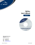
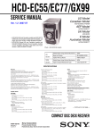
HCD-EC68P/EC78P SERVICE MANUAL US Model HCD-EC68P/EC78P Canadian Model UK Model Ver. 1.0 2008.03 HCD-EC78P Australian Model HCD-EC68P • HCD-EC68P is the amplifier, CD player and tuner section in MHC-EC68Pi. • HCD-EC78P is the amplifier, CD player and tuner section in MHC-EC78Pi. Photo : HCD-EC78P Model Name Using Similar Mechanism Mechanism Type CDM77B-K6BD90-WOD NEW CDM88A-K6BD90-WOD HCD-EC68 Except EC78P (UK) CDM77B-K6BD90-WOD EC78P (UK) CDM88A-K6BD90-WOD Base Unit Name BU-K6BD90-WOD Optical Pick-up Block Name KSM-213DCP SPECIFICATIONS General Inputs Main unit AUDIO POWER SPECIFICATIONS POWER OUTPUT AND TOTAL HARMONIC DISTORTION: (HCD-EC78P The United States model only) Low channel With 8 ohm loads, both channels driven, from 120 – 10,000 Hz; 60 watts per channel minimum RMS power, with no more than 0.7% total harmonic distortion from 250 milliwatts to rated output. High channel With 8 ohm loads, both channels driven, from 2,000 – 13,000 Hz; 60 watts per channel minimum RMS power, with no more than 0.7% total harmonic distortion from 250 milliwatts to rated output. AUDIO POWER SPECIFICATIONS POWER OUTPUT AND TOTAL HARMONIC DISTORTION: (HCD-EC68P The United States model only) With 6 ohm loads, both channels driven, from 120 – 10,000 Hz; 40 watts per channel minimum RMS power, with no more than 0.7% total harmonic distortion from 250 milliwatts to rated output. section HCD-EC78P: US and Canadian models RMS output power (reference): Low channel 95 W + 95 W (per channel at 8 Ω, 1 kHz, 10% THD) High channel 95 W + 95 W (per channel at 8 Ω, 8 kHz, 10% THD) HCD-EC78P: UK model Power output (rated): Low channel 50 W + 50 W (at 8 Ω, 1 kHz, 1% THD) High channel 50 W + 50 W (at 8 Ω, 8 kHz, 1% THD) RMS output power (reference): Low channel 70 W + 70 W (per channel at 8 Ω, 1 kHz, 10% THD) High channel 70 W + 70 W (per channel at 8 Ω, 8 kHz, 10% THD) HCD-EC68P RMS output power (reference): 70 W + 70 W (per channel at 6 Ω, 1 kHz, 10% THD) AUDIO IN (stereo mini jack): Sensitivity 800 mV, impedance 22 kilohms Power requirements: Outputs PHONES (stereo mini jack): Accepts headphones with an impedance of 8 Ω or more SPEAKER: impedance HCD-EC78P: 8 Ω HCD-EC68P: 6 Ω CD player section System: Compact disc and digital audio system Laser: Semiconductor laser (λ=770 – 810 nm) Emission duration: continuous Frequency response: 20 Hz – 20 kHz Signal-to-noise ratio: More than 90 dB Dynamic range: More than 88 dB Sony Corporation Audio Business Group Published by Sony Techno Create Corporation USA model: 210 W Canadian model: 270 VA UK model: 160 W 0.5 W (in Power Saving Mode) 110 W Approx. 200 × 306 × 415 mm Mass (excl. speakers): HCD-EC78P: US and Canadian models Approx. 5.8 kg HCD-EC78P: UK model FM tuner section: Tuning range North American model: 87.5 – 108.0 MHz (100 kHz step) UK and Australian models: 87.5 – 108.0 MHz (50 kHz step) Intermediate frequency: 10.7 MHz 2008C05-1 © 2008.03 HCD-EC78P Dimensions (w/h/d) (excl. speakers): FM stereo, FM/AM superheterodyne tuner Antenna: FM lead antenna AM loop antenna 9-889-053-01 Power consumption: HCD-EC68P Tuner section AM tuner section: Tuning range North American model: 530 – 1,710 kHz (with 10 kHz tuning interval) 531 – 1,710 kHz (with 9 kHz tuning interval) Australian model: 531 – 1,710 kHz (with 9 kHz tuning interval) 530 – 1,710 kHz (with 10 kHz tuning interval) Intermediate frequency: 450 kHz UK model: 531 – 1,602 kHz (with 9 kHz tuning interval) Intermediate frequency: 450 kHz North American model: AC 120 V, 60 Hz Australian model: AC 230 – 240 V, 50/60 Hz UK model: AC 230 V, 50/60 Hz Approx. 6.1 kg HCD-EC68P Approx. 4.7 kg COMPACT DISC RECEIVER HCD-EC68P/EC78P Notes on chip component replacement • Never reuse a disconnected chip component. • Notice that the minus side of a tantalum capacitor may be damaged by heat. Flexible Circuit Board Repairing • Keep the temperature of soldering iron around 270 °C during repairing. • Do not touch the soldering iron on the same conductor of the circuit board (within 3 times). • Be careful not to apply force on the conductor when soldering or unsoldering. CAUTION Use of controls or adjustments or performance of procedures other than those specified herein may result in hazardous radiation exposure. This appliance is classified as a CLASS 1 LASER product. This marking is located on the rear exterior. SAFETY CHECK-OUT After correcting the original service problem, perform the following safety check before releasing the set to the customer: Check the antenna terminals, metal trim, “metallized” knobs, screws, and all other exposed metal parts for AC leakage. Check leakage as described below. LEAKAGE TEST The AC leakage from any exposed metal part to earth ground and from all exposed metal parts to any exposed metal part having a return to chassis, must not exceed 0.5 mA (500 microamperes.). Leakage current can be measured by any one of three methods. 1. A commercial leakage tester, such as the Simpson 229 or RCA WT-540A. Follow the manufacturers’ instructions to use these instruments. 2. A battery-operated AC milliammeter. The Data Precision 245 digital multimeter is suitable for this job. 3. Measuring the voltage drop across a resistor by means of a VOM or battery-operated AC voltmeter. The “limit” indication is 0.75 V, so analog meters must have an accurate low-voltage scale. The Simpson 250 and Sanwa SH-63Trd are examples of a passive VOM that is suitable. Nearly all battery operated digital multimeters that have a 2 V AC range are suitable. (See Fig. A) To Exposed Metal Parts on Set 0.15 μF 1.5 kΩ AC voltmeter (0.75 V) Earth Ground Fig. A. SAFETY-RELATED COMPONET WARNING! COMPONENTS IDENTIFIED BY MARK 0 OR DOTTED LINE WITH MARK 0 ON THE SCHEMATIC DIAGRAMS AND IN THE PARTS LIST ARE CRITICAL TO SAFE OPERATION. REPLACE THESE COMPONENTS WITH SONY PARTS WHOSE PART NUMBERS APPEAR AS SHOWN IN THIS MANUAL OR IN SUPPLEMENTS PUBLISHED BY SONY. ATTENTION AU COMPOSANT AYANT RAPPORT À LA SÉCURITÉ! LES COMPOSANTS IDENTIFIÉS PAR UNE MARQUE 0 SUR LES DIAGRAMMES SCHÉMATIQUES ET LA LISTE DES PIÈCES SONT CRITIQUES POUR LA SÉCURITÉ DE FONCTIONNEMENT. NE REMPLACER CES COM- POSANTS QUE PAR DES PIÈCES SONY DONT LES NUMÉROS SONT DONNÉS DANS CE MANUEL OU DANS LES SUPPLÉMENTS PUBLIÉS PAR SONY. 2 Using an AC voltmeter to check AC leakage. HCD-EC68P/EC78P SECTION 1 SERVICING NOTES TABLE OF CONTENTS 1. SERVICING NOTES ............................................. 3 2. GENERAL .................................................................. 6 3. DISASSEMBLY 3-1. 3-2. 3-3. 3-4. 3-5. 3-6. 3-7. 3-8. 3-9. 3-10. 3-11. 3-12. 3-13. 3-14. Disassembly Flow ........................................................... Side Panel (L)/(R) ........................................................... Panel (Top) ...................................................................... MAIN Board ................................................................... Front Panel Block (EC78P: UK) .................................... Front Panel Block (EC68P/EC78P: US, Canadian)........ Back Panel Block ............................................................ 3 CD Mechanism Block (EC78P: UK) ........................... Base Unit (EC78P: UK) .................................................. 1 CD Mechanism Block (EC68P/EC78P: US, Canadian) ...................................... Base Unit (EC68P/EC78P: US, Canadian) ..................... Belt (EC68P/EC78P: US, Canadian) .............................. Belt (EC78P: UK) ........................................................... OP Base Assy (KSM-213D) ........................................... 4. TEST MODE ............................................................ 18 5. ELECTRICAL ADJUSTMENTS ........................ 22 6. DIAGRAMS 6-1. 6-2. 6-3. 6-4. 6-5. 6-6. 6-7. 6-8. 6-9. 6-10. 6-11. 6-12. 6-13. 6-14. 6-15. 6-16. 6-17. Block Diagram - CD SERVO, TUNER Section -........... Block Diagram - MAIN Section -................................... Printed Wiring Board - CD Board - ................................ Schematic Diagram - CD Board - ................................... Printed Wiring Boards - MAIN Section - ....................... Schematic Diagram - MAIN Section (1/3) - ................... Schematic Diagram - MAIN Section (2/3) - ................... Schematic Diagram - MAIN Section (3/3) - ................... Printed Wiring Board - HI AMP Board (EC78P) - ......... Schematic Diagram - HI AMP Board (EC78P) - ............ Printed Wiring Board - LOW AMP Board - ................... Schematic Diagram - LOW AMP Board - ...................... Printed Wiring Board - PANEL Board - ......................... Schematic Diagram - PANEL Board - ............................ Printed Wiring Boards - KEY Section - .......................... Schematic Diagram - KEY Section - .............................. Printed Wiring Board - MOTOR Board (EC68P/EC78P: US, Canadian models) - ....................... 6-18. Schematic Diagram - MOTOR Board (EC68P/EC78P: US, Canadian models) - ....................... 6-19. Printed Wiring Board - PT Board - ................................. 6-20. Schematic Diagram - PT Board - .................................... 7. 7-1. 7-2. 7-3. 7-4. 7-5. 15 15 16 16 17 25 26 28 29 30 31 32 33 34 34 35 35 36 37 38 38 39 39 40 41 EXPLODED VIEWS Panel Section................................................................... Front Panel Section ......................................................... Chassis Section ............................................................... Main Section ................................................................... 3 CD Mechanism Section (EC78P: UK) (CDM88A-K6BD90-WOD) ........................................... 7-6. 1 CD Mechanism Section (Except EC78P: UK) (CDM77B-K6BD90-WOD) ........................................... 8. 10 11 11 12 12 13 13 14 14 47 48 49 50 NOTES ON HANDLING THE OPTICAL PICK-UP BLOCK OR BASE UNIT The laser diode in the optical pick-up block may suffer electrostatic break-down because of the potential difference generated by the charged electrostatic load, etc. on clothing and the human body. During repair, pay attention to electrostatic break-down and also use the procedure in the printed matter which is included in the repair parts. The flexible board is easily damaged and should be handled with care. NOTES ON LASER DIODE EMISSION CHECK The laser beam on this model is concentrated so as to be focused on the disc reflective surface by the objective lens in the optical pickup block. Therefore, when checking the laser diode emission, observe from more than 30 cm away from the objective lens. UNLEADED SOLDER Boards requiring use of unleaded solder are printed with the leadfree mark (LF) indicating the solder contains no lead. (Caution: Some printed circuit boards may not come printed with the lead free mark due to their particular size) : LEAD FREE MARK Unleaded solder has the following characteristics. • Unleaded solder melts at a temperature about 40 °C higher than ordinary solder. Ordinary soldering irons can be used but the iron tip has to be applied to the solder joint for a slightly longer time. Soldering irons using a temperature regulator should be set to about 350 °C. Caution: The printed pattern (copper foil) may peel away if the heated tip is applied for too long, so be careful! • Strong viscosity Unleaded solder is more viscou-s (sticky, less prone to flow) than ordinary solder so use caution not to let solder bridges occur such as on IC pins, etc. • Usable with ordinary solder It is best to use only unleaded solder but unleaded solder may also be added to ordinary solder. RELEASING THE DISC TRAY LOCK The disc tray lock function for the antitheft of an demonstration disc in the store is equipped. Releasing Procedure: 1. Press [I/1] button to turn the power on. 2. Press the [FUNCTION] button to select CD function. 3. While pressing the [x] button, press the [Z] button for more 5 seconds). 4. The message “UNLOCKED” is displayed and the disc tray is unlocked. Note: When “LOCKED” is displayed, the slot lock is not released by turning power on/off with the [I/1] button. 51 52 ELECTRICAL PARTS LIST .............................. 53 3 HCD-EC68P/EC78P HOW TO OPEN THE TRAY WHEN POWER SWITCH TURN OFF Pull the tray by the hand. (EC78P: UK) lever (EXCEPT EC78P: UK) boss gear Turn a gear by a driver till a lever falls down to the position of the figure. Slide the boss by a driver. HOW TO REMOVE THE KNOB (VOL) knob (VOL) front panel block (back view) hole Push the knob (VOL) by the flat head driver. 4 HCD-EC68P/EC78P CAPACITOR DISCHARGE FOR ELECTRIC SHOCK PREVENTION In checking the MAIN board, make a capacitor discharge of C622 and C626 for electric shock prevention. 800 Ω/2W C626 MAIN board C622 MAIN board 800 Ω/2W MODEL IDENTIFICATION – Back Panel – POWER VOLTAGE INDICATION Model Power Voltage Indication EC68P: US/EC78P: US and Canadian models AC 120 V, 60 Hz EC68P: Australian model AC 230 - 240 V, 50/60 Hz EC78P: UK model AC 230 V, 50/60 Hz 5 HCD-EC68P/EC78P SECTION 2 GENERAL This section is extracted from instruction manual. HCD-EC68P/EC78P: US and Canadian models: Basic Operations Adjusting the sound Listening to the radio To adjust the volume 1 Select “TUNER FM” or “TUNER AM.” Press FUNCTION +/− (or FUNCTION on the unit) repeatedly. Press VOLUME +/− (or turn the VOLUME control on the unit) . 2 Select the tuning mode. To Generate a more dynamic sound (Dynamic Sound Generator X-tra) Press DSGX on the unit. Press TUNING MODE repeatedly until “AUTO” appears. 3 Tune in the desired station. Press +/− (or TUNING +/− on the unit) . Scanning stops automatically when a station is tuned in, and then “TUNED” and “ST” (for stereo programs) appear. EQ . Playing a CD/MP3 disc 2 Place a disc. Press (open/close) on the unit, and place a disc with the label side up on the disc tray. To close the disc tray, press (open/close) on the unit. this may damage the unit. Press (play) . To Pause playback Press (pause) . To resume play, press the button again. Stop playback (stop) . +/− (select folder) . Find a point in a / (go back/go forward) (or / on the unit) . Hold down / (rewind/fast forward) during playback, and release the button at the desired point. Select Repeat Play REPEAT repeatedly until “REP” or “REP1” appears. Before using the system Slide and remove the battery compartment lid , and insert the two R6 (size AA) batteries (supplied), side Press PLAY MODE repeatedly while the player is stopped. You can select normal play (no display or “ * When playing a CD-DA disc, (SHUF) Play performs the same operation as normal (SHUF) Play. Notes on Repeat Play • • it. Notes on playing MP3 discs • • With normal use, the batteries should last for about six months. • batteries. • If you do not use the remote for a long period of time, remove the batteries to avoid damage from battery leakage and corrosion. • Batteries installed devices shall not be exposed to excessive heat such To set the clock • • • • • Press (on/standby) to turn on the system. Press TIMER MENU / repeatedly to (enter) . select “CLOCK,” and then press 3 Set the time. Press / repeatedly to set the hour, then press (enter) Use the same procedure to set the minutes. Note power failure occurs. 6 the disc. “.MP3”. malfunction. − folders is 150 (including the root folder). − − − 1 Turn on the system. 2 Select the clock set mode. If “TUNED” does not appear and the scanning does not stop, press TUNING MODE repeatedly until “MANUAL” appears, and then press +/− (or TUNING +/− on the unit) repeatedly to tune in the desired station. To Change information on the display* Change Display mode (See below.) Press DISPLAY repeatedly when the system is turned on. DISPLAY repeatedly when the * For example, you can view CD/MP3 disc information, such as; − − ”) during normal play. − artist name (“ ”) during normal play. − album or folder name (“ ”) during normal play. − total playing time while the player is stopped. Display mode Power Saving Mode1) to operate. Clock2) 1) You cannot set the clock in Power Saving Mode. 2) To change the play mode (“SHUF” or “ play (“PGM”). Notes on using the remote To tune in a station with a weak signal Changing the display Select a folder on an MP3 disc To use the remote Press (stop) . Press FM MODE repeatedly until “MONO” appears remote, but the same operations can also be performed using the buttons on the unit having the same or similar names. To stop automatic scanning To reduce static noise on a weak FM stereo station 3 Start playback. • device, and recording media cannot be guaranteed. Incompatible MP3 discs may produce noise or interrupted audio or may not play at all. Notes on playing multisession discs • If the disc begins with a CD-DA (or MP3) session, it is recognized as a CD-DA (or MP3) disc, and playback continues until another session is encountered. • A disc with a mixed CD format is recognized as a CD-DA (audio) disc. To connect an optional headphones Connect headphones to the PHONES jack on the unit. To connect an optional component Connect additional audio source components to the AUDIO IN jack on the unit using an analog audio cord (not supplied). Turn down the volume on the system, and then select the AUDIO IN function. To connect a DIGITAL MEDIA PORT adaptor Connect the DIGITAL MEDIA PORT adaptor to the DMPORT on the unit. You need to connect the DIGITAL MEDIA PORT adaptor to an optional audio device (portable audio player, etc.). Notes on DIGITAL MEDIA PORT adaptor 1 Select the CD function. Press FUNCTION +/− (or FUNCTION on the unit) repeatedly. Using optional audio components eight seconds. Notes on the display information • Characters that cannot be displayed appear as “_”. • − total playing time for an MP3 disc. − • − bit rate). − 1, Level 2 or Joliet in the expansion format. • − total playing time for a CD-DA disc during normal play. − remaining playing time for a track. − version 2 tags are used (ID3 version 2 tag information display has priority when both ID3 version 1 and version 2 tags are used for a − up to 15 characters of ID3 tag information using uppercase letters (A to Z), numbers (0 to 9), and symbols (‘< > * + , – / @ [ \ ] _). • Available DIGITAL MEDIA PORT adaptors vary in each area. • Do not connect an adaptor other than the DIGITAL MEDIA PORT adaptor. • Do not connect or disconnect the DIGITAL MEDIA PORT adaptor to/from the DMPORT while the system is on. • When using a DIGITAL MEDIA PORT adaptor that has video output function, connect the adaptor directly to the TV. • For details about the DIGITAL MEDIA PORT adaptor, refer to the operating instructions supplied with your DIGITAL MEDIA PORT adaptor. HCD-EC68P/EC78P Other Operations Using the timers timers, the Sleep Timer has priority. Creating your own CD program (Program Play) Use buttons on the remote to use the timer functions. Sleep Timer: Use buttons on the remote to create your own program. To change the AM tuning interval 1 Make sure the power cord and speaker cords are 10 kHz. Use buttons on the unit to change the AM tuning interval. 2 Find your problem in the checklist below, and take 1 the indicated corrective action. If the issue persists, contact your nearest Sony dealer. system. 2 Press DISPLAY to display the clock. 3 While holding down TUNING + , press . function. the clock is not set. Press SLEEP repeatedly. If you select “AUTO,” the Press PLAY MODE repeatedly until “PGM” appears or in 100 minutes. Immediately unplug the power cord, and check the Play Timer: • Are the + and − speaker cords short-circuited? • Is anything blocking the ventilation holes on the top or back of the system? To improve tuner reception to be all right, reconnect the power cord, and turn on the system. If the issue persists, contact your nearest Sony dealer. 1 Press FUNCTION +/− (or FUNCTION on the unit) 1 Press FUNCTION +/− repeatedly to select the CD 2 Troubleshooting while the player is stopped. 3 Press / repeatedly until the desired track number appears. You can wake up to CD or tuner at a preset time. +/− repeatedly to select the desired folder, and then select Make sure you have set the clock. 1 Prepare the sound source. Press VOLUME +/− to adjust the volume. If “PROTECT” appears on the display your own CD program. 2 Press TIMER MENU . 3 Press / repeatedly to select “PLAY SET,” then press . The system does not turn on. • Is the power cord plugged in? Total playing time of the selected track 4 Set the time to start playback. 4 Press 5 Repeat steps 3 through 5 to program additional Press / repeatedly to set the hour, then press . above to set the minutes. . 6 General tray. To play the same program again, select the CD function, and then press . To cancel Program Play Press PLAY MODE repeatedly until “PGM” disappears while the player is stopped. Press CLEAR while the player is stopped. To view program information, such as total track number of the program 5 Use the same procedure as in step 4 to set the time to stop playback. 6 Select the sound source. Press / repeatedly until the sound source you want appears, and then press shows the timer settings. 7 Press If the system is on at the preset time, the Play Timer will not play. To activate or check the timer again 1 Press TIMER MENU . Press DISPLAY repeatedly. Presetting radio stations You can preset your favorite radio stations and tune them in instantly by selecting the corresponding preset number. 1 Tune in the desired station (See “Listening to the radio”). Preset number • Are the + and − speaker cords short-circuited? • Are you using only the supplied speakers? • Is anything blocking the ventilation holes on the top or back of the system? Sound comes from one channel, or the left and right volumes are unbalanced. • Move the system away from sources of noise. • • cord. The remote does not function. • Remove any obstacles between the remote and the remote sensor on the unit, and position the unit CD/MP3 player The sound skips, or the disc will not play. Tip manually. • Wipe the disc clean, and replace it. • Move the system to a location away from vibration (for example, on top of a stable stand). • Move the speakers away from the system, or place them on separate stands. At high volume, speaker vibration may cause the sound to skip. • Return to Normal Play by pressing PLAY MODE repeatedly until both “PGM” and “SHUF” disappear. 3 Press +/− (or TUNING +/− on the unit) repeatedly to select your desired preset number. If another station is already assigned to the selected preset number, the station is replaced by the new stations. . 4 Press 5 Repeat steps 1 through 4 to store other stations. preset stations are retained for about half a day even if you disconnect the power cord or if a power failure occurs. 6 To call up a preset radio station, press TUNING MODE repeatedly until “PRESET” appears, and then press +/− (or TUNING +/− on the unit) repeatedly to select the desired preset number. CD player power, repeat the procedure until “CD POWER ON” appears. To reset the system to factory settings If the system still does not operate properly, reset the system to factory settings. Use buttons on the unit to reset the unit to its factory default settings. 2 Press , FUNCTION , and at the same Repeat the same procedure as above until “OFF” appears . in step 3, and then press To change the setting to display the clock, and then press while holding down . “CD POWER OFF” appears. With CD player power 1 Disconnect and reconnect the power cord, and then To cancel the timer . repeatedly to select the CD function. 2 Press 3 Severe hum or noise. • Point the remote at the system’s sensor. • Move the remote closer to the system. press management function. By default, CD power is turned on. • Place the speakers as symmetrically as possible. • Connect only the supplied speakers. 2 Press . 3 Press / repeatedly to select “PLAY SEL,” then Start over from step 1. 2 Press TUNER MEMORY . There is no sound. All the AM preset stations are erased. To reset the interval to the factory preset, repeat the procedure. Starting playback takes more time than usual. − a disc recorded with a complicated tree structure. − a disc recorded in multisession mode. − can be added). − a disc that has many folders. turn on the system. time. stations, timer, and the clock, are deleted. Messages CANNOT LOCK : you have done the procedure of “When carrying this system.” COMPLETE : FULL : (steps). LOCKED : nearest Sony dealer. NO DISC : loaded a disc that cannot be played. NO STEP : All of the programmed tracks have been erased. OVER : You have reached the end of the disc while pressing during playback or pause. PUSH STOP : You pressed PLAY MODE during playback. PROTECT : − Speaker cords may be short-circuited. − See “If “PROTECT” appears on the display” to check what to do if this message appears. READING : disc. Some buttons are not available. TIME NG : the same time. The disc tray does not open and “LOCKED” appears. • Contact your Sony dealer or local authorized Sony service facility. Tuner Severe hum or noise, or stations cannot be display.) • Connect the antenna properly. • Find a location and an orientation that provide good reception, and then set up the antenna again. • Keep the antennas away from the speaker cords and the power cord to avoid picking up noise. • 7 HCD-EC68P/EC78P HCD-EC78P: UK model: Basic Operations Adjusting the sound Listening to the radio Using optional audio components To adjust the volume 1 Select “TUNER FM” or “TUNER AM.” To connect an optional headphones Press FUNCTION +/− (or FUNCTION on the unit) repeatedly. Press VOLUME +/− (or turn the VOLUME control on the unit) . 2 Select the tuning mode. To Generate a more dynamic sound (Dynamic Sound Generator X-tra) Press DSGX on the unit. Press TUNING MODE repeatedly until “AUTO” appears. 3 Tune in the desired station. Press +/− (or TUNING +/ on the unit) . Scanning stops automatically when a station is tuned in, and then “TUNED” and “ST” (for stereo programs) appear. EQ . Playing a CD/MP3 disc 2 Place a disc. Press (open/close) on the unit, and place a disc with the label side up on the disc tray. To place shown below. To close the disc tray, press (open/close) on the unit. this may damage the unit. To stop automatic scanning Press (stop) . To tune in a station with a weak signal If “TUNED” does not appear and the scanning does not stop, press TUNING MODE repeatedly until “MANUAL” appears, and then press +/− (or TUNING +/− on the unit) repeatedly to tune in the desired station. To reduce static noise on a weak FM stereo station Press FM MODE repeatedly until “MONO” appears Changing the display 3 Select a disc. If the discs are currently stopped, press DISC SKIP . To change discs while in other functions, press DISC 1 − 3 on the unit. 4 Start playback. Press (play) . To exchange other discs during playback, press EX-CHANGE on the unit. remote, but the same operations can also be performed using the buttons on the unit having the same or similar names. Before using the system To use the remote Slide and remove the battery compartment lid , and insert the two R6 (size AA) batteries (supplied), side To Pause playback Press (pause) . To resume play, press the button again. Stop playback (stop) . Select a folder on an MP3 disc +/− (select folder) . Find a point in a Select Repeat Play REPEAT repeatedly until “REP” or “REP1” appears. To change the play mode Press PLAY MODE repeatedly while the player is stopped. You can select normal play (no display for all discs or “1 DISC” for a disc or “ Notes on using the remote • With normal use, the batteries should last for about six months. • batteries. • If you do not use the remote for a long period of time, remove the batteries to avoid damage from battery leakage and corrosion. • Batteries installed devices shall not be exposed to excessive heat such To set the clock or “ (“PGM”). * When playing a CD-DA disc, (SHUF) Play performs the same operation as 1 DISC (SHUF) Play. Notes on Repeat Play • • • Press (on/standby) to turn on the system. 2 Select the clock set mode. Press TIMER MENU / repeatedly to (enter) . select “CLOCK,” and then press 3 Set the time. Press / repeatedly to set the hour, then press (enter) Use the same procedure to set the minutes. Notes on playing MP3 discs • • • • • • the disc. “.MP3”. malfunction. − folders is 150 (including the root folder). − − − Note power failure occurs. time. it. 1 Turn on the system. • device, and recording media cannot be guaranteed. Incompatible MP3 discs may produce noise or interrupted audio or may not play at all. Notes on playing multisession discs • If the disc begins with a CD-DA (or MP3) session, it is recognized as a CD-DA (or MP3) disc, and playback continues until another session is encountered. • A disc with a mixed CD format is recognized as a CD-DA (audio) disc. 8 To Change information on the display* Change Display mode (See below.) Press DISPLAY repeatedly when the system is turned on. DISPLAY repeatedly when the * For example, you can view CD/MP3 disc information, such as; − − ”) during normal play. − artist name (“ ”) during normal play. − album or folder name (“ ”) during normal play. − total playing time while the player is stopped. Display mode Power Saving Mode1) to operate. Clock2) 1) / (go back/go forward) (or / on the unit) . Hold down / (rewind/fast forward) during playback, and release the button at the desired point. To connect an optional component Connect additional audio source components to the AUDIO IN jack on the unit using an analog audio cord (not supplied). Turn down the volume on the system, and then select the AUDIO IN function. To connect a DIGITAL MEDIA PORT adaptor Connect the DIGITAL MEDIA PORT adaptor to the DMPORT on the unit. You need to connect the DIGITAL MEDIA PORT adaptor to an optional audio device (portable audio player, etc.). Notes on DIGITAL MEDIA PORT adaptor 1 Select the CD function. Press FUNCTION +/− (or FUNCTION on the unit) repeatedly. Connect headphones to the PHONES jack on the unit. You cannot set the clock in Power Saving Mode. 2) eight seconds. Notes on the display information • Characters that cannot be displayed appear as “_”. • − total playing time for an MP3 disc. − • − bit rate). − 1, Level 2 or Joliet in the expansion format. • − total playing time for a CD-DA disc when the play mode is “1 DISC”. − remaining playing time for a track. − version 2 tags are used (ID3 version 2 tag information display has priority when both ID3 version 1 and version 2 tags are used for a − up to 15 characters of ID3 tag information using uppercase letters (A to Z), numbers (0 to 9), and symbols (‘< > * + , – / @ [ \ ] _). • Available DIGITAL MEDIA PORT adaptors vary in each area. • Do not connect an adaptor other than the DIGITAL MEDIA PORT adaptor. • Do not connect or disconnect the DIGITAL MEDIA PORT adaptor to/from the DMPORT while the system is on. • When using a DIGITAL MEDIA PORT adaptor that has video output function, connect the adaptor directly to the TV. • For details about the DIGITAL MEDIA PORT adaptor, refer to the operating instructions supplied with your DIGITAL MEDIA PORT adaptor. HCD-EC68P/EC78P Other Operations Troubleshooting Using the timers timers, the Sleep Timer has priority. Creating your own CD program (Program Play) Use buttons on the remote to use the timer functions. Sleep Timer: To change the AM tuning interval 1 Make sure the power cord and speaker cords are 10 kHz. Use buttons on the unit to change the AM tuning interval. 2 Find your problem in the checklist below, and take 1 the indicated corrective action. If the issue persists, contact your nearest Sony dealer. Use buttons on the remote to create your own program. system. 2 Press DISPLAY to display the clock. 3 While holding down TUNING + , press . 1 Press FUNCTION +/− (or FUNCTION on the unit) the clock is not set. Press SLEEP XK repeatedly. If you select “AUTO,” the 2 Press PLAY MODE repeatedly until “PGM” appears or in 100 minutes. Immediately unplug the power cord, and check the Play Timer: • Are the + and − speaker cords short-circuited? • Is anything blocking the ventilation holes on the top or back of the system? To improve tuner reception to be all right, reconnect the power cord, and turn on the system. If the issue persists, contact your nearest Sony dealer. 1 Press FUNCTION +/− (or FUNCTION on the unit) repeatedly to select the CD function. while the player is stopped. 3 Press DISC SKIP to select a disc. 4 Press / (or / on the unit) repeatedly until the desired track number appears. +/− repeatedly to select the desired folder, and then select You can wake up to CD or tuner at a preset time. Make sure you have set the clock. 1 Prepare the sound source. Press VOLUME +/− (or turn VOLUME on the unit) to adjust the volume. your own CD program. 2 Press TIMER MENU . 3 Press / repeatedly to select “PLAY SET,” then press Total playing time of the selected track . 7 . 4 Set the time to start playback. 5 Press 6 Repeat steps 3 through 5 to program additional tray. To play the same program again, select the CD function, and then press . To cancel Program Play Press PLAY MODE repeatedly until “PGM” disappears while the player is stopped. Press CLEAR while the player is stopped. To view program information, such as total track number of the program Press DISPLAY repeatedly. Press / repeatedly to set the hour, then press . above to set the minutes. • Is the power cord plugged in? There is no sound. • Are the + and − speaker cords short-circuited? • Are you using only the supplied speakers? • Is anything blocking the ventilation holes on the top or back of the system? 7 Press If the system is on at the preset time, the Play Timer will not play. To activate or check the timer again 1 Press TIMER MENU . then press . Repeat the same procedure as above until “OFF” appears . in step 3, and then press Tip • Move the system away from sources of noise. • • cord. The remote does not function. • Remove any obstacles between the remote and the remote sensor on the unit, and position the unit • Point the remote at the system’s sensor. • Move the remote closer to the system. CD/MP3 player The sound skips, or the disc will not play. • Wipe the disc clean, and replace it. • Move the system to a location away from vibration (for example, on top of a stable stand). • Move the speakers away from the system, or place them on separate stands. At high volume, speaker vibration may cause the sound to skip. manually. • Return to Normal Play by pressing PLAY MODE repeatedly until both “PGM” and “SHUF” disappear. 6 To call up a preset radio station, press TUNING MODE repeatedly until “PRESET” appears, and then press +/− (or TUNING +/− on the unit) repeatedly to select the desired preset number. If the system still does not operate properly, reset the system to factory settings. Use buttons on the unit to reset the unit to its factory default settings. 2 Press , FUNCTION , and at the same Start over from step 1. preset stations are retained for about half a day even if you disconnect the power cord or if a power failure occurs. To reset the system to factory settings Severe hum or noise. Preset number 4 Press . 5 Repeat steps 1 through 4 to store other stations. CD player power, repeat the procedure until “CD POWER ON” appears. 1 Disconnect and reconnect the power cord, and then Press / repeatedly until the sound source you want appears, and then press shows the timer settings. To change the setting repeatedly to select your desired preset number. If another station is already assigned to the selected preset number, the station is replaced by the new stations. to display the clock, and then press while holding down . “CD POWER OFF” appears. With CD player power • Place the speakers as symmetrically as possible. • Connect only the supplied speakers. to stop playback. 1 Tune in the desired station (See “Listening to the 3 Press +/− (or TUNING +/− on the unit) repeatedly to select the CD function. 2 Press 3 6 Select the sound source. To cancel the timer radio”). The system does not turn on. management function. By default, CD power is turned on. 5 Use the same procedure as in step 4 to set the time You can preset your favorite radio stations and tune them in instantly by selecting the corresponding preset number. 2 Press TUNER MEMORY . General All the AM preset stations are erased. To reset the interval to the factory preset, repeat the procedure. Sound comes from one channel, or the left and right volumes are unbalanced. 2 Press . 3 Press / repeatedly to select “PLAY SEL,” and Presetting radio stations If “PROTECT” appears on the display Starting playback takes more time than usual. • − a disc recorded with a complicated tree structure. − a disc recorded in multisession mode. − can be added). − a disc that has many folders. turn on the system. time. stations, timer, and the clock, are deleted. Messages CANNOT LOCK : you have done the procedure of “When carrying this system.” COMPLETE : FULL : (steps). LOCKED : nearest Sony dealer. NO DISC : loaded a disc that cannot be played. NO STEP : All of the programmed tracks have been erased. OVER : You have reached the end of the disc while pressing during playback or pause. PUSH STOP : You pressed PLAY MODE during playback. PROTECT : − Speaker cords may be short-circuited. − See “If “PROTECT” appears on the display” to check what to do if this message appears. READING : disc. Some buttons are not available. TIME NG : the same time. The disc tray does not open and “LOCKED” appears. • Contact your Sony dealer or local authorized Sony service facility. Tuner Severe hum or noise, or stations cannot be display.) • Connect the antenna properly. • Find a location and an orientation that provide good reception, and then set up the antenna again. • Keep the antennas away from the speaker cords and the power cord to avoid picking up noise. • 9 HCD-EC68P/EC78P SECTION 3 DISASSEMBLY • This set can be disassembled in the order shown below. 3-1. DISASSEMBLY FLOW SET 3-2. SIDE PANEL (L)/(R) (Page 11) 3-3. PANEL (TOP) (Page 11) 3-5. FRONT PANEL BLOCK (EC78P: UK) (Page 12) 3-4. MAIN BOARD (Page 12) 3-8. 3 CD MECHANISM BLOCK (EC78P: UK) (Page 14) 3-9. BASE UNIT (EC78P: UK) (Page 14) 3-14. OP BASE ASSY (KSM-213D) (Page 17) (EC78P: UK) 10 3-6. FRONT PANEL BLOCK (EC68P/EC78P: US, Canadian) (Page 13) 3-10. 1 CD MECHANISM BLOCK (EC68P/EC78P: US, Canadian) (Page 15) 3-13. BELT (EC78P: UK) (Page 16) 3-11. BASE UNIT (EC68P/EC78P: US, Canadian) (Page 15) 3-12. BELT (EC68P/EC78P: US, Canadian) (Page 16) 3-14. OP BASE ASSY (KSM-213D) (Page 17) (EC68P/EC78P: US, Canadian) 3-7. BACK PANEL BLOCK (Page 13) HCD-EC68P/EC78P Note: Follow the disassembly procedure in the numerical order given. 3-2. SIDE PANEL (L)/(R) two screws (BVTP3 × 10) two screws (BVTP3 × 10) four screws (case3 TP) side panel (L) side panel (R) four screws (case3 TP) 3-3. PANEL (TOP) panel (top) two screws (BVTP3 × 10) two claws two screws (BVTP3 × 10) screw (KTP3 × 10) screw (KTP3 × 10) 11 HCD-EC68P/EC78P 3-4. MAIN BOARD connector (CN151) (EC78P) RH MAIN board flexible flat cable (5 core) (CN603) flexible flat cable (5 core) (CN602) (EC78P) RG two screws (BVTP3 × 6) RE two screws (BVTP3 × 10) (EC78P) connector (CN633) connector (CN601) RT two screws (BVTP3 × 10) RB screw (BVTP3 × 10) flexible flat cable (31 core) (CN803) flexible flat cable (9 core) (CN605) flexible flat cable (11 core) (CN609) connector (CN604) flexible flat cable (21 core) (CN608) 3-5. FRONT PANEL BLOCK (EC78P: UK) flexible flat cable (11 core) (CN609) flexible flat cable (31 core) (CN803) flexible flat cable (13 core) (CN302) front panel block lever flexible flat cable (9 core) (CN605) door (CD) 12 pull the tray by hand. two screws (BVTP3 × 10) gear Turn a gear by a driver till a lever falls down to the position of the figure. HCD-EC68P/EC78P 3-6. FRONT PANEL BLOCK (EC68P/EC78P: US, Canadian) flexible flat cable (11 core) (CN609) flexible flat cable (31 core) (CN803) front panel block boss flexible flat cable (9 core) (CN605) pull the tray by hand. Slide the boss by a driver. two screws (BVTP3 × 10) door (1 CD) flexible flat cable (5 core) (CN001) 3-7. BACK PANEL BLOCK connector (CN601) two screws (BVTP3 × 10) (EC78) connector (power cord) (CN053) screw (BVTP3 × 10) two screws (BVTP3 × 10) four screws (BVTP3 × 10) two screws (BVTP3 × 10) back panel block Cut the clamp. Note: Please do not forget fixation by clamping when you install the power cord. 13 HCD-EC68P/EC78P 3-8. 3 CD MECHANISM BLOCK (EC78P: UK) flexible flat cable (21 core) (MAIN board: CN608/ CD board: CN201) 3 CD mechanism block four screws (BVTP3 × 10) flexible flat cable (13 core) two tapes Note: When installing the CD mechanism section, install two tapes for prevention of noise. cover (DLM3) two screws (BVWH) 3-9. BASE UNIT (EC78P: UK) two screws (PTPWHM2.6) insulator two springs (insulator) two screws (PTPWHM2.6) insulator two springs (insulator) insulator base unit insulator 3 CD mechanism block – Bottom view – 14 HCD-EC68P/EC78P 3-10. 1 CD MECHANISM BLOCK (EC68P/EC78P: US, Canadian) PT block connector (CN053) two screws (BVTP4 × 12) three screws (BVTP3 × 10) flexible flat cable (21 core) (CN201) two screws (BVTP4 × 12) 1 CD mechanism block flexible flat cable (5 core) (CN001) 3-11. BASE UNIT (EC68P/EC78P: US, Canadian) floating screw insulator two floating screws two springs (insulator) two floating screws insulator two springs (insulator) insulator base unit insulator loading (BK) assy – Bottom view – 15 HCD-EC68P/EC78P 3-12. BELT (EC68P/EC78P: US, Canadian) position of belt belt belt claw claw tray (AU) 3-13. BELT (EC78P: UK) position of belt belt cover belt two belts (DLM3A) 16 four screws HCD-EC68P/EC78P 3-14. OP BASE ASSY (KSM-213D) op base assy (KSM-213D) flexible flat cable (16 core) (CN301) CD board Remove four solders. 17 HCD-EC68P/EC78P SECTION 4 TEST MODE COLD RESET CD TRAY LOCK The cold reset clears all data including preset data stored in the memory to initial conditions. Execute this mode when returning the set to the customer. Procedure: 1. In the standby status, press the [I/1] button to turn the power on. 2. Press three buttons of [x], [FUNCTION] and at last [I/1] simultaneously. 3. When “RESET” appears, the set enters standby status. This mode is for the antitheft of CD disc in shop. (not for transport) Procedure: 1. Press the [I/1] button to turn the power on. 2. Press the [FUNCTION] button to select CD function. 3. Insert a disc. 4. While pressing the [x] button, press the [Z] button for more 5 seconds. 5. The message “LOCKED” is displayed and the disc tray is locked. (Even if exiting from this mode, the disc tray is still locked) 6. If press the [Z] button to eject the disc, the message “LOCKED” is displayed and can not eject the disc. 7. To release this lock, while pressing the [x] button, press the [Z] button for 5 seconds again. 8. The message “UNLOCKED” is displayed and the disc tray is unlocked. PANEL TEST MODE Enter The Panel Test Mode Procedure: 1. In the standby status, press the [I/1] button to turn the power on. 2. Press three buttons of [DISPLAY], [x], and [FUNCTION] simultaneously. 3. When the panel test mode is activated, LEDs and segments of the liquid crystal display are all turned on. Version Check Procedure: 1. In the panel test mode (all LEDs and segments of the liquid crystal display are turned on), press the [FUNCTION] button. 2. On the liquid crystal display, date and version are displayed “xxxxxxxx”. For example, “1114V102”. 3. From this status, press the [X] button, and the destination and model name are displayed. For example, “CE2” and “ESLO–”. 4. To release from this mode, press three buttons of [DISPLAY], [x], and [FUNCTION] simultaneously. CD POWER MANAGE This mode is for switch the CD power supply on/off. Even if this state pulls out AC plug, it is held. Procedure: 1. Press the [I/1] button to turn the power on. 2. Press the [FUNCTION] button to select CD function. 3. Press the [I/1] button again to turn the power off (standby). 4. After pressing the [DISPLAY] button, while pressing the [x] button, press the [I/1] button. 5. It turns power on and display “CD POWER”, then display “ON” or “OFF”. CHANGE-OVER THE AM TUNING INTERVAL Key Test Mode Procedure: 1. In the panel test mode (all LEDs and segments of the liquid crystal display are turned on), press the [DISPLAY] button. 2. The message “KEY0 0 0”displayed. Whenever any buttons are pressed and the [VOLUME] dial is turned, the value is changed. 3. To release from this mode, press three buttons of [DISPLAY], [x], and [FUNCTION] simultaneously. CD REPEAT 5 LIMIT CANCEL MODE Number of repeats for CD playback is 5 times when the repeat mode is “REPEAT”. This mode enables CD to repeat playback for limitless times. Procedure: 1. Press the [I/1] button to turn the power on. 2. Press the [FUNCTION] button to select CD function. 3. Press three buttons of [DISPLAY], [x], and [l m – TUNING] simultaneously. 4. It enters the CD repeat 5 limit cancel mode and displays “NO LIMIT” 5. To release this mode, press the [I/1] button to turn the power off. CD SHIP MODE This mode can run the CD sled motor optionally. Use this mode, for instance, when cleaning the optical pick-up. Procedure: 1. Press the [I/1] button to turn the power on. 2. Confirm there is no disc in all trays. 3. Press the [FUNCTION] button to select CD function. 4. Press two buttons of [CD N] and [I/1] simultaneously. 5. Set to the CD ship mode. (chucking on) 6. After blink “STANDBY”, “LOCK” is displayed, disconnect the AC plug. 18 (Except EC78P: UK model) The AM tuning interval can be changed over 9 kHz or 10 kHz. Procedure: 1. Press the [I/1] button to turn the power on. 2. Press the [TUNER/BAND] button to select TUNER (AM) function. 3. Press the [I/1] button again to turn the power off (standby). 4. After pressing the [DISPLAY] button, while pressing the [TUNING + M L] button, press the [I/1] button. 5. It turns power on and display “9k STEP” or “10k STEP”, and thus the tuning interval is changed over. CD SHIP AND COLD RESET Procedure: 1. Press the [I/1] button to turn the power on. 2. Confirm there is no disc in all trays. 3. Press the [FUNCTION] button to select CD function. 4. Press three buttons of [PLAY MODE/TUNING MODE], [l m – TUNING] and [I/1] simultaneously. 5. After blink “STANDBY”, “RESET” is displayed, disconnect the AC plug. COMMON TEST MODE Procedure: 1. Press the [I/1] button to turn the power on. 2. Press three buttons of [PLAY MODE/TUNING MODE], [TUNING + M L], and [DISPLAY] simultaneously. 3. It enters the common test mode and displays “COMMON”. 4. Each time the [VOLUME] dial is turned, “VOL MIN”, “VOL 16”, and “VOL MAX” are displayed. 5. To release from this mode, press three buttons of [PLAY MODE/TUNING MODE], [TUNING + M L], and [DISPLAY] simultaneously. HCD-EC68P/EC78P [CD SERVO TEST MODE] This mode can check the servo system operations of the optical pick-up system (= optical unit + CD board). Note1: Do not enter the [CD SERVO TEST MODE] while any other test mode is in progress. Note2: Do not enter any other test mode while the [CD SERVO TEST MODE] is in progress. CD Servo Test Mode Tree: S Curve Mode (BDT S CU) RAM Read Mode (BDTRAM R) How to Enter the CD Servo Test Mode Procedure: 1. Press the [I/1] button to turn the power on. 2. Press the [FUNCTION] button to select CD function. 3. Press three buttons of [CD N], [l m – TUNING] and [DISPLAY] simultaneously. 4. It enters the CD servo test mode and displays “BDT S CU”. How to Exit from the CD Servo Test Mode Procedure: 1. Press three buttons of [CD N], [l m – TUNING] and [DISPLAY] simultaneously. 2. It releases from the CD Servo Test Mode and returns to the ordinary CD function. Key Operation: [ +], [ –]: Use these keys to move between the five modes contained in the CD Servo Test Mode, that are the S-Curve Mode, the RAM Read Mode, the RAM Write Mode, the Command Out Mode and the Error Rate Mode as described below. Also, use these keys to move between the menus within the respective five modes. When [ +] is pressed, the screen advances to the next menu or to the next mode. When [ –] is pressed, the screen returns back to the previous menu or to the previous mode. Use these keys also to increase or decrease the numeric value when changing the numeric value. Pressing [ +] increases the value and pressing [ –] decreases the value. RAM Write Mode (BDTRAM W) Command Out Mode (BDT COMO) [DSGX] , [EQ]: Use these keys to move between the different layers of the hierarchy of the CD Servo Test Mode shown below. Press [DSGX] to move down to the lower layer, and press [EQ] to move up to the higher layer. [TUNING + M L], [l m – TUNING]: Use these keys to move the cursor to the right digit or to the left digit in the six-digit number, when changing the numeric value. Press [TUNING + M L] to move the cursor to the right, and press [l m – TUNING] to return the cursor to the left. Error Rate Mode (BDT ERR) Higher layer LD ON (LD ON) Disc Type (DISCTYPE) Gain Index (GAININDX) RFO GAIN (RFO_GAIN) FEO GAIN (FEO_GAIN) SBAD GAIN (SBAD_GAI) TEO GAIN (TEO_GAIN) Disc Size (DISCSIZE) Op ABRAKE Error (OPABRKER) SBBT Data (SBBT DAT) FEOOCD (FEOOCD) SPG Mask (00 SPG) Fix RF Gain (00 FIX) TMAX ON (00 TMA) Driver Mute OFF (00 D_M) COMOUT6X (COMOUT6X) READ2X (READ2X) REG READ (REG_READ) FEBC? (FEBC?) FGADD? (FGADD?) TEBC? (TEBC?) TGADD? (TGADD?) RFGC? (RFGC?) FEOF? (FEOF?) TEOF? (TEOF?) TEIOCD1? (TEIOCD1?) TEIOCD2? (TEIOCD2?) TEIOCD3? (TEIOCD3?) TEOOCD? (TEOOCD?) FEOOCD? (FEOOCD?) MONITOR (MONITOR) Lower layer of menu hierarchy value indication (AL: 0000, RW: 0001) value indication (0001) value indication (0009) value indication (0005) value indication (0007) value indication (000A) value indication (0000: Non disc, 0001: 8cm, 0002: 12cm) value indication (0000) value indication (006C) value indication (0440) value edit (Non mask:00, Mask:01) value edit (Non Fix:00, AL Fix:01, RW Fix:02) value edit value edit (Normal:00, Forced OFF:01) value edit command out (000000) (OK) value edit command out (60) (50) value edit command out (00) (0000) command out (00) command out (10) command out (00) command out (00) command out (00) command out (FFC0) command out (FFC0) command out (FE80) command out (FF40) command out (FFC0) command out (FD00) command out (F780) value edit command out (570A00) (OK) Error rate indication (00000000) [FUNCTION]: Use this key to execute Command Out in the Command Out Mode. 19 HCD-EC68P/EC78P CD SERVICE MODE This mode can move the SLED of the optical pick-up, and also can turn the optical pick-up laser power on and off. Procedure: 1. Press the [I/1] button to turn the power on. 2. Press three buttons of [CD N], [TUNING + M L], and DISPLAY simultaneously. 3. Press the [FUNCTION] button to select CD function. 4. It enters the CD service mode and displays “SERVICE”. 5. To exit from this mode, press three buttons of [CD N], [TUNING + M L] and DISPLAY simultaneously. Key Operation: [TUNING + M L], [l m – TUNING]: Use these keys to move the SLED. When [TUNING + M L] is pressed in this mode, the SLED moves to outer circumference and the message “SLED OUT” is displayed. When [l m – TUNING] is pressed in this mode, the SLED moves to inner circumference and the message “SLED IN” is displayed. [DISPLAY]: Use this key to turn the optical pick-up laser power on and off. When the laser power is turned on, the message “LD ON” is displayed. When the laser power is turned off, the message “LD OFF” is displayed. CD ERROR CODE The past errors of the CD mechanism (CDM) are displayed as the CDM Errors, and those of the optical pick-up system (= optical unit + CD board) are displayed as the BD Errors as shown below. Procedure: 1. Press the [I/1] button to turn the power on. 2. Press the [FUNCTION] button to select CD function. 3. Press three buttons of [TUNING + M L], [x] and [DISPLAY] simultaneously. 4. Then, the CDM error code is displayed as “M0xxxxxx” (x means hexadecimal number) on the liquid crystal display as shown below. 5. Every pressing of the [TUNING + M L] button in this mode increments the number after “M” starting from “M0” up to “M9”, and then returns to “M0”. Every pressing of the [l m – TUNING] button in this mode decrements the number after “M”. The smaller the error code number is, the newer the error content is. 6. When the [PLAY MODE/TUNING MODE] button is pressed then, the BD error code is displayed as “D0xxxxxx” (x means hexadecimal number) on the liquid crystal display as shown below. In the same way as the CDM error code, use of the [TUNING + M L] and the [l m – TUNING] buttons in this mode enables tracing of the error history. 7. To release from this mode, press the [I/1] button to turn the power off. 20 Contents of “CDM Errors” Error display example M 0 FF 11 42 1 2 3 4 1 It indicates the error history number 0 to 9: The error code number 0 indicates the newest error. 2 It indicates whether the CDM error occurs in the normal operations or during the initialization operation. FF : The error has occurred in the normal operations. Other than FF : The error has occurred during the initialization operation. 3 It indicates the processing during which the trouble has occurred. 01: The disc EJECT processing is in progress. 02: The disc INSERTION-WAITING processing is in progress. 03: Processing of the disc INSERTION-REQUEST for the upper CD tray is in progress. 04: Processing of the disc EJECTION-REQUEST for the upper CD tray is in progress. 05: The disc pulling-in operation is in progress. 06: The disc chucking processing is in progress. 07: The disc re-chucking processing is in progress. 08: The disc chucking-release completion operation is in progress. 4 It indicates the operation during which the trouble has occurred. 00 : Waiting for the operation. 10 to 13 : The disc EJECT operation is in progress. 20 : The disc pulling-in operation is in progress. 30 : The disc chucking-release operation is in progress. 40 to 43 : The disc EJECT operation due to error is in progress. Contents of “BD Errors” Error display example D 0 02 09 01 1 2 3 4 1 It indicates the error history number 0 to 9: The error code number 0 indicates the newest error. 2 It indicates the error content 01: The focus servo cannot lock-in. 02: GFS is no good (NG). 03: The startup time exceeds the specified period of time (time over) 04: The focus servo is unlocked continuously. 05: Q code cannot be obtained within the specified period of time. 06: The tracking servo cannot lock-in. 07: Blank disc HCD-EC68P/EC78P 3 It indicates the on-going processing of optical pick-up system (= optical unit + BD board) when the trouble has occurred. 01: The CD SHIP mode processing is in progress. 02: The POWER OFF processing is in progress. 03: The INITIALIZE processing is in progress. 04: The optical pick-up system (= optical unit + BD board) is in the stop state. 05: The STOP operation is in progress. 06: The startup processing is in progress. 07: The TOC read-in processing is in progress. 08: The SEARCH operation is in progress. 09: The PLAY operation is in progress. 0A: The PAUSE operation is in progress. 0B: The PLAY – MANUAL SEARCH operation is in progress. 0C: The PAUSE – MANUAL SEARCH operation is in progress. 4 It indicates the operation that is being processed when the trouble has occurred. It indicates the step number of each processing specified by 3. Because the numbers of steps are different in each processing, this number is different in each processing. CD FACTORY MODE Note1: Do not enter the [CD FACTORY MODE] while any other testmode is in progress. Note2: Do not enter any other test mode while the [CD FACTORY MODE] is in progress. Procedure: 1. Press the [I/1] button to turn the power on. 2. Press the [FUNCTION] button to select CD function 3. Press three buttons of [CD N], [FUNCTION], and [DISPLAY] simultaneously. 4. It enters the CD factory mode and displays the following message. Key Operation: [DISPLAY]: The display changes in the following order whenever the button is pressed. (Initial display) fcsAG ** (**: Focus AGC value) trkAG ** (**: Track AGC value) RF-AG ** (**: RF AGC value) [DSGX]: RF gain setting changes whenever the button is pressed. “–”: No gain fixation. “AL”: Fix to the gain for AL disc. “RW”: Fix to the gain for RW disc. [EQ]: Tracking servo setting changes whenever the button is pressed. “ON”: Tracking servo ON. “OFF”: Tracking servo OFF. [FUNCTION]: S character mode setting changes whenever the button is pressed. “ ”: S character mode OFF. “S”: S character mode ON. 5. To release from this mode, press the [I/1] button to turn the power off. –X1ON S character mode setting Tracking servo setting RF gain setting 21 HCD-EC68P/EC78P SECTION 5 ELECTRICAL ADJUSTMENTS TUNER SECTION CD SECTION Note: 1. CD Block is basically constructed to operate without adjustment. 2. Use YEDS-18 disc (3-702-101-01) unless otherwise indicated. 3. Use an oscilloscope with more than 10 MΩ impedance. 4. Clean the object lens by an applicator with neutral detergent when the signal level is low than specified value with the following checks. 5. Check the focus bias check when optical pick-up block is replaced. FOCUS BIAS CHECK [AM] Setting: FUNCTION: AM 60 cm loop antenna A loop antenna B AM RF signal generator level meter 32 Ω oscilloscope (DC range) 30% amplitude modulation by 400 Hz signal Output level: 54 dBuV CD board TP121 (RFI) TP124 (VC) + – Procedure : 1. Connect the oscilloscope to TP121 (RFI) and TP124 (VC) on the CD board. 2. Press the [I/1] button to turn the power ON, and press the [Z] button to open the CD disc tray. 3. Set disc (YEDS-18) on the trey and press the [CD N] button to playback. 4. Confirm that oscilloscope waveform is as shown in the figure below. (eye pattern) A good eye pattern means that the diamond shape (◊) in the center of the waveform can be clearly distinguished. VOLT/DIV: 200 mV TIME/DIV: 500 ns FM RF signal generator 0.01 F TP121 (RFI) IC101 22 JACK board MAIN board PHONES jack (J492) ANTENNA CN801 pin MAIN board ANTENNA CN801 pin level meter 32 Ω + – set MAIN board 75kHz frequency ANTENNA deviation by 1K Hz CN801 pin signal Output level: as low as possible (8dBuV) JACK board PHONES jack (J492) digital voltmeter MAIN board IC801 pin XL (TUNER VT) TP124 (VC) + – set [FM] Setting: FUNCTION: FM level: 1.2 ± 0.3 Vp-p Checking Location: – CD Board (Conductor Side) – 0 dB = 1 μV 100 k Ω • Repeat the procedures in each adjustment several times. HCD-EC68P/EC78P AM FREQUENCY COVERAGE ADJUSTMENT (Except EC78P: UK model) Reading on Digital Adjustment Part Frequency Display Voltmeter L801 530 kHz 1.5 ± 0.1 V Confirmation 1,710 kHz FM AUTO STOP CHECK generator SET 8 ± 0.5 V + 75 Ω AM FREQUENCY COVERAGE ADJUSTMENT (EC78P: UK model) Reading on Digital Adjustment Part Frequency Display Voltmeter L801 531 kHz 1.5 ± 0.1 V Confirmation 1,602 kHz 7.2 ± 0.5 V AM TRACKING ADJUSTMENT (Except EC78P: UK model) Adjust for a maximum reading on level meter L805 * 530 kHz AM TRACKING ADJUSTMENT (EC78P: UK model) Adjust for a maximum reading on level meter L805 108 kHz Carrier Freq : A = 87.5 MHz, B = 98 MHz, C = 108 MHz Deviation : 75 kHz Modulation : 1 kHz ANT input : 35 dBu (EMF) Note: Please use 75 ohm “coaxial cable” to connect SG and the set. You cannot use video cable for checking. Please use SG whose output impedance is 75 ohm. 531 kHz FM FREQUENCY COVERAGE ADJUSTMENT Reading on Digital Adjustment Part Frequency Display Voltmeter L803 87.5 kHz 1.75 ± 0.1 V Confirmation Procedure : 1. Turn the power on. 2. Input the following signal from Signal Generator to FM antenna input directly. 6.2 ± 0.5 V 3. Set to FM tuner function and scan the input FM signal with automatic scanning. 4. Confirm that input Frequency of A, B and C detected and automatic scanning stops. The stop of automatic scanning means “The station signal is received in good condition”. FM TRACKING ADJUSTMENT Adjust for a minimum reading on level meter L804 98 MHz Adjustment Location: MAIN board (See page 24) FM DETECTOR ADJUSTMENT Setting: FUNCTION: FM FM RF signal generator MAIN board ANTENNA CN801 pin set Carrier frequency: 98MHz Modulation: deviation by FM 75 kHz Output level: 60 dBuV MAIN board IC801 pin RT (TUNER OUT L-ch) level meter + – MAIN board MAIN board JW801 (TUNER-GND) ANTENNA CN801 pin 1. Turn the set to 98 MHz. 2. Adjust L802 so that modulation distortion may become the best in the vicinity of the maximum value where the tuner out level becomes –15dBuV or more. 23 HCD-EC68P/EC78P Adjustment Location and Connecting Points: – MAIN Board (Component Side) – L804 AM Tracking Adjustment L801 FM Frequency Coverage Adjustment L802 FM Detector Adjustment L803 FM Frequency Coverage Adjustment L805 AM Tracking Adjustment – MAIN Board (Conductor Side) – 3 1 CN801 ANTENNA 36 IC801 1 IC801 pin XL (TUNER VT) 19 18 IC801 pin RT (TUNER OUT L-ch) 24 JW801 (TUNER-GND) HCD-EC68P/EC78P SECTION 6 DIAGRAMS 6-1. BLOCK DIAGRAM - CD SERVO, TUNER Section CN801 ANTENNA FM/AM BAND-PASS FILTER FL803 3 FM-MIX 3 36 FM RF-IN 8 FM IF-IN FM DET-OUT 23 TUNER-L L-OUT 12 22 MPX-IN R-OUT 13 L805 AM TRACKING A R-CH T801 AM IF 1 CF801 AM-MIX 5 1 AM RF-IN 7 AM IF-IN AM DET-OUT 24 D801 L801 AM FREQUENCY COVERAGE 31 AM-OSC +9V L804 FM TRACKING AM/FM-DET, OSC, MIX, PLL, IF AMP IC801 34 FM RF-OUT L803 FM FREQUENCY COVERAGE XOUT 11 FM-DET FM DETECTOR XIN L802 DI DO CL CE AGC 32 FM-OSC 16 18 17 15 25 19 20 X801 75kHz CD-MP3 PROCESSOR IC101 95 97 94 96 100 98 A B C D E F LD AUTOMATIC POWER CONTROL Q301 FNi1 (A) FPi1 (B) FNi2 (C) FPi2 (D) TNi (E) TPi (F) 91 LDo PD 92 MDi VC 84 VRo FOCUS/TRACKING COIL DRIVE, SLED/SPINDLE MOTOR DRIVE IC401 SP+ SPSL+ SLT+ TF+ F- 2 1 12 11 18 17 26 27 VO1+ VO1VO2VO2+ VO3+ VO3VO4+ VO4- LO 30 RO 27 B 57 33 56 55 39 BUS0 BUS1 BUS2 (SO) BUS3 (SI) BUCK (CLK) XCCE PIO0 SBSY XRST 38 39 40 41 42 43 48 54 37 17 18 19 20 25 26 24 43 27 I/O-CD-BUS0 I/O-CD-BUS1 I/O-CD-BUS2 I/O-CD-BUS3 O-CD-BUCK O-CD-CCE I-REQ O-CD-SBSY O-CD-RST S201 (LIMIT) IN1 3 13 DMo IN2’ 9 12 FMo IO0 (/HSO) 20 IN3’ 20 10 TRo XO 24 IN4’ 24 9 FOo XI 23 MUTE 7 CD-L R-CH O-TU-DI I-TU-DO O-TU-CLK O-TU-CE I-TU-ANSD OPTICAL PICK-UP BLOCK (KSM-213DCP) (EC78P: UK) O-3CD-M1+/O-CDM-M1+ O-3CD-M1-/O-CDM-M1O-3CD-M2+/NC O-3CD-M2-/NC 8 10 11 12 I-3CD-SW1/O-CDM-OPEN I-3CD-SW3/O-CDM-CLOSE I-3CD-SW2/NC I-3CD-CHACK I-3CD-STOCK I-1CD-CLOSE_OPEN/NC 7 5 6 21 22 48 MOTOR DRIVE Q311 - 318 (EC68P/EC