1
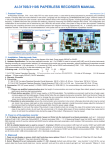
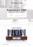
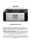
GALAXY 34 VACUUM TUBE STEREO INTEGRATED/POWER AMPLIFIER Thank you for using AUDIO SPACE Galaxy Series vacuum tube stereo integrated /power amplifier. Please read this instruction manual carefully before unpacking the contents and using your amplifier. SPECIFICATIONS n n n Input impedance Output impedance Output power n n n n n n n n n Damping factor Frequency response T.H.D. Total gain Input sensitivity S/N ratio Channel balance Channel separation Vacuum tubes n n n Power requirement Dimension Weight >89k ohm (RCA/Direct In) 4, 8 ohm 16W×2 (TRIODE-CLASS AB PUSH-PULL) 32W×2 (ULTRALINEAR-CLASS AB PUSH-PULL) >5 20Hz∼30kHz -1dB <1% 20Hz∼20kHz (REF. OUTPUT) 25dB 300mV∼600mV >80dB (HUM NOISE<3mV) <1dB 20Hz∼20kHz (MAX. VOLUME) >60dB (1kHz∼3.3kHz) V1, V2, V3, V4: EL34×4 V5, V6: 6N8P (6SN7) ×2 V7, V8: 6N9P (6SL7) ×2 AC∼230V±5% 50/60Hz 330×400×190mm (D×W×H) 22.5kg (N.W.) / 26.2kg (G.W.) * Information and diagrams in this instruction are subject to change without notice. 【 WARNING】 DO NOT OPEN THE CHASSIS OF THIS PRODUCT * * * * To reduce the risk of electric shock, do not remove the bottom cover of amplifier. Do not attempt to repair the product yourself. No user serviceable parts inside. Refer all service to qualified service personnel. Keep liquids away from the amplifier. If liquid is spilled into the unit, disconnect the AC power cord from the unit at once and consult your authorized dealer. 1 CAUTION: BEFORE OPERATING THIS NEW PRODUCT, PLEASE CAREFULLY READ THIS OPERATION MANUAL AND SAVE IT FOR FUTURE REFERENCE. IT MAY BE USEFUL IF YOU HAVE ANY DIFFICULTIES IN OPERATING THIS PRODUCT IN THE FUTURE. IMPORTANT SAFETY INFORMATION 1. It is dangerous to use this new product if It begins to smoke, smell, or make strange noises. If this happens, immediately switch off the power, unplug the power cord and contact the nearest authorized service center. 2. Never remove the bottom cover Do not remove the bottom cover of this product. This product produces high level voltage and current that can be “lethal”. Touching any high voltage parts inside the unit can result in electric shock and/or cause damage to the unit. Do not tamper with any component or part inside the unit. Even with the power turned off, high level of electric charge can remain in the energy storing capacitors for an extended period of time up to months. Any possible adjustment inside the chassis or service required should to be referred to authorized Audio Space Acoustic Laboratory Ltd. dealer or other qualified electronics technician. 3. Avoid exposing this product to direct sunlight, dust, heat or moisture Do not place this product in a location where it is exposed to direct sunlight, heavy dust, intense heat, high humidity, kitchen smoke, etc., as these may cause the product to malfunction. 4. Select a safe and well-ventilated location This product contains vacuum tubes (with glass container) that are fragile and breakable. During operation, the vacuum tubes will generate sufficient heat that can burn to the touch. Therefore, it should be kept away from children and house pets. The unit should be placed in a well ventilated area to allow heat to escape freely. Insufficient air flow may cause the unit to overheat which may result in malfunction or in some cases catch on fire. Always observe the following guidelines: • Keep product at least 10 inches away from all objects such as drapes and wall. • Do not place this product in a confined space or cabinet with poor ventilation. 5. Handling the power Cord Using a damaged power cord or one with bare wires exposed is a fire hazard and may result in electric shock. Always observe the following guidelines: • When unplugging from the AC outlet, never pull on the cord, always grip the plug when unplugging the power cord. • Never place this product itself, furniture, rugs or other heavy objects on the power cord. 2 • • If the power cord must pass near a heater, make sure the cord is far enough from the heater so as to prevent power cord from melting from direct heat or come into contact with the heater accidentally. If the power cord is damaged, replace it before operating the unit again. 6. When the product will not be used for an extended period of time If you go away on holidays or otherwise will be absent for a long period of time, as a safety precaution, unplug the power cord from the electric outlet or switch off the electrical outlet that is connected to the unit via the power cord. 7. Keep the unit away from any moisture Do not place any objects containing water or other liquids near or on this product. If liquid comes into contact with this unit, it can cause malfunction, electrical shock or fire. If liquid should get inside the chassis, unplug the power cord from the AC mains at once and contact the nearest authorized service center or qualified electronics technician. 8. Never insert objects into this product Do not insert or drop any object of metallic, inflammable, or other material into this product through the air vents, as this can cause damage, electrical shock, or possibly fire. 9. Keep the product away from strong magnetic object Operating this product in or near strong magnetic field will affect the performance of this product. 10. Do not alter the intended grounding The product is equipped with THREE WIRE GROUNDING TYPE AC PLUG to provide proper grounding. Altering such grounding may result in electric shock. 3 OPERATING INSTRUCTIONS (I) BEFORE UNPACKING The carton should be placed on a flat surface with the arrows pointing upward. (II) UNPACKING Besides this instruction manual, you will find the following contents: (1) one AUDIO SPACE Galaxy 34 amplifier, (2) a power supply cord, (3) handling gloves and wiping clothe, (4) two pieces of spare fuse, (5) a remote-control unit (batteries supplied). To unpack: 1. remove the top covering foam pad from the carton, 2. carefully lift the amplifier out of the box by holding both sides of the amplifier and transfer it onto a flat surface, 3. remove the plastic bag and protecting paper from the amplifier, 4. remove the vacuum tube protective cage by lifting it straight up, 5. remove all protective padding from the vacuum tubes and make sure the tubes are seated in their sockets properly afterward, 6. remove all protective clear plastic film from the chassis and transformers, 7. replace the vacuum tube protective cage, 8. move the amplifier to where you will connect it to your audio system. NOTE: F If you find any obvious damage to any of the contents, please contact your authorized dealer immediately. F You may want to save the carton and packing material for future use. F Please check whether your line voltage is the same as that marked on this unit. If not, please contact your authorized dealer or our company. (III) CONNECTING Connecting the amplifier to your audio system: • AUDIO INPUT With signal cables (not provided), connect your sound source(s) to the amplifier using the suitable input terminals (CD, AUX1, AUX2) on the rear panel. Do not mix the L and R channel signals between the amplifier and the sound sources. DIR IN – This integrated amplifier can be used as a stereo power amplifier in conjunction with an external pre-amplifier. Using the DIR IN terminals will bypass the VOLUME control circuitry. • SPEAKER OUTPUT With speaker cables (not provided), connect the loudspeakers to the output terminals of the amplifier that have the suitable output impedance on the rear panel of the amplifier. Be sure to match the L and R channels of the amplifier to the L and R loudspeakers. The 0 ohm terminals should be connected to the negative terminal of the loudspeakers while the 4 or 8 ohm terminals should be connected to the positive terminal of the loudspeakers. 4 • POWER Plug the power cord into the power socket on the rear panel and the other end of the cord into an electrical outlet. (IV) POWERING ON When you are sure the connections are correct, turn on the “POWER” switch on the front panel of this amplifier. The “mute” LED will light up indicating the protection delay circuit is triggered and the “VOLUME” is reset to the lowest level automatically. After about 45 seconds, the “mute” LED will go off, indicating the amplifier is in normal powered on mode. The analog meter on the front panel is used to track the output signal level and measure the bias voltage of the output tubes. Turn the “METER RANGE” knob to either “L” or “R” to track the output signal level of the Left or Right channel. (V) REMOTE CONTROL The remote controller can be used to • select the proper input source as indicated by the LEDs on the front panel, • mute or control the volume of the amplifier, • select Triode or Ultralinear mode of operation while the amplifier is on. NOTE: F To prevent damage to circuit, never short-circuit Positive (+) and Negative (-) speaker terminals. F Be sure to set the “VOLUME” control to the lowest position before turning on or disconnecting the speakers while the unit is on. (VI) HEADPHONE JACK The amplifier is optionally equipped with a standard ¼ headphone jack located on the front panel. When a headphone is inserted into the headphone jack, the SPEAKER OUTPUT is automatically switched off. (VII) ADJUSTING BIAS This integrated amplifier is equipped with fixed-bias adjustment. To ensure your amplifier is operating in its intended efficiency, it is necessary to set the bias voltage of the output tubes to specification. In general, adjustment is needed when the system is new or output tubes have been replaced. Once the output tubes have been burned in (about 50 hours of use,) the bias voltage should become very stable. Bias voltage test points and adjustment pots are marked as “+-+” and V1…V4 respectively on the top of the chassis. The proper bias voltage is 0.3V for V1, V2, V3 and V4. Bias voltage can be measured using the analog meter on the front panel. Use the “METER RANGE” knob on the front panel to select the output tube (V1 to V4) for which you are adjusting the bias voltage. With a small flathead screwdriver, turn the corresponding bias adjust pot located on the top of the chassis until the indicator of the meter is pointing at the 5 pre-marked 0.3V point on the lower scale of the meter as shown in the diagram below. Repeat the above procedure for each of the output tubes (V1 to V4). Alternatively, a voltmeter can be used to measure the bias voltage if higher accuracy is desired. Bias voltage is measured across the +/- test point pair closest to the selected output tube as marked on the top of the chassis. In this case the “METER RANGE” knob need not be used. With a small flathead screwdriver, turn the bias pot of the selected output tube (V1, V2, V3, or V4) until the bias voltage is set at 0.3V. Repeat the procedure for each of the output tubes. (VIII) REPLACING VACUUM TUBES Follow the guidelines below if and when it becomes necessary to replace any vacuum tube of the amplifier. Be sure to turn off the power and disconnect the power cord from the amplifier before replacing any vacuum tube. • Front-end & Buffer Stage tubes (6N9P, 6N8P or 6SL7, 6SN7) Any of the tubes can be replaced with tubes of the same type or equivalence. • Output tubes (EL34) The output tubes should be replaced in pairs. The pair on the left and the pair on the right should be matched pairs. A matched quad (all 4 tubes) is highly recommended. Be sure to verify the correct bias voltage afterward. TROUBLESHOOTING Basic troubleshooting of an amplifier is similar to troubleshooting of any other electrical or electronic equipment. Always check the most obvious possible causes first. The table below contains some common problems, causes, and remedies. Problem No power when POWER is turned on Soundstage and image seem to float and not focused No sound Background noise too loud Cause § Power plug not inserted correctly § The fuse is shorted out L and R of input or output are reversed or positive and negative of speaker terminal is reversed § Volume control is set to minimum § Source Selector set to wrong position § Speakers are not connected § Wrong input is selected § Bad signal cable § Signal cable, power supply cord and the video frequency cable are placed too close or get tangled up § Faulty components or 6 Remedy § Plug in securely. § Replace the fuse with a new one of the same type. § Reconnect properly § Turn up the volume § Check Selector § § § § Check speaker cables Check input selection Replace signal cable Re-arrange connections to good order. Keep signal cables away from the others. § Contact authorized dealer. circuits 7 DIAGRAMS DIAGRAM 1 - FRONT PANEL ①MUTE ②CD ③INPUT SEL. ④AUX1 ⑤AUX2 ⑥TR/UL SEL. ⑦DIRECT IN ⑧TR/UL INDICATOR ⑨REMOTE VOLUME ⑩METER HEADPHONE JACK METER SEL. POWER SWITCH DIAGRAM 2 - REAR PANEL ①CD INPUT ②AUX1 INPUT ③AUX2 INPUT ④DIRECT INPUT ⑤REC. OUT ⑥L.CH SPEAKER OUTPUT ⑦R.CH SPEAKER OUTPUT ⑧POWER INPUT SOCKET 8 DIAGRAM 3 - REMOTE CONTROL UNIT ①MUTE ②VOLUME ③INPUT SELECTOR ④TRI/UL SELECTOR DIAGRAM 4 - VACUUM TUBE INSTALLING ①POWER TRANSFORMER ②AUDIO TRANSFORMER ③BIAS ADJ. ④&⑤BIAS TEST TERMINALS * REMARK: V1, V2, V3, V4: EL34 V5, V6: 6N8P V7, V8: 6N9P 9 DIAGRAM 5 - CONNECTIONS 10