1
DUMP N’ GO
MODEL PV 212
SIMPLICITY
8722 E Research Center Rd.
New Hope, MN 55128
Ph: 763-535-4038
Fax: 763-535-4633
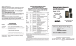
PV 212 shown on Simplicity Champion
Fits models: Champion
____________________________________________________________
SAFETY
Congratulations on purchase of your Protero PV 212 Dump N Go grass catcher!
You will stay on your tractor seat and enjoy a beautiful lawn for a long time to come.
Please read and be familiar with the operator’s manuals that came with your mower and grass catcher. These
manuals provide information for the safest and most effective use of your equipment. If you do not have
operator’s manuals for your mower and for your collection system, please contact your dealer to obtain them.
The Dump N Go catcher simply replaces the bag-type catcher in your collection system; so all safety guidelines
in your operator’s manual for the collection system apply to your Dump N Go as well. Do not operate, nor
allow others to operate your Dump N Go catcher without thorough review and training of these important safety
guidelines.
For your convenience, here are some basic safety guidelines that your operator’s manuals will cover:
Before you operate your material collection system:
•
•
•
•
•
•
•
•
•
Understand the machine safety labels, and pay attention to the symbols for DANGER, WARNING, and
CAUTION.
WARNING: Objects may be thrown from mower.
Do not open catcher while blades are turning.
Shut off engine if getting off mower to inspect catcher.
Operate mower with complete bagging attachment in place
If necessary, use proper front counterweight. Remove counterweight when the material collection
system is removed.
Hopper extends beyond vehicle. Be aware of surrounding objects when making short turns.
Do not operate material collection system unless entire grass catcher is fastened in place with the hopper
cover securely latched.
Do not let anyone ride on the mower or material collection system. Riders are subject to injury such as
being struck by foreign objects or being thrown off. Riders may obstruct the operator’s view and cause
a collision.
Before you inspect catcher or unplug chute:
•
•
•
Stop mower.
Disengage mower PTO.
Stop engine.
Before you back up:
•
•
Stop machine.
Look behind hopper for children or pets.
•
•
•
•
•
•
Dump catcher when half full.
Do not operate on steep slopes.
Before you turn, slow down.
Avoid holes, rocks, and roots.
Mow up and down - not across slopes.
Do not park mower with material collection system on slopes.
Operate safely on slopes:
1
Parking Safely:
•
•
•
•
•
•
Stop machine on a level surface, not a slope.
Disengage PTO.
Wear close fitting clothing and safety equipment appropriate for the job.
Always wear safety goggles or safety glasses with side shields when operating the machine.
Wear a suitable protective device such as earplugs. Loud noise can cause impairment or loss of hearing.
Do not wear radio or music headphones. Safe service and operation requires your full attention.
Practice Safe Maintenance:
•
•
•
•
Understand service procedures before doing work. Keep area clean and dry.
Never service or adjust any part of the collection system while the mower is moving. Keep safety
devices in place and in working condition. Keep hardware tight.
Keep all parts in good condition and properly installed. Fix damage immediately. Replace worn or
broken parts. Remove any buildup of debris.
Unauthorized modifications to the collection system may impair its function and safety. Do not tamper
with its original design.
2
INCLUDED PARTS AND HARDWARE:
TOOLS NEEDED:
•
•
•
•
•
Phillips head screwdriver
Two, 7/16” wrenches (7/16” socket and ratchet suggested)
Two, 9/16” wrenches (9/16” sockets and ratchets suggested)
15/16” wrench (15/16” sockets and ratchets suggested)
Pliers
PARTS:
ITEM #
1
2
3
4
5
6
7
8
9
10
11
12
PART #
212110
212118
212140
212150
212155
212156
212160
212171
212172
212175
212349
212424
DESCRIPTION
212 HOOD ASSEMBLY
212 HINGE BRACKET
CATCHER HINGE ASSEMBLY
PV 212 CATCHER BODY ASSEMBLY
DUMP LEVER ASSEMBLY
DUMP LEVER HANDLE
DOOR ASSEMBLY
HINGE ROD RIGHT
HINGE ROD LEFT
3/8” BALL JOINT ROD END
CHAMPION REAR PLATE
STRAIGHT CHANNEL MOUNT
QUANTITY
1
1
1
1
1
1
1
1
1
2
1
1
3
HARDWARE INCLUDED:
ITEM #
1
2
3
4
5
6
7
8
9
10
11
12
13
PART #
BOLT HH 38 212
BOLT HH 38 2
BOLT HH 38 1
BOLT HH 14 114
BOLT PT 14 212
U-bolt 38 2 Round
FLANGE NUT 38
NUT NYL 38
NUT NYL 14
WASHER 38
BP 233
COTP 125 1
BNTP 375 725
DESCRIPTION
3/8” x 2 ½” HEX HEAD BOLT
3/8” x 2” HEX HEAD BOLT
3/8” x 1” HEX HEAD BOLT
1/4” x 1 ¼” HEX HEAD BOLT
1/4” x 1 ¼” PHILLIPS TRUSS HEAD BOLT
3/8” x 2” ROUND U-BOLT
3/8” SERRATED FLANGE NUT
3/8” NYLOCK NUT
1/4” NYLOCK NUT
3/8” WASHER
BRIDGE PIN 0.930” x 1 1/8” ZINC
COTTER PIN 1/8” x 1” ZINC
BENT PIN 3/8” x 7 ¼” EFF HOLE ZINC
QUANTITY
2
4
18
1
4
4
16
8
5
20
1
2
1
4
ASSEMBLY:
STEP 1:
•
•
Pictured on left: Rear section of Simplicity Champion Mower.
Pictured on right: Champion Rear Plate with holes to be used for mounting.
(A) Champion Rear Plate
(1) 3/8” x 2” round U-bolts (x4)
(2) 3/8" serrated flange nuts (x8)
•
•
•
•
The top rung and bottom rung will be used in mounting the Champion Rear Plate.
Place the Rear Plate against the rungs on the back of the mower.
Place the U-bolts around the rungs and through the holes of the Rear Plate.
Fasten the U-bolts with 3/8” serrated flange nuts.
5
STEP 2:
(A)
(B)
(1)
(2)
(3)
(4)
(5)
Catcher Hinge Assembly
212 Hinge Bracket
3/8” x 2” hex head bolt (x4)
3/8” washer (x4)
3/8” nylock nut (x4)
3/8” x 1” hex head bolt (x2)
3/8” serrated flange nut (x2)
Position the slotted holes of the
Catcher Hinge Assembly to the holes
on the PV212 Catcher Body sides.
•
Insert the 3/8” x 2” bolts through the
Catcher Hinge Assembly and Catcher
Body.
•
Place 3/8” washers on the bolts, from
inside of the Catcher Body.
•
Fasten bolts with 3/8” nylock nuts.
Slide the 212 Hinge Bracket behind the plate attached to the frame of the Catcher body.
Use the 3rd set of holes from the left and insert the 3/8” x 1” bolts through the holes.
Reach behind the plate and Hinge Bracket and thread the 3/8” serrated flange nuts to the bolts and
tighten.
•
•
•
•
6
STEP 3:
(A)
(B)
(1)
(2)
Dump Lever Assembly
Dump Lever Handle
1/4" x 1 ¼” hex head bolt
1/4" nylock nut
•
•
•
•
Insert the Dump Lever Handle into the Dump Lever Assembly
There are 3 holes for spacing the handle to clear the fender of the mower (correctly spacing the
handle may wait until the Catcher is fully mounted to mower).
Insert bolt through holes of the Dump Lever Assembly and Handle.
Fasten bolt with nut.
7
STEP 4:
(A)
(1)
(2)
(3)
(4)
212 Channel Mount
1/4" x 2 ½” phillips truss head bolt (x4)
1/4" nylock nuts (x4)
3/8” x 1” hex head bolt (x4)
3/8” serrated flange nuts (x4)
•
•
•
•
•
Position the Dump Lever Assembly to
the frame of the Catcher Body lining up
the holes.
From the inside of the Catcher, insert the
Phillips trust head bolts through the
holes and fasten with 1/4" nuts.
Place the Channel Mount against the
plate attached to the Catcher frame.
Align the left holes of the Channel
mount to the 6th set (from the left) of holes on the plate.
Insert 3/8” bolts through the Channel Mount and plate.
Reach behind the plate and thread 3/8” serrated flange nuts to the bolts and tighten the bolts.
8
STEP 5:
* Catcher Body removed from view.
•
Lift up the current Catcher Body assembly and insert the Channel Mount into the Champion Rear
Plate (Channel Mount opening should face inwards toward mower).
9
STEP 6:
(1)
(2)
(3)
•
•
•
•
3/8” x 1” hex head bolt (x2)
Hinges (on Door Assembly &
Catcher hinge assembly)
3/8” nylock nut (x2)
Line up the hinges on Door Assembly with
the hinges on the Catcher Hinge Assembly.
Keep the hinges on the Door Assembly to
the right of the hinges on the Catcher Hinge
Assembly.
Through each set of hinges insert 3/8” bolts.
Fasten the bolts with 3/8” nuts.
10
STEP 7:
(1)
(2)
(3)
Hood hinges go in between the Top
Catcher Supports
3/8” x 7 ¼” bent pin
Bridge pin 233
•
•
•
Position the Hood Assembly on top of
the Catcher Body.
Insert the 7 ¼” long bent pin thru the
top holes of the Top Catcher Supports
and thru the holes of the Hood hinges.
Secure pin with Bridge pin 233.
11
STEP 8:
(1)
(2)
(3)
Hinge Rod – Right, Hinge Rod – Left (not shown in close up view)
3/8” washers (x4, 2 for each side of the Dump Lever Assembly)
1/8” Cotter Pin, 1” long (x2, 1 for each side of the Dump Lever Assembly)
•
•
•
•
On the left side of the Dump Lever Assembly (relative to picture above), insert Hinge
Rod – Right thru a 3/8” washer and the hole shown in the Dump Lever Assembly.
Place another washer over the end of the Hinge Rod coming thru the hole. Fasten the Hinge Rod
in place with a Cotter Pin.
Use pliers to bend the ends of the cotter pin out, and around the end of the Hinge Rod.
Repeat the above instructions for the opposite side of the Dump Lever Assembly
12
STEP 9:
(1)
3/8” x 2 ½” hex head bolt (x2, 1 for each side of door
assembly)
3/8” washers (x4, 1 for each side of door assembly)
Rod End (x2, 1 for each side of door assembly)
3/8” nylock nut (x2, 1 for each side of door assembly)
(2)
(3)
(4)
•
•
•
•
•
Screw rod end onto the straight end of the hinge rod. Does
not necessarily need to be tight. Adjustments may be
required.
Insert a 3/8” bolt, thru a 3/8” washer from inside the
catcher door.
Place a washer and rod end on the outside of the door over
the hole and insert the bolt thru the holes.
Fasten with a 3/8” nylock nut.
Repeat the instructions above for the opposite side of the
catcher door.
NOTE: Extra washers are provided to space the rod ends further
from the door if necessary.
Rod ends may need adjustment by either screwing or unscrewing to
change the overall length of the rod. This is required for good
closure of the catcher door and to ensure a proper seal.
Dump lever handle may need to be bent out slightly, to clear mower fender when operating the dump lever.
13
STEP 10:
•
Attach the intake/chute from the mower deck into the intake seal on the Hood of the Catcher.
If provided intake hose is difficult to install onto blower, use soapy water to help lubricate the hose for
easier installation.
LIMITED WARRANTY
We warrant each new Dump N Go catcher to be free from manufacturing defects in normal
service for a period of 12 months from the purchase date.
Our obligation under this warranty is expressly limited, at our option, to the replacement or
repair at PROTERO Inc. (New Hope, MN), or at a service facility designated by us, of such part
or parts as inspected shall disclose to have been defective. This warranty does not apply to
defects caused by improper installation, damage, or unreasonable use (including failure to
provide reasonable and necessary maintenance).
All warranty claims must be pre-approved. We shall not be liable for any claims or fees not
pre-approved. Replacement parts will be sent no charge via UPS Ground. Expedited shipping
services are available for an additional fee.
This warranty is void should the product be repaired or modified in any way not authorized by
PROTERO Inc.
14