1
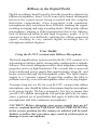
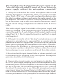
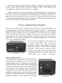
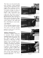
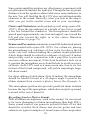
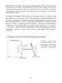
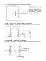
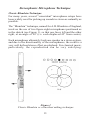
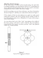
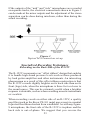
ROYER Labs
Model R-122V
Vacuum Tube Ribbon
Velocity Microphone
Operation Instructions
Manual & User Guide
Made in U.S.A.
TABLE OF CONTENTS
Model R-122V Vacuum Tube Ribbon Microphone
Revised August 2006
Introduction
Active Ribbon Technology
Description
Applications
Ribbons in the Digital World
User Guide
Power Supply Input Module
Operation
Amplification Considerations
Equalization & Ribbon Microphones
Hum, Noise & Mic Orientation
The Sweet Spot
Other Types of Microphones
Proximity Effect & Working Distance
Microphone Technique
Recording Loud or Plosive Sounds
Stereophonic Microphone Technique
Specialized Recording Techniques
Care & Maintenance
Troubleshooting
Features & Specifications
Electrical Specifications
Mechanical Specifications
Polar Pattern & Frequency Response
Notes
Warranty
page 2
page 3
page 5
page 5
page 6
page 6
page 8
page 10
page 11
page 12
page 13
page 14
page 15
page 15
page 17
page 18
page 21
page 23
page 24
page 27
page 28
page 28
page 29
page 30
page 31
page 32
Introduction
R-122V Vacuum Tube Ribbon Microphone
Congratulations on your purchase of a Royer model R-122V
vacuum tube ribbon microphone. The R-122V is a handcrafted
precision instrument capable of delivering superior sound quality
and exceptional performance. The R-122V represents a new level
of performance for ribbon microphones, combining sophisticated
technological advancements with old-world craftsmanship. The
R-122V incorporates a vacuum tube head amplification system
that operates in conjunction with a dedicated AC operated power
supply. This enables the R-122V to deliver the same sensitivity
and output performance that the recording industry has grown
accustomed to with modern condenser microphones. In addition,
the active circuitry completely isolates the ribbon element from
impedance mismatches, short-circuits and other anomalies that
can degrade microphone performance or damage the ribbon. The
R-122V is the first professional grade ribbon microphone that
utilizes vacuum tube electronics and Royer’s patented Offset
Ribbon transducer assembly.
This operator’s manual describes the R-122V, its function and
method of use. It also describes the care and maintenance required
to ensure proper operation and long service life. The User Guide
section of this manual offers practical information that is designed
to maximize the performance capabilities of your microphone.
Royer Labs products are manufactured to the highest industrial
standards using only the finest materials obtainable. Your model
R-122V went through extensive quality control checks before
leaving the factory. Normal care is all that is required to assure
a lifetime of trouble-free service.
Please read this manual thoroughly in order to become familiar
with all of the R-122V’s capabilities. It will assist you in making
the most of your microphone’s superior acoustic properties. This
operator’s manual is a handy reference guide and we suggest you
refer to it whenever questions arise about the use and care of your
R-122V active ribbon microphone.
2
Active Ribbon Technology
Royer Labs pioneered the first active ribbon microphones with
the introduction of the R-122 in 2002. The R-122 is a solid-state
microphone that operates from standard 48-volt simplex power.
The development of that microphone was the result of several
years of effort that actually began with our developing several
vacuum tube versions first. The tube circuitry research was crucial
to the development of the specialized audio transformer used in
the R-122, and a necessary step for the development of our solidstate, phantom powered ribbon microphones. Technically speaking,
Royer vacuum tube ribbon microphones predate our phantom
powdered models, which are now industry standards.
The heart of the R-122V (and all Royer Active Series microphones)
is a proprietary system consisting of a specially designed toroidal
transformer and electronic buffering stage. These work together
as a single unit to provide excellent frequency response, very low
noise, very low distortion and very high SPL handling without
the use of pads. The system gives the R-122V an output level
comparable to that of condenser microphones, and its buffer stage
provides a low impedance output while presenting a perfect
impedance load to the ribbon element. Non-powered ribbon
microphones suffer substantially degraded frequency response
and lowered sensitivity when they are paired to a preamp with
too low of an input impedance. With the R-122V’s vacuum tube
circuitry, the microphone’s frequency response and output are
much less affected by variations in the input impedance of the
following preamp.
Sonically, the R-122V differs from the non-powered R-121 and
the phantom powered R-122 in a few subtle, but significant, ways.
Due to the extra iron in the R-122V’s much larger transformer,
low-end frequencies sound slightly tighter and more focused than
with the R-121 (the R-122 also utilizes this special Royer designed
transformer). Compared with that of the R-121, the transient
response of the R-122 and R-122V is faster, giving the sense of
a more open high-end response.
Sonically, the R-122V is set apart by its increased midrange reach
3
and detail, and a lushness that is hard to describe. The R-122V
also has an enormous amount of headroom available, making it
useful on extremely loud applications. Phantom powered
microphones are limited with regard to maximum headroom as
a result of the phantom power source. With the vacuum tube
design, greater headroom is achievable because the voltage source
is supplied by a dedicated power supply. The vacuum tube operates
with a supply voltage greater than twice that of a phantom powered
microphone. The vacuum tube also provides the extremely high
input impedance required for the specialized ribbon matching
transformer and offers transient response superior to any solidstate component.
Key points:
• No longer is it necessary to mate a ribbon microphone to an
ultrahigh gain, low noise preamplifier for optimum performance.
Any preamplifier of nominal gain will provide good results with
the R-122V.
• No longer is it necessary to carefully consider impedance
matching characteristics when choosing a preamplifier. Microphone
loading is a non-issue (although we still suggest that the load is
above 2,000-ohms for optimum technical performance).
• No longer is it necessary to be concerned about damaging the
ribbon element with phantom power. The vacuum tube electronics
completely isolate the ribbon element.
• No longer is it necessary to worry about the effects of long cable
runs degrading the performance of your ribbon microphone. The
vacuum tube electronics provide a robust low impedance signal
that can handle long cable lengths without loss of signal.
4
Description
The R-122V is a compact, active, bi-directional (figure-eight)
velocity type tube ribbon microphone designed for professional
applications. The figure-eight pickup pattern allows the R-122V
to be addressed from either side with equal sensitivity. The inphase signal is achieved when the microphone is addressed from
the front, indicated by the “ROYER” logo.
The R-122V is reasonably tolerant of shock and vibration, and
performance is unaffected by changes in temperature or humidity.
However, ribbon microphones are somewhat more sensitive to
direct blasts of air and the R-122V is no exception to this rule.
Discretionary use of a windscreen or pop screen, such as the
Royer PS-101, WS58 or equivalent, is highly recommended for
close-miking vocalists or certain types of percussion and wind
instruments.
Applications
The Royer Labs model R-122V is a versatile microphone and is
ideally suited for many critical recording applications. Its smooth
frequency response characteristics and ability to capture detail
make it a fine choice for many instruments, as well as for general
broadcast applications. Its gentle low-frequency proximity effect
makes it especially useful for vocalists and announcers. Female
vocalists often benefit from the R-122V’s ability to capture high
frequencies without distortion or edginess. Orchestral instruments
are captured in a natural-sounding way, free from microphoneinduced “hype.” The R-122V has exceptionally smooth high
frequency characteristics and is devoid of microphone induced
ringing. Phase-related distortion and irregular frequency peaks
are conspicuously absent. These features make the R-122V
vacuum tube ribbon microphone an ideal choice for strings,
woodwinds, percussion and amplified instruments. Theater organs
and electric guitar amplifiers sound big and fat, without unnatural
coloration, when recorded with the R-122V. Acoustic pianos can
be captured accurately without the comb-filtering effects associated
with condenser microphones.
5
Ribbons in the Digital World
Digital recordings benefit greatly from the properties inherent in
ribbon microphones. Since A to D converters cannot distinguish
between the sound source being recorded and the complex
distortion components often associated with condenser
microphones, they sometimes have difficulty tracking the signal,
resulting in ringing and edgy-sounding tracks. With quality ribbon
microphones, ringing is almost nonexistent due to the ribbon’s
lack of distortion artifacts and high frequency peaks. A to D
converters have less difficulty tracking the ribbon-generated
signal, resulting in very smooth digital recordings free of
microphone-related edginess.
User Guide
Using the R-122V vacuum tube Ribbon Microphone
The head amplification system used in the R-122V consists of a
sub-miniature military grade vacuum tube configured as a cathode
follower. This circuit arrangement offers ideal impedance matching
properties and very high headroom. The vacuum tube is powered
from a dedicated power supply that supplies high voltage B+ and
heater current through the microphone cable. The tube's heater
supply is a "constant current" design that enables the tube to
perform correctly, even with microphone cables of varying lengths.
To ensure long service life for your R-122V vacuum tube ribbon
microphone, care should be taken when connecting the microphone
to its power supply. We have prepared a few tips to ensure that
your R-122V ribbon microphone will perform perfectly for many
years; a general set of good habits that apply to both tube ribbon
microphones and tube condenser microphones.
CAUTION! Before plugging your power supply into an AC
source, confirm that the VOLTAGE SELECTOR SWITCH is
in the correct position for the country in which it will be used.
Failure to follow this procedure may result in a blown fuse or
damage to your microphone.
6
The microphone must be plugged into the power supply via the
7-pin cable before the supply is turned on. Do not operate the
power supply without the microphone connected!
1. Always be certain that the correct microphone cable is used
with the microphone, and that the cable is in good serviceable
order. The R-122V uses a 7-pin cable configuration that provides
the tube's working voltages and carries the audio signal to the
preamplifier. The cable is specific to Royer products and may
not be substituted with a cable from another manufacturer unless
the pin out and wiring configuration are identical to the R-122V's
cable.
The audio output signal is available at the power supply and
utilizes a standard 3-pin configuration where a shield ground is
carried through Pin-1, and a balanced differential signal carried
along Pins-2 & 3. Pin-2 is signal hot (positive) and Pin-3 is signal
cold (negative).
2. Although it is usually safe to “hot plug” most phantom powered
and passive microphones to a preamplifier or console with the
phantom activated, we suggest that you de-activate the phantom
power prior to plugging the microphone to the cable, if possible.
This reduces the possibility of loud pops being transmitted to
your monitor speakers should the volume control be raised.
Serious damage to your speakers could result from this mistake.
3. Be certain that the input channel fader or volume control is set
to minimum before plugging in any microphone. Preamplifier
gain trim should be set to minimum.
4. Vacuum tube circuits require several minutes to stabilize. The
R-122V’s power supply ramps up power to the microphone slowly,
minimizing stress on the microphone’s electronics and extending
the life of the tube. We recommend letting the R-122V warm up
for at least 15 minutes prior to use. When the microphone becomes
operational, bring the channel fader to 0-dB (unity) and use the
trim to set the desired level. This technique maximizes the signalto-noise performance of the preamplifier or console input channel.
7
5. When disconnecting the microphone, bring the channel fader
down, turn the R122V's power supply OFF and unplug the
microphone cable from the power supply.
6. If the studio has the microphone lines brought to a patch bay
(tie lines), never crosspatch a microphone line when phantom is
applied or the monitor volume is raised. This could cause damage
to your monitor speakers or, if passive ribbon microphones are
involved, it could cause ribbon failure.
Power Supply Input Module
The power OFF/ON switch and the Power Input Module are
located on the rear side of the power supply (image 1). The Power
Input Module (image 2) serves multiple functions, and is integral
to the design of the power supply. It serves as a means to connect
and remove the AC mains cable, it houses the AC line fuses,
provides a convenient method of voltage changeover, and also
serves as an RF line filter.
AC power is supplied to the unit via
a removable IEC type business
machine cable that plugs into the
bottom section of the Power Input
Module. The power cord must be
removed to gain access to the door
to change fuses or set the unit to a
Image 1
different AC input voltage.
Fuse replacement
Two fuses are used to protect the circuitry
of the power supply, one on each side
of the mains line. To inspect or replace
the line fuses (necessary when changing
voltage settings), first remove the power
cord. Insert a medium size flat-blade
screwdriver into the lip at the top of the
module and gently pry the door open
(image 3). Be careful not to damage the
painted surface of the chassis housing.
8
Image 2
The fuses are located inside
two carriers, each marked
with an arrow pointing to the
right. These carriers can be
pulled out with the tip of a
screwdriver blade or a pair of
needle nose pliers (image 4).
Once the carriers are
removed, the fuses can be
pulled out with your fingers.
Replacing the fuse carriers is
the reverse of removal. They
can only be inserted with the
arrow facing to the right and
they should go in very easily.
Image 3
CAUTION!
Never attempt to bypass a fuse
or use one of a higher rating!
Not only is this an unsafe
practice, but it will void the
factory warranty.
Voltage Changeover
The power supply can be set
to operate from voltages
ranging from 100 to 240 volts
AC. For 230V operation, use
the 240V setting. A small
window at the rear of the
Input Power Module will
display the current voltage
setting. To change operation
to a different AC voltage
requires repositioning a
selector drum within the
module. Remove the power
cord and open the module
door in the same manner as
to access the fuses. The drum
can be removed
Image 4
Image 5
Image 6
9
with a small pair of needle nosed pliers or the thumb and forefinger
(image 5). Rotate the drum for the desired voltage so that the
selected voltage will appear in the window of the module (image
6). Gently push the drum back into position and close the door.
The door will snap shut when fully closed.
It is important to note that changing voltage settings also requires
changing the fuses to different values. The correct values can be
found in the specifications section of this manual.
Operation
There are a few important facts about ribbon microphones that
are key in understanding how to use them intelligently.
1. The R-122V is a side address, bi-directional microphone and
it’s rejection in the “dead” areas is very strong. Due to this
directionality, the R-122 should be placed at 1.3 times the distance
normally used with omni-directional microphones, or at about
the same distance used for cardioid microphones. This method
is used to achieve the same ratio of direct to reflected sound.
2. In the horizontal plane, the R-122V does not discriminate
against the highs off axis; nor does it boost highs on axis. Therefore,
several instruments or vocalists can be placed in front of the
microphone without favoring the performer positioned in the
center of the group.
Several performers can be grouped at both the front and back of
the microphone, with one proviso: since the outputs are out of
phase at the front and back of the microphone, cancellation can
result if, for example, two tenors are placed at opposite sides at
equal distances and they are singing in unison, so listen to the
feed before committing to it.
3. When using the R-122V to record loud signal sources, placing
the microphone slightly off axis relative to the signal source
(either horizontally or vertically) minimizes the effect of high
pressure sound levels displacing and possibly damaging the ribbon
element.
10
4. Always provide adequate protection for your R-122V, or any
ribbon microphone. If the microphone is to remain set up on a
stand when not in use, place a “mic sock” (supplied with every
Royer microphone) over it until it is to be used. Do not carry the
microphone around without placing a mic sock over it. Failure
to follow this commonsense practice may yield a stretched ribbon
and compromised performance.
5. Do not allow the microphone to be dropped on hard surfaces
such as floors or tables - depending on how the mic falls, the
ribbon could be stretched. The microphone would likely continue
to operate, but performance could be compromised and reribboning the microphone would be necessary to restore normal
operation.
Amplification Considerations
Almost any quality microphone preamplifier with nominal gain
characteristics will give excellent results with your R-122V
vacuum tube ribbon microphone. Unlike standard ribbon
microphones that require a proper impedance match to deliver
optimal performance, the input impedance of your preamplifier
will have minimal affect on the R-122V’s operational performance
because the ribbon element is loaded perfectly via the microphone’s
electronics package. However, preamplifier impedances below
2,000-ohms will impair headroom.
Careful consideration should be given to the quality of the
microphone preamplifier. Studio-grade preamplifiers generally
sound much better than cheap ones. Headroom, noise floor,
transparency and coloration are all factors to consider in
determining which preamplifier is most suitable for your studio
or live sound application. Other features are usually secondary
and fall into the category of conveniences or interface capabilities
(such as digital or optical outputs).
A good preamplifier should sound natural, with no sign of edginess
or excessive noise. Vacuum tube preamplifiers sound warm, yet
wonderfully airy and transparent. Do not expect a vacuum tube
preamplifier to be as quiet as a solid-state preamp, as electron
11
emissions from tubes tend to convey more “thermal” noise than
transistors. Tube preamplifier noise is far less of an issue with
the R-122V than with conventional ribbon microphones because
the R-122V’s high output will largely override the noise.
Transformer coupled designs tend to sound punchy and fullbodied and offer the added benefit of true electronic isolation.
This greatly enhances their ability to interface with other equipment
with minimal noise or hum. There are many excellent preamplifiers
on the market today. Choose one that fits your budget and offers
good performance, but remember that you get what you pay for.
If you have the opportunity to audition one or more preamplifiers
before you buy one, do so. Microphones and preamplifiers work
together like a team and some are better matches than others.
The R-122V vacuum tube ribbon microphone is capable of
substantial output signal, especially if used in conjunction with
very loud signal sources such as guitar amplifiers. It is therefore
recommended that the microphone preamplifier have a switchable
pad to prevent the possibility of overloading the preamplifier’s
input stage electronics. Some preamplifiers are more thoughtfully
designed than others, and a suitable pad will be provided before
the active electronics, not incorporated into a “feedback loop” as
with some cheaper models. Even with the pad engaged, a poorly
designed preamplifier can still produce unwanted distortion due
to overloading.
With variable input impedance preamplifiers, a good rule of
thumb is to set the Z-switch for the highest input impedance.
In conclusion, preamplifier coloration is optional and a matter of
personal taste. Some engineers enjoy the effect of coloration
while others strive for absolute transparency.
Equalization & Ribbon Microphones
One of the great strengths of ribbon microphones is how well
they take EQ. Even with substantial amounts of equalization,
ribbons retain their natural, “real” quality. For example, when a
lead vocal is being performed on an R-122V, you can actually
boost upper-end frequencies to the point where the R-122V
emulates the performance curve of a condenser mic with excellent
12
results. This is not to say that ribbon microphones can replace
quality condenser mics in all circumstances, but the EQ friendliness
inherent in ribbon microphones does allow for an enormous
amount of flexibility.
Ribbon mics take EQ extremely well due to their inherent low
self-noise (less than 15dB), unusually smooth response
characteristics, and freedom from off-axis coloration. Dialing in
high amounts of equalization on condenser or dynamic
microphones brings up equal amounts of the microphone’s
distortion products and noise; garbage that contributes to an
unnatural, unpleasant sound. Because distortion and self-noise
are almost nonexistent in quality ribbon microphones, high levels
of EQ can be used without adding harshness or excessive noise.
Hum, Noise & Mic Orientation
All dynamic microphones, including ribbons, are electromagnetic
devices and are, to some degree, susceptible to picking up stray
EMF (electro-magnetic fields). Power transformers (such as those
found in guitar amplifiers) and alternating current motors are the
most likely sources of radiated noise. Building wiring and electrical
utility transformers are other likely sources. A well-designed
microphone provides shielding to minimize the effects of stray
magnetic radiation. In severe cases complete isolation is impossible
and the result is hum or buzz. Passive ribbon microphones can
potentially manifest this condition to a greater degree because of
their higher gain requirements. Even an active ribbon microphone
like the R-122V is not completely immune to this phenomenon.
Vintage ribbon microphones often have poor shielding and the
problem can be worse. The cure for this problem is to identify
the source of the noise and move the microphone away from it.
Another trick is to alter the orientation of the microphone in such
a way that the noise is cancelled out. If you ever experience this
situation while in the studio, try rotating the microphone to identify
the “null” point, and then reposition the mic and the sound source.
This is much like having a guitar player with single coil pickups
turn around until amplifier hum disappears.
Another source of noise can be traced to the microphone cable
and its proximity to a noise generating source. Electromagnetically
13
induced noise can effectively be eliminated in cables simply by
moving the cable away from the offending source.
The Sweet Spot
Finding and Working with the Sweet Spot
Good engineers know the importance and benefits of finding and
working with the “sweet spot” of a given microphone. The sweet
spot is usually defined as the optimum placement (working
distance and angular position) of any microphone relative to the
sound source.
Each microphone has its own sweet spot, whether it is a ribbon,
dynamic or condenser type. The sweet spot will vary with the
type of sound source and its volume intensity, the polar pattern
of the microphone and how consistent it is with frequency, and
the acoustic environment.
Being in the sweet spot means the microphone and the sound
source are in a harmony of sorts; the acoustic information is
exciting the microphone in such a fashion that the resulting
reproduction is very desirable, usually without the need for
additional equalization or electronic manipulation.
There are only general rules as to where the sweet spot may be
found for any given microphone, and usually experimentation
reveals it. The sweet spot can be extremely variable since it
depends on the quirks of a given microphone and acoustics of a
given room. Once the sweet spot is discovered, this placement
can become a rule of thumb starting point for future microphone
placement with similar sound sources. Remember this; if it sounds
good, it’s probably right. If it doesn’t, move the microphone. It’s
almost always more effective to reposition the microphone than
to start fiddling with knobs. Knob twisting can affect headroom
and phase coherency and add unwanted noise.
The following is a list of variables that account for “sweet spot”
effect.
1. Frequency response variations due to proximity effect.
14
2. Frequency response variation due to treble losses as a result
of absorption and “narrowing” of the pattern at high frequencies,
causing weakening of highs as the microphone is moved away
from the sound source.
3. Variation in ratio of direct to reverberant sound. Tendency of
a microphone to favor the nearest sound source due to a
combination of these items, plus the influence of the inverse
square law. The inverse square law states that for each halving
of source-to-microphone distance, the sound pressure level
quadruples.
Other Types of Microphones
For the same ratio of direct to reverberant sound, omni-directional
microphones must be closer to the sound source than cardioid or
bi-directional microphones. Microphones should generally face
the sound source head-on; if not, treble losses due to phase
cancellation can result. The exception here is for large diaphragm
condenser microphones, which often give the flattest response at
an angle of about 10-20 degrees (off axis), where phase loss and
diffraction effect offset each other somewhat.
Proximity Effect and Working Distance
The Sound That Is “More Real than Real”
Ribbon microphones have long been renowned for rich bass. This
effect is largely due to the fact that ribbon microphones generally
have excellent bass response to begin with, and at the same time
exhibit an effect known as proximity effect.
As illustrated in the following graph, a typical bi-directional
ribbon microphone will have a flat frequency response at a distance
of about six feet from the microphone, but at shorter distances
the bass response becomes boosted; the effect becomes increasingly
pronounced as the distance between the microphone and the
sound source is reduced.
This bass-boosting characteristic can become quite intense and,
if desired, can be corrected by equalization. However, for a
multiple microphone setup, the pronounced bass boosting (due
15
to proximity effect) can be turned to an advantage. If an instrument,
such as a trumpet, is extremely close-miked and the bass is cut
to restore flat response, unwanted low-frequency sounds are cut
back by upwards of 20dB compared to an unequalized microphone
with a flat response. This discrimination is independent of the
microphone’s polar response.
Typical relationship of
microphone distance to
frequency response for
ribbon-velocity bidirectional
microphone.
Another area where proximity effect can be turned to an advantage
is to make things sound more “real than real.” For example, many
voices and certain musical instruments produce fundamental
frequencies within the bass range (below 150Hz or so) but the
fundamentals are weak. If a microphone that has no proximity
effect and a rising high frequency response is used on an upright
piano, or on a person with a thin, weak voice, the recorded sound
is likely to sound even thinner than it was in real life. In contrast,
using a microphone with strong proximity effect on such sound
sources can deliver a “better than real” sound, since the boosted
bass response will compensate for the weak fundamentals in the
sound source. Since the fundamentals are present, but weakened,
boosting them by several dB will sound natural, even though the
sound has been sweetened.
Radio and television announcers have long relied on proximity
effect to give a full, rich, authoritative quality to their voices. By
knowing how to work with the proximity effect, the engineer can
get several useful effects without resorting to an outboard unit.
16
Microphone Technique
General Tips for Using the Royer R-122V
The following are good basic starting places for recording with
the R-122V. These positions are known to produce good results,
but experimentation is the key to getting the most out of your
recordings! Photographs of many of the following techniques
can be found at royerlabs.com.
Brass Instruments and R-122V go together very well. Mic the
instrument from a distance of a couple of feet, and increase the
working distance a little if several instruments are being used.
Reed Instruments sound full and never edgy when captured
with an R-122V. Normal working distances are about a foot or
two from the instrument.
Strings sound very sweet and clean when recorded with R-122Vs.
Place the microphone several feet from the instrument. For larger
string sections, try placing the microphone slightly above the
instrumentalists and angled down; a distance of three or four feet
will do the trick nicely.
Pianos sound excellent when recorded with R-122Vs and are
free of phase-related comb filtering. The bass is full and rich
while the top remains clean with no clatter. Mic the piano at a
distance of one foot to several feet, depending on taste. A more
direct “up front” sound will be achieved when the microphone
is placed closer to the soundboard.
For capturing a piano in stereo, place a pair of R-122Vs apart,
one over the bass strings and the other over the high strings. The
farther the mics are from each other, the wider the stereo spread.
For a more direct stereo effect, the microphones may be placed
in an X-Y pattern a couple of feet from the center of the soundboard.
Amplified Instruments should be miked from a distance of 68 inches or more. The smooth undistorted response of a ribbon
microphone is very useful for electric guitars and electric bass.
The response of the R-122V is particularly lush on electric guitar.
17
Since guitar amplifier speakers are often beamy, experiment with
mic placement to find just the right spot. Placing the mic at greater
distances from the speaker cabinet adds more room ambience to
the mix. You will find that the R-122V does not add undesirable
elements to the sound. Basically, what you hear at the amp is
what you get in the control room and in your recordings.
Choirs and Orchestras can be picked up well using a pair of R122V's. Place the microphones at a height of ten feet or so and
a few feet behind the conductor. The microphones should be
spaced apart approximately one foot and angled, one toward the
left and one toward the right, or in the classic Blumlein
configuration (see page 21).
Drums and Percussion instruments sound full-bodied and natural
when recorded with a pair of R-122Vs. For a drum set, placing
the microphone(s) at a distance of four to six feet above the kit
works very well without making the cymbals sound splattered.
A kick drum should be miked at a distance of at least 18 inches
and possibly used in conjunction with a pop filter to prevent
excessive ribbon movement. If the front head has a hole cut in
it, position the microphone away from the hole to avoid excessive
air blasts. An R-122V used as a mono room mic, four to six feet
in front of the kit and compressed, will yield a surprisingly large,
full drum sound.
For closer miking of a kick drum (10 to 18 inches), the microphone
should be leaned forward at a 45-degree angle to protect the
ribbon element from excessive plosive forces (See Example 3).
This microphone position also provides good kick drum isolation
because the top of the microphone, which does not pick up sound,
is aimed at the rest of drum kit.
Recording Loud or Plosive Sounds
With all ribbon microphones, wind is the enemy! Air movement
is far more damaging to ribbon microphones than high SPL’s.
Some sound sources can generate powerful blasts of air that
should be avoided. Kick drums and electric guitar and bass
cabinets are typical examples of sound sources that can produce
18
harmful air currents. One way to determine if the air pressure is
excessive is to place your hand in front of the sound source (the
kick drum, the guitar cab, etc.) and see if you can feel actual air
movement. If you feel air movement, do not put your ribbon
microphone there.
A simple technique that can avert damage due to overstressing
the ribbon is as follows: After choosing the optimum placement
for the microphone, slightly angle the microphone in such a way
that the percussive wave is not directed head on at the front of
the mic. Often, a slight angular tilt (either vertically or horizontally)
is all that is required to prevent harm to the ribbon (see examples
1, 2 and 4). It should be noted that as the microphone is tilted
vertically, relative to the sound source, the highs will begin to
roll off.
1. Example of the Vertical Positioning Technique
Slight off-axis
positioning will
minimize stressing
the ribbon on loud
s o u n d s o u rc e s
19
2. Example of Horizontal PositionTechnique
Angling the microphone slightly will
minimize stressing the
ribbon. Due to the
microphone’s pick-up
pattern, sound will not
be affected
3. Side View of Kick Drum miking Technique
A) Close miking - angle mic so that pressure wave iss off-axis
B) Standard miking position
4. Horizontal Positioning Technique
Applied to kick drum - similar to that utilized for other loud or
percussive instrument
20
Stereophonic Microphone Technique
Classic Blumlein Technique
For many years, several “coincident” microphone setups have
been widely used for picking up sounds in stereo as naturally as
possible.
The “Blumlein” technique, named for A.D. Blumlein of England,
involves the use of two figure-eight microphones positioned as
in the sketch (see Figure 1), so that one faces left and the other
right, at an angle of 90º (i.e. each displaced 45º from center).
Each microphone ultimately feeds one speaker in a stereo system,
and due to the directionality of the microphones, the result is a
very well defined stereo effect on playback. For classical music,
particularly, the reproduction can be very satisfying.
Figure 1
Classic Blumlein or coincident miking technique
21
Mid-Side (M-S) Technique
In the early days of stereo radio broadcasting, the mid-side
recording technique was developed to allow for 1) simultaneous
stereo and mono feeds from the same mic array and 2) electronic
manipulation of the width of the stereo image.
In M-S recording, one mic faces sideways, one faces forward as
shown in Figure 2, and they are connected as shown in Figure 3.
If the outputs of the two microphones are equal (or made equal
using gain controls), the stereo pickup will be similar to that of
two microphones placed as a Blumlein X-Y pair, delivering a
wide stereo image.
As you reduce the level of the “side” microphone, the width of
the stereo image will narrow until, with the side microphone
turned all the way down, you have just the “mid” mic panned
center for a mono pickup.
Figure 2
Typical M-S miking technique
22
If the outputs of the “mid” and “side” microphones are recorded
on separate tracks, the electrical connections shown in Figure 3
can be made at the mixer outputs and the adjustment of the stereo
separation can be done during mixdown, rather than during the
actual recording.
Figure 3
Tupical M-S connection set-up
Specialized Recording Techniques
Recording on the Back Side of the R-122V
The R-122V incorporates an “offset ribbon” design that enables
it to handle high sound pressure levels such as those produced
by loud guitar amplifiers and other instruments. An interesting
phenomenon as a result of this offset ribbon construction is that
the R-122V records slightly brighter on its back side than on its
front (logo) side, when the microphone is three feet or closer to
the sound source. This can be extremely useful when a brighter
response is desirable, such as when recording acoustic instruments
or vocalists.
When recording vocals on either side of an R-122V, a quality
pop filter (such as the Royer PS-101 metal pop screen) is essential
to protect the ribbon element from windblasts. As with any figure8 microphone, the front side of the R-122V is in-phase and the
back side is out-of-phase. We suggest that you reverse the
23
phase polarity on your microphone preamplifier to achieve inphase recordings when tracking on the back side of an R-122V.
Normal proximity effect (increase of bass), which is prevalent
on the R-122V and all ribbon microphones, starts to occur normally
at 4-6 feet from the microphone and increases with closeness.
Vocalists and voice-over talents often work the microphone closely
to take advantage of proximity effect, which gives an authoritative
quality or rich texture to their voice.
Cautionary Note:
It is important to note that the SPL handling capability of the
rear side of the R-122V is lower than its front side. The R-122V
is rated for 135dB SPL on its front side, but recordings on the
rear side should not exceed 115dB SPL. When tracking loud
sounds on the front side, the R-122V’s offset-ribbon design allows
ample space for rearward excursions of the ribbon element.
However, tracking on the back side causes the ribbon to move
forward towards the front side of the microphone, where the
internal dampening screen is much closer to the ribbon element.
Rear-side recordings of loud, low-frequency sounds, or vocalists
with no pop filter, can drive the ribbon into the front dampening
screen, creating noise and possibly damaging the ribbon element.
Limit back side recording on your R-122V to lower SPL sound
sources.
Care & Maintenance
The R-122V is a well-built, precision instrument. All that is
required to ensure proper operation of this microphone is to
follow some commonsense rules.
1. Avoid transducer damage by not exposing the microphone to
severe shock or vibration. If the microphone is accidentally
dropped, test it to see if damage has occurred before returning
it to service. Low output or a dull sound would indicate a stretched
ribbon.
24
2. Do not expose the microphone to direct blasts of air or strong
air currents! Use a windscreen or suitable pop filter when close
miking a vocalist or certain types of wind instruments. P-popping
does not necessarily damage the ribbon element but may produce
unacceptable preamplifier overload and could cause damage to
speaker systems.
3. Do not expose the microphone to liquids or caustic smoke.
4. Do not expose the microphone to strong EMF (electro-magnetic
fields), such as the power transformers in amps, or hum may
result.
5. Use a soft cloth to clean the microphone body. A small amount
of denatured alcohol can be used to remove fingerprints and other
stains.
6. Keep metal filings away from the microphone at all times.
The R-122V’s strong magnets can attract even the smallest metal
particles into the ribbon transducer, which can result in
compromised performance and the need for a re-ribbon.
7. When not in use, store the microphone, power supply and
cabling in it’s protective case.
8. Leave disassembly of the microphone to a trained technician.
Disassembly of the microphone will void your warranty. There
are no user-serviceable parts inside.
9. The R-122V’s power supply has no user serviceable parts
inside so do not attempt to make repairs. There are lethal voltages
present that can cause serious injury if mishandled. Leave servicing
to a qualified electronic technician.
10. The vacuum tube located inside the microphone body is a
sub-miniature type that is permanently wired into place. The milspec 5840 tube has a minimum service life of over 50,000 hours,
so tube failure is highly unlikely. However, if the microphone
should develop a vacuum tube related problem, it must be returned
to the factory for service.
25
Voltage Conversion
The R-122V is energized from a dedicated power supply that
operates from an AC voltage source. The supply can be configured
to operate with the following voltages:
100-120 Volts 50-60HZ
220-240 Volts 50-60HZ
Fuse Replacement
The AC line fuse is located within the IEC power connector. Your
power supply was shipped with a fuse rating suitable for the
country in which it was sold. Should the fuse require replacement,
two types are used.
200-ma, Slow-Blow type for 100-120 volt operation
100-ma, Slow-Blow type for 220-240 volt operation
If when replacing a blown fuse the new fuse blows, your power
supply must be serviced. Never substitute a larger size fuse in an
attempt to make a faulty power supply work! This invalidates the
R-122V’s lifetime warranty and could precipitate a fire, shock or
other health hazard.
R-122V CABLE PINOUT
7-Pin XLR
Function
Specifics:
Pin 1
Pin 2
Pin 3
Pin 4
Ground
Signal Hot (+)
No Connection
High DC Plate Supply
Voltage
Heater supply
Ground
No Connection (open)
(unbalanced)
(open)
(approximately
135-VDC)
(6-Volts DC)
Pin 5
Pin 6
Pin 7
(See page 8 for complete instructions on changing fuses and
voltage)
Caution!
Keep recorded tapes, spring-wound watches, and personal credit
cards using magnetic coding away from the microphone to
prevent possible damage to them caused by the transducer’s
powerful magnets.
26
Troubleshooting
Most troubleshooting issues can be traced to some form of pilot
error, so we'll cover the obvious first. If the microphone produces
no output whatsoever, establish that the cables are properly
connected and that none of the pins in the 7-pin cable-set are
damaged, bent or missing. This also applies to the 7-pin male
connector at the bottom of the microphone. Make sure that the
power supply is connected and set to the proper voltage. The pilot
light should illuminate when the power switch is turned on. In
addition a small ballast lamp located at the base of the microphone
should also glow dimly.
If the power supply fails to power up, check the fuse. The safety
fuse should fail only if a problem is present. If the power supply
blows a fuse, check the cable set for damage. If none is found,
make sure the fuse is of the correct type. Make certain the power
supply is set to the correct voltage for your area. If the supply
still refuses to power up, contact the factory.
If the supply and microphone indicate that power is being supplied
properly but the mic still produces no sound, make sure the
preamplifier is working properly and that the 3-pin microphone
cable is in good working order. Use another microphone to
establish that the signal path is indeed working. If this fails to
resolve the problem, contact the factory.
If the mic works but is noisy or has low output, there could be a
problem with the ribbon element or the vacuum tube. In either
case, the microphone is not user serviceable and repairs should
be directed to an authorized service center.
27
Features & Specifications
R-122V Features:
• Very high overload characteristics – maximum SPL greater
than 135dB
• Vacuum tube electronics offer greatly enhanced output and
constant, optimized impedance to the ribbon element
• Extremely low residual noise
• Ribbon element is unaffected by heat or humidity
• Absence of high frequency phase distortion
• Excellent phase linearity – even off axis
• Equal sensitivity from front or back of element
• Consistent frequency response regardless of distance
• Compact size
Electrical Specifications
Acoustic Operating Principle:
Polar Pattern:
Generating Element:
Frequency Range:
Sensitivity:
Self Noise:
Output Impedance:
Rated Load Impedance:
Maximum SPL:
Microphone Cable:
Output Connector:
Vacuum Tube:
Power Requirements:
Fuse Type (2 Slo-Blo):
Electro-dynamic pressure
gradient
Figure-8
2.5 micron aluminum
ribbon
30HZ – 15,000HZ ± 3dB
-36dBv Ref 1 v/pa
<18dB
200 Ohms balanced
1000 Ohms minimum
> 135dB
7-Pin male to female XLR
Male XLR 3 pin (pin 2
hot)
5840-W miniature type
with wire leads
100-120 VAC 50-60HZ,
220-240 VAC 50-60HZ
Located in IEC power
connector
200-ma for 110-120 volts,
100-ma for 220-240-volts
All Royer monaural microphones are also available in matched
pairs.
28
Mechanical Specifications
High-grade Neodymium magnet assembly in Royer’s patented
Flux-Frame 1.5” x 3/16” x 2.5 micron ribbon assembly
Stainless steel internal baffle and dampener
Dimensions:
Microphone Weight:
Power Supply Weight:
Shipping Weight:
Finish:
206 mm L x 25 mm W
(8-1/8” L x 1” W)
10.2 oz, 290 g
3.5 lbs, 1.6 Kg
15.5 lbs, 7 Kg
Dull Satin Nickel, Matte Black
Chrome or Gold Plate
Accessories:
Dedicated power supply, 7-Pin
microphone cable, AC line cord,
protective wooden case,
protective mic sock,
RSM-1 shock-mount,
camera style carrying case,
instructions and documentation.
Warranty:
Lifetime to original owner
(repair or replace at Royer’s
option)
For up-to-the-minute information on Royer products and their
use, please visit www.royerlabs.com.
29
Polar Pattern
Frequency Response
30
Notes:
31
Lifetime Warranty
Royer Labs warrants its products to be free from defects in
materials or imperfect workmanship. This lifetime warranty is
offered to the original owner and is not transferable. Royer Labs
will repair or replace any product that fails to meet factory
specifications during the warranty period. The original ribbon
element is warranted for a period of one year. No other warranties
are implied and this warranty is not transferable. To validate this
warranty, product registration and proof of purchase must be on
file with Royer Labs. This warranty does not apply if the product
has been damaged by accident or misuse, or as a result of repair
or modification by other than a Royer Labs customer service
facility authorized to service this product. Should it ever become
necessary to service your Royer Labs product, please contact the
factory for a return authorization number and packaging
instructions. In our continuing effort to improve our products,
Royer Labs reserves the right to make improvements without
notice or obligation. Specifications are subject to change without
notice or obligation.
Serial Number__________________________
Sensitivity__________Resonance___________
Date of Purchase________________________
ROYER Labs
2711 Empire Avenue
Burbank, California 91504
Telephone 818.847.0121
Fax 818.847.0122
www.royerlabs.com