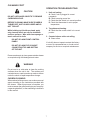
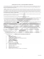
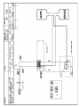
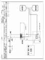
1
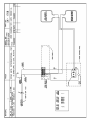
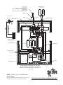
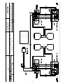
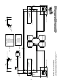
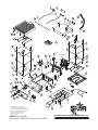
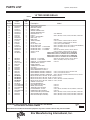
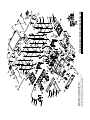
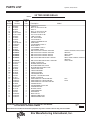
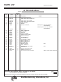
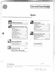
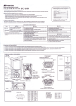
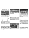
®
®
TWO-SIDED
GRILLS
230V MODELS
®
CG10, GR10
CG14 & GR14
CG28 & GR28 SERIES
Installation and
Operation
Instructions
®
2M-Z8985 Rev. D 4/19/2010
35.6 CM X 35.6 CM Grooved Grill
35.6 CM X 71.1 CM Grooved Grill
SAFETY SYMBOL
These symbols are intended to alert the user to the presence of
important operating and maintenance instructions in the manual
accompanying the appliance.
RETAIN THIS MANUAL FOR FUTURE REFERENCE
NOTICE
Using any part other than genuine Star factory supplied parts relieves the
manufacturer of all liability.
Star reserves the right to change specifications and product design without
notice. Such revisions do not entitle the buyer to corresponding changes,
improvements, additions or replacements for previously purchased
equipment.
Due to periodic changes in designs, methods, procedures, policies and
regulations, the specifications contained in this sheet are subject to change
without notice. While Star Manufacturing exercises good faith efforts to provide
information that is accurate, we are not responsible for errors or omissions
in information provided or conclusions reached as a result of using the
specifications. By using the information provided, the user assumes all risks in
connection with such use.
MAINTENANCE AND REPAIRS
Contact your local dealer for service or required maintenance. Please record the model number, serial
number, voltage and purchase date in the area below and have it ready when you call to ensure a faster
service.
Model No.
Serial No.
Voltage
Purchase Date
2
PRODUCT IDENTIFICATION
Star Manufacturing International, Inc. Two Sided Grills
230V Models:
GR10-230V- Smooth Top and Bottom Platens Aluminum, without Timer
GR10T-230V- Smooth Top and Bottom Platens Aluminum, with Timer
GR10I-230V- Smooth Top and Bottom Platens Cast Iron, without Timer
GR10IT-230V- Smooth Top and Bottom Platens Cast Iron, with Timer
CG10I-230V- Grooved Top and Bottom Platens Cast Iron, without Timer
CG10IT-230V-Grooved Top and Bottom Platens Cast Iron, with Timer
GR14-230V- Aluminum Smooth Top and Bottom Platens, without Timer
GR14T-230V- Aluminum Smooth Top and Bottom Platens, with Timer
GR14I-230V- Iron Smooth Top and Bottom Platens, without Timer
GR14IT-230V- Iron Smooth Top and Bottom Platens, with Timer
CG14-230V- Aluminum Grooved Top and Bottom Platens, without Timer
CG14T-230V- Aluminum Grooved Top and Bottom Platens, with Timer
CG14I-230V-Iron Grooved Top and Bottom Platens, without Timer
CG14IT-230V- Iron Grooved Top and Bottom Platens, with Timer
CG28I-230V Grooved Iron Platens without Timers
CG28IT-240V Grooved Iron Platens with 2 Timers
CG28IGT-240V Iron Platens, Grooved Top and Smooth Bottom without Timers
GR28I-240V Smooth Iron Platens without Timers
GR28IT-240V Smooth Iron Platens with 2 Timers
GENERAL INSTALLATION DATA
CAUTION
This equipment is designed and sold for
commercial use only by personnel trained and
experienced in its operation and is not sold for
consumer use in and around the home nor for
use directly by the general public in food service
locations.
Before using your new equipment, read
and understand all the instructions & labels
associated with the unit prior to putting it into
operation. Make sure all people associated with
its use understand the units operation & safety
before they use the unit.
All shipping containers should be checked for
freight damage both visible and concealed. This
unit has been tested and carefully packaged to
insure delivery of your unit in perfect condition.
If equipment is received in damaged condition,
either apparent or concealed, a claim must be
made with the delivering carrier.
Concealed damage or loss - if damage or loss is
not apparent until after equipment is unpacked, a
request for inspection of concealed damage must
be made with carrier within 15 days. Be certain
to retain all contents plus external and internal
packaging materials for inspection. The carrier
will make an inspection and will supply necessary
claim forms.
VENTILATION AND CLEARANCES
The installation of any components such as
a vent hood, grease extractors, and/or fire
extinguishing systems, must conform to their
applicable nationally recognized installation
standards and/or local building codes.
ELECTRICAL CONNECTION
CAUTION
Before making any electrical connection be sure
to read data plate which is located at the bottom
of the unit.
ELECTRICAL GROUNDING
INSTRUCTIONS
This unit is equipped with a CEE-7/VII Cord, use
the proper (grounding) plug that provides proper
protection against shock hazard and must be
plugged directly into a properly grounded 3-prong
receptacle. For your protection we recommend
that a qualified electrician be consulted in regards
to any electrical conserns or installations. He/she
should be familiar with electrical installations and
all electric codes. Proper connections and power
supply are essential for efficient performance.
CAUTION
DO NOT CUT OR REMOVE THIS PLUG OR
GROUNDING PRONG FROM THE PLUG.
CAUTION
CONNECT/PLUG UNIT INTO DEDICATED
A.C LINE ONLY SPECIFIED ON THE DATA
PLATE OF THE UNIT.
ELECTRICAL SPECIFICATIONS
Rated Wattage
Model No.
Volts
GR 10
GR 10I
CG 10I
GR 14
GR 14I
CG 14
CG 14I
CG 28I
GR 28I
230
230
230
230
230
230
230
230
230
Amps
NEMA Plug
1653 7.2
1653 7.2
1653 7.2
1653 7.2
3306
14.2
1653 7.2
3306
14.2
6612
28.7
6612
28.7
INITIAL START UP
Level unit using the adjustable feet under the unit
(approximately 1/2" adjustment).
Before using the unit for the first time, clean and
heat for approximately 30 minutes. The grill may
emit a small amount of smoke as the cooking
surfaces reach 300-350°F (148-176°C). Do
not be alarmed, as the smoke is caused by oils
associated with the manufacturing process and
will stop when the grill reaches 400°F (204°C).
This will take approximately 30 minutes. Brush
off any debris from the grilling surfaces. Allow
grill to cool prior to placing it in its permanent
position.
SETTING THE TEMPERATURE
The thermostat control knob is used to set the
temperature to your requirements. The maximum
set point is 550°F (288°C), the minimum set point
is 175°F (79°C). See Knob Settings.
SETTING THE TIMER (TIMER MODELS ONLY)
(9 MIN. 59 SEC. MAX)
The timer may be factory pre-set. If changes are
required follow these simple steps:
1. To increase time, press and hold the
(UP) button. The Start/Stop button can now be used to increase the cooking time.
2. To decrease time, press and hold the (DOWN) button. The Start/Stop button can now be used to decrease cooking time.
SEASONING THE COOKING SURFACES
KNOB SETTING
FIRST TIME SEASONING
Knob Position
Follow your company/corporate guidlines for
seasoning cooking surfaces. or
1. Bring the grill to 300°F and leave it on while doing the next three steps.
2. Brush the cooking surfaces with a release agent. If using an aerosol agent,
first apply into a cup and then brush onto cooking surface.
3. Let sit for 20 minutes, and then wipe clean using a warm damp cloth.
CEE-7/VII
CEE-7/VII
CEE-7/VII
CEE-7/VII
CEE-7/VII
CEE-7/VII
CEE-7/VII
CEE-7/VII
CEE-7/VII
DAILY SEASONING
The grill should not require much seasoning while
in use. In most cases, brush a light coating of the
baking release agent in the morning and occasionally
throughtout the day will be enough to prevent any
sticking. It is not necessary to spray before grilling
each item.
1-2
3
4
5
6
7
8
9
10
Approx. Temp
175°F / 79°C
200°F / 93°C
250°F / 121°C
300°F / 148°C
350°F / 176°C
400°F / 204°C
450°F / 232°C
500°F / 260°C
550°F / 287°C
ON/OFF ROCKER SWITCH
(TIMER MODELS ONLY)
The switch turns the unit on and off. The switch
has three positions:
With the switch in this position, both top and bottom platens will heat.
With the switch in this position, neither platen will heat.
With the switch in this position only bottom platen will heat.
DAILY OPERATION
Always allow 10-20 minutes of preheat time
before loading the unit with product. Failure
to allow sufficient preheat time will result in
unsatisfactory cooking of the first load.
Check the power cord to insure that it is plugged
into a proper outlet.
Check that the switch and thermostat control are
turned on.
Set the unit's ON/OFF rocker switch to desired
position.
Set the thermostat control knob to desired
temperature.
OPERATING HINTS AND SAFETY
MONTHLY LUBRICATION/INSPECTION
Apply two (2) drops of non-toxic mineral or
vegetable oil to counter balance shoulder rivets
and plastic spacers.
Check and clean brass rollers to make sure they
are rolling and not sliding on the cam surfaces of
the counterbalance.
Check the bolts, screws and nuts, tighten if
necessary.
CLEANING
Begin cleaning procedure by using the operating
procedures within your organization, or follow the
steps below:
1. If particles adhere to the cooking surface during
the day, scrape them off with a spatula.
NOTE: It is best not to let food cook onto the
grill, as food build-up on the grill will increase
sticking and smoking. In addition, carbon may
build up on the grill surface and reduce the
cooking efficiency.
CARBON BUILDUP: A black matter that forms on
or near the cooking surface. Generally this is
releasing agents that has cooked itself to the
surface. After a period of time, without carbon
cleaning this material may start flaking off. When
that happens, follow the "Carbon Cleaning"
procedures.
2. At the end of the day, wipe down all surfaces
with a warm, damp cloth and mild detergent,
then dry.
Disconnect power to the unit with the switch at
the end of each day of operation.
Do not leave the unit in operation without an
attendant.
Turn thermostat down to 200°F (93°C) during idle
periods. It will take only a few minutes to regain
operating temperature.
DO NOT IMMERSE OR LET THE UNIT
STAND IN WATER.
Use spatula to push excess grease into grease
drawer after each load of food is cooked.
This will reduce smoking of hot grease and
carbonizing.
DO NOT HOSE DOWN THE UNIT OR
THE TABLE/COUNTER IF THE UNIT IS
ON THE TABLE/COUNTER.
Do not leave the unit at high temperature when
not in use or during idle periods. This will cause
food particles and grease film to carbonize.
CAUTION
KEEP AWAY FROM RUNNING WATER.
"Season" cooking surfaces with non-salted
vegetable oil to reduce product sticking.
CLEANING CON'T
OPERATION TROUBLESHOOTING
CAUTION
DO NOT USE SHARP OBJECTS TO REMOVE
CARBON BUILD-UP.
BEFORE CLEANING MAKE SURE POWER IS
TURNED OFF, UNIT IS UNPLUGGED AND IS
NOT TOO HOT.
While holding top lid with one hand, apply
only cleaners which are safe for aluminum
and iron surfaces. Wipe with clean sponge or
towel until unit is clean.
DO NOT SPLASH FRONT CONTROL PANEL!
DO NOT SPLASH FLEX CONDUIT CONNECTING TOP AND BOTTOM
OF THE UNIT.
1. Unit not heating.
A.Check if unit is plugged in correct receptacle.
B.Check incoming power line.
C.Check that the switch is in correct position.
D.Check that thermostat is set to proper temperature.
2. Top platen not heating.
A.Check that the rocker switch is in correct postion.
3. Counter balance roller not rolling.
A.Clean rollers.
If unit still does not operate contact the factory
or one of its representatives or a local service
company for service or required maintenance.
Remove and empty to clean grease catcher drawer
as required using mild detergent and water.
WARNING
Do not use ice or cold water to clean the cooking
surfaces when the unit is hot. The surfaces are
cast aluminum or cast iron and may crack or deform
under the shock of rapid temperature change.
CARBON CLEANING
When carbon build up occurs, use a carbon removal
agent according to the instructions provided with
the cleaner. When this process is complete, you
must re-season the grill according to your company/
corporate guidelines, or the seasoning instructions
in this manual.
INTERNATIONAL ONE (1) YEAR EQUIPMENT WARRANTY
All workmanship and materials in “STAR” products are warranted for a period of one year from the date shipped from the factory or
one year from the date shown on the proof of purchase of the end-user when purchased through an authorized “STAR” dealer/distributor in a commercial foodservice location.
“STAR’s” obligation under this warranty is limited to the replacement of the defective part(s) only without charge. This warranty is
void if damage occurs from improper installation, misuse or abuse, disassembly or tampering of unit for any purpose other than repair
by a qualified service agent, wrong voltage, incorrect or fluctuating voltage conditions, wrong gas, improper gas or gas conditions,
operated contrary to the installation and operating instructions, operated in an application for which the unit is not suited, or if the unit
is not maintained and/or cleaned in a suitable manner.
Any expense in connection with installation, or any cost of making adjustments on a unit to conform to electric or gas service at the
point of installation, are not covered by this warranty.
* The warranty period for the JetStar series six (6) ounce popcorn machines is two (2) years.
* The warranty period for the Chrome-Max Griddles is five (5) years on the griddle surface. See detailed warranty provided with unit.
* The warranty period for Teflon/Dura-Tec coatings is one year under normal use and reasonable care. This warranty does not
apply if damage occurs to Teflon/Dura-Tec coatings from improper cleaning, maintenance, use of metallic utensils, or abrasive
cleaners. This warranty does not apply to the “non-stick” properties of such materials.
* This warranty is not valid on Conveyor Ovens unless a “start-up/check-out has been performed by a Factory Authorized Technician.
In order to make a claim under this warranty; a warranty report must be filed with Star Manufacturing International Inc. in St. Louis,
Missouri, U.S.A. by the dealer/distibutor through which product was purchased. All details, including serial number and model number of the defective unit, must be included. Failure to file a claim within a 120 Day time period may result in the claim being refused.
“STAR” may forego the necessity of returning the part for inspection dependent upon the expense involved. However, “STAR”
requires defective parts to be held in the claimant’s possession for a period of ninety (90) days for possible inspection by a “STAR”
representative or designated inspector .
The foregoing warranty is lieu of any and all other warranties, expressed or implied, and constitutes the entire warranty.
PARTS WARRANTY
Parts that are sold for out-of-warranty repair are warranted for a period of ninety days. The part only is warranted; no labor.
SERVICES NOT COVERED BY WARRANTY
1.
2.
3.
4.
5.
6.
7.
8.
9.
10.
11.
12.
13.
14.
15.
16.
Labor
Mileage and/or travel time
Installation and/or adjustment of equipment
Operation contrary to the installation and operating instructions
Cleaning of equipment
Seasoning of griddle plates
Voltage conversions/adjustments
Gas conversions
Pilot light conversion/adjustments
Thermostat calibration/adjustments
Resetting of circuit breakers or safety controls
Replacement of bulbs/lamps
Replacement of fuses
Damages due to improper installation
Damages from abuse or misuse
Damage created by acts of God, Acts of War, or Civil Disturbance
08-05 rms
10
11
TOP ELEMENT
15 AMP PLUG
NEMA 5-15P ON ALL 120V UNITS.
NEMA 6-15P ON 240V, 1,800 WATT UNITS.
20 AMP PLUG
NEMA 6-20P ON 240V, 3,600 WATT UNITS.
GREEN
INLET IEC 320 16A
WHITE
BLACK
TERMINAL BLOCK
TRANSFORMER
G
L
N
20
9
18
10
8
1
19
6
5
8
2
13
4
7
6
230V UNITS
BOTTOM ELEMENT
THERMOSTAT
9
3
INDICATOR LIGHT
(POWER ON)
10
12
E2 E1
11
7
3
13
12
3
2
4
11
5
1
SWITCH
TIMER BOARD
FOR REFERENCE
WIRING DIAGRAM IS SHOWN AS UNIT IS ASSEMBLED
WITH THE BOTTOM PLATE REMOVED. ITEMS ARE IN
GENERAL LOCATION BUT MAY BE RELOCATED OR SCALED
FOR CLARITY.
MODEL: CG/GR, 10/14, 120V/230/240V,
WITH TIMER
THIS DRAWING CONTAINS INFORMATION CONFIDENTIAL TO STAR MFG. INT'L. INC.
NO REPRODUCTION OR DISCLOSURE OF ITS CONTENTS IS PERMITTED.
STAR MANUFACTURING INTERNATIONAL INC.
SK2001
12
Rev A
8/10/2004
13
CK.
DATE
LIMITS UNLESS OTHERWISE NOTED
FRACTIONS 1/64 DECIMALS .005
DR.
MATERIAL
7-05-99
-
BOTTOM ELEMENT
(ELEMENTO MAS BAJO)
BOTTOM ELEMENT
(ELEMENTO MAS BAJO)
1
1
1
1
1
1
1
1
QTY.
(CANTIDAD)
TOP ELEMENT
(ELEMENTO MAS ALTO)
D9-GR0058
D9-GR0059
D9-GR0060
D9-GR0064
D9-GR0057
D9-GR0065
D9-GR0106
D9-GR0107
PART NO.
(PARTE NO.)
TOP ELEMENT
(ELEMENTO MAS ALTO)
4
2,5
1,8
3,6,7
10
9
11
12
WIRE NO
(HILO NO.)
10 SUNNEN DRIVE ST. LOUIS, MO 63143
STAR MFG. INTERNATIONAL, INC.
FINISH
SK-1709
PART NO.
TITLE WIRE DIAGRAM 240V 7200W UL W/TIMER
MODEL NO.
GR/CG28IT-240V
CG28ITGT-240V
14
2
3
20
FRONT CONTROL PANEL
REAR PANEL
TERM BLOCK
(BLOQUE TERMINAL)
L
N
G
NEMA L6-30 P PLUG
NO REPRODUCTION OR DISCLOSURE OF ITS CONTENTS IS PERMITTED.
15
14
240V UNITS
230V UNITS
INLET IEC 320 16A
THIS DRAWING CONTAINS INFORMATION CONFIDENTIAL TO STAR MFG. INT'L. INC.
MODEL: GR-CG28I-230/240V
PILOT
LIGHT
T-STAT
1
WHITE
(BLANCO)
BLACK
(NEGRO)
GREEN
(VERDE)
18
19
BOTTOM ELEMENT
(ELEMENTO MAS BAJO)
TOP ELEMENT
(ELEMENTO MAS ALTO)
1
1
1
1
1
QTY.
(CANTIDAD)
1
1
1
1
1
1
2
2
2
QTY.
(CANTIDAD)
BOTTOM ELEMENT
(ELEMENTO MAS BAJO)
TOP ELEMENT
(ELEMENTO MAS ALTO)
1 D9-GR0103
2 D9-GR0104
3 D9-GR0105
14 D9-GR0106
15 D9-GR0107
WIRE NO PART NO.
(HILO NO.) (PARTE NO.)
4 D9-GR0058
2,5 D9-GR0059
1,8 D9-GR0060
3,6,7 D9-GR0064
10 D9-GR0057
9 D9-GR0065
18 D9-GR0250
19 D9-GR0251
20 D9-GR0252
WIRE NO PART NO.
(HILO NO.) (PARTE NO.)
TERM BLOCK
(BLOQUE TERMINAL)
FRONT CONTROL PANEL
REAR PANEL
G
N 18
PILOT
LIGHT
T-STAT
2
3
SK1710
Rev B
8/09/2004
STAR MANUFACTURING INTERNATIONAL INC.
INLET IEC 320 16A
20
L
19
1
57
4
5
3
1
2
10
6
7
8
11
12
13
54
53
14
9
54
52
PR
EC
Favo
o
FAV
OR
SUP NO
TOC
CAL ERI
AR
IEN FIC
IE
TE
roc
ia
gu
e
GR
er
ase
de
que
ncad
a
an
teng
ient
LI
AU
rde
dejar
esta
No
m
Main
corr
PE
no
la
sobr
sum
base
e
ergi
r
CI
ON
este
agua
con
a.
lejos
agu de
a.
O
Do
imm
NO
T
run
nin
R
TIO
or
d
dow
in
N
let
wate
r.
n.
awa
g
GE
erse
stan
not
hos
e
T
24
CAU
not
base
Do
Kee
p
DAN
DO
HO
y
wat
15
from
er.
SU TOU
RFA CH
CE
.
51
16
56
16
28
27
Hinge Mech.
29
17
18
19
30
17
20
50
26
25
21
19
55
49
47
44
58
31
48
59
TO
P
BO &
ON TTOM
(I)
PO
BO
TTO
ON M
WER
OF
F
PO
PR
WER
33
ON
O-
MA
X
TIM
E
STAR
42
39
T
STOP
46
22
32
23
45
41
37
40
38
SOME ITEMS ARE INCLUDED FOR
ILLUSTRATIVE PURPOSES ONLY AND IN
CERTAIN INSTANCES MAY NOT BE AVAILABLE
35
This drawing contains information confidential
to Star Manufacturing International, Inc.
No reproduction or disclosure of its
contents is permitted.
STAR MANUFACTURING INTERNATIONAL, INC.
MODEL GR10I,CG10I,
GR14,GR14I, GR14ITTC,CG14,CG14I,CG14IGT
SK1687
15
REV. F
4/15/10
PARTS LIST
April 19, 2010, Rev D
MODEL
Key
Number
Part
Number
Number
Per
Unit
10' TWO SIDED GRILLS
Description
Model
1
2C-Z2992
2
SCREW, HANDLE
2
2V-Z2990
1
HANDLE - 10”
3
2B-Z2988
2
ARM - 10”
4
2C-08-07-0040
4
NUT
4
2C-08-07-0262
4
WASHER
5
2C-Z2992
4
SCREW, ARM TO BRACKET
6
D9-Z2038
1
HOUSING-TOP-10”
7
2C-Z3200
2
PIN - TOP HOUSING
8
2C-Z2855
2
RETAINER RING
9
2C-08-07-0040
2
1/4” NUT, USE PART NUMBER 2C-Z2820
10
24-Z3827
1
CONDUIT KEEPER PLATE
11
2C-Z3780
2
CONDUIT RETAINER
12
2E-Z2898
1
CONDUIT ASSY. - PTFE
13
2E-Z3768
1
CONDUIT LOCKNUT
14
D9-04-GR-0166
1
WIRE MOUNT
15
D9-GR0084
1
TOP RETAINING PLATE AY/10
16
D9-Z2908
2
INSULATION - 10”
17
2A-Z6604
8
SPACER - INSULATED PLATE
18
D9-Z2772
1
TOP ELEMENT/INS. PLATE/10
19
2C-08-07-0285
8
SCREW, ELEMENT RET. PLATE
20
PS-Z1978
1
TOP ELEMENT, HEATING, 800W/120
GR10I, GR10IT, CG10I, CG10IT, GR10, GR10T
PS-Z2019
1
TOP ELEMENT, HEATING, 800W/240V
GR10I, GR10IT, CG10I, CG10IT, GR10, GR10T
21
PS-GR0348
1
KIT, 2F-Z1928 CSTN, SM. TOP,ALUM.-10” GR10, GR10T
PS-GR0349
1
KIT, 2F-Z1932 CSTN, SM. TOP, IRON-10” GR10I, GR10IT
PS-GR0347
1
KIT, 2F-Z1934 CASTING, GR. TOP, IRON-10”
CG10I, CG10IT
22
2K-Y3240
1
BUSHING 90 SR 17-2
GR10, GR10T, GR10I, GR10IT, CG10I, CG10IT,
(120V MODELS),
GR10, GR10T, GR10I, GR10IT, CG10I,CG10IT
(240V MODELS)
23
2E-Z2770
1
CORD, POWER, 14-3, 6-15P
GR10T, GR10, GR10I, GR10IT, CG10I, CG10IT,
(240V MODELS)
2E-Z2935
1
CORD SET 14/3 NEMA 5-15P
GR10T, GR10, GR10I, GR10IT, CG10I, CG10IT,
(120V MODELS)
2E-Z4119
1
CORD, POWER, 12/3 5-20P
120VC MODELS
24
2M-Z2620
1
LABEL CAUTION, BI-LINGUAL
25
2E-05-07-0350
1
TRANSFORMER 230V/10V 6VA
240V MODELS
2E-05-07-0351
1
TRANSFORMER 115/10V 6VA
120V MODELS
26
2E-Z2894
1
TERMINAL BLOCK
27
D9-GR0053
1
REAR LINER ASSY. - 10”/BOT
28
2C-1512
2
SCREW - PIN ASSY
29
2V-Z3252
1
PIN ASSY - TOP HOUSING STOP
30
2R-Z2907
1
COUNTERBALANCE -10”-IRON
2R-Z3333
1
COUNTERBALANCE -10”-ALUM.
31
D9-GR0032
2
TORQUE BOX ASSY.
32
D9-Z3071
4
BRACKET-HANDLE
33
2V-Z3072
2
HANDLE - SIDE
34
D9-GR0034
1
GREASE CABINET ASSY.
35
D9-GR0517
1
GREASE DRAWER ASSY
37
D9-GR0246
1
BASE BOTTOM - 10”
230V MODELS
38
2A-Z1485
4
FOOT, 1” ADJUSTABLE
39
D9-GR0062
1
BODY ASSY. - 10”
40
2J-Z1836
1
TIMER CONTROL
CG10T, CG10IT, GR10T, GR10IT
IMPORTANT: WHEN ORDERING, SPECIFY VOLTAGE OR TYPE DESIRED
INCLUDE MODEL AND SERIAL NUMBER
Some items are included for illustrative purposes only and in certain instances may not be available.
Star Manufacturing International, Inc.
16
PAGE 1
OF
2
PARTS LIST
April 19, 2010, Rev D
MODEL
Key
Number
Part
Number
Number
Per
Unit
10' TWO SIDED GRILLS
Description
Model
41
2K-Z1971
4
SPACER
CG10T, CG10IT, GR10T, GR10IT
42
2J-Y6689
1
PILOT LIGHT, 120V GR10, GR10I, CG10I (120V MODELS)
2J-Z2329
1
PILOT LIGHT, 240V
GR10, GR10I, CG10I (240V MODELS)
43
D9-GR0051
1
FACEPLATE ASSY. - 10” w/TIMER
GR10T, GR10IT, CG10IT
D9-GR0109
1
FACEPLATE ASSY. - 10” NO TIMER
GR10, GR10I, GR10I, CG10I, CG10I
44
2E-Z6863
1
SWITCH 3 POS CG10T, CG10IT, GR10T, GR10IT
PS-GR0223
1
SWITCH CG10IT-120V W/SERIAL NUMBERS BELOW CGA24279
CG10IT-240V W/SERIAL NUMBERS BELOW CGA20294
GR10IT-120V W/SERIAL NUMBERS BELOW GRA27109
CG10TJD-240V W/SERIAL NUMBERS BELOW CGA29997
GR10T-240V W/SERIAL NUMBERS BELOW GRA03390
45
2M-Z6881
1
OVERLAY - 10” w/TIMER
GR10T, GR10IT, CG10IT
2M-Z3051
1
OVERLAY - 10” NO TIMER
GR10, GR10I, CG10I
46
2I-05-07-0013
1
RUBBER BOOT, SWITCH
47
2R-Z1854
1
KNOB-CONTROL
48
2T-6447
1
THERMOSTAT 118V-236V
49
2A-Z3026
1
HALF CLIP
50
D9-Z2774
1
BTM. INSULATION RET. PLT. 10”
51
D9-Z2773
1
BTM ELEMENT RET. PLATE 10”
52
2N-Z1979
1
BTM ELEMENT, HEATING, 1000W/120
GR10I, GR10IT, CG10I, CG10IT, GR10, GR10T
52
2N-Z2020
1
BTM ELEMENT, HEATING, 1000W/240
GR10I, GR10IT, CG10I, CG10IT, GR10, GR10T
53
PS-GR0359
1
KIT, 2F-Z1929 CSTG, SM.BOT., ALUM.-10”GR10, GR10T
PS-GR0360
1
KIT, 2F-Z1933 CSTG, SM. BOT., IRON-10” GR10I, GR10IT
PS-GR0358
1
KIT, 2F-Z1935 CSTG, GR. BOT., IRON-10” CG10I, CG10IT
54
2C-Z5883
8
SCREW 10-24X1/2 FZA
55
PS-GR134
2
KIT, ROLLER BEARING KIT
IMPORTANT: WHEN ORDERING, SPECIFY VOLTAGE OR TYPE DESIRED
INCLUDE MODEL AND SERIAL NUMBER
Some items are included for illustrative purposes only and in certain instances may not be available.
Star Manufacturing International, Inc.
17
PAGE 2
OF 2
PARTS LIST
MODEL
Key
Number
Part
Number
Number
Per
Unit
April 19, 2010, Rev D
14' TWO SIDED GRILLS
Description
Model
1
2C-Z2992
2
SCREW, HANDLE
2
2V-Z2989
1
HANDLE - 14”
2V-Z3413
1
HANDLE - 14” S.S.
GR14, GR14T
SER. # GRC00112 - 00138,
GRC00778 - 00858,
GRC00864 - 01256
3
2B-Z2987
2
ARM - 14”
2B-Z3336
2
ARM GR14SN
4
2C-08-07-0040
4
NUT
2C-08-07-0262
4
WASHER
5
2C-Z2992
4
SCREW, ARM TO BRACKET
6
D9-Z2036
1
HOUSING-TOP-14”
7
2C-Z3200
2
PIN - TOP HOUSING
8
2C-Z2955
2
RETAINER RING
9
2C-08-07-0040
2
1/4” NUT, USE PART NUMBER 2C-Z2820
10
2A-Z3827
1
CONDUIT KEEPER PLATE
11
2C-Z3780
2
CONDUIT RETAINER
12
2E-Z2898
1
CONDUIT ASSY. - PTFE
13
2E-Z3768
1
CONDUIT LOCKNUT
14
D9-04-GR-0166
1
WIRE MOUNT
15
D9-GR0079
1
TOP RETAINING PLATE AY/14
16
D9-Z2888
2
INSULATION - 14”
17
2A-Z6604
8
SPACER - INSULATED PLATE
18
D9-Z2075
1
TOP ELEMENT/INS. PLATE/14
19
2C-08-07-0285
8
SCREW, ELEMENT RET. PLATE
20
PS-Z1980
1
TOP ELEMENT, HEATING, 800W/120
CG14, CG14T, GR14, GR14T, CG14IT-120V
2N-Z2021
1
TOP ELEMENT, HEATING, 800W/240V
CG14, CG14T, GR14, GR14T
PS-Z2391
1
TOP ELEMENT, HEATING, 1800W/240
GR14I, GR14IT, CG14IGT, CG14ITGT, CG14I, CG14IT
21
PS-GR0350
1
KIT, 2F-Z7786 CSTG, SM. TOP, ALUM.-14” GR14, GR14T
PS-GR0351
1
KIT, 2F-Z1946 CSTG, GR. TOP, ALUM.-14” CG14, CG14T
PS-GR0352
1
KIT, 2F-Z1948 CSTG, SM. TOP, IRON-14” GR14I, GR14IT
PS-GR0353
1
KIT, 2F-Z1950 CSTG, GR. TOP, IRON-14” CG14IGT, CG14ITGT
22
2K-3485
1
BUSHING-HEYCO #SR-9P-2
GR14I, GR14IT, CG14IGT, CG14ITGT, CG14I,
CG14IT (240V MODELS)
2K-Y2968
1
BUSHING 7W-2
CG14IT-120V
2K-Y6764
1
BUSHING
CG14IT-120VC (CANADIAN)
2K-Y3240
1
BUSHING
CG14, CG14FT, CG14T, GR14, GR14SN,
GR14T, (120V &120VC)
23
2E-Z2905
1
CORD SJTO 12/2 NEMA 6-20P
GR14I, GR14IT, CG14IGT, CG14ITGT, CG14I,
CG14IT (240V MODELS)
2E-Z2935
1
CORD SET 14/3 NEMA 5-15P
120V MODELS
2E-Z4119
1
CORD, POWER 12/3 5-20P
120VC (CANADIAN) MODELS
24
2M-Z2620
1
LABEL CAUTION, BI-LINGUAL
25
2E-05-07-0350
1
TRANSFORMER 230V/10V 6VA
240V MODELS
2E-05-07-0351
1
TRANSFORMER 115/10V 6VA
120V MODELS
26
2E-Z2894
1
TERMINAL BLOCK
27
D9-GR0054
1
REAR LINER ASSY. - 14”/BOT
CG14, GR14, CG14T, GR14T
D9-GR0080
1
REAR LINER ASSY. - 14”/REAR
CG14I, GR14I, CG14IGT, CG14IT, GR14IT, CG14ITGT
D9-GR0201
1
REAR LINER ASSY.
CG14IT (120V)
28
2C-1512
2
SCREW - PIN ASSY
29
2V-Z3252
1
PIN ASSY - TOP HOUSING STOP
30
2R-Z2896
1
COUNTERBALANCE -14”-IRON
2R-Z2897
1
COUNTERBALANCE -14”-ALUM.
IMPORTANT: WHEN ORDERING, SPECIFY VOLTAGE OR TYPE DESIRED
INCLUDE MODEL AND SERIAL NUMBER
Some items are included for illustrative purposes only and in certain instances may not be available.
Star Manufacturing International, Inc.
18
PAGE 1
OF 2
PARTS LIST
MODEL
Key
Number
Part
Number
Number
Per
Unit
April 19, 2010, Rev D
14' TWO SIDED GRILLS
Description
Model
31
D9-GR0032
2
TORQUE BOX ASSY.
32
D9-Z3071
4
BRACKET-HANDLE
33
2V-Z3072
2
HANDLE - SIDE
34
D9-GR0034
1
GREASE CABINET ASSY.
35
D9-GR0517
1
GREASE DRAWER ASSY
37
D9-GR0247
1
BASE BOTTOM - 14”
230V MODELS
38
2A-Z0314
4
FOOT, 4”
GR14I, GR14IT, CG14I, CG14IT, CG14IGT, CG14ITGT
2A-Z1485
4
FOOT, 1” ADJUSTABLE
39
D9-GR0061
1
BODY ASSY. - 14”
D9-GR0184
1
BODY ASSY GR14SN
40
2J-Z1836
1
TIMER CONTROL
CG14T, CG14IT, CG14IGT, GR14T, GR14IT
41
2K-Z1971
4
SPACER
CG14T, CG14IT, CG14IGT, GR14T, GR14IT
42
2J-Y6689
1
PILOT LIGHT, 120V CG14, GR14 (120V MODELS)
2J-Z2329
1
PILOT LIGHT, 240V
GR14I, CG14IGT, CG14I, CG14, GR14 (240V MODELS)
43
D9-GR0108
1
FACEPLATE ASSY. - 14” NO TIMER
GR14I, CG14IGT, CG14I, CG14, GR14
D9-GR0178
1
FACEPLATE ASSY. - 14” 2 TIMERS
CG14-2T
D9-GR0210
1
FACEPLATE ASSY. - 14” w/TIMER
GR14IT, CG14ITGT, CG14IT, CG14T, GR14T
44
2E-Z6863
1
SWITCH 3 POS CG14T, CG14IT, CG14IGT, GR14T, GR14IT
PS-GR0224
1
SWITCH
CG14T-120V W/SERIAL NUMBERS BELOW CGC25308
CG14IT-120V W/SERIAL NUMBERS BELOW CGC24701
GR14T-120V W/SERIAL NUMBERS BELOW GRC23789
CG14IT-240V W/SERIAL NUMBERS BELOW CGC24559
45
2M-Z6870
1
OVERLAY - 14” w/TIMER
GR14IT, CG14ITGT, CG14IT, CG14T, GR14T
2M-Z3050
1
OVERLAY - 14” NO TIMER
GR14I, CG14IGT, CG14I, CG14, GR14
2M-Z3816
1
OVERLAY - 14” w/2 MANUAL TIMERS
CG14-2T
46
2I-05-07-0013
1
RUBBER BOOT, SWITCH
47
2R-Z1854
1
KNOB-CONTROL
48
2T-6447
1
THERMOSTAT 118V-236V
49
2A-Z3026
1
HALF CLIP
50
D9-Z8082
1
BTM. INSULATION RET. PLT. 14”
51
D9-Z8082
1
BTM ELEMENT RET. PLATE 14”
52
2N-Z1981
1
BTM ELEMENT, HEATING, 1000W/120
CG14, CG14T, GR14, GR14T, CG14IT-120V
2N-Z2022
1
BTM ELEMENT, HEATING, 1000W/240
CG14, CG14T, GR14, GR14T
2N-Z2392
1
BTM ELEMENT, HEATING, 1800W/240V GR14I, GR14IT, CG14IGT, CG14ITGT, CG14I, CG14IT
53
PS-GR0361
1
KIT, 2F-Z1945 CSTG, SM. BOT., ALUM.-14”GR14, GR14T
PS-GR0362
1
KIT, 2F-Z1947 CSTG, GR. BOT., ALUM.-14”CG14, CG14T
PS-GR0363
1
KIT, 2F-Z1949 CSTG, SM. BOT., IRON-14” GR14I, GR14IT, CG14IGT, CG14ITGT
PS-GR0364
1
KIT, 2F-Z1951 CSTG, GR. BOT., IRON-14” CG14I, CG14IT
54
2C-Z5883
8
SCREW 10-24X1/2 FZA
55
PS-GR134
2
ROLLER BEARING KIT
NI
2C-08-WB-0008
2
NUT-TIMER (NOT SHOWN)
CG14-2T
NI
2C-09-WB-0005
2
BEZEL (NOT SHOWN)
CG14-2T
NI
2P-09-WB-0007
2
TIMER BELL (NOT SHOWN)
CG14-2T
NI
2P-Z2911
1
PLUG DOUBLE D .75x.625
CG14I, GR14I, CG14IGT, CG14IT, GR14IT, CG14ITGT
NI
2R-09-WB-0006
2
KNOB-BLACK (NOT SHOWN)
CG14-2T
NI
2V-Z3027
2
CROSS SUPPORT (NOT SHOWN)
GR14I, GR14IT, CG14I, CG14IT, CG14IGT, CG14ITGT
NI
D9-Z3028
1
SIDE SUPPORT (NOT SHOWN)
GR14I, GR14IT, CG14I, CG14IT, CG14IGT, CG14ITGT
NI
D9-Z3029
1
PART SUPPORT (NOT SHOWN)
GR14I, GR14IT, CG14I, CG14IT, CG14IGT, CG14ITGT
IMPORTANT: WHEN ORDERING, SPECIFY VOLTAGE OR TYPE DESIRED
INCLUDE MODEL AND SERIAL NUMBER
Some items are included for illustrative purposes only and in certain instances may not be available.
Star Manufacturing International, Inc.
19
PAGE 2
OF 2
20
46
39
40
41
42
43
38
(O
ER
OFF
POW
)
ON
(I)
ax
-M
Pro
TIME
START
STOP
11
36
37
43A
10
STOP
START
TIME
31
(O
ER
OFF
POW
)
ON
(I)
35
NO REPRODUCTION OR DISCLOSURE OF ITS CONTENTS IS PERMITTED.
THIS DRAWING CONTAINS INFORMATION CONFIDENTIAL TO STAR MFG. INT'L. INC.
MODEL:GR28I,CG28I,CG28IGT-240V
44
45
47
1A
1
2
2A
48
26
18
8
7
2B
3
25
o
este
N
32
not
from
Do
Do
hose
in
or
water
.
let
ION
UT
se
23
.
stand
immer
CA
not
down
base
6
wate
r.
away
ing
Keep
runn
24
ER
NG
DA
HOT NOT
SUR TOUC
FAC H
E.
DO
CIO
CAU
rgir
agua
base
sume
PRE
9
.
con
era
rocia
la
no
sobre
que
de
ada
dejar
Favor
estanc
ngu
agua. de
lejos
ma
de
34
33
2C
nte
ngase
Mainte
corrie
RO
LIG
PE
R
SUPE NO
TOCA
CALIE RIFIC
R
NTE
IE
FAVO
No
5
20
35
30
17
21
4
19
5A
37
28
15
8
14
13
17
27
18
18A
1
6
12A
2
11
8
50
9
49
7
5A
3
PE
nte
o
dejar
Favor
.
la
no
CAU
rgir
este
agua
base
sume
PRE
sobre
que
de
5
era
con
ada
estanc
rocia
ngu
agua. de
lejos
No
ma
de
ngase
Mainte
corrie
LIG
RO
10
SUPE NO
TOCA
CALIE RIFIC
R
NTE
IE
FAVO
R
N
DA
NG
HOT NOT
SUR TOUC
FAC H
E.
DO
CIO
ER
SK1700
Rev B
05/06/05
not
from
Do
Do
.
in
se
or
water
immer
.
ION
let
CA
UT
not
stand
down
base
hose
4
wate
r.
away
ing
Keep
runn
STAR MANUFACTURING INTERNATIONAL INC.
29
24
22
16B
19A
21
16
36
25
20
16A
12
PARTS LIST
MODEL
Key
Number
Part
Number
Number
Per
Unit
April 19, 2010, Rev D
28' TWO SIDED GRILLS
Description
Model
1
2M-Z2989 2
HANDLE, 14”
1A
2C-Z2992
4
BOLT 1/4" 20X1 PHP STL NP
2
2B-Z2987 4
ARM, 14”
2A
2C-Z2992
8
BOLT 1/4" 20X1 PHP STL NP
2B
2C-08-07-0262
8
WASHER 1/4" INT STL NP
2C
2C-08-07-0040
8
NUT 1/4"-20 ACHD STL NP
3
2M-Z2620 2
LABEL, CAUTION
4
2C-Z2820 4
PIN, TOP HOUSING
5
D9-Z2306 2
TOP HOUSING 14”
5A
2A-Z3827
2
CONDUIT STAMPING PLATE
6
D9-04-GR-0166 2
WIRE MOUNT
7
D9-GR0079 2
TOP RETAINING PLATE 14”
8
D9-Z2888 4
INSULATION 14”
9
D9-Z2075 2
TOP ELEMENT PLATE 14”
10 PS-Z2391 2
TOP ELEMENT, 1800W
11 PS-GR0353 2
KIT, 2F-Z1950 TOP CASTING - GROOVED PS-GR0353
1
KIT, 2F-Z1950 TOP CASTING - GROOVED
PS-GR0352 2
KIT, 2F-Z1948 TOP CASTING - SMOOTH PS-GR0352
1
KIT, 2F-Z1948 TOP CASTING - SMOOTH
12 PS-GR0365
1
KIT, 2F-Z1962 BOTTOM CASTING - SMOOTH PS-GR0366
1
KIT, 2F-Z1963 BOTTOM CASTING - GROOVED 12 A
2c-08-07-0117
8
SCREW 10-24X3/4 FZA
13 2N-Z2392 2
ELEMENT, BOTTOM 1800W
14 D9-Z2618 2
BOTTOM ELEMENT RET. PLATE
15 D9-Z2619 2
BOTTOM INSULATION RET. PLATE
16 2E-Z2898 2
CONDUIT ASSY PTFE
16A
2C-Z3780
4
CONDUIT RETAINER
16B
2E-Z3768
4
CONDUIT LOCKNUT
17 2R-Z2896 2
COUNTER BALANCE
18 2V-Z3079 2
PIN ASSY - TOP HOUSING STOP
18A
2C-1512
4
SCREW 10-24X3/8 RH
19 D9-GR0180 1
REAR LINER ASSY - REAR CORD SET
D9-GR0317
1
REAR LINER ASSY - REAR CORD SET
19A D9-GR0054 1
REAR LINER ASSY - BOTTOM CORD SET
20 2E-Z2894 2
TERMINAL BLOCK
21 2E-05-07-0350 2
TRANSFORMER 230V/10V;6VA
22 D9-GR0032 4
TORQUE BOX ASSY
23 2K-Y1139 1
BUSHING, HEYCO
24 D9-Z3071 4
HANDLE BRACKET
25 2V-Z3072 2
SIDE HANDLE
26 D9-GR0098 1
BODY ASSY 28”
27 D9-GR0034 2
GREASE CABINET ASSY
28 D9-GR0517
2
GREASE DRAWER ASSY
IMPORTANT: WHEN ORDERING, SPECIFY VOLTAGE OR TYPE DESIRED
INCLUDE MODEL AND SERIAL NUMBER
CG28IGT, CG28ITGT, CG28I, CG28IT
GR28ITGS
GR28I, GR28IT,
GR28ITGS
GR28I, GR28IT, CG28IGT, CG28ITGT
GR28ITGS
CG28I, CG28IT
240V
240VC
Some items are included for illustrative purposes only and in certain instances may not be available.
Star Manufacturing International, Inc.
21
PAGE 1
OF 2
PARTS LIST
MODEL
Key
Number
Part
Number
Number
Per
Unit
April 19, 2010, Rev D
28' TWO SIDED GRILLS
Description
Model
30 D9-GR0114 1
FACE PLATE - RIGHT w/TIMER
D9-GR0118 1
FACE PLATE - RIGHT w/PILOT LIGHT
31 D9-GR0099 1
FACE PLATE - LEFT w/TIMER
D9-GR0119 1
FACE PLATE - LEFT w/PILOT LIGHT
32 2J-Z1836 2
TIMER CONTROL
33 2K-Z1971 8
SPACER
34 2E-Z6863 2
SWITCH, 3 POSITION,
PS-GR0225
1
SWITCH KIT
35 2R-Z1854 2
KNOB - THERMOSTAT
36 2T-6447 2
THERMOSTAT
37 2A-Z3026 2
HALF CLIP
38 2M-Z3045 1
OVERLAY w/TIMER
2M-Z3088 1
OVERLAY w/PILOT LIGHT
39 D9-Z3028 2
SIDE LEG SUPPORT
40 D9-Z3030 1
LEG SUPPORT L.H.
41 D9-Z3029 1
LEG SUPPORT R.H.
42 2V-Z3027 4
LEG SUPPORT - CROSS
43 D9-Z2610
1
BASE PLATE ASSY. 14”
43A D9-Z2956
1
BASE PLATE ASSY. 28”
44 2A-Z0314 4
LEG, 4” DIE CAST
45 2K-3485 1
BUSHING, HEYCO
46 2P-Z2911 2
PLUG, DOUBLE “D”
47 2E-Y9251
1
CORD SET CONT EUR 16AMP
48
2I-05-07-0013
2
SWITCH BOOT
49
2A-Z6604
16
SPACER - INSULATED PLATE
50
2C-08-07-0285
8
SCREW 10-24 X 3/4 X 3/8
2J-Z2329 2
PILOT LIGHT 240V (NOT SHOWN) IMPORTANT: WHEN ORDERING, SPECIFY VOLTAGE OR TYPE DESIRED
INCLUDE MODEL AND SERIAL NUMBER
CG28IT(serial no. less than CGB29481 use PS-GR0225)
CG28ITGT (serial no. less than CGB25137 use PS-GR0225)
240V
230V
GR28I, CG28I, CG28IGT, GR28ITGS
Some items are included for illustrative purposes only and in certain instances may not be available.
Star Manufacturing International, Inc.
22
PAGE 2
OF 2
STAR INTERNATIONAL HOLDINGS INC. COMPANY
Star - Holman - Lang - Wells - Bloomfield - Toastmaster
10 Sunnen Drive, St. Louis, MO 63143 U.S.A.
(800) 807-9054
(314) 781-2777
Parts & Service (800) 807-9054
www.star-mfg.com