1
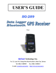
USER’S GUIDE
T-368
Data Logger
Bluetooth GPS Receiver
V1.0
ProGin Technology Inc.
10F-1,No.77,Sec.2,Chung-Hwa E.Rd.,East District, Tainan City701, Taiwan
Tel:+886-6-2694857 Fax:+886-6-2690442
E-mail: [email protected]
http://www.progin.com.tw
Contents
1. Introduction......................................................................................................................2
1.1 Overview...........................................................................................................................2
1. 2 Features..............................................................................................................................2
1.3 Electrical Characteristics.............................................................................3
2. Hardware………………………………………………………………………………...4
2.1 Dimension…………………………………………………………………………..4
2.2 Accessories…………………………………………………………………………..4
2.3 Description………………………………………………………………………….5
3. Operation………………………………………………………………………………...10
3.1 Getting Start…………………………………………………………………………....10
3.2 GPS Viewer for Testing.................................................................................................11
3.3 Function…………………………………………………………………………………12
3.4 Navigation……………………………………………………………………………..12
4. Warranty………………………………………………………………………………..12
Appendix: Software Specification…………………………………………..13
Appendix: Time Zone Table………………………………………………………..22
T-368 User’s Guide v1.0
1
1. Introduction
1.1 Overview
The ProGin T-368 Data logger GPS Receiver with LCD Display and Bluetooth enhanced is a total
solution GPS receiver with Bluetooth, UART interface and built-in rechargeable battery for high
sensitivity to tracking signal.
The T-368 receiver incorporates a wireless Bluetooth radio module, a high sensitivity, high performance
SiRF StarⅢ chipset, and a rechargeable battery in a compact design. The SiRF StarⅢ chipset is with
extremely high sensitivity for GPS signal acquisition and tracking. This Bluetooth GPS receiver allows
you to receive GPS data on mobile hand-held devices. By sending the GPS data wirelessly, you may
place this receiver on a position with best signal reception without the constraint of annoying wires. The
receiver is equipped with a portable, rechargeable, with removable battery, just like a mobile phone. The
only requirement is your corresponding hand-held device is also with the Bluetooth connection capability.
The receiver is very suitable for broad applications such as vehicle navigation, mapping, surveying,
security, agriculture, etc. Only a clear view of sky and a battery power are necessary to the unit. With its
low power consumption, the receiver tracks up to 20 satellites at a time while offering fast time-to-firstfix, re-acquires satellite signals less than 1 second (average) and updates position data every second.
1.2 Features
The T-368 provides a host of features that make it easy for integration and use.
1. With SiRF StarⅢ high sensitivity chipset.
2. High sensitivity and high performance receiver tracks up to 20 satellites.
3. High speed signal acquisition using 200,000 time/frequency search channels.
4. Built-in WAAS/EGNOS demodulator without additional hardware.
5. With the highly sensitive software to get the fast acquisition and reacquisition in the urban, canyon
and foliage environments.
6.
7.
8.
9.
Equipped with Li-ion rechargeable battery for long operating hours.
Over temperature protection for the battery.
Compatible with Bluetooth devices with Serial Port Profile (SPP).
Built-in high gain antenna.
10. Three LEDs show Bluetooth, GPS, and battery status.
11. LCD Display shows time, longitude, latitude, elevation, etc.
12. SD card supported for data storage in text file.
13. Supports standard NMEA-0183 data protocol and SiRF binary code at 19200 baudrate.
14. Built-in rechargeable battery for memory and RTC backup and for fast TTFF.
15. Flash-based program memory, new software revisions upgradeable through serial interface.
16. Compact and sleek design ideal for portable applications.
T-368 User’s Guide v1.0
2
1.3 Electrical Characteristics
General
Frequency
C/A code
Channels
Antenna
Sensitivity
Tracking
Accuracy
Position
L1, 1575.42 MHz
1.023 MHz chip rate
20 channels all in view tracking
internal
-159 dBm typical
Time
< 10 meters, 2D RMS
< 7 meters 2D RMS, WAAS corrected
1-5 meters, DGPS corrected
1 microsecond synchronized to GPS time
Default
WGS-84
Datum
Acquisition Rate (Open Sky)
Hot start
Warm start
Cold start
Reacquisition
1 sec, average
38 sec, average
42 sec, average
0.1 sec, average
Dynamic Conditions
Protocol message
NMEA-0183
Default NMEA
Altitude
Velocity
Acceleration
Jerk
GPS protocol
< 18,000 meters (60,000 feet)
< 515 meters/sec (1,000 knots)
<4G
20 meters/sec max
GGA, GSA, GSV, RMC, 19200 baudrate, (GLL, VTG, and
ZDA optional)
8 bits data, 1 stop bit, no parity.
Bluetooth Characteristics
BT Compliant
RF Tx Power
Receiver sensitivity
Communication distance
Communication profile
Version1.1
Class 2 (4 dBm max)
-80 dBm with BER<0.1%
10 meter typically
Serial Port Profile (SPP)
Power Consumption
Main power input
Operation Current
5.0 ± 5% VDC input
75 mA average in normal mode
T-368 User’s Guide v1.0
3
Battery
Source
Charging time
Operation time
Rechargeable and removable 1200 mAh Lithium-ion battery
with 5V DC input charging circuit
Fully charged 2.5 hours typical
12 hours after fully charged in continuous tracking mode
Environmental Characteristics
Operating temperature range
Storage temperature range
Charging temperature range
Operating humidity:
-10 oC to +60 oC
-20 oC to +70 oC
0 oC to +45 oC
5% to 95%, no condensing
Dimension
97.6 mm (L) x 45.8 mm (W) x 23.5 mm (H)
Weight
<70 g
(Battery & SD Card not included)
2. Hardware
2.1 Dimension
The receiver enclosure is with the dimension: 97.6 mm (L) x 45.8 mm (W) x 23.5 mm (H)
2.2 Accessories
1,
2,
3,
4,
5,
A 1200 mAh Lithium-ion rechargeable battery.
A vehicle lighter adapter assembly for battery recharge.
A household power adaptor assembly for battery recharge.
A USB cable assembly with “A” plug to mini USB plug.
User manual and CD.
T-368 User’s Guide v1.0
4
2.3 Description
1,
Body of the Bluetooth GPS unit is as shown in the figure.
There are three LED windows on the front cover to indicate the GPS, Bluetooth and battery
status. One LCD display panel on the front cover shows time, longitude, latitude, height,
speed, battery status, SD/MMC Card, and satellite signal status. Detailed LED and LCD
indications are described in next paragraph. The battery on/off switch and MMCX connector is
located on the same broadside of the body. There is a SD/MMC card slot located on the other
broadside of the body. The mini USB port for charging the battery is on the down side of the
body.
2,
LED status
T-368 User’s Guide v1.0
5
Remark: Battery charging suspended (protection when charging overtime or battery overheat)
Unplug the power plug and wait for a moment to resume charging.
3,
LCD Indication
The LCD display panel shows the following message:
T-368 User’s Guide v1.0
6
Please put a SD/MMC card in the slot before turning on the device.
The SD/MMC card should be formatted to FAT file system.
4, Bluetooth/Backlight usage (The default of Bluetooth/Backlight is ON.)
1.Under normal operation status, press button “A” for 1 second and then release to turn
off/on Backlight.
2.Under normal operation status, press button “B” for 1 second and then release to turn
off/on Bluetooth.
Under Recorder USER mode, the Bluetooth ON/OFF setting function will be
disabled. If you want to turn on/off Bluetooth under USER mode, please use
Bluetooth setup described in 5. Display Setup below.
5,
Display Setup (Please refer to Appendix: Time Zone Table for time zone adjustment.)
1. Press button “A” for 2 seconds then release to enter into setup menu.
2. Press “Select” for 1 second to increase the parameter figure.
3. Press “Next” for 1 second to select different parameters.
4. After finishing setup, press “Exit” for 1 second to back to operation status.
Whenever setting up, the power of the device must be turned off then on again to
reactivate the signal.
T-368 User’s Guide v1.0
7
6,
SD/MMC Recorder Setup (The default of Recorder is AUTO.)
1.
2.
3.
4.
Press Button “B” for 2 seconds then release to enter SD/MMC recorder setup function
Press “Select” for 1 second to increase the parameter figure.
Press “Next” for 1 second to select different parameters.
Under USER mode, the Bluetooth ON/OFF setting function will be disabled. Press button
“B” for 1 second to record, recording once per press button.
5. Under AUTO mode, the recording is as follows:
Speed
0 Km/h
Under 10 Km/h
Under 40 Km/h
Under 70 Km/h
Under 100 Km/h
Over 100 Km/h
Record
No record
Record once per 2 seconds
Record once per 5 seconds
Record once per 8 seconds
Record once per 10 seconds
Record once per 20 seconds
Whenever setting up, the power of the device must be turned off then on again to
reactivate the signal.
T-368 User’s Guide
v1.0
8
T-368 User’s Guide v1.0
9
3. Operation
3.1 Getting Start
Step 1: Battery Installation
(a) Slide the power switch to “OFF” position.
(b) Press the “PUSH” button then slide the bottom cover off.
(c) Insert the Li-ion battery into the compartment. Note the orientation of the battery.
(d) Slide the bottom cover back to locked condition.
Step 2: Charge
Please charge the battery to full capacity when first time to use.
Connect the attached adaptor cord to the
mini USB jack, as shown in the following figure.
The battery indication is with dual-color LEDs. The green LED will be on until charge completes.
The LED indication for the battery status is described in the following.
Battery low ----------------------------------------------------------------- Red LED flashing
Battery in charging -------------------------------------------------------- Green LED steady on
Battery charging suspended (protection when
charge timer over or battery overheat) ----------------- Green LED flashing
Charge completes or battery in normal capacity ---------------------- both LEDs off
T-368 User’s Guide v1.0
10
Step 3: GPS acquisition
Turn the power switch “on.” The slide switch is on the broadside of the body.
on, both the Bluetooth and GPS indication LEDs start to flash.
Once the power is turned
Take the Bluetooth GPS to places with clear view of the sky. The Red LED indicates the status.
(a) LED steady on when power is connected and for the initial acquisition process;
(b) LED flashes at 1 second on and 1 second off when the receiver outputs position fix data.
Step 4: Wireless Link
Turn on the host device, a PDA or a NB with Bluetooth function. Then execute Bluetooth manager
program to perform “search” and “pair” procedures. The default PIN code is “0000” for host devices to
access this BT GPS unit (in paired mode).
The Blue LED indicates following Bluetooth radio status.
(a) LED flashes at 3 seconds interval for standby mode;
(b) LED flashes at 0.2 second interval for pairable mode;
(c) LED flashes at 1 second interval if there is an active RF link.
3.2 GPS Viewer for Testing
Install a GPS Viewer program to host device. You may check the status of the GPS receiver whenever you
like to. Following are standard buttons and operation steps.
(a) Execute the Viewer program. Press the “Com Port:” button to set “Com Port” for this data link and
the “Baudrate” to any one of 2400, 4800, 9600, 19200, 38400…
(b) Click “Start” to receive data. Usually a window shows the NMEA format data stream while another
window shows tracked satellites signal quality.
(c) Once the link is successful, click “Stop” button to stop the program. However, you may click, for
example, the “Cold Start” button to perform “cold start” testing.
T-368 User’s Guide v1.0
11
3.3 Function
As soon as the power on, the T-368 Bluetooth GPS receiver begins the process of satellite acquisition,
tracking, and Bluetooth radio connection. Under normal circumstances, it takes around 42 seconds
(average) to achieve a position fix at the first time. After a position fix has been calculated, information
about valid position, velocity, and time is transmitted over the output channel. The T-368 Bluetooth GPS
receiver utilizes initial data, such as last stored position, date, time and satellite orbital data, to achieve
maximum acquisition performance. If significant inaccuracy exists in the initial data or the orbital data is
obsolete, it may take more time to achieve a navigation solution.
3.4 Navigation
After the acquisition process is complete, the T-368 Bluetooth GPS receiver sends valid navigation
information over output channels. These data include:
1) Latitude/longitude/altitude
2) Velocity
3) Date/time
4) Error estimates
5) Satellite and receiver status
4. Warranty
The GPS smart receiver is warranted to be free from defects in material and functions for one year from the
date of purchase. Any failure of this product within this period under normal conditions will be replaced at
no charge to the customers.
T-368 User’s Guide v1.0
12
Appendix: Software Specifications
NMEA Protocol
The T-368 interface protocol is based on the National Marine Electronics Association (NMEA)
interface specification, namely, the NMEA 0183 standard. The T-368 is capable of supporting the
following NMEA message formats specifically developed and defined by SiRF.
NMEA Message Prefix
Format
Direction
$GPGGA
Time, position and fix type data.
Out
$GPGLL
Latitude, longitude, time of position fix and status.
Out
$GPGSA
GNSS DOP and active satellites
Out
$GPGSV
Satellites in view.
Out
$GPMSS
Radio beacon signal-to-noise ratio, signal strength,
frequency, etc.
Out
$GPRMC
Recommended minimum specific GNSS data.
Out
$GPVTG
Speed and course over ground.
Out
$GPZDA
Date and time.
Out
General NMEA Format
The general NMEA format consists of an ASCII string commencing with a ‘$’ character and
terminating with a <CR><LF> sequence. NMEA standard messages commence with ‘GP’ then a
3-letter message identifier. The message header is followed by a comma delimited list of fields
optionally terminated with a checksum consisting of an asterix ‘*’ and a 2 digit hex value representing
the checksum. There is no comma preceding the checksum field. When present, the checksum is
calculated as a bitwise exclusive of the characters between the ‘$’ and ‘*’. As an ASCII
representation, the number of digits in each number will vary depending on the number and precision,
hence the record length will vary. Certain fields may be omitted if they are not used, in which case
the field position is reserved using commas to ensure correct interpretation of subsequent fields.
T-368 User’s Guide v1.0
13
$GPGGA
This message transfers global positioning system fix data.
Following is an example.
$GPGGA,161229.487,3723.2475,N,12158.3416,W,1,07,1.0,9.0,M, , , ,0000*18
The $GPGGA message structure is shown below:
Field
Example
Unit
Notes
Message ID
$GPGGA
GGA protocol header.
UTC Time
161229.487
hhmmss.sss
Latitude
3723.2475
ddmm.mmmm
N/S Indicator
N
N=north or S=south.
Longitude
12158.3416
dddmm.mmmm
E/W indicator
W
E=east or W=west.
Position Fix Indictor
1
0: Fix not available or invalid.
1: GPS SPS mode, fix valid.
2: Differ. GPS, SPS mode, fix valid
3-5: Not supported.
6: Dead Reckoning Mode, fix valid. (1)
Satellites Used
07
Number of satellites used to calculate fix.
Range 0 to 12.
HDOP
MSL Altitude
1.0
(2)
Units
Geoid Separation
Horizontal Dilution of Precision.
9.0
Meter
Altitude above mean seal level.
M
Meter
M stands for “meters”.
Meter
Separation from Geoids can be blank.
Meter
Second
M stands for “meters”.
Age in seconds. Blank (Null) fields when
DGPS is not used.
(2)
Units
Age of Diff. Corr.
Diff Ref. Station ID
0000
Checksum
*18
<CR> <LF>
Message terminator.
(1)
Only apply to NMEA version 2.3 (and later) in this NMEA message description.
(2)
SiRF does not support geoid corrections. Values are WGS84 ellipsoid heights.
T-368 User’s Guide v1.0
14
$GPGLL
This message transfers geographic position, latitude, longitude, and time. Following is an example.
$GPGLL,3723.2475,N,12158.3416,W,161229.487,A,A*41
The $GPGLL message structure is shown below:
Field
Example
Unit
Message ID
$GPGLL
GLL protocol header.
Latitude
3723.2475
ddmm.mmmm
N/S Indicator
N
N=north or S=south.
Longitude
12158.3416
dddmm.mmmm
E/W indicator
W
E=east or W=west.
UTC Time
161229.487
hhmmss.sss
Status
A
A: Data valid or V: Data invalid.
Mode
A
A=Autonomous, D=DGPS, E=DR
(Only present in NMEA version 3.00).
Checksum
*41
<CR><LF>
Notes
Message terminator.
T-368 User’s Guide v1.0
15
$GPGSA
This message transfers DOP and active satellites information. Following is an example.
$GPGSA,A,3,07,02,26,27,09,04,15, , , , , ,1.8,1.0,1.5*33
The $GPGSA message structure is shown below:
Field
Example
Message ID
$GPGSA
Unit
Notes
GSA protocol header.
Mode A
M: Manual, forced to operate in selected 2D
or 3D mode.
A: Automatic switching between modes.
Mode 3
1
2
3
Fix not available.
2D position fix.
3D position fix.
Satellites Used (1)
07
SV on channel 1.
Satellites Used (1)
02
SV on channel 2.
…
..
Satellites Used
(1)
SV on channel 12.
PDOP
1.8
HDOP
1.0
VDOP
1.5
Checksum
*33
<CR> <LF>
(1)
Message terminator.
Satellites used in solution.
T-368 User’s Guide v1.0
16
$GPGSV
This message transfers information about satellites in view. The $GPGSV message structure is shown
below. Each record contains the information for up to 4 channels, allowing up to 12 satellites in view.
In the final record of the sequence the unused channel fields are left blank with commas to indicate that
a field has been omitted. Following is an example.
$GPGSV,2,1,07,07,79,048,42,02,51,062,43,26,36,256,42,27,27,138,42*71
$GPGSV,2,2,07,09,23,313,42,04,19,159,41,15,12,041,42*41
The $GPGSV message structure is shown below:
Field
Example
Unit
Notes
Message ID
$GPGSV
GSA protocol header.
Number of messages (1)
2
Number of messages, maximum 3.
Message number
1
Sequence number, range 1 to 3.
Satellites in view
07
Number of satellites currently in view.
Satellite ID
07
Channel 1, ID range 1 to 32.
Elevation
79
degree
Elevation of satellite, maximum 90.
Azimuth
048
degree
Azimuth of satellite, range 0 to 359.
SNR (C/N0)
42
dBHz
Range 0 to 99, null when not tracking.
Satellite ID
02
Elevation
51
degree
Elevation of satellite, maximum 90.
Azimuth
062
degree
Azimuth of satellite, range 0 to 359.
SNR (C/N0)
43
dBHz
Range 0 to 99, null when not tracking.
Satellite ID
26
Elevation
36
degree
Elevation of satellite, maximum 90.
Azimuth
256
degree
Azimuth of satellite, range 0 to 359.
SNR (C/N0)
42
dBHz
Range 0 to 99, null when not tracking.
Satellite ID
27
Elevation
27
degree
Elevation of satellite, maximum 90.
Azimuth
138
degree
Azimuth of satellite, range 0 to 359.
SNR (C/N0)
42
dBHz
Range 0 to 99, null when not tracking.
Checksum
*71
Channel 2, ID range 1 to 32.
Channel 3, ID range 1 to 32.
Channel 4, ID range 1 to 32.
<CR> <LF>
Message terminator.
(1) Depending on the number of satellites tracked multiple messages of GSV data may be required.
T-368 User’s Guide v1.0
17
$GPMSS
This message transfers information about radio beacon signal-to-noise ratio, signal strength, frequency,
etc. Following is an example.
$GPMSS,55,27,318.0,100,1,*57
The $GPMSS message format is shown below.
Field
Example
Unit
Notes
Message ID
$GPMSS
Signal Strength
55
Signal-to-Noise Ratio
27
Beacon Frequency
318.0
Beacon Bit Rate
100
Bits per second.
Channel Number (1)
1
The channel of the beacon being used if a
multi-channel beacon receiver is used.
Checksum
*57
MSS protocol header.
dB
SS of tracked frequency.
dB
kHz
<CR> <LF>
SNR of tracked frequency.
Currently tracked frequency.
Message terminator.
(1) Fields marked in italic red apply only to NMEA version 2.3 (and later) in this NMEA message description.
T-368 User’s Guide v1.0
18
$GPRMC
This message transfers recommended minimum specific GNSS data. Following is an example.
$GPRMC,161229.487,A,3723.2475,N,12158.3416,W,0.13,309.62,120598, ,*10
The $GPRMC message format is shown below.
Field
Example
Message ID
$GPRMC
RMC protocol header.
UTC Time
161229.487
hhmmss.sss
Status
A
A: Data valid or V: Data invalid.
Latitude
3723.2475
ddmm.mmmm
N/S Indicator
N
N=north or S=south.
Longitude
12158.3416
ddmm.mmmm
E/W indicator
W
E=east or W=west.
Speed over ground
0.13
knot
Speed over ground
Course over ground
309.62
degree
Course over ground
Date
120598
Magnetic variation (1)
Unit
ddmmyy, current date.
degree
Mode (2)
A
Checksum
*10
Notes
Not used.
A=Autonomous, D=DGPS, E=DR.
<CR> <LF>
Message terminator.
(1)
SiRF does not support magnetic declination. All “course over ground” data are geodetic WGS84 directions.
(2)
Fields marked in italic red apply only to NMEA version 2.3 (and later) in this NMEA message description.
T-368 User’s Guide v1.0
19
$GPVTG
This message transfers velocity, course over ground, and ground speed. Following is an example.
$GPVTG,309.62,T, ,M,0.13,N,0.2,K,A*23
The $GPVTG message format is shown below.
Field
Example
Message ID
$GPVTG
Course (true)
309.62
Reference
T
Course (magnetic)
Unit
Notes
VTG protocol header.
degree
Measured heading
T = true heading
degree
Measured heading
Reference (1)
M
M = magnetic heading (1)
Speed
0.13
Units
N
Speed
0.2
Units
K
K = km/hour.
Mode (2)
A
A=Autonomous, D=DGPS, E=DR.
Checksum
*23
knot
Speed in knots
N = knots
km/hr
<CR> <LF>
Speed
Message terminator.
(1)
SiRF does not support magnetic declination. All “course over ground” data are geodetic WGS84 directions.
(2)
Fields marked in italic red apply only to NMEA version 2.3 (and later) in this NMEA message description.
T-368 User’s Guide v1.0
20
$GPZDA
This message transfers UTC Time and Date.
Following is an example.
$GPZDA,181813,14,10,2003,00,00*4F
The $GPZDA message format is shown below.
Field
Example
Unit
Message ID
$GPZDA
ZDA protocol header.
UTC Time
181813
Either using valid IONO/UTC or estimated
from default leap seconds.
UTC Day
14
01 to 31, day of month.
UTC Month
10
01 to 12.
UTC Year
2003
1980 to 2079.
Local zone hours
00
Offset from UTC (set to 00).
Local zone minutes
00
Offset from UTC (set to 00).
Checksum
*4F
<CR> <LF>
Notes
Message terminator.
T-368 User’s Guide v1.0
21
Appendix: Time Zone Table
Coordinated
Universal Time
Time Zone Name
Daylight Saving
Time
Eniwetok, Kwajalein
-12
Midway Island, Samoa
-11
-
Hawaii
-10
-
Alaska
-9
-8
Pacific Time (US and Canada); Tajuana
-8
-7
Mountain Time (US and Canada), Chihuahua, La Paz,
Mazatlan, Arizona
-7
-6
Central Time (US and Canada), Saskatchewan,
Guadalajara, Mexico City, Monterrey, Central America
-6
-5
-5
-41
Eastern Time (US and Canada), Indiana (East), Bogota,
Lima, Quito
Atlantic Time (Canada), Caracas, La Paz, Santiago
Newfoundland
-4
-3.5
-2.5
Brasilia, Buenos Aires, Georgetown, Greenland
-3
Mid-Atlantic
-2
Azores, Cape Verde Islands
-1
Greenwich Mean Time: Dublin, Edinburgh, Lisbon,
London, Casablanca, Monrovia
+0
+1
Amsterdam, Belgrade, Bratislava, Budapest, Ljubljana,
Prague, Sarajevo, Skopje, Warsaw, Zagreb, Brussels,
Copenhagen, Madrid, Paris, Berlin, Bern, Rome,
Stockholm, Vienna, West Central Africa
+1
+2
Athens, Istanbul, Minsk
+2
+3
Bucharest, Cairo, Pretoria, Jerusalem, Harare, Pretoria
+2
+3
Helsinki, Riga, Israel, Kyiv, Sofia, Tallinn, Vilnius
+2
+3
Baghdad, Kuwait, Riyadh, Nairobi
+3
+4
Moscow, St. Petersburg, Volgograd
+3
+4
+3.5
+4.5
Tehran
T-368 User’s Guide v1.0
22
Coordinated
Universal Time
Daylight Saving
Time
+4
-
+4.5
-
+5
-
+5.5
-
+6
-
+7
-
+8
-
+8
-
Osaka, Sapporo, Tokyo
+9
-
Seoul, Yakutks
+9
-
Adelaide, Darwin
+9.5
-
Brisbane, Guam, Port Moresby
+10
-
Canberra, Melbourne, Sydney
+10
-
Hobart, Vladivostok
+10
-
Magadan, Solomon Islands, New Caledonia
+11
+12
Auckland, Wellington
+12
-
Fiji Islands, Kamchatka, Marshall Islands
+12
-
Time Zone Name
Abu Dhabi, Muscat, Baku, Tbilisi, Yerevan
Kabul
Ekaterinburg, Islamabad, Karachi, Tashkent
Bombay, Calcutta, Madras, New Delhi, Chennai, Kolkata
Almaty, Dhaka, Colombo, Astana, Sri Jayawardenepura,
Novosibirsk
Bangkok, Hanoi, Jakarta, Krasnoyarsk
Beijing, Changqing, Hong Kong, Uramqi
Perth, Singapore, Taipei, Beijing, Chongqing, Hong Kong
SAR, Kuala Lumpur, Irkutsk, Ulaan Bataa
*Unit: hour
All Rights Reserved
T-368 User’s Guide v1.0
23