1
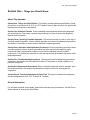
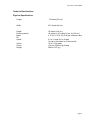
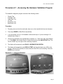
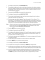
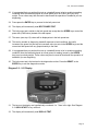
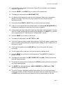
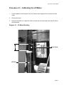
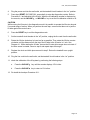
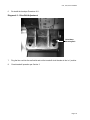
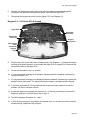
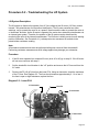
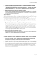
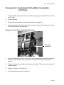
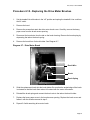
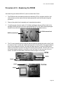
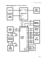
9.31, 9.33, 9.35 Treadmill
9.31, 9.33, 9.35 Treadmill
Warning: This service manual is for use by Precor trained service providers only.
If you are not a Precor Trained Servicer, you must not attempt to service any Precor Product;
Call your dealer for service.
This document contains information required to perform the majority of troubleshooting, and
replacement procedures required to repair and maintain this product.
This document contains general product information, software diagnostic procedures (when
available), preventative maintenance procedures, inspection and adjustment procedures,
troubleshooting procedures, replacement procedures and electrical block and wiring diagrams.
To move directly to a procedure, click the appropriate procedure in the bookmark section to the
left of this page. You may “drag” the separator bar between this page and the bookmark section
to change the size of the page being viewed.
© 2003 Precor Incorporated
Unauthorized Reproduction and Distribution Prohibited By Law
Page 1
9.31, 9.33, 9.35 Treadmill
Section One - Things you Should Know
About This Appendix
Section One, Things You Should Know. This section includes technical specifications. Read
this section, as well as the 9.31, 9.33 or 9.35 Treadmill Owner’s Manual, before you perform the
maintenance procedures in this manual.
Section Two, Software Features. Precor treadmills are programmed with several diagnostic
and setup features. This section contains the procedures you need to access the diagnostic
features on this treadmill.
Section Three, Checking Treadmill Operation. This section provides you with a quick way of
checking treadmill operation. Check treadmill operation at the end of a maintenance procedure
and when it is necessary to ensure that the treadmill is operating properly.
Section Four, Inspection and Adjustment Procedures. Perform inspection procedures when
a trouble symptom points to a particular problem and after removing and replacing major
components. Many maintenance problems can be fixed by adjusting various treadmill
components. This section also provides you with the step-by-step procedures required to make
these adjustments.
Section Five, Troubleshooting Procedures. The diagnostic and troubleshooting procedures
contained in this section should be performed when it is necessary to isolate a problem to a
particular component.
Section Six, Replacement Procedures. When a treadmill component must be replaced, go to
this section and follow the step-by-step procedures required to remove and replace the
component.
Section Seven, Technical Diagrams and Parts Lists. This section includes wiring diagrams,
and block diagrams for the 9.31, 9.33 and 9.35 Treadmill.
General Information
For the latest exploded view diagram, part number and part pricing information, visit the Precor
dealer website at “www.precor.com/Dealer”.
Page 2
9.31, 9.33, 9.35 Treadmill
Technical Specifications
Physical Specifications
Length:
79 inches (201 cm.)
Width:
33.5 inches (85 cm.)
Height:
Running surface:
Motor:
DC
Speed:
55 inches (140 cm.)
20 inches by 57 inches (51 cm. by 145 cm.)
2.75 (9.31, 9.33), 3.0 (9.35) hp. continuous duty
Incline:
Power:
Weight:
0.5 to 11 mph (0.8 to 18 kph)
10 mph is equivalent to a 6 minute mile
0% to +15% grade
120 Vac 50/60 Hz @ 20 amp
280 lbs (127 kg.)
Page 3
9.31, 9.33, 9.35 Treadmill
Procedure 2.1 - Accessing the Hardware Validation Program
The treadmill's diagnostic program consists of the following modes:
•
•
•
•
•
•
Display Test
Keyboard Test
Heart Rate Test
Lift Test
Belt Speed Test
Belt Power Test
Procedure
1.
Plug the power cord into the wall outlet, then turn on the treadmill with the circuit breaker.
2.
Press keys RESET,5,1,7,6,5,7,6,1, sequentially.
3.
If you are testing a 9.33 or 9.35 treadmill continue with step 4. If you are testing a 9.31
treadmill skip to step 31.
4.
The keys on the display are hypothetically numbered 1 to 7 from left to right. See Diagram
2.1. The STOP is key number 4 and is located directly below the QUICK START key. The
QUICK START key is not part of the numbering sequence.
5.
The display will momentarily read DIAGS - HARDWARE VALIDATION.
6.
The display will momentarily read DISPLAY TEST and then illuminate every LED on the
display. Check all LED positions to ensure that all of the LED’s are functioning. Press the
ENTER key to continue.
Diagram 2.1 - 9.33 & 9.35 Displays
Page 4
9.31, 9.33, 9.35 Treadmill
7.
The display will momentarily read KEYBOARD TEST.
8.
The keyboard test will place two dots on the display for each key on the display, including
the numeric keypad. Pressing a key will cause the upper of the two dots associated with the
key to go out. Test all of the keys in this manner. Tug on the safety key lanyard, to ensure
that the STOP key is activated.
9.
Press and hold the ENTER key to proceed to the heart rate test.
10. The display will momentarily read HEART RATE TEST.
11. The heart rate test will display the heart rate being received during this test from either a
chest strap transmitter or test transmitter.
12. Three heart rate values will be displayed. They will be prefixed “U” for unfiltered, “F” for
filtered and “P” for Polar filtering. The Polar filtered heart rate will also appear in the normal
heart rate display, since Polar filtering is the filtering used during normal operation. The right
most red LED in the smart rate display will flash each time a heart beat is detected.
Note:
If there is not a heart rate receiver installed or there is a bad or intermittent connection
between the heart rate receiver and the upper PCA, the messages in step 9 will be
replaced by the message NO HEART RATE RECEIVER.
13. Press the ENTER key to proceed to the lift test.
14. The display will momentarily read LIFT TEST.
15. Two numbers will be displayed, the percent of lift and A/D number related to the current lift
position. The A/D (analog to digital) number represents the lift potentiometer reading. The
A/D number will be in the range of 0 to 255.
16. The lift may be operated using the INCLINE keys. The incline percentage and A/D numbers
will change accordingly.
17. The A/D reading will be used later in this service manual to calibrate the lift.
18. Press the ENTER key to proceed to the belt speed test.
19. The display will momentarily read BELT SPEED TEST.
20. The speed of the running belt is controlled by the SPEED keys during this test.
21. The following values are displayed; time (that the running belt has operated during this test),
current (in amps through the drive motor), belt speed (in MPH) and power bits (PWM value).
22. This test is valuable in diagnosing treadmill load conditions such as running bed and/or
running belt condition. As load is increased, the speed is kept at a constant value (as set via
the SPEED keys) and the current and power bits will vary proportionately to the load.
Page 5
9.31, 9.33, 9.35 Treadmill
23. It is suggested that you perform this test on a treadmill known to be in excellent operating
condition. Note the values displayed at a fixed speed (such as 3 MPH) and your body
weight. Those values may then be used to benchmark the operation of treadmills you are
diagnosing.
24. Press press the ENTER key to proceed to the belt power test.
25. The display will momentarily read BELT POWER TEST.
26. The belt power test is similar to the belt speed test except that the SPEED keys control the
power bits (PWM value) instead of the belt speed.
27. The same (see step 16) values will be displayed as in the belt speed test.
28. This test is valuable in diagnosing treadmill response to load conditions. As load is
increased, the power bits are kept at a constant value (as set via the SPEED keys) and the
current and belt speed will vary proportionately to the load.
29. It is suggested that you perform this test on a treadmill known to be in excellent operating
condition. Note the values displayed at a fixed power bit reading (as set by the SPEED
keys) and your body weight. Those values may then be used to benchmark the operation of
treadmills you are diagnosing.
30. The belt power test is the last test in the diagnostics routine. Press the RESET or the
ENTER key to exit the diagnostics routine.
Diagram 2.2 - 9.31 Display
31. The keys on the display are hypothetically numbered 1 to 7 from left to right. See Diagram
2.2. QUICK START is key number 4.
32. The display will momentarily read DISPLAY TEST.
Page 6
9.31, 9.33, 9.35 Treadmill
33. All of the LED’s on the display will illuminate. If any LED on the display is not illuminated,
replace the upper PCA.
34. Press the SELECT or the RESET key to continue to the keyboard test.
35. The display will momentarily read KEYBOARD TEST.
36. An indicator will be displayed for each key on the keyboard. When a key is pressed the
indicator will change. Press every key on the keyboard to ensure that all keys are
functioning normally.
37. Press and hold the RESET or SELECT key to continue to the heart rate test.
38. If the 9.31 is not equipped with the heart rate option, the message NO HR RECEIVER will
be displayed indicating that a heart rate receiver was not detected.
39. Create a heart rate signal using either a heart rate chest strap or test transmitter. The heart
rate LED will flash and the heart rate reading will be displayed. The SELECT key will allow
you to toggle between P - Polar filtering, U - unfiltered and F - filtered.
40. Press the RESET key to continue to the lift test.
41. The display will momentarily read LIFT TEST then A/D.
42. The lift A/D (analog to digital) number will be displayed. The lift A/D number is related to the
current lift position and represents the lift potentiometer reading. The A/D number will be in
the range of 0 to 255.
43. The lift may be operated using the INCLINE keys. The lift A/D number will change
accordingly.
44. The A/D reading will be used later in this service manual to calibrate the lift.
45. Press the RESET key to proceed to the belt speed test. Press SELECT to display the
percent of incline.
46. The display will momentarily read BELT SPEED TEST then MPH. The display then show
the actual operating speed.
47. The speed of the running belt is controlled by the SPEED keys during this test as it would be
in a normal operating mode.
48. The SELECT key will toggle between a MPH, POWERBITS and TIME display. TIME
indicates the test’s elapsed time.
49. This test is valuable in diagnosing treadmill load conditions such as running bed and/or
running belt condition. As load is increased, the speed is kept at a constant value (as set via
the SPEED keys) and the current and power bits will vary proportionately to the load.
Page 7
9.31, 9.33, 9.35 Treadmill
50. It is suggested that you perform this test on a treadmill known to be in excellent operating
condition. Note the values displayed at a fixed speed (such as 3 MPH) and your body
weight. Those values may then be used to benchmark the operation of treadmills you are
diagnosing.
51. Press press the RESET key to proceed to the belt power test.
52. The display will momentarily read BELT POWER TEST then POWERBITS. The display will
then read the current powerbit value.
53. In this test SPEED keys control the power bit setting instate of the actual speed.
54. The SELECT key will toggle between a MPH, POWERBITS and TIME display. TIME
indicates the test’s elapsed time.This test is valuable in diagnosing treadmill response to
load conditions. As load is increased, the power bits are kept at a constant value (as set via
the SPEED keys) and the current and belt speed will vary proportionately to the load.
55. It is suggested that you perform this test on a treadmill known to be in excellent operating
condition. Note the values displayed at a fixed power bit reading (as set by the SPEED
keys) and your body weight. Those values may then be used to benchmark the operation of
treadmills you are diagnosing.
56. The belt power test is the last test in the diagnostics routine. Press the RESET key to exit
the diagnostics routine.
Page 8
9.31, 9.33, 9.35 Treadmill
Procedure 2.2 - Accessing the Information Display Program
The information display will access the following data;
•
•
•
•
Odometer
Hour meter
Software version
Error log
Procedure
1.
Plug the power cord into the wall outlet, then turn on the treadmill with the circuit breaker.
2.
Press the keys RESET,6,5, sequentially.
3.
If you are testing a 9.33 or 9.35 treadmill continue with step 4. If you are testing a 9.31
treadmill skip to step 19.
4.
The display will momentarily read, DIAGS - INFORMATION DISPLAY.
5.
The display will momentarily read, ODOMETER.
6.
The treadmill’s odometer will be displayed as 1234567 MPH or 1234567 KPH.
Note:
The odometer data is stored in non-volatile memory on the upper PCA. If the upper PCA
is replaced the odometer data will be lost.
7.
Press the ENTER key to proceed to the hour meter display.'
8.
The display will momentarily read, HOUR METER.
9.
The operating time of the unit will be displayed as 12345 HOURS. The operating time is
defined as total amount of time that the unit has operated in program modes with the drive
motor running. The hour meter is also used to provide the “time stamp” for the error code
log.
10. Press the ENTER key to proceed to the software version display.
11. The display will momentarily read, SOFTWARE VERSION.
12. The software versions of the upper and lower PCA’s will be displayed as;
UPPER 1.01
LOWER 1.01.
13. Press the ENTER key to proceed to the error log.
Page 9
9.31, 9.33, 9.35 Treadmill
14. The error log will store up to 10 error conditions. The errors are logged with the most recent
error in position one. When a new error condition occurs, each existing error is pushed down
one position in log. If there was an error in position 10 when a new error was logged, the
error that was in position 10 will be lost.
15. Each error in the log will show the odometer reading (in miles) and the time (hour meter)
when the error occurred. The errors are displayed as;
1
ER20
1234567 MI
12345 HRS.
16. The arrows keys will allow you to scroll through the log. When the first unused position is
reached in the log, the message NO MORE ERRORS will be displayed.
17. When the QUICK START key is held for 2 seconds the message HOLD TO CLEAR
ERRORS will be displayed. If the QUICK START key is held for an additional 2 seconds, the
message CLEARED will be displayed. When the QUICK START key is released the
message NO MORE ERRORS will be displayed and all error are erased from the log.
18. Press the RESET the ENTER key to exit the information display.
19. The display will scroll either MILES: 1234567 or KILOMETERS 1234567. The reading will
indicate the total distance that has been recorded on the treadmill.
20. Press the SELECT or RESET key to continue to the hours display.
21. The display will read HOURS: 1234. The reading will indicate the total number of hours of
use.
22. Press the SELECT or RESET key to continue to the software version display.
23. The display will continuously toggle between UPPER SW VER X.XX. and LOWER SW VER
X.XX.
24. Press the SELECT or RESET key to continue to the error log display.
25. The first error log entry will scroll 1:ERR XX at 123456 MILES 12435 HOURS. If there are
no errors in the log, the message NO ERRORS will be scrolled.
26. The ▲ key will move through the log to older errors (if any). If there are no more errors, the
message NO MORE ERRORS will be scrolled.
27. Pressing and holding the QUICK START key for 2 seconds will cause the prompt CLEAR?
to be displayed, holding the QUICK START for an additional 2 seconds will clear all existing
entries from the error log. The display will confirm that the error log has been cleared by
displaying OK. The display will revert to the first log entry and show it as a null entry (1: ---).
If the QUICK START key is not held for a minimum of 4 seconds, the error log will not be
cleared.
28. Press the RESET or SELECT key to exit the information display program.
Page 10
9.31, 9.33, 9.35 Treadmill
Procedure 2.3 - Accessing the User Parameter Program
This procedure allows you to change the following settings:
•
•
•
Set Measurement Units
Enable/Disable Password
Set User Name
Procedure
1.
Plug the power cord into the wall outlet, then turn on the treadmill with the circuit breaker.
2.
Press keys RESET,5,6,7,1 sequentially.
3.
If you are testing a 9.33 or 9.35 treadmill continue with step 4. If you are testing a 9.31
treadmill skip to step 17.
4.
The display will momentarily read, DIAGS - SET USER PARAMETERS.
5.
The display will momentarily read SELECT UNITS
6.
The currently selected measurement unit will then be displayed.
7.
Use the
8.
Press the ENTER key to select the currently displayed measurement unit.
9.
The display will momentarily read, PASSWORD
10. Use the
,
,
keys to scroll through the available measurement units.
keys to select either PASSWORD ENABLED or PASSWORD DISABLED.
11. Press the ENTER key to exit diagnostics (9.33 only) or to continue to set user name (9.35
only).
12. The display will momentarily read, USER NAME.
13. Up to four user names may be entered. If user names have not been previously entered the
default user names will be USER1, USER2, USER3 and USER4.
14. The USER1 name will be displayed first. The ENTER key will select USER2, then USER3,
then USER4.
15. With the user name to be edited displayed, use the INCLINE , INCLINE , to select the
character position to be edited. Use the SPEED , SPEED keys to select the letter to be
placed in the selected character position. The user name can be a maximum of five
characters.
Page 11
9.31, 9.33, 9.35 Treadmill
16. Press the ENTER key to select the next user name or to exit the program.
17. The display will read SELECT UNITS: and scroll either US STANDARD or METRIC.
18. Use the
,
keys to select the desired measurement units.
19. Press the RESET or SELECT key to continue with password section.
20. The display will scroll PASSWORD: ENABLED or PASSWORD: DISABLED. Use the
keys to select the desired setting.
,
21. Press the RESET key to exit the user parameter program.
Page 12
9.31, 9.33, 9.35 Treadmill
Procedure 2.4 - Documenting Software Problems
When a problem is found with the software in the upper or lower PCA, record the information
listed below.
When a problem occurs, record the following information:
•
•
Model and serial number
Software version number
•
•
Program number running when the problem occurred
A description of:
•
a.
What happened or failed to happen.
b.
The action taken by the user just before the problem occurred.
c.
Problem-related information (such as how far into the program the problem occurred,
the work level being used when the problem occurred, etc.).
The frequency of occurrence.
Page 13
9.31, 9.33, 9.35 Treadmill
Section Three - Checking Treadmill Operation
This section provides you with a quick method of checking treadmill operation. Check treadmill
operation at the end of a maintenance procedure and when it is necessary to ensure that the
treadmill is operating properly.
Procedure
4.
Plug the power cord into the wall outlet, then turn on the treadmill with the circuit breaker.
5.
Place the treadmill in Manual Mode. Adjust the speed of the running belt to 2–3 m.p.h.
Operate the treadmill for at least 5 minutes.
a.
Concentrate on the feel of the running belt and the sound of the drive motor and rollers.
Be on the alert for unusual noises, smells, or vibrations.
b.
Log the power bits under loaded and unloaded conditions.
c.
Observe the LED’s on the electronic console. Make sure that each LED lights as the information corresponding to that LED is displayed on the electronic console.
3.
If during step 1c, squeaking noises associated with the running deck were heard, check the
lubrication of the running deck studs. If necessary, apply silicon grease to all of the running
deck studs.
3.
Press the STOP key. When the treadmill comes to a stop, view the electronic console as the
treadmill scans time, speed, distance and percent of lift.
4.
Press the INCLINE ▲ key while viewing the electronic console. Confirm that the running
bed inclines and the incline display increments to 15% as the INCLINE ▲ key is pressed.
5.
Press the INCLINE ▼ key while viewing the electronic console. Confirm that the running bed
returns to a level position and the incline display decrements to 0% as the INCLINE ▼ key is
pressed.
6.
Turn off the treadmill with the circuit breaker, then unplug the treadmill from the wall outlet.
Page 14
9.31, 9.33, 9.35 Treadmill
Procedure 4.1 - Calibrating the Lift Motor
1.
Set the treadmill circuit breaker in the “off” position and unplug the line cord from the wall
outlet.
2.
Remove the hood.
3.
Place the treadmill on it’s right side. Remove hitch and clevis pins that secure the lift tube to
the lift platform.
Diagram 4.1 - Lift Motor Mounting
1”
Drive Screw
Lift Tube
Page 15
9.31, 9.33, 9.35 Treadmill
4.
Plug the power cord into the wall outlet, set the treadmill circuit breaker in the “on” position.
5.
Press keys RESET, 5,1,7,6,5,7,6,1, sequentially to enter the diagnostics routine. Refer to
Procedure 2.1 and advance to the lift test. When the lift calibration number is displayed on
the console, use the INCLINE ▲ or INCLINE ▼ key to set the lift calibration number to 20.
CAUTION
While running the lift motor in the diagnostics mode it is possible to operate the lift motor beyond
it’s normal range of motion. When you perform the next step, care must be taken not to jam the
lift tube against the motor frame.
6.
Press the RESET key to exit the diagnostics mode.
7.
Set the treadmill circuit breaker in the “off” position, unplug the line cord from the wall outlet.
8.
Rotate the lift tube clockwise, by hand, as far as possible. Then rotate the lift tube counterclockwise until the distance from the top of the lift tube to the lift motor is 1 inch. See
Diagram 4.1. While rotating the lift tube, be sure the lift motor drive screw does not rotate. If
the drive screw is rotated, return to step 4 and repeat steps 4 through 7.
9.
Replace the clevis and hitch pins removed in step 3. Return the treadmill to an upright
position.
10. Plug the line cord into the wall outlet, set the treadmill circuit breaker in the “on” position.
11. check the calibration of the lift system by performing the following steps:
a
Press the INCLINE ▲ key until the console displays 15% incline.
b
Press the INCLINE ▼ key to return to 0% incline.
12. Re-install the hood per Procedure 6.11.
Page 16
9.31, 9.33, 9.35 Treadmill
Procedure 4.2 - Adjusting Drive Belt Tension
1.
Set the treadmill circuit breaker in the “off” position and unplug the line cord from the wall
outlet.
2.
Remove the hood.
3.
Place the drive belt tension gauge on the drive belt as shown in Diagram 4.2.
Diagram 4.2 - Drive Belt Tension Gauge
4.
The gauge should read approximately 80 inch/pounds. The drive belt tension is acceptable
if it is in the range of 70 to 90 inch-pounds.
5.
If the drive belt tension is less than 70 or greater than 90 inch/pounds, slightly loosen the
four drive motor mounting bolts. The drive motor mounts on slotted holes allowing the drive
motor to be move forward or rearward. Move the drive motor forward or rearwards, as
required, until the belt gauge reads approximately 80 inch/pounds and tighten the four drive
motor mounting bolts. See Diagram 4.3. Momentarily remove the drive belt tension gauge
from the drive belt. Replace the drive belt tension gauge on the drive belt and re-adjust the
drive belt tension, if necessary. Torque the four drive motor mounting bolts to 180 inch
pounds.
Page 17
9.31, 9.33, 9.35 Treadmill
6.
Re-install the hood per Procedure 6.11.
Diagram 4.3 - Drive Belt Adjustment
Drive Motor
Mounting Bolt
7.
Plug the line cord into the wall outlet and set the treadmill circuit breaker in the “on” position.
8.
Check treadmill operation per Section 3.
Page 18
9.31, 9.33, 9.35 Treadmill
Procedure 5.1 - Troubleshooting the Keypad and Upper PCA
If the function keys on the electronic console are unresponsive, the problem may be either the
upper PCA or keypad. The keys on this unit are touch sensitive keys. It is necessary to use the
keypad diagnostics to troubleshoot the key functions.
Procedure
1.
Set the circuit breaker in the “off” position.
WARNING
Before continuing with this procedure, review the Warning and Caution statements listed in
Section One of the Commercial Treadmill Service Manual.
2.
If the treadmill powers up and functions normally until a particular key(s) is pressed, skip to
step 13.
3.
If an Error 5 “key depressed” message is immediately displayed when the treadmill is
powered up, continue with the next step.
4.
This condition may be caused by either the keypad or upper PCA. Set the circuit breaker in
the “off” position. Reach under the display console and disconnect the interconnect cable.
See Diagram 5.1.
Diagram 5.1 - Display Console (Bottom View)
Retaining
Clip
Interconnect
Cable
5.
Remove the four screws that fastens the display housing front panel to the display housing
backing plate. These screws are located on the rear of the display console.
Page 19
9.31, 9.33, 9.35 Treadmill
6.
Carefully, lift the display housing front panel off of the display housing backing plate.
Disconnect the heart rate cable and stop switch cable from the upper PCA.
7.
Disconnect the keypad connector from the upper PCA. See Diagram 5.2.
Diagram 5.2 - 9.35 Upper PCA & Keypad
Upper PCA
Heart Rate
Connector
Stop Switch
Connector
Interconnect
Cable
Connector
Keypad
Connector
Keypad
PCA
8.
Remove the interconnect cable from its retaining clip, See Diagram 5.1. Holding the display
housing by the plastic portions, do not handle the upper PCA or keypad PCA, reconnect the
interconnect cable to the upper PCA.
9.
Set the circuit breaker in the “on” position.
10. If a “key depressed” message is immediately displayed when the treadmill is powered up,
replace the upper PCA.
11. If a “key depressed” message is not displayed when the treadmill is powered up, replace the
display housing front panel. The display housing front panel is equipped with the keypad.
12. If you have performed all of the procedures above and have been unable to correct the
problem, call Precor customer service.
13. Access the diagnostics program per procedure 2.1. If the key(s) necessary to access the
diagnostic program is not functioning, skip to step 14.
14. Test the keypad per Procedure 2.1, step 6.
15. If all of the keys test good, the problem may be user error or a key function that is normally
disabled during a particular user program.
Page 20
9.31, 9.33, 9.35 Treadmill
16. If one or more keys do not function correctly, either the keypad (display housing) or upper
PCA could be defective. Replace the display and repeat step 14. If the display housing did
not correct the problem, re-install the original display housing and replace the upper PCA.
17. If you have performed all of the procedures above and have been unable to correct the
problem, call Precor customer service.
Page 21
9.31, 9.33, 9.35 Treadmill
Procedure 5.2 - Troubleshooting the Lift System
Lift System Description:
The lift system on these units consists of an AC line voltage driven lift motor (120 Vac), and an
internal 1 KΩ potentiometer for lift position identification. The lift motor contains two motor
windings, one to operate the motor in an “upward” direction and the other to operate the motor in
a “downward” direction. As the lift motor is operated, the motor also rotates the potentiometer via
an internal gear system. Therefore, the position of the lift system can be determined by
monitoring the value of the internal potentiometer. The lift motor is initially set at a known starting
position (calibration, See Procedure 4.1), subsequent motor movement is tracked via the
potentiometer resistance reading.
Note:
All resistance measurements must be performed with power removed from the treadmill.
Performing resistance measurements with voltage applied may damage your ohmmeter.
Procedure
1.
If the lift motor operates but creates a lift error (error 40 or 42) go to step 16. If the lift motor
will not move continue with step 2.
2.
Set the treadmill’s circuit breaker in the “off” position and remove the AC line cord from the
AC outlet.
3.
Remove the F2 (Lift AC) fuse from the lower PCA. Using an ohmmeter, check the resistance
of the F2 fuse. See Diagram 5.2. The fuse should measure approximately 0.1 Ω or less. If
the fuse is open or high resistance, replace the fuse.
Diagram 5.2 - Lower PCA
J1 Connector
Fuse F2
J3 Connector
J7 Connector
Page 22
9.31, 9.33, 9.35 Treadmill
4.
Insert the treadmill’s line in the AC outlet and set the circuit breaker in the “on” position. Set
the treadmill in the manual program and press the LIFT ▲ key. If the lift motor operates
normally, test treadmill operation per Section 3. If the lift motor still does not operate, retest
the lift fuse per steps 2 & 3. If the fuse is open again, continue with step 13. If the fuse is
good continue with step 5.
5.
Connect an AC voltmeter between terminals 1 & 4 of the J1 connector. See Diagram 5.2.
Set the treadmill in the manual program and press the LIFT ▲ key. The AC voltmeter
should read AC line voltage (120 Vac) and the red UP LED should illuminate. Note that the
AC line voltage reading will only be present before an error condition is displayed.
6.
If the F2 fuse is good and the UP LED illuminates and the AC voltmeter does not read the
presence of AC line voltage replace the lower logic PCA per Procedure 6.3.
7.
If the UP LED does not illuminate and the display indicates that the lift should be moving
upward, replace the upper PCA per Procedure 6.8.
8.
If the AC voltmeter reads the presence of AC line voltage and an error 40 is displayed, go to
step 10.
9.
If the AC voltmeter reads the presence of AC line voltage and an error 42 is displayed,
continue with step 11.
10. Set the treadmill’s circuit breaker in the “off” position and remove the AC line cord from the
AC outlet. Remove the lift motor connector from the J1 connector on the lower PCA.
Visually. inspect the lift motor connector for broken or improperly crimped connections.
Using an ohmmeter, read the resistance between terminals 1 & 4 and between terminals
3 & 4. Both readings should be approximately 12 Ω. If either reading is open or very high
resistance, replace the lift motor per Procedure 6.1.
11. Set the treadmill’s circuit breaker in the “off” position and remove the AC line cord from the
AC outlet. Remove the lift motor connector from the J7 connector on the lower PCA. Visually
inspect the lift motor connector for broken or improperly crimped connections. Using an
ohmmeter, measure between terminals 1 & 3, 1 & 2 and 2 & 3 of the lift motor connector.
Terminals 1 and 3 should read approximately 1 KΩ. The sum of the two readings between
terminals 2 & 3 and 1 & 2 should total approximately 1 KΩ. If either reading is open or very
high resistance, replace the lift motor per Procedure 6.1.
12. If you have performed all of the procedures above and have been unable to correct the
problem, call Precor customer service.
13. Set the treadmill’s circuit breaker in the “off” position and remove the AC line cord from the
AC outlet. Remove the lift motor connector from the J1 connector on the lower PCA. Visually
inspect the lift motor connector for broken, frayed or improperly crimped connections. Using
an ohmmeter, read the resistance between terminals 1 & 4, 3 & 4 and 1 & 3. The readings
should be approximately 12 Ω, 12 Ω and 24 Ω, respectively. If the reading is significantly
low, replace the lift motor per Procedure 6.1.
Page 23
9.31, 9.33, 9.35 Treadmill
14. If the resistance readings in step 13 are normal, replace the lower logic PCA per Procedure
6.3.
15. If you have performed all of the procedures above and have been unable to correct the
problem, call Precor customer service.
16. Set the treadmill’s circuit breaker in the “off” position and remove the AC line cord from the
AC outlet. Remove the lift motor connector from the J7 connector on the lower logic PCA.
Visually inspect the lift motor connector for broken or improperly crimped connections.
Using an ohmmeter, measure between terminals 1 & 3, 1 & 2 and 2 & 3 of the lift motor
connector. Terminals 1 and 3 should read approximately 1 KΩ. The sum of the two readings
between terminals 2 & 3 and 1 & 2 should total approximately 1 KΩ. If either reading is open
or very high resistance, replace the lift motor per Procedure 6.1.
17. If the resistance measurements in step 16 are normal, the problem may be either the lower
logic PCA or the upper PCA. Replace the lower logic PCA. If the problem persists, reinstall
the original lower logic PCA and replace the upper PCA.
18. If you have performed all of the procedures above and have been unable to correct the
problem, call Precor customer service.
Page 24
9.31, 9.33, 9.35 Treadmill
Procedure 5.3 - Troubleshooting the Speed Sensor
Note:
The speed sensor is a hall effect sensor that emits a pulse when a flywheel lobe passes between
it’s transmitter and receiver. The speed control circuit processes the pulse train emitted by the
speed sensor. The speed sensor signal is a real time representation of the operating speed of
the treadmill. The speed control circuit compares the real time speed (speed sensor output) with
the speed that it expects the treadmill to be operating at and acts accordingly to control treadmill
speed or initiate an error code sequence, if necessary. Typically, if a problem exists with the
speed sensor the drive motor will operate (perhaps only briefly) before a speed related error
occurs (errors 20-26).
1.
Set the treadmill circuit breaker in the “on” position. Using a DC voltmeter, measure the
voltage between terminal 3 of J3 (green wire) and terminal 4 of J3 (black wire) on the lower
PCA. Slowly, rotate the drive motor flywheel. The voltage should read approximately 0.25
Vdc when a flywheel lobe is between the speed sensor “legs” and approximately 5 Vdc
when a flywheel lobe is not between the speed sensor “legs”.
Diagram 5.3 - Speed Sensor Mounting
Speed
Sensor
Flywheel
Lobe
Drive
Motor
2.
If the voltages in step 1 are correct, go to step 5. If the voltage in step 1 is 0 Vdc or
significantly low when a flywheel lobe is between the speed sensor “legs’, continue with step
3.
Page 25
9.31, 9.33, 9.35 Treadmill
3.
Measure the voltage between terminal 1 of J3. (red wire) and terminal 4 of J3 (black wire) on
the lower PCA, see Diagram 5.2. The voltage should read approximately 5 Vdc. If the
voltage is missing or significantly low, disconnect the speed sensor plug from the lower
PCA. Measure the voltage between pins 1 & 4 of the J3 connector on the lower PCA. If the
voltage is approximately 5 Vdc, replace the speed sensor. If the voltage is missing or
significantly low, replace the lower logic PCA.
4.
If at this point the speed sensor output is good, but a speed error occurs, replace the upper
PCA.
5.
If you have performed all of the above procedures and have been unable to correct the
problem, call Precor Customer Support.
Page 26
9.31, 9.33, 9.35 Treadmill
Procedure 5.4 - Troubleshooting the External A.C. Power
Source
It is extremely important that any Precor treadmill be connected to and operated on a dedicated
20 amp A.C. circuit. A 20 amp dedicated circuit is defined as: a circuit fed by a 20 amp circuit
breaker that feeds a single load. A treadmill operating from a non-dedicated circuit or a circuit
breaker of less than 20 amps capacity will not have the necessary power available to operate
normally under higher load conditions. The lack of available power can cause any number of
symptoms ranging from numerous intermittent (seemingly inexplicable) error conditions, poor
speed control, or tripping the house circuit breaker.
If any of the above symptoms exist the external A.C. circuit must be checked and confirmed to be
a 20 amp dedicated circuit before troubleshooting the treadmill.
In addition the A.C. voltage must be checked. Nominal A.C. operating voltage on 120 Vac circuits
is 105 Vac to 120 Vac. Nominal A.C. operating voltage on 240 Vac circuits is 208 Vac to 240
Vac.
For operator safety considerations and to minimize electrostatic discharge conditions the A.C.
frame ground continuity must also be verified to be a low resistance connection to the A.C.
distribution ground bar.
Important
If the A.C. circuit feeding a treadmill is found to be a non-dedicated circuit or a circuit equipped
with a circuit breaker with a capacity of less than 20 amps, the A.C. circuit must be corrected to
be a 20 amp dedicated circuit before any reliable troubleshooting can be performed on the
treadmill. More importantly, a non-dedicated circuit may constitute a safety hazard to the
treadmill operator.
120 Vac Systems
120 Vac distribution systems utilize a single pole circuit breaker (hot lead) and a neutral lead
connected to a common neutral (ground) bar. The A.C. safety ground (green wire) is connected
to a separate ground bar in the distribution system.
The most common problems found are (1) the circuit is fed by a circuit breaker of less than 20
amp capacity, (2) the circuit breaker correctly feeds a single A.C. outlet but the neutral is
common between several A.C. outlets and (3) both the hot and neutral leads feed several A.C.
outlets. The appropriate correction action or actions (see below) must be followed if any of the
above conditions exist. Corrective actions should only be undertaken by a licensed
electrician.
1.
The circuit breaker feeding the treadmill is not a 20 amp circuit breaker.
If the circuit breaker is greater than 20 amps, the circuit breaker should be replaced with a
20 amp circuit breaker. If the circuit breaker is less than 20 amps the circuit breaker must be
replaced with a 20 amp circuit breaker and the wiring from the A.C. distribution must be
capable of safely handing 20 amps. If the A.C. wiring is under sized, it must be replaced
with wire capable of safely handling 20 amps. Please, refer to local electrical codes when
determining the appropriate wire size for a 20 amp circuit.
Page 27
9.31, 9.33, 9.35 Treadmill
2.
The circuit breaker correctly feeds a single A.C. outlet but the neutral is common
between several A.C. outlets.
The common neutral lead must be removed from treadmill’s A.C. outlet and a new neutral
lead from the treadmill’s A.C. outlet to the A.C. neutral distribution bar must be added.
3.
Both the hot and neutral leads feed several A.C. outlets.
Both the common neutral and hot leads must be removed from treadmill’s A.C. outlet and a
new neutral lead and hot lead from the treadmill’s A.C. outlet to the A.C. neutral distribution
bar and circuit breaker must be added.
240 Vac Systems
240 Vac distribution systems utilize a double pole circuit breaker (two hot leads) The A.C. safety
ground (green wire) is connected to a ground bar in the distribution system.
The most common problems found are (1) the circuit is fed by a circuit breaker of less than 20
amp capacity and (2) both the hot leads feed several A.C. outlets. The appropriate correction
action or actions (see below) must be followed if any of the above conditions exist. Corrective
actions should only be undertaken by a licensed electrician.
1.
The circuit breaker feeding the treadmill is not a 20 amp circuit breaker.
If the circuit breaker is greater than 20 amps, the circuit breaker should be replaced with a
20 amp circuit breaker. If the circuit breaker is less than 20 amps the circuit breaker must be
replaced with a 20 amp circuit breaker and the wiring from the A.C. distribution must be
capable of safely handing 20 amps. If the A.C. wiring is under sized, it must be replaced
with wire capable of safely handling 20 amps. Please, refer to local electrical codes when
determining the appropriate wire size for a 20 amp circuit.
2.
Both the hot leads feed several A.C. outlets.
Both hot leads must be removed from treadmill’s A.C. outlet and two new hot leads from the
treadmill’s A.C. outlet to the circuit breaker must be added.
A licensed electrician may use the followings hints to determine if an A.C. service is dedicated.
1.
If, on a 120 Vac system, the A.C. distribution panel contains more circuit breakers than
neutral leads, the system has shared neutral leads and is not dedicated.
2.
If an A.C. outlet (120 or 240 Vac) has multiple hot and/or neutral leads, it is not a dedicated.
3.
If either of the above conditions exist, the system is not dedicated. However, absence of the
above conditions does not necessarily mean that the system is dedicated. If any doubt
exists about A.C. systems dedication, point to point tracing of the A.C. wiring may be the
only way to prove system dedication.
Page 28
9.31, 9.33, 9.35 Treadmill
Procedure 6.1 - Replacing the Lift Motor
Note:
The replacement lift motor must be calibrated prior to installation. The defective lift motor is then
removed and the calibrated replacement lift motor is installed.
1.
If the incline is at 0%, skip to step 3.
2.
Set the treadmill circuit breaker in the “on” position. Press the QUICK START to start the
running belt. Use the INCLINE ▼ key to lower the incline to 0%
3.
Set the treadmill circuit breaker in the “off” position and remove the AC line cord from the AC
outlet.
4.
Disconnect the lift motor plugs from J1 and J7 connectors of the lower logic PCA. See
Diagram 5.2. Remove the lift motor’s green frame ground wire from the lift motor support
bracket.
5.
Lay the replacement lift motor on the floor in front of the treadmill and connect it’s two plugs
to the J1 & J7 connectors of the lower logic PCA.
6.
Calibrate the lift motor per Procedure 4.1, steps 4-7.
7.
Lay the treadmill on either its left or right side as convenient.
8.
Remove the hitch and clevis pins from the top and bottom of the lift motor. Remove the lift
motor from the treadmill.
9.
Set the calibrated lift motor in its mounting position. Replace the upper clevis and hitch pins.
10. Replace the lower clevis and hitch pins. It may be necessary to slightly rotate the lift tube to
align it so that the clevis pin may be inserted. To align the hole in the lift tube rotate it in the
direction that will cause the least amount of rotation to make alignment possible.
11. Route the lift motor cables to the lower PCA. Plug the lift motor plugs into the J1 & J7
connectors on the lower logic PCA.
12. Check treadmill operation per Procedure 3.
Page 29
9.31, 9.33, 9.35 Treadmill
Procedure 6.2 - Replacing the Lift Platform
1.
Set the treadmill circuit breaker in the “off” position. Remove the AC line cord from the AC
outlet.
2.
Remove the treadmill hood. Carefully, lay the treadmill on it’s right side.
3.
Remove the hitch pin and clevis pin that fastens the lift motor tube to the lift platform. While
the lift tube is not fastened to the lift platform, care must be taken to not allow the lift tube to
rotate. If the lift tube rotates, the lift motor must be re-calibrated per Procedure 4.1.
4.
Using a punch or stout screwdriver press the lift platform mounting pins toward the treadmill
frame and out of the lift platform. Remove the lift platform from the treadmill.
Diagram 6.1 - Lift Platform Mounting Pin
Lift Platform
Mounting Pin
5.
With a screwdriver or similar tool carefully pry the forward end of the aluminum treadmill
frame trim away from the treadmill frame, see Diagram 6.2.
6.
Using a flat bladed tool, reach under the treadmill trim and press the lift platform mounting
pin into the lift platform. Replace the hitch pin in the lift platform mounting pin. Press the
treadmill frame trim back into place.
7.
Hold the lift platform against the bottom of the treadmill and carefully roll the treadmill back
into an upright position. Carefully lay the treadmill on its left side and repeat the procedure in
step 6.
Page 30
9.31, 9.33, 9.35 Treadmill
Diagram 6.2 - Treadmill Frame Trim
Frame Trim
Lift Platform
Mounting Pin
Front
8.
Check treadmill operation per Procedure 3.
Page 31
9.31, 9.33, 9.35 Treadmill
Procedure 6.3 - Replacing the Lower PCA
1.
Set the treadmill circuit breaker in the “off” position. Remove the AC line cord from the AC
outlet.
2.
Disconnect the lower PCA drive motor connector from the drive motor. Disconnect Both lift
motor connectors, the speed sensor connector, the drive motor fan connectors, the lower
PCA fan connector and the AC input wires from the lower PCA.
3.
Remove both lower PCA mounting screws and remove the lower PCA. See Diagram 6.3.
Diagram 6.3 - Lower PCA
Grommet
Lower PCA
Mounting Screws
4.
Set the replacement lower PCA in its mounting position and fasten it with the screws
removed in step 3. Torque the lower PCA mounting screws to 120 inch pounds.
5.
The AC input wires are the blue and brown wires AC line filter on the front dress panel.
Connect the brown AC input wire to the M2 terminal and the blue AC input wire to the M1
terminal of the lower PCA.
6.
Connect the brown drive motor fan wire to terminal M4 and the blue drive motor fan wire to
the M5 terminal on the lower PCA.
7.
Connect the black and red drive motor wires to the mating black and red connectors on the
lower PCA.
8.
Feed the speed sensor connector through the grommet in the lower PCA bracket and insert
it in the J3 connector of the lower PCA.
9.
Feed the lower PCA fan r connector through the grommet in the lower PCA bracket and
insert it in the J4 connector of the lower PCA.
Page 32
9.31, 9.33, 9.35 Treadmill
10. Feed the three pin lift motor connector through the grommet in the lower PCA bracket and
insert it in the J7 connector of the lower PCA.
11. Insert the large lift motor connector in the J1 connector of the lower PCA.
12. Dress all of the above wiring into the appropriate wire clips along their routing.
13. Insert the AC line cord from the AC outlet. Set the treadmill circuit breaker in the “on”
position.
14. Check treadmill operation per Procedure 3.
Page 33
9.31, 9.33, 9.35 Treadmill
Procedure 6.4 - Replacing the Speed Sensor
1.
Set the treadmill circuit breaker in the “off” position. Remove the AC line cord from the AC
outlet.
2.
Disconnect the plug from the J3 connector on the lower PCA.
3.
Rotate the flywheel so that the speed sensor is between flywheel lobes.
4.
Remove the screws that fastens the speed sensor mounting bracket to the treadmill drive
motor. See Diagram 6.4.
Diagram 6.4 - Speed Sensor Mounting
Speed Sensor
Speed Sensor
Mounting Screw
Bracket
Mounting Screw
Mounting Bracket
5.
Remove the mounting bracket from the drive motor.
6.
Remove the two screws that fasten the speed sensor to the bracket.
7.
Mount the replacement speed sensor on the mounting bracket with the screws removed in
step 6. Torque the screws to 8 inch pounds.
8.
Mount the bracket on the drive motor with the screws removed in step 4. Torque the
mounting screws to 25 inch pounds.
Page 34
9.31, 9.33, 9.35 Treadmill
9.
Feed the speed sensor connector through the grommet in the lower PCA bracket and insert
it in the J3 connector of the lower PCA.
10. Slowly rotate the flywheel to ensure that the flywheel lobes do not contact the speed sensor.
11. Set the treadmill circuit breaker in the “on” position and check treadmill operation per
Procedure 3.
Page 35
9.31, 9.33, 9.35 Treadmill
Procedure 6.5 - Replacing Drive Motor
1.
Set the treadmill circuit breaker in the “off” position and unplug the treadmill’s line cord from
the AC outlet.
1.
Remove the hood.
2.
The drive motor and flywheel are balanced as a matched pair. Since the flywheel is
balanced to a specific motor, flywheels should not be removed from one and installed on a
different motor. If the drive motor is replaced, the drive motor and flywheel should be
replaced as a unit.
3.
Remove the screws that fastens the speed sensor mounting bracket to the treadmill drive
motor. See Diagram 6.4. Move the speed sensor and bracket as far from the drive motor as
possible.
4.
Remove the blue and brown wires from the drive motor cooling fan (9.35 only).
5.
Disconnect the red and black drive motor wires from the lower PCA.
6.
Loosen the four drive motor mounting bolts. See Diagram 4.3. Remove the drive belt from
the drive motor pulley.
7.
Remove the four bolts that fasten the drive motor to its mounting base. Remove the drive
motor from the treadmill.
8.
Remove the four screws that fasten the drive motor cooling fan onto the drive motor.
Remove the fan from the drive motor (9.35 only).
9.
Mount the drive motor cooling fan onto the replacement drive motor with the screws
removed in step 7. Torque the fan mounting screws to 25 inch pounds.
10. Set the drive motor in it’s mounting position. Replace and hand tighten the drive motor
mounting screws removed in step 6. Set the drive belt in place on the drive motor pulley.
11. Tension the drive belt and mount the drive motor per Procedure 4.2, steps 3-5.
12. Connect the brown and blue fan wires to the drive motor cooling fan. The blue and brown
wires can be connected to either terminal (9.35 only).
13. Connect the black and red drive motor wires to the mating black and red connectors on the
lower PCA.
14. Set the sped sensor and mounting bracket in position on the drive motor and fasten with the
screws removed in step 3. Torque the mounting screws to 25 inch pounds.
15. Re-install the hood.per Procedure 6.11
Page 36
9.31, 9.33, 9.35 Treadmill
16. Check treadmill operation per Procedure 3.
Page 37
9.31, 9.33, 9.35 Treadmill
Procedure 6.6- Replacing the Circuit Breaker
1.
Set the treadmill circuit breaker in the “off” position and unplug the treadmill’s line cord from
the AC outlet.
2.
Remove the sheet metal screw that is approximately in the center of the treadmill dress
panel. Remove the four bolts that fasten the treadmill dress panel to the treadmill.
Diagram 6.5 - Treadmill Dress Panel (Rear View)
Circuit
Breaker
Brown Wire
Line Filter
Brown Wire
Line Cord
Brown Wire
Blue Wire
AC Line Filter
Green/Yellow
Wire
Green/Yellow
Wire
Line Cord
Blue Wire
Line Cord
3.
Disconnect both brown wires from the circuit breaker.
4.
Note the orientation of the circuit breaker in the dress panel. The replacement circuit
breaker must be mounted in the same orientation. Remove the circuit breaker mounting
screws. Remove the circuit breaker from the treadmill.
5.
Set the replacement circuit breaker in its mounting position. When viewed from the front the
circuit breaker labeling should be with “OFF” on the right hand side. Fasten the circuit
breaker to the treadmill dress panel using the screws removed in step 4.
6.
Connect the brown wires from the line cord and AC line filter as shown in Diagram 6.5.
7.
Set the dress panel in its mounting position, hand start the four mounting bolts and the sheet
metal screw removed in step 2. Torque the four dress panel bolts to 120 inch pounds.
Torque the sheet metal screw to 90 inch pounds.
8.
Replace the hood per Procedure 6.11.
Page 38
9.31, 9.33, 9.35 Treadmill
9.
Check treadmill operation per Section 3.
Page 39
9.31, 9.33, 9.35 Treadmill
Procedure 6.7 - Replacing the Line Filter
1.
Set the treadmill circuit breaker in the “off” position and unplug the treadmill’s line cord from
the AC outlet.
2.
Remove the sheet metal screw that is approximately in the center of the treadmill dress
panel. Remove the four bolts that fasten the treadmill dress panel to the treadmill.
3.
Disconnect all of the wiring from the line filter.
4.
Remove the mounting hardware that fastens the line filter to the treadmill dress panel.
5.
Set the replacement line filter in it’s mounting position, the side with three terminals must
face the circuit breaker. Fasten the line filter to the treadmill dress panel with the mounting
hardware removed in step 4.
6.
Connect the wiring to the line filter per Diagram 6.10.
7.
Replace the AC line filter wiring as shown in Diagram 6.5.
8.
Set the dress panel in its mounting position, hand start the four mounting bolts and the sheet
metal screw removed in step 2. Torque the four dress panel bolts to 120 inch pounds.
Torque the sheet metal screw to 90 inch pounds.
9.
Replace the hood per Procedure 6.11.
10. Check treadmill operation per Section 3.
Page 40
9.31, 9.33, 9.35 Treadmill
Procedure 6.8 - Replacing the Line Cord
1.
Set the treadmill circuit breaker in the “off” position and unplug the treadmill’s line cord from
the AC outlet.
2.
Remove the sheet metal screw that is approximately in the center of the treadmill dress
panel. Remove the four bolts that fasten the treadmill dress panel to the treadmill.
3.
Remove the nut that fastens the line cord’s ground wire (green/yellow wire) to the dress
panel.
4.
Disconnect the line cord’s brown wire from the circuit breaker. Disconnect the line cord’s
blue wire from the line filter.
5.
Remove the line cord’s strain relief mounting nut and remove the line cord.
6.
Remove the mounting nut from the replacement line cord and feed the replacement line
cord through the treadmill dress panel. Fasten the line cord to the circuit breaker mounting
plate with the nut removed in the previous step.
7.
Connect the line cord’s brown wire to the circuit breaker per Diagram 6.5.
8.
Connect the line cord’s blue wire to the line filter per Diagram 6.5.
9.
Connect the line cord’s ground wire (green/yellow wire) to the treadmill dress panel with the
hardware removed in step 3.
10. Set the dress panel in its mounting position, hand start the four mounting bolts and the sheet
metal screw removed in step 2. Torque the four dress panel bolts to 120 inch pounds.
Torque the sheet metal screw to 90 inch pounds.
11. Replace the hood per Procedure 6.11.
12. Check treadmill operation per Section 3.
Page 41
9.31, 9.33, 9.35 Treadmill
Procedure 6.9 - Replacing the Drive Motor Cooling Fan
(9.35 Only)
1.
Set the treadmill circuit breaker in the “off” position and unplug the treadmill’s line cord from
the AC outlet.
2.
Remove the hood.
3.
Remove the brown and blue wires from the drive motor cooling fan.
4.
Using a right angle screwdriver, remove the four screws that mount the drive motor cooling
fan to the drive motor. See Diagram 6.6
Diagram 6.6 - Drive Motor Cooling Fan Mounting
Drive Motor
Cooling Fan
5.
Set the replacement drive motor cooling fan at it’s mounting position on the drive motor and
fasten it with the hardware removed in step 4. Torque the mounting screws to 25 inch
pounds.
6.
Replace the drive motor cooling fan wiring removed instep 3. The wires may be connected
to either terminal.
7.
Replace the hood per Procedure 6.11.
8.
Check treadmill operation per Procedure 3.
Page 42
9.31, 9.33, 9.35 Treadmill
Procedure 6.10 - Replacing the Drive Motor Brushes
1.
Set the treadmill circuit breaker in the “off” position and unplug the treadmill’s line cord from
the AC outlet.
1.
Remove the hood.
2.
Remove the screws that retain the drive motor brush cover. Carefully, remove the heavy
paper cover from the brush access opening.
3.
Disconnect the brush wire from the tab on the brush housing. Remove the brush spring by
depressing the tab on the brush spring.
4.
Remove the brush from it’s brush holder. See Diagram 6.7.
Diagram 6.7 - Drive Motor Brush
Brush Wire
Brush
Brush Spring
5.
Slide the replacement brush into the brush holder. Be sure that the angled edge of the brush
is oriented so that the brush face makes full contact with the motor commutator.
6.
Reinstall the brush spring and connect the brush wire to the tab on the brush holder.
7.
Replace the heavy paper cover in the brush access opening. Replace the brush cover and
fasten it with the screws removed in step 3.
8.
Repeat 3-8 with remaining drive motor brush.
Page 43
9.31, 9.33, 9.35 Treadmill
9.
Replace the hood per Procedure 6.11.
10. Check treadmill operation per Procedure 3.
Page 44
9.31, 9.33, 9.35 Treadmill
Procedure 6.11 - Removing and Replacing the Hood
1.
Set the treadmill circuit breaker in the “off” position and unplug the treadmill’s line cord from
the AC outlet.
2.
Remove the four bolts that mount the hood the treadmill. Note that only two front bolts utilize
flat washers
3.
Remove the hood from the treadmill.
4.
The rear hood mounting nuts are mounted in slots and are able to “float”
Diagram 6.8 - Rear Hood Mounts
Rear Hood
Mount
5.
Set the replacement hood in its mounting position. Using a thin bladed screwdriver or similar
tool into one of the rear hood mounting holes and use the screw diver to align the hood
mounting nut with the hole in the hood. Hand start one of the rear hood mounting bolts.
6.
Repeat step 5 for remaining rear hood mount.
7.
Hand start the two front hood mounting bolts. Torque all four hood mounting bolts to 120
inch pounds.
Page 45
9.31, 9.33, 9.35 Treadmill
Procedure 6.12 - Replacing the PROM
Anti-static kits (part number 20024-101) can be ordered from Precor.
1.
The PROM and the associated printed circuit assembly (PCA) are static sensitive. Antistatic devices must be used and all anti-static precautions must be followed during this
procedure.
2.
Remove the printed circuit assembly per its associated procedure.
3.
Currently we are using two styles of IC software packages. they are a 28 pin dual in line
package (DIP28) and a forty-four pin square package (PLCC44). Each of these packages
should be removed with a proper IC removal tool (see the illustrations below)
PLCC44 removal tool
DIP28 removal tool
4.
The IC’s may inserted into their socket by hand by carefully aligning the notch on the IC with
the notch on the IC socket and carefully pressing the IC into its socket. See the illustrations
below for the alignment notches. Care must be taken that the IC legs on a DIP28 are all
aligned in the socket to prevent the legs from bending when inserted. The PLCC44 IC must
be carefully aligned squarely in its socket or it will not insert. Do not force the IC into its,
socket. If it does not insert easily, remove the it and re-align it in its socket.
DIP28
Notch
Notch
Notch
PLCC44
Notch
Page 46
9.31, 9.33, 9.35 Treadmill
Wiring Diagram 7.1 - 9.31, 9.33, 9.35
Page 47
9.31, 9.33, 9.35 Treadmill
Block Diagram 7.2 - 9.31, 9.33, 9.35
Page 48