1
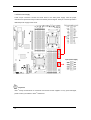
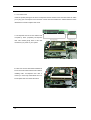
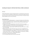
IWILL® H2107™ SERIES 2-Way Server Barebone Hardware Installation Guide Preface Operation is subjected to the following two conditions 1. This device may not cause harmful interference 2. This device must accept any interference received, including interference that may cause undesired operation. IWILL® Corp. makes no warranty of any kind with regard to this material, including, but not limited to, the implied warranties of merchantability and fitness for a particular purpose. IWILL® Corp. shall not be liable for errors contained herein or for incidental or consequential damages in connection with the furnishing, performance, or use of this material. ® IWILL Corp. assumes no responsibility for the use or reliability of its software on equipment that is not ® furnished by IWILL Corp. This document contains proprietary information that is protected by copyright. All rights are reserved. No part of this publication may be reproduced, transcribed, stored in a retrieval system, translated into any language or computer language, or transmitted in any form whatsoever without the prior written consent of IWILL® Corp. © ® Copyright 2005 by IWILL Corp. All rights reserved. Other products and companies referred to herein the trademarks or registered trademarks of their respective companies or mark holders. The information in this document is subject to change without notice. 2 FCC Compliance Statement This equipment has been tested and found to comply with limits for a Class B digital device, pursuant to Part 15 of the FCC rules. These limits are designed to provide reasonable protection against harmful interference in residential installations. This equipment generates, uses, and can radiate radio frequency energy, and if not installed and used in accordance with the instructions, may cause harmful interference to radio communications. However, there is no guarantee that interference will not occur in a particular installation. If this equipment does cause interference to radio or television equipment reception, which can be determined by turning the equipment off and on, the user is encouraged to try to correct the interference by one or more of the following measures: 1. Reorient or relocate the receiving antenna 2. Move the equipment away from the receiver 3. Plug the equipment into an outlet on a circuit different from that to which the receiver is connected 4. Consult the dealer or an experienced radio/television technician for additional suggestions You are cautioned that any change or modifications to the equipment not expressly approve by the party responsible for compliance could void your authority to operate such equipment. This device complies with Part 15 of the FCC Rules. CE Compliance Statement Notice for Europe (CE Mark) This product is in conformity with the Council Directive 89/336/EEC, 92/31/EEC (EMC). 3 Table of Content CHAPTER 1 GETTING STARTED ....................................................................................................6 1-1 PACKING LIST ..................................................................................................................................7 1-2 PRODUCT SKUS................................................................................................................................8 1-3 OPERATING ENVIRONMENTAL REQUIREMENTS ...............................................................................8 1-4 BEFORE POWERING ON THE SYSTEM FOR THE FIRST TIME ................................................................9 1-5 ACTIVATING THE SYSTEM .............................................................................................................10 1-6 ON LAST CHECK .............................................................................................................................10 CHAPTER 2 SYSTEM OVERVIEW.................................................................................................11 2-1 H2107 SERIES SERVER BAREBONE PLACEMENT ...........................................................................12 2-2 H2107 SERIES FEATURES HIGHLIGHT ...........................................................................................13 System: ............................................................................................................................................13 System parts: ...................................................................................................................................13 2-3 H2107 SERIES MAIN BOARD LAYOUT ...........................................................................................16 2-4 CABLE INSTALLATION ...................................................................................................................17 2-4.1 Rear Panel IO ........................................................................................................................17 2-4.2 Front Panel IO .......................................................................................................................19 CHAPTER 3 SYSTEM INSTALLATION.........................................................................................20 3-1 INTRODUCTION OF THE NECESSARY PARTS ...................................................................................21 3-2 INSTALLATION PROCEDURES .........................................................................................................22 CHAPTER 4 HARDWARE INSTALLATION .................................................................................24 4-1 HARDWARE INSTALLATION PROCEDURES .....................................................................................24 4-2 JUMPER SETTING AND INTERNAL CONNECTORS FOR MAINBOARD ................................................25 4-2.1 PCI-X Switch Jumper.............................................................................................................26 4-2.2 VGA Disable ..........................................................................................................................27 4-2.3 Clear CMOS Header..............................................................................................................28 4-2.4 Front Panel Switch Header....................................................................................................29 4-2.5 LAN LED Header...................................................................................................................30 4-2.6 Serial ATA Connector ............................................................................................................31 4-2.7 BMC Connector .....................................................................................................................32 4-3 HEATSINK AND CPU INSTALLATION .............................................................................................33 4-3.1 CPU Installation ....................................................................................................................33 4-3.2 Heatsink Installation ..............................................................................................................36 4 4-4 INSTALL MEMORY .........................................................................................................................37 4-5 MEMORY INSTALLATION PROCEDURES .........................................................................................38 4-6 EPS POWER SUPPLY ......................................................................................................................40 4-7 INSTALL EXPANSION CARDS .........................................................................................................41 4-7.1 Expansion Card Installation Procedure ................................................................................41 4-7.2 Assigning IRQs for PCI Expansion Cards .............................................................................41 4-7.3 PCI-Express Riser Card.........................................................................................................42 CHAPTER 5 BIOS SETUP .................................................................................................................43 5-1 STARTING BIOS SETUP .................................................................................................................44 5-2 UPDATING BIOS SETUP.................................................................................................................45 5-3 USING SETUP .................................................................................................................................47 5-4 MAIN MENU ..................................................................................................................................49 5-5 ADVANCED MENU .........................................................................................................................49 5-5.1 CPU Configuration Submenu ................................................................................................50 5-5.2 IDE Configuration Submenu..................................................................................................50 5-5.3 Floppy Configuration Submenu .............................................................................................51 5-5.4 Super I/O Configuration Submenu.........................................................................................52 5-5.5 Hardware Health Configuration Submenu ............................................................................52 5-5.6 Hyper Transport Configuration Submenu..............................................................................53 5-5.7 MPS Configuration Submenu.................................................................................................53 5-5.8 PCI Express Configuration Submenu ....................................................................................54 5-5.9 Remote Access Configuration Submenu.................................................................................54 5-5.10 USB Configuration Submenu ...............................................................................................55 5-5.11 The Advanced setting description ........................................................................................56 5-6 PCI PNP MENU ..............................................................................................................................57 5-7 BOOT MENU ..................................................................................................................................59 5-7.1 Boot Settings Configuration Submenu ...................................................................................61 5-8 SECURITY MENU ...........................................................................................................................62 5-9 NORTHBRIDGE CHIPSET CONFIGURATION MENU ..........................................................................65 5-9.1 Memory Configuration Submenu ...........................................................................................66 5-9.2 ECC Configuration Submenu.................................................................................................68 5-9.3 IOMMU Mode Submenu ........................................................................................................69 5-10 POWER MENU ..............................................................................................................................70 5-11 EXIT MENU..................................................................................................................................71 CHAPTER 6 TECHNOLOGY SUPPORT ........................................................................................73 5 Chapter 1 Getting Started Congratulations on your purchase of the H2107 Series Server Barebone. Inside 1U rackmount chassis, there is an extremely huge computing power from two AMD Opteron™ processors. The main board of H2107 is based on AMD platform. It is a dual AMD® Opteron micro-Socket 940 motherboard (M/B) based on the NVIDIA® nFORCE™ Professional 2200 MCP chipset. H2107 provides a PCI-Express x8 slot that the transfer speed can reach maximum 4.5GB/Sec. The H2107 Series Server Barebone supports up to sixteen memory DIMMs (eight for each processor installed) accommodating up to 32 GB of memory using registered PC3200/2700/2100 ECC DDR memory modules. slot enables to enter in one add-on card. Additional features such as onboard dual Broadcom® PCI-express Gigabit Ethernet controller and ATi Rage XL video controller providing the highest system capabilities that meet a wide range of demanding workstation and server applications. IWILL H2107 provides two 3.5 drive bays and one slim-type CD-ROM bay. It could support two SATA or SCSI interface hard drive disks with RAID 0, 1 function. 6 Getting Started Flexibility and expandability are provided by one PCI-Express riser card. This PCI 1-1 Packing list Remove all items from the box and make sure you have these following items: 1. H2107 Series Server Barebone 2. IWILL® H2107 Series Server barebone hardware installation guide (This Document) 3. One power cord 4. One PCI-Express Riser Card 5. One PCI-X Riser Card 6. Power Installation CD Kit (including drivers and software) 7. One set of CPU heatsink 8. One set of chassis sliding rail. One set includes two rails. 9. Intelligent Platform Management Interface user’s guide and installation CD (Optional) Please check the quantity of cables and module boards that come assembled inside the H2107 Series system. Cable Board 1 x USB cable 1 x DK88 Board 1 x Power Light cable 1 x BMC card (Optional) 1 x IDE cable for the CD-ROM device 2 x SATA cables (H2107 and H2107-B) 1 x SCSI cable (H2107-A and H2107-C) Important If there are any missing parts, please contact your retailer immediately. 7 1-2 Product Skus Model Name Storage Type Power Supply H2107 SATA 520W power supply H2107-A SCSI 520W power supply H2107-B SATA 400W power supply H2107-C SCSI 400W power supply 1-3 Operating Environmental Requirements To ensure the reliability and performance of H2107 Series Server Barebone, please maintain the operating environment described below: 1. The ambient operating temperature is 0°C to 40°C 2. The relative humidity of operation is 10% to 85% non-condensing. Be aware of the airflow for H2107 Series Server Barebone! The H2107 Series Server Barebone uses forced direct-airflow to cool the system. The above operating conditions should be maintained for reliable operation. In order to avoid conditions which may lead to overheating, please do not let heated exhausted air from other equipment enter: 1. The front of the rack or the cabinet 2. The access panels of the server. Leave your system in the shipping crate at its final destination for 24 hours in the environment where you will set it up. This is to prevent thermal shock and condensation. To minimize the chance of system failure, use the server within the optimal temperature and humidity ranges as follow: 8 1. The optimize ambient temperature of operating is required as 21°C to 23°C 2. The optimize relative humidity of operating is 45% to 50% non-condensing. 1-4 Before powering on the system for the first time H2107 Series is provided with a powerful power supply unit. Locate and connect the AC power cords to the system and an AC power source. There is one power unit in the right of H2107 Series system. Please see the below illustrations to install your power system. Note As the figure 1, you must install the power cord into the power module before you powering on the system. Figure 2 is showing how to connect the power cable to the receptacle. Figure 1 Figure 2 9 1-5 Activating the System After connecting the power cord to the system and AC source, the system can be powered on by pushing the power on button show below. Turn On/Off Reset 1-6 On last check Before powering on the system for the first time it is helpful to avoid any problem by performing one last check. Make sure all AC power is installed and that no parts have dropped down into the system. 10 Chapter 2 System Overview This chapter covers the installation of the system, cabling and system layout. The system specification section will cover the most detail features for the CPU board, IO board, and chassis. This chapter also contains the specifications for the supported processors and memory required for this system. The cabling section will cover the connection and installation for the related devices such as the serial connector, D-sub 15-pin VGA connector, USB connectors, Ethernet Gigabit connectors, and PS/2 connectors at the back System Overview and front panels. 11 2-1 H2107 Series Server Barebone Placement C A B D D B G F E E A 1 x PCI-X or PCI-Express Expansion slot from a 1U riser card B 2 x AMD 940 Pin Opteron™ processors with IWILL Heatsink C EPS 12V 520W Power ( 400W for H2107-B and H2107-C version) D Support 16 x ECC Registered DDR Memory up to 32GB E Support 2 x hot-swap HDD space bays F Support 1 x slim-type CD-ROM space bay G 40*40*28mm 13000RPM fans (Double layer for H2107 and H2107-A) (Single layer for H2107-B and H2107-C) 12 2-2 H2107 Series Features Highlight System: Chassis Type z 1U Server Chassis CPU Type z Dual AMD Opteron Memory Type z 16 DIMMs Registered memory modules up to 32 GB Drive Bays z Support 2 X 3.5” hot-swap HDD spaces TM Processor 200 series z Support 1 x Slim-type CD-ROM space Power Supply z 520W EPS 12V power (H2107 and H2107A) z 400W EPS 12V power (H2107-B and H2107-C) External IO z USB x 3 (2 ports at the rear panel, and 1 port at the front panel) z LAN x 2 z PS/2 connectors x 2 z COM port x 1 z VGA port x 1 System parts: Chassis: Chassis Type z 1U Server Chassis Chassis Dimension z W: 19” x H: 1.75” x D: 27” Chassis Material z SPCC System FAN (H2107-B z 5 x Middle 40*40*28mm 13000RPM fans System FAN (H2107 and H2107-A) z 4 x Middle 40*40*28mm (double layer) 13000RPM fans z 1 x Middle 40*40*28mm (single layer) 13000RPM fans HDD Placement z Support 2 X 3.5” hot-swap HDD spaces z Support 1 x Slim-Type CD-ROM and H2107-C) Mainboard: Processor z Two PGA 940 pin sockets z Support up to two AMD OpteronTM processors 13 System Memory z Support ECC Registered DDR SDRAM memory module z Support up to 32GB memory capacity z 128MB/256MB/512MB/1GB/2GB per DIMM z Support DDR400/333/266 z Total Sixteen 184pin 2.5V DIMM slots z NVIDIA nForce™ Professional 2200 z AMD 8132 PCI-X 2.0Tunnel chip z Winbond W83627THF Super I/O chip z Analog Device ADM 1026 hardware monitor Graphics z Integrated ATI Rage XL w/ 8MB RAM Video Controller LAN z Dual Broadcom PCI-E 5721 Gigabit Ethernet Controllers z Dual RJ-45 ports at the rear panel z One floppy connector z One 9 pin serial port connector z Three internal USB 2.0 headers z Power, HDD and LAN LED pin headers z One BMC connector z Two PS/2 connectors for mouse & keyboard z Two USB 2.0 connectors z One 9 pin serial port connector z One 15 pin VGA connector z Two RJ-45 Giga-bit ports z One PCI-Express x8 slot (By 1U riser card) z Or one PCI-X 64/133 slot (By 1U riser card) z AMI BIOS 8.0 on 4Mbit flash ROM z Support APM 1.2 and ACPI 1.0 z R Server Management BMC card Support IWILL○ Chipset On board IO Rear Panel IO Expansion Slots BIOS System Management 14 z Support IPMI 1.5 z Support KCS interface for inband management z Support RMCP protocol for out-of-band management IPMI z BMC Module Other z Support AC power failure z 8 Layer design 15 2-3 H2107 Series Main Board Layout 4 6 8 2 5 7 1 3 9 10 4 7 1 2 1 Dual AMD Opteron Processors 6 BMC Connector 2 Dual Channel DDR Registered Memory 7 PCI Express x16 slot ( x8 bandwidth) 3 AMD® 8132 PCI-X 2.0 Tunnel 8 PCI-X 64bits 64/100 MHz 4 ATi Rage XL video controller 9 PCI Express x8 slot 5 PCI-X 64bits 64/100/133MHz 10 NVIDIA nForce Professional 2200 MCP * H2107 only provides one expansion slot space. You could install either PCI-Express add-on card or PCI-X add-on card only by different 1U riser cards. 16 2-4 Cable Installation 2-4.1 Rear Panel IO This is an illustration of the Mainboard rear I/O port array. PS/2 Mouse Connector (6-pin Female) The system will direct IRQ12 to the PS/2 mouse if one is detected. If no mouse is detected, IRQ12 will be free for expansion cards to use. PS/2 Keyboard Connector (6-pin Female) This connection is for standard keyboards using a PS/2 (mini DIN) plug. This connector will not accept standard AT size (large DIN) keyboard plugs. You may need a DIN to mini DIN adapter for standard AT keyboards. USB Port Function H2107 Series server system provides the two USB 2.0 ports at the rear panel. USB 2.0 supports 480Mb/second bandwidth providing a marked improvement in device transfer speeds between your computer and a wide range of simultaneously accessible external Plug and Play peripherals. You can connect or disconnect USB cables when the system is turned on. 17 Serial Port Function The serial ports are RS-232C asynchronous communication ports with 16C550A-compatible UARTs that can be used with modems, serial printers, remote display terminals, and other serial devices. It can operate at speeds up to 115,200bps. You can configure the port’s speed in the computer’s Operating System. VGA Port Function The VGA port is for the image output. It can be used with the PC monitor devices. LAN Port Function The LAN port uses a CAT 5 LAN cable for connecting the motherboard to a local area network by means of a network hub. The port has 2 indicator LEDs. Speed LED (right) • 10Mbps - will not blink • 100Mbps - LED is green • 1000Mbps - LED is orange Link and Activity LED (left) • LED is yellow when the LAN connection is linked and accessed. 18 2-4.2 Front Panel IO System LED LAN1 LED LAN2 LED Power LED Turn On/Off Reset USB USB Port Function H2107 Series server system provides one USB 2.0 port at the front panel. You can connect or disconnect USB cables when the system is turned on. Front Section diagram C A B B A 1 x CD-ROM Bay B 2 x hot-swap HDD bays C IO Array 19 Chapter 3 System Installation This chapter mainly covers how to install your system, H2107, to your rack housing on the server room. It will describe how to install the slide rail. This section also introduces the necessary parts of rackmount kit for H2107 Series Server Barebone. Refer to the following illustration for the H2107 Series Server Barebone installation. System Installation 20 3-1 Introduction of the Necessary Parts 2 x H2107 Series Server System Mounting Channel 2 x Inner Rails 4 x “L” Shaped Bracket 1 x H2107 Series Server Barebone 21 3-2 Installation Procedures 1. Disassemble the slide rail 2. Assemble the inner rail onto chassis 22 3. Mount L shape and external rail to rack frame. 4. Insert the chassis into cabinet 23 Chapter 4 Hardware Installation This chapter covers processor and memory installation and hardware configuration. 4-1 Hardware Installation Procedures Installation procedures will be broken down into six major parts. Step 1: Set jumpers Step 3: Install AMD OpteronTM Processors Step 4: Attach cables to connectors Step 5: Install expansion cards Step 6: Connect AC power Warning This H2107 Series Server Barebone contains sensitive electronic components that can be easily damaged by static electricity. Follow the instructions carefully to ensure correct Installation and to avoid static damage. 24 Hardware Installation Step 2: Install memory (DDR memory modules) 4-2 Jumper Setting and Internal Connectors for Mainboard This section covers the jumper setting. Refer to the following illustration for the location of the jumpers. 2 1 3 4 5 6 7 8 9 1 PCI-X_2 Switch 6 PWR Button 2 PCI-X_1 Switch 7 Reset Button 3 VGA Disable 8 Front Panel Switch Header 9 LAN LED Header 4 Clear CMOS Jumper 5 Chassis Intrusion 25 4-2.1 PCI-X Switch Jumper H2107 Series provides two PCI-X slots. By the jumper setting, the slots can be up to 133 MHz or down to 66MHz. Please follow the below instruction. PCI-X 1 Slot ` PCI-X 1 Switch 133MHz 100MHz 66MHz 1 off on off 2 off off on PCI-X 2 Slot PCI-X 2 Switch 1 Off; 2 Off – 133MHz 1 On; 2 Off – 100MHz 1 Off; 2 On – 66MHz 26 4-2.2 VGA Disable This header lets you set your VGA function. When you short this jumper, the onboard ATi video controller would stop work. Then, you have to enter in an additional graphic card. Short Normal Disable Enable (Default) 27 4-2.3 Clear CMOS Header The onboard button cell battery powers the CMOS RAM. It contains all the BIOS setup information. Normally, it is necessary to keep the jumper connected to pin1 and pin2 (Default) to retain the RTC data as shown below. 1 3 1-2 Normal (Default) 2-3 Clear CMOS Follow these instructions to clear the CMOS RTC data: 1. AC off. 2. Short pin2 and pin3 with a jumper for a few seconds. 3. Replace the jumper on pin1 and pin2. 4. Turn on your computer by pressing the power-on button. 5. Hold down <Delete> during boot and select either the <Load Optimal Defaults> or <Load Failsafe Defaults> option in the selection "Exit". Then re-enter BIOS setup to re-enter user preferences. Refer to Chapter 5 BIOS SETUP for more information. 28 4-2.4 Front Panel Switch Header PWR LED This connector connects to the system’s Power LED. When the system’s power is on, this LED will light. HDD Activity LED (2-pin HDD_LED) This connector supplies power to the chassis's HDD/IDE activity LED. Read and Write activity by devices connected to the Primary or Secondary IDE connectors will cause the front panel LED to light up. PWR Switch This switch connects to the system’s Power button allowing you to power on and off the system. You can configure the system to use the keyboard or mouse to power-on the system. You can also configure the system to respond to power restoration after a power outage occurs. These functions can be configured by making appropriate settings in the Integrated Peripherals submenu (“Super IO Device” field) of the BIOS. Reset Switch (2-pin RST) This 2-pin connector connects to the chassis-mounted reset switch for rebooting your computer without turning your power switch off and on. This is a preferred method of rebooting your system to prolong the life of your system’s power supply. 29 4-2.5 LAN LED Header This header is used to connect the RJ-45 LAN ports for the front panel. It can show the LAN speed status to the users in different light colors. Pin 1 LAN1_Active LED Pin 2 LAN1_Link LED Pin 3 LAN1_Link 100 Pin 4 LAN1_Link 1000 Pin 3 LAN2_Active LED Pin 5 LAN2_Link LED Pin 6 LAN2_Link 100 Pin 7 LAN2_Link 1000 Pin 8 Power Pin 9 Power LAN LED Header 30 4-2.6 Serial ATA Connector H2107 supports up to 4 SATA devices each with data transfer rates of 300MB/s. Four Serial ATA ports are supported by nForce™ Professional 2200 MCP. This Main board features four Serial ATA ports for four Serial ATA devices. It uses point to point technology, and supports hot swap. This chipset also supports RAID 0, 1, and 10, which are defined as follows: 4x SATA ports RAID Type Description RAID 0 Striping: high performance, designed to connect multiple drives to act as one Mirroring: writes data to two drives at once in case one drive fails, the other one will be a RAID 1 complete replica and can continue on. Full fail-over Combination of RAID 0 and 1: over 4 drives, The drives are split in half and striped together, RAID 10 and the 2 new striped drives are then mirrored. 7 1 SATA Pin assignments Pin Description 1 GND 2 RXP 3 RXN 4 GND 5 TXN 6 TXP 7 GND Important H2107 supports special NVRAID utility. About NVRAID detail information and user’s manual, please visit IWILL® website: www.iwill.net, or NVIDIA® website: www.nvidia.com 31 4-2.7 BMC Connector H2107 supports Intelligent Platform Management Interface. The IPMI specification defines an internal management bus for extending platform management within a chassis. IPMI functions include remote management access over Serial/Modem and LAN connections, and the capabilities for automatic alerting and recovery. Installation Procedures 1. Before you enter in your BMC card on the DNS-SATA board, please match each pin’s position. Rear of BMC card On board Connector 2. Be gently entering BMC card. 32 4-3 Heatsink and CPU Installation 4-3.1 CPU Installation System mainboard accommodates AMD OpteronTM micro-PGA Socket 940 processors at 2000 MT (Mega Transfer per second). You must insert a CPU into CPU socket 0 (CPU0) first before installing one in CPU socket 1 (CPU1). CPU1 CPU0 Note As with all computer equipment, the processor and motherboard components may be damaged by electrostatic discharge (ESD). Please take proper ESD precautions when handling any board. Warning Do not apply voltage until the heatsink is fully installed. If voltage is applied before the heatsink is fully installed, the processor will overheat and failure will result. Read through the entire installation instructions completely to make sure you understand them before you begin. 33 Follow these instructions to install the CPU. 1. The socket locking lever must be raised (Pull out slightly, and then lift up). 2. Locate the pin 1 of the CPU socket and pin 1 of the CPU. (marked by a triangular hole in the Pin 1 corner) 34 3. Lower the locking lever and latching it into the fully locked position. 35 4-3.2 Heatsink Installation 1. Apply thermal grease to the top of the CPU. Please spread the grease evenly in order to quickly conduct the heat away the processors. 2. Mount the CPU heatsink to the top of the CPU and socket as shown in the following illustration. Secure one side to the motherboard 1 Secure the opposite side 2 3 3. 4 Please follow the number sequence to drive in four screws in order to fix the heatsink well. However, please DO NOT tightly drive in them before you finish all the procedures. 4. After you gently drive in all of screws, please keep the heatsink balance. Then, you can tightly drive in them. 5. If you feel the system is overheating, please shut down the system. Make sure the heatsinks are mounted securely. Tip Make sure that you use the heat-spreading paste between the heatsink and the integrated heat spreader of the processors. Warning Keep the force balanced on both sides of the heatsink when you install the heatsink for CPU or the heat pipe will be bent! 36 4-4 Install Memory The system mainboard uses Dual Inline Memory Modules (DIMM). Two pair’s banks are available; each bank supports one CPU with Hyper Transport Technology. The memory DIMMs accommodates PC2100/2700/3200 (DDR266/DDR333/DDR400) and Double Data Rate Memory (DDR) memory modules in 128MB, 256MB, 512MB, 1GB, and 2GB combinations. Total memory size for one mainboard is between 128MB and 32GB. Important The system mainboard has strict memory type and timing requirements. Before you purchase DDR (Double Data Rate) memory for using in the system mainboard, you should contact your local reseller for a recommend list of system memory that has been validated on this system. Important To take advantage of the 128-bit interface, you must install DIMMs in pairs of two (2). DIMM0 and DIMM1 are paired, and DIMM2 and DIMM3 are paired; DIMM4 and 5 are paired, and DIMM6 and 7 are paired. If you only install two DIMMS into a Memory bank, it is recommended that you install them in slots DIMM0 and DIMM1 to get the full bandwidth. It’s not necessary to install full memory onto both CPU0 and CPU1 memory banks. You could choose to install onto either CPU0 memory bank or CPU1 memory bank when there are two processors on board. Two DDR Modules HO DIMM0, HO DIMM1 Four DDR Modules HO DIMM0, Six DDR Modules HO DIMM0, 1; HO DIMM2, 3; Eight DDR Modules HO DIMM0, 1; HO DIMM2, 3; HO DIMM1, HO DIMM2, HO DIMM3 HO DIMM4, 5 HO DIMM4, 5; HO DIMM6, 7 37 4-5 Memory Installation Procedures 1. Locate the DIMM modules 2. Make sure the DIMM’s pins are facing down, and check that the pin arrangement on the memory module resembles the one pictured below. Important Always populate H0 DIMM socket before installing memory modules in the H1 DIMM sockets. 38 3. Insert the module into the DIMM socket and press down evenly on both ends firmly until the DIMM module is securely in place. (The tabs of the DIMM socket will close-up to hold the DIMM in place when the DIMM is properly installed into the socket.) 39 4-6 EPS Power Supply These 24-pin connectors connect the server board to the EPS power supply. Find the proper orientation and push down firmly to make sure that the pins are aligned. The 8-pin connector provides a dedicated power supply for the CPUs. Important ® IWILL always recommends our customers use EPS12V Power supplies. For any power damaged, please contact your retailer or IWILL® technicians. 40 4-7 Install Expansion Cards Warning Please power off your power supply completely when adding removing any expansion card or other system components. Failure to do so may cause severe damage to both your motherboard and expansion card. 4-7.1 Expansion Card Installation Procedure 1. Read plate on the slot you intend to use. Keep the bracket for possible future use. 2. Carefully align the card's connectors and press with the riser card firmly. 3. Secure the card on the slot with the screw you removed above. 4-7.2 Assigning IRQs for PCI Expansion Cards An IRQ number is automatically assigned to PCI expansion cards. In the PCI bus design, the BIOS automatically assigns an IRQ to a PCI slot that contains a card requiring an IRQ. To install a PCI card, you need to set the INT (interrupt) assignment. Since all the PCI slots on this motherboard use an INTA #, set the jumpers on your PCI cards to INTA. 41 4-7.3 1U Riser Card Inside the system package, there are a PCI-Express and PCI-X Riser Card. This Riser Card can make you to plug your PCI-Express or PCI-X add-on card in the horizontal direction. Please follow the below illustrations to install or replace riser cards. A. PCI-Express and PCI-X slots will be both occupied by IWILL proprietary PCI-Express riser card. Please gently enter in this riser card before you power on your system. B. IWILL PCI-X riser card will be installed into PCI-X 64/133 slot that would be also used for installing IWILL PCI-Express riser card. It means you could only install either PCI-X or PCI-Express riser card at the same time. 42 Chapter 5 BIOS Setup This chapter discusses the AMI BIOS Setup program built into the ROM BIOS. The Setup program allows users modifying the basic system configurations according to their requirements. This special information is then stored in battery-backed RAM so that it retains the Setup information when the power is turned off. The AMI BIOS installed in your computer system's ROM (Read Only Memory) is a custom version of an industry standard BIOS. The BIOS provides critical low-level support for standard devices such as disk drives and serial ports. The AMI BIOS has been customized by adding important, but non-standard, features such as password protection as well as special support for detailed fine-tuning of the chipset controlling the entire system. your system using Setup. BIOS Setup The rest of this chapter is intended to guide you through the process of configuring 43 5-1 Starting BIOS Setup The AMI BIOS is immediately activated when you power on the computer every time. The BIOS reads the system information contained in the CMOS and begins the process of checking out the system and configuring it. After finishing configuring the whole system, then BIOS will continue to seek an operating system on one of the disks, launch then turn control over to the operating system. While the AMI BIOS is in control, the Setup program can be activated in the way: By pressing the <DEL> key when the following message appears briefly at the bottom of the screen during the POST (Power On Self-Test). 44 5-2 Updating BIOS Setup z Creating a bootable floppy disk A、 DOS environment Insert a 1.44 MB floppy disk into the drive. At the DOS prompt, type: format A:/S then press <Enter>. B、 Microsoft® Windows® environment Insert a 1.44 MB floppy disk into the floppy disk drive. From your Windows desktop, click on Start, then select My Computer. Select the 3 1/2 Floppy Drive icon. Click File from the menu, and then select Format. A Format 3 1/2 Floppy Disk window appears. If you are using Windows™, select “Create an MS-DOS startup disk” from the format options field, then click Start. z Move the latest BIOS file to the bootable floppy disk. z Using “AMIFLASH.EXE” to update the BIOS Update the BIOS using the AMIFLASH.EXE utility in DOS environment. 1. Visit the IWILL website ( http://www.iwill.net ) to download the latest BIOS file for your motherboard. Save the BIOS file to a bootable floppy disk. 2. At the DOS prompt, type the command line: AMIFLASH / <filename> where “filename” means the latest (or original) BIOS file that you copied to the bootable floppy disk. The screen displays the status of the update process. Note IWILL H2107 server does not provide a space for an internal floppy device, so, we suggest that you could install a USB-interface floppy outside of the chassis. 45 Important The BIOS information on the screen is for reference only. What you see on your screen may not be exactly the same as shown. Warning DO NOT shutdown or reset the system while updating the BIOS! Doing so may cause system boot failure! Make sure to set protection BIT disable before flash BIOS. 3. When the BIOS update process is complete, the utility returns to the DOS prompt. The AMI BIOS is immediately activated when you power on the computer every time. The BIOS reads the system information contained in the CMOS and begins the process of checking out the system and configuring it. After finishing configuring the whole system, then BIOS will continue to seek an operating system on one of the disks, launch then turn control over to the operating system. While the AMI BIOS is in control, the Setup program can be activated in the way: By pressing the <DEL> key when the following message appears briefly at the bottom of the screen during the POST (Power On Self-Test). z 46 Press <DEL> to enter SETUP 5-3 Using Setup In general, you use the arrow keys to highlight items, press <Enter> to select, press <Esc> to quit. The following table provides more details about how to navigate in the Setup program using the keyboard. Key Function Up Arrow(Ç) Key Move to the previous item Down Arrow(È) Key Move to the next item Left Arrow(Å) Move to the previous item Key Right Arrow(Æ) Key Move to the next item Esc key In the Submenu: Exit the submenu. In the BIOS main category: Quit Without saving changes. Enter Key Select the item. A pop-up selection will display on the screen to set the item value. PgUp Key Previous page on Scrollable menus or jump to the first interactive item listed PgDn Key Next page on Scrollable menus or jump to the last interactive item listed F1 Key General Help on Setup navigation keys. Press <F1> key to pop up a small help window that describes the appropriate keys to use and the possible selections for the highlighted item. To exit the Help Window, press <ESC> key or <F1> key again. F2/F3 Key Change colors F7 Key Discard changes F8 Key Load failsafe defaults F9 Key Load optimal defaults F10 Key Save and Exit Home Go to top of screen End Go to bottom of screen Esc Exit 47 IMPORTANT The BIOS does NOT automatically save values that you have modified. If you do not save your values before you exit the BIOS Setup Utility, all your changes will be lost. If after making and saving system changes with the BIOS Setup Utility, you discover that your computer is no longer able to boot, the AMI BIOS supports an override, which will reset your system to the Failsafe defaults. If that fails, it is possible to manually clear the present CMOS information through the "Clear CMOS Header" on the motherboard (Refer to Jumper Settings for more information). The best advice is to ONLY alter settings which you thoroughly understand. The default settings have been carefully chosen by AMIBIOS to provide the maximum system performance and reliability. Even a slight change to the chipset setup may cause potential and unpredictable failure to the system. 48 5-4 Main Menu This is the first screen that is displayed when you enter the BIOS Setup Utility. Each tab lined on the top of the screen represents each different menu. The following picture shows the main menu. Main menu shows the information of BIOS version, date and ID; processor type, speed and count; system size. In addition, system time and date is adjustable using + / - key or number keys. 5-5 Advanced Menu You can make these modifications on the advanced menu. 49 5-5.1 CPU Configuration Submenu In CPU configuration, you can set up CPU frequency and enable/disable the Error Reporting. GART error reporting should remain disabled for the normal operation. 5-5.2 IDE Configuration Submenu You can make the selections on IDE Configuration menu. 50 Feature Options Description OnBoard PCI IDE Controller Disable Disable: disable controller Primary Secondary Both the integrated IDE Primary: enable only the Primary IDE controller Secondary: enable only the Secondary IDE controller Both: enable both IDE controllers Hard Disk Write Protect Disable Enable Disable/Enable the hard disk write protection. This will be effective only device is accessed through BIOS IDE Detect Time out (sec) 0, 5, 10, 15, 20, 25, 30, 35 Select the time out value for detecting ATA/ATAPI device ATA (PI) 80Pin Cable Detection Host & Device Host Select the mechanism for detecting 80 pin cable Device SATA0 Interface IDE SATA1 Interface IDE Disable Disable/Enable the SATA0 IDE Interface Enable First Boot Device from Disable Disable/Enable the SATA1 IDE Interface Enable P-ATA S-ATA Choice the first boot device when you turn on the system 5-5.3 Floppy Configuration Submenu Important H2107 server does not provide any floppy bay, and it does not recommend using floppy devices. 51 5-5.4 Super I/O Configuration Submenu 5-5.5 Hardware Health Configuration Submenu On this menu, you can monitor the system status. It would show the CPU and system temperature. 52 5-5.6 Hyper Transport Configuration Submenu To set up the hyper transport speed and bandwidth, you can adjust over this menu. The incorrect manipulation will impede the system running. 5-5.7 MPS Configuration Submenu 53 5-5.8 PCI Express Configuration Submenu Enable/Disable PCI Express L0 and L1 link power states. 5-5.9 Remote Access Configuration Submenu 54 5-5.10 USB Configuration Submenu Adjust the USB speed on this submenu. There are two speeds, HiSpeed and FullSpeed, for your configuration. 55 5-5.11 The Advanced setting description Feature Options Description Floppy Configuration Disabled Select Floppy A or Floppy B and then selects floppy-diskette type installed in your system. Hardware Health Configuration Disable/Enable 5 1/2” 360 KB 5 1/2” 1.2 MB 3 1/2” 720 KB 3 1/2” 1.44 MB 3 1/2” 2.88 MB hardware health function and hardware thermal throttling Enable/Disable health function hardware Thermal throttling allows the user to reduce CPU duty cycle to a user defined percentage when the temperature reaches a user defined value H/W health event ACPI Configuration ACPI Aware O/S Enable: O/S supports ACPI Yes/No Disable: O/S doesn’t support ACPI Hyper Transport Configuration CPU0 : CPU1 HT Link Speed/Width Hyper Transport speed/width is adjustable Remote Access Configuration Disable Selects Remote Access type USB Configuration Legacy USB Support Disabled/Enabled/Aut o Serial USB Mass Storage Device Configuration 56 link Enable support for legacy USB Auto option disables legacy support it no USB device connected Configure the USB storage class devices mass 5-6 PCI PnP Menu PCI PnP Menu 1 PCI PnP Menu 2 57 Feature Clear NVRAM Options Description Yes Clear NVRAM during System Boot No Plug & Play O/S Yes No PCI Timer Latency Allocate IRQ to PCI VGA Yes: lets the O/S configure PnP devices not required for boot if your system has a Plug and Play O/S 32, 64, 96, 128, 160, 192, 224, 248 Value in units of PCI clocks for PCI device latency timer register Yes Yes: Assign IRQ to PCI VGA card if card requests IRQ No No: Doesn’t assign IRQ To PCI VGA cars even if card requests IRQ Palette Snooping Enabled Disabled PCI BusMaster IDE Offboard PCI/ISA IDE card Enabled Disabled Auto PCI Slot1 Enabled: informs the PCI devices that an ISA graphics device is installed in the system so the card will function correctly Enabled: BIOS uses PCI busmastering for reading/writing to IDE drives Some PCI IDE cards may require this to be set to the PCI slot number that is holding the card PCI Slot2 PCI Slot3 PCI Slot4 PCI Slot5 PCI Slot6 IRQ3~IRQ15 Available Reserved Available: specified IRQ is available to be used by PCI/PnP devices Reserve: specified IRQ is reserved for use by legacy ISA devices DMA Channel 0, 1, 3, 5, 6, 7 Available Reserved Available: specified DMA is available to be used by PCI/PnP devices Reserve: specified DMA is reserved for use by legacy ISA devices Reserved Memory Size Disabled 16K 32K 64K 58 Size of memory block to reserve for legacy ISA devices 5-7 Boot Menu Boot Menu 1: Boot Settings Boot Menu 2: Boot Device Priority 59 Boot Menu 3: Hard Disk Drives Boot Menu 4: Removable Drives 60 Feature Description Boot Device Priority Specify the boot device priority sequence Hard Disk Drives Specify the boot device priority sequence from available hard drives Removable Drives Specify the boot device priority sequence from available removable drives 5-7.1 Boot Settings Configuration Submenu Feature Options Description Quick Boot Disabled Allow BIOS to skip tests while booting Enabled Quiet Boot Disabled Disabled: Display normal POST messages Enabled Enabled: Display OEM logo Add-on ROM Display Mode Force BIOS Set display mode for option ROM Bootup Num-Lock Off Keep Current Select power on state for Num-Lock On PS/2 Support Mouse Disabled Select support for PS/2 mouse Enabled Typematic Rate Fast Select the speed rate of typematic Slow Wait for “ F1 “ if error Disabled Hit “ DEL “ Message Display Disabled Interrupt Capture Disabled 19 Enabled Enabled Enabled Wait for F1 key to be pressed if error occurs Display “ Press DEL to run Setup “ in POST Enabled: allows option ROMs to trap interrupt 19 61 5-8 Security Menu Security Menu 1: Change Supervisor Password Security Menu 2: Change User Password 62 Security Menu 3: Clear User Password Security Menu 4: Boot Sector Virus Protection 63 Feature Options Description Change Supervisor Password Install or change the password Change Password Install or change the password User Clear User Password Setup: check password while invoking setup Always: check password while invoking setup as well as on each boot Boot Sector Protection 64 Virus Disabled Enabled Enable/Disable protection boot sector virus 5-9 NorthBridge Chipset Configuration Menu 65 5-9.1 Memory Configuration Submenu Feature Options Description Memclock Mode Auto Limit It can be set by the code using AUTO, or if you use LIMIT, you can set one of the standards. MCT Timing Mode See 4-9.1.1 User Config Mode See 4-9.1.1 Bank Interleaving Auto Disabled 8 Beats Burst Length 4 Beats Interleaving allows memory accesses to be spread out over BANKS on the same node, or across NODES, decreasing access contention Burst length can be set to 8 or 4 beats. 64 bit Dq must use the 4 beats 2 Beats Enable Clock to All DIMMs 66 Disable Enable Enable unused clocks to DIMMs even memory slots are NOT populated 5-9.1.1 MCT Timing Mode Submenu MCT Timing Mode User Config Mode 67 5-9.2 ECC Configuration Submenu Feature Options Description DRAM ECC Enable Disabled DRAM ECC allows hardware to report and correct memory errors automatically maintaining system integrity. Enabled L2 Cache BG Scrub Disable 40ns Allows the L2 date cache ram to be corrected while idle. 80ns 160ns 320ns 640ns 1.28us 2.56us 5.12us 10.2us 20.5us 41.0us 81.9us 163.8us 327.7us 655.4us Date Cache Scrub 68 BG See above Allows the L1 date cache ram to be corrected while idle. 5-9.3 IOMMU Mode Submenu Feature Options IOMMU Mode Disabled Description Best Fit Absolute 69 5-10 Power Menu The Power menu items allow you to change the power management settings. Select an item then press Enter to display the configuration options. 70 5-11 Exit Menu Feature Save Changes and Exit Description Exit system setup after saving the changes F10 key can be used for this operation Discard Changes and Exit Exit system setup without saving the changes Discard Changes Discard changes done so far to any of the setup question ESC key can be used for this operation F7 key can be used for this operation Load Optimal Defaults Load optimal default values for all the setup questions F9 key can be used for this operation Load Failsafe Defaults Load Failsafe default values for all the setup questions F8 key can be used for this operation 71 Important Any wrong values setting may cause system to malfunction. Therefore, IWILL suggests loading optimal defaults while any error happens. 72 Chapter 6 Technology Support If a problem arises with yours system during Installation or OS operating, you should ask your dealer for help first as your system has most likely be configured by them. They always have the best idea and quick response for your symptoms. If your dealer is near to your locations, you should bring your system to them to have it quickly serviced instead of attempting to solve the problem by yourself. 1. Go to IWILL® website at www.iwill.net and navigate to this product page which 2. FAQ sections on IWILL® Website are often helpful since other user's questions are often your own. 3. Technology Support contains links to product updates such as Jumper settings or BIOS updates. Email us at: [email protected] and we will try to answer your questions within 24 hours. Three years Warranty If any problems occur during the product’s warranty period, consult your system vendor or distributor before contacting IWILL®. The warranty covers normal customer use of the product. The warranty does not cover damages sustained during shipping or failure due to alteration, misuse, abuse, or improper maintenance of the unit. IWILL® H2107™ Series Server Hardware Installation Guide 73