1
Installation
Manual
•
•
•
•
Installation
Startup
Maintenance
Parts
n WARNING
This manual must only be used by a qualified heating installer/service technician. Read all instructions
in this manual before installing. Perform steps in the order given. Failure to comply could result in
severe personal injury, death or substantial property damage.
NOTICE
Heat Transfer Products, Inc., reserves the right to make product changes or updates without
notice and will not be held liable for typographical errors in literature.
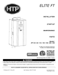
Boiler Manual
GAS-FIRED BOILER
WARNING
If the information in this manual is not followed
exactly, a fire or explosion may result causing
property damage, personal injury or loss of life.
•
•
•
1
Do not store or use gasoline or other flammable
vapors and liquids in the vicinity of this or any
other appliance.
WHAT TO DO IF YOU SMELL GAS
Do not try to light any appliance.
gas supplier's instructions.
Do not touch any electrical switch:
• If you cannot reach your gas
do not use any phone in your
supplier, call the fire department.
building.
Installation and service must be
performed by a qualified installer,
Immediately call your gas supplier
service agency or the gas supplier.
from a neighbor's phone. Follow the
GAS-FIRED BOILER
Boiler Manual
CONTENTS
Part 1 – Product and Safety Information. . . . . . . . . . . . . . . . . . . . . . . . . . . . . . . . . . . . . . 4-6
Part 2 – Before You Start . . . . . . . . . . . . . . . . . . . . . . . . . . . . . . . . . . . . . . . . . . . . . . . . . . . 6-7
A. What’s In The Box
B. How The Boiler Operates
C. Optional Equipment
Part 3 – Prepare Boiler Location . . . . . . . . . . . . . . . . . . . . . . . . . . . . . . . . . . . . . . . . . . . . 7-12
A.
B.
C.
D.
E.
F.
G.
H.
Boiler Location Should Be Level
Installations Must Comply With:
Before Locating Boiler
Clearances for Service Access
Residential Garage Installation
Exhaust Vent and Intake Air Vent
Prevent Combustion Air Contamination
When Removing a Boiler from an Existing Common Vent System
Part 4 – Prepare Boiler . . . . . . . . . . . . . . . . . . . . . . . . . . . . . . . . . . . . . . . . . . . . . . . . . . . 12-13
Part 5 – Boiler Piping . . . . . . . . . . . . . . . . . . . . . . . . . . . . . . . . . . . . . . . . . . . . . . . . . . . . 13-23
A.
B.
C.
D.
E.
F.
G.
H.
I.
J
K.
L.
Relief Valve
General Piping Information
Backflow Preventer
System Water Piping Methods
Circulators
Hydronic Piping with Circulators, Zone Valves and Multiple Boilers
Boiler Piping Details
Circulator Sizing
Fill and Purge Heating System
Zoning with Zone Valves
Zoning with Circulators
Multiple Boilers
Part 6 – Venting, Combustion Air & Condensate Removal . . . . . . . . . . . . . . . . . . . . . 24-34
A.
B.
C.
D.
E.
F.
G.
H.
I.
J.
Installing Exhaust Vent and Intake Air Vent
General
Approved Materials for Exhaust Vent and Intake Air Vent
Exhaust Vent and Intake Air Vent Pipe Location
Exhaust Vent and Intake Air Vent Sizing
Longer Vent Runs
Exhaust Vent and Intake Air Pipe Installation
Heater Removal from a Common Vent System
Diagrams for Sidewall Venting
Diagram for Vertical Venting
Part 7 – Gas Piping. . . . . . . . . . . . . . . . . . . . . . . . . . . . . . . . . . . . . . . . . . . . . . . . . . . . . . 35-39
A.
B.
C.
D.
E.
Gas Connection
Gas Piping
Gas Table
Check Inlet Gas Pressure
Dungs Gas Valve
2
GAS-FIRED BOILER
Boiler Manual
CONTENTS (CONT’D)
Part 8 – Field Wiring. . . . . . . . . . . . . . . . . . . . . . . . . . . . . . . . . . . . . . . . . . . . . . . . . . . . . 40-48
A.
B.
C.
D.
E.
F.
G.
H.
I.
J.
K.
L.
M.
Installation Must Comply With
Field Wiring
Line Voltage Wiring for Standard Boiler
Alarm Connections
Low Voltage Connections for Standard Boiler
Thermostat
Outdoor Sensor
Indirect Sensor
Optional 0-10 Volt Building Control Signal
Optional High Gas Pressure Switch
Optional Low Gas Pressure Switch
Optional UL353 Low Water Cutoff Switch
Wiring of Cascade System Communication Bus
Part 9 – Start Up Preparation . . . . . . . . . . . . . . . . . . . . . . . . . . . . . . . . . . . . . . . . . . . . . 49-52
A.
B.
C.
D.
E.
F.
G.
H.
I.
Check/Control Water Chemistry
Freeze Protection (when used)
Fill and Test Water System
Purge Air from Water System
Check for Gas Leaks
Check Thermostat Circuit(s)
Condensate Removal
Final Checks Before Starting Boiler
Cascade System
Part 10 – Start-Up Procedure . . . . . . . . . . . . . . . . . . . . . . . . . . . . . . . . . . . . . . . . . . . . . 52-54
A.
B.
C.
D.
Operating Instructions
Adjusting the Set Point
Status Menu
Test Mode
Part 11 – Start-Up Procedures for the Installer. . . . . . . . . . . . . . . . . . . . . . . . . . . . . . . 55-57
A. Programming for the Installer
B. Program Access
C. Program Navigation
Part 12 – Troubleshooting. . . . . . . . . . . . . . . . . . . . . . . . . . . . . . . . . . . . . . . . . . . . . . . . 58-61
A. Mod Con Error Code
B. Boiler Error
C. Boiler Fault
Part 13 – Maintenance. . . . . . . . . . . . . . . . . . . . . . . . . . . . . . . . . . . . . . . . . . . . . . . . . . . 61-71
A. Maintenance Procedures
B. Combustion Chamber Coil Cleaning Instructions for Mod Con 300/500 Only
Inspection and Maintenance Start-Up Charts
3
Boiler Manual
GAS-FIRED BOILER
PART 1: PRODUCT AND SAFETY INFORMATION
SPECIAL ATTENTION BOXES
The following defined terms are used throughout this manual to bring attention to the presence of
hazards of various risk levels or to important information concerning the product.
DEFINITIONS
n DANGER
n CAUTION
DANGER indicates an imminently hazardous
situation which, if not avoided, will result in
death or serious injury.
CAUTION Indicates a potentially hazardous
situation which, if not avoided, may result in
minor or moderate injury.
n WARNING
CAUTION
WARNING indicates a potentially hazardous
situation which, if not avoided, could result in
death or serious injury.
CAUTION used without the safety alert symbol
indicates a potentially hazardous situation which,
if not avoided, may result in property damage.
This appliance must be installed by qualified and licensed personnel in accordance with
local codes, or in the absence of local codes, by the national fuel gas code, ANSI Z223.12002. This appliance is for indoor installations only. Clearance to combusitble materials: 0”
top, bottom, sides and back. Front must have room for service, 24” recommended. (A
combustible door or removable panel is acceptable front clearance.) This appliance has
been approved for closet installation. Do not install this appliance directly on carpeting. For
installation on combustible flooring directly. Category IV vent systems only.
4
Boiler Manual
GAS-FIRED BOILER
PART 1: PRODUCT AND SAFETY INFORMATION (CONT’D)
n WARNING
CAUTION
Due to the low water content of the boiler, missizing of the boiler with regard to the heating
system load will result in excessive boiler
cycling and accelerated component failure. Heat
Transfer Products DOES NOT warrant failures
caused by mis-sized boiler applications. DO
NOT oversize the boiler to the system. Modular
boiler installations greatly reduce the likelihood
of boiler oversizing.
Installer — Read all instructions in this manual,
and Mod Con Venting section, before installing.
Perform steps in the order given.
User — This manual is for use only by a
qualified heating installer/service technician.
Refer to User’s Information Manual for your
reference.
User — Have this boiler serviced/inspected by
a qualified service technician annually.
BEFORE INSTALLING
Failure to comply with the above could result in
severe personal injury, death or substantial
property damage.
n WARNING
Failure to adhere to the guidelines on this page
can result in severe personal injury, death or
substantial property damage.
WHEN SERVICING BOILER
•
To avoid electric shock, disconnect electrical
supply before performing maintenance.
•
To avoid severe burns, allow boiler to cool
before performing maintenance.
BOILER OPERATION
n WARNING
•
Do not block flow of combustion or
ventilation air to boiler.
WHAT TO DO IF YOU SMELL GAS
• Do not try to light any appliance.
• Do not touch any electric switch; do not use
any phone in your building.
• Immediately call your gas supplier from a
neighbor's phone. Follow the gas suppliers'
instructions.
• If you cannot reach your gas supplier, call the
fire department.
•
Should overheating occur or gas supply fail to
shut off, do not turn off or disconnect electrical
supply to circulator. Instead, shut off the gas
supply at a location external to the appliance.
•
Do not use this boiler if any part has been
under water. Immediately call a qualified
service technician to inspect the boiler and to
replace any part of the control system and
any gas control that has been under water.
BOILER WATER
5
•
If you have an old system with cast iron
radiators, thoroughly flush the system (without
boiler connected) to remove sediment. The
high-efficiency heat exchanger can be damaged
by build-up or corrosion due to sediment. HTP
recommends a suction strainer in this type of
system.
•
Do not use petroleum-based cleaning or sealing
compounds in boiler system. Gaskets and seals
in the system may be damaged. This can result
in substantial property damage.
•
Do not use “homemade cures” or “boiler patent
medicines.” Substantial property damage,
damage to boiler, and/or serious personal injury
Boiler Manual
GAS-FIRED BOILER
PART 1: PRODUCT AND SAFETY INFORMATION (CONT’D)
may result.
•
Continual fresh make-up water will reduce boiler
life. Mineral buildup in the heat exchanger
reduces heat transfer, overheats the stainless
steel heat exchanger, and causes failure.
Addition of oxygen carried in by make-up water
can cause internal corrosion in system
components. Leaks in boiler or piping must be
repaired at once to prevent make-up water.
FREEZE PROTECTION FLUIDS
n CAUTION
NEVER use automotive or standard glycol
antifreeze, ethylene glycol made for hydronic
systems. Use only inhibited propylene glycol
solutions, which are specifically formulated for
hydronic systems. Ethylene glycol is toxic and
can attack gaskets and seals used in hydronic
systems.
CAUTION
Consider piping and installation when
determining boiler location.
PART 2: BEFORE YOU START
A. WHAT’S IN THE BOX
Also included with the Mod Con are:
•
•
•
•
•
•
Pressure and Temperature Gauge
Outdoor Sensor
Installation Manual
Warranty
CSD-1 Form
H-3 Data Sheet
B. HOW BOILER OPERATES
Mod/Con Condensing Technology is an intelligent system that delivers highly efficient
hydronic heating, while maximizing efficiency
by measuring the data parameters of your heating system. Outlined below are the features of
the system and how they operate:
1. Stainless Steel Heat Exchanger – The highly
efficient Mod/Con Stainless Steel Heat
exchanger is designed to use the cold return
water from the system and extract the last bit
of heat before it is exhausted.
2. Modulating Combustion System – The
combustion system will modulate the output
of the burner during operation to match the
system demand and achieve the control set
point while in operation. The set point can
change by internal or external signals which
enhance the overall performance of the
system.
3. Control – The integrated control system
monitors the system and regulates the fan
speed to control the boilers output. This
allows the boiler to only deliver the amount
of heated energy required and nothing more.
This control can be set up to monitor outdoor
temperature through an outdoor sensor to
regulate the set point of the boiler. The
system can be further enhanced by
connecting up to an indirect water heater to
provide domestic hot water.
The control can regulate the output of
multiple boilers through its cascade system
function. The cascade system is capable of
connecting up to eight boilers together in
such a way that they function as one boiler
system. This allows for greater turn down
ratios and provides systematic control of the
multiple boilers in an installation to minimize
downtime and maximize efficiency.
The cascade system works by establishing
one boiler as the master and the other
connected boilers as followers. The master
boiler will have a cascade system sensor and
a cascade pump connected to it in addition to
its own boiler pump. The follower boilers will
6
GAS-FIRED BOILER
Boiler Manual
PART 2: BEFORE YOU START (CONT’D)
have their own individual pump connected to
each follower boiler.
4. System Display and Operation Led light
Indicators – The display allows the user to
change the system parameters and monitor
the system outputs. Led light indicators
monitor operation through illumination of
Indirect Pump – Boiler Pump – System Pump
– Flame On – System Fault.
5. Gas Valve – The gas valve senses suction
from the blower allowing gas to flow only if
the gas valve is powered and combustion air
is flowing.
6. Swirl Plate or Integrated Venturi – Controls
the air and gas flow into the burner.
7. Burner – Constructed of high grade stainless
steel, the burner uses premixed air gas and
provides a wide range of firing rates.
8. Spark Ignition – The burner is ignited by
applying a high voltage through the system
spark electrode. This causes the spark from
the electrode to ignite the mixed gas off of
the burner.
9. Supply Water Temperature Sensor – This
sensor monitors the boiler outlet water
temperature (System Supply). The control
adjusts the boiler firing rate so the supply
temperature will match the boiler set point.
10. Return Water Temperature Sensor – This
sensor monitors the boiler return water
temperature (System Return). The control
adjusts the boiler firing depending on how
close the return water temperature is to the
supply water temperature.
11. Temperature and Pressure Gauge – Allows
the user to monitor the system temperature
and pressure.
12. Electrical field connections with terminal
strips – The electrical cover allows easy
access to the line voltage and low voltage
terminals strips which are clearly marked to
facilitate wiring of the boiler.
13. Condensation Collection System – This boiler
is a high efficiency appliance, therefore the
boiler will produce condensate. The collection
system has a float switch to monitor the
condensation level to prevent condensation
from backing up into the combustion system.
Inside the collection system there is a built in
trap to seal the combustion system to the
connected drain. This condensate should be
neutralized to avoid damage to the drainage
system or piping.
14. Outdoor Sensor – The outdoor sensor will
monitor the outdoor temperature and adjust
the unit’s set point to provide greater
efficiency.
C. OPTIONAL EQUIPMENT
Below is the list of optional equipment available
for Mod Con Boiler.
• System Sensor (Part # 7250P-324)
• Indirect Sensor (Part # 7250P-325)
• 4” Stainless Steel Outside Termination Vent
Kit (V3000)
• 6” Stainless Steel Outside Termination Vent
Kit (V4000)
• High and Low Gas Pressure Switch Kit with
Manual Reset (Part # 7350P-600)
• U.L. 353 Compliant Low Water Cut-Off
Interface Kit with Manual Reset (Part # 7350P601)
• Alarm System (Part # 7350P-602) (to monitor
any failure)
• Stacking Kit (Part # 7350P-603)
• PC Connection Kit (Part # 7350P-320)
• Boiler Caster Kit (Part # 7350P-404)
• Mod Con Condensate Neutralizer (Part #
7350P-611)
These additional options may be purchased
through your HTP Distributor.
PART 3: PREPARE BOILER LOCATION
A. BOILER LOCATION SHOULD BE LEVEL
Before considering the Boiler location, there are
7
many factors that have to be addressed that are
covered in detail in this installation manual.
Please read the entire manual as it could save
Boiler Manual
GAS-FIRED BOILER
PART 3: PREPARE BOILER LOCATION (CONT’D)
time and money. Piping, Venting, Condensation
Removal are just a few issues that need to be
addressed prior to the installation of the boiler.
n CAUTION
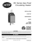
When preparing the boiler location, make sure the area where you are placing the boiler is level. In order
for the condensate properly to flow out of the collection system, the boiler must be level to assure proper
flow direction. The Mod Con Boiler comes equipped with leveling feet. Should you find the floor beneath
the boiler is uneven, with a wrench, adjust the leveling feet.
INCORRECT
CORRECT
INCORRECT
CORRECT
8
Boiler Manual
GAS-FIRED BOILER
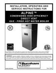
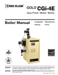
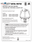
DIMENSIONS
/()76,'(
02'&21
)5217
$//02'(/6
32:(56:,7&+
',63/$<3$1(/
+27:$7(5
287/(7
$&&(663$1(/
5,*+76,'(
02'&21
(/(&75,&$/%2;
&2/':$7(5
,1/(7
+
.
$
/
)
%
&
*
*$6/,1(
-
/(*6$'-867
'
(
&21'(16$7(
',6&+$5*(
5,*+76,'(
02'&21
/()76,'(
02'&21
5($5
$//02'(/6
(;+$867
$&&(663$1(/
(/(&75,&$/%2;
0
$,5,17$.(
02'(/
$
%
&
'
(
)
*
+
-
.
/
0
02'&21
02'&21
02'&21
3/($6(127($//',0(16,216$5($3352;,0$7($1'+(,*+76'2127,1&/8'($'-867$%/(/(*6
02'(/
%78+5
,1387
/2:),5(
%78+5
,1387
+,*+),5(
'2(
+($7,1*
&$3$&,7<
02'&21
)$163(('6
+,*+
/2:
,*1,7,21
02'&21
02'&21
Figure 2-1
9
6833/<5(7851
*$6
9(17
&211(&7,21 &211(&7,21 ',$0(7(5
LP-205-C Rev. 5/6/08
Boiler Manual
GAS-FIRED BOILER
PART 3: PREPARE BOILER LOCATION (CONTINUED)
B. INSTALLATIONS MUST COMPLY WITH:
•
Local, state, provincial, and national codes,
laws, regulations and ordinances.
•
National Fuel Gas Code, ANSI Z223.1 – latest
edition.
•
Standard for Controls and Safety Devices for
Automatically Fired Boilers, ANSI/ASME
CSD-1, when required.
•
National Electrical Code.
•
For Canada only: B149.1 or B149.2
Installation Code, CSA C22.1 Canadian
Electrical Code Part 1 and any local codes.
•
•
•
•
Incorrectly-sized expansion tank.
Lack of freeze protection in boiler water
causing system and boiler to freeze and leak.
Excessive glycol which will affect the
boiler system operation.
Clean and flush system when re-installing
a boiler.
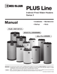
D. CLEARANCES FOR SERVICE ACCESS
1. See Figure 3-1 for recommended service
clearances. If you do not provide minimum
clearances shown, it might not be possible to
service the boiler without removing it from
the space.
NOTICE
SERVICE CLEARANCES
The Mod Con Boiler gas manifold and controls
met safe lighting and other performance criteria
when the boiler underwent tests specified in
ANSI Z21.13 — latest edition.
C. BEFORE LOCATING THE BOILER
1. Check for nearby connections to:
• System water piping
• Venting connections
• Gas supply piping
• Electrical power
• Condensate drain
2. Check area around boiler. Remove any
combustible materials, gasoline and other
flammable liquids.
RQO\
Figure 3-1
LP-205-M Rev. 5/27/08
n WARNING
n WARNING
Failure to keep boiler area clear and free of
combustible materials, gasoline and other
flammable liquids and vapors can result in
severe personal injury, death or substantial
property damage.
The space must be provided with combustion/ventilation air openings correctly sized for
all other appliances located in the same space as
the Mod Con Boiler. The boiler cover must be securely fastened to the boiler to prevent the boiler from drawing air from inside the boiler room.
This is particularly important if the boiler is located in the same room as other appliances.
Failure to comply with the above warnings could
result in severe personal injury, death or substantial property damage.
3. T h e M o d C o n G a s C o n t r o l S y s t e m
components must be protected from dripping
water during operation or service.
4. If the Mod Con Boiler is to replace an existing
boiler, check for and correct any existing
system problems such as:
• System leaks.
10
Boiler Manual
GAS-FIRED BOILER
PART 3: PREPARE BOILER LOCATION (CONTINUED)
E. RESIDENTIAL GARAGE INSTALLATION
Precautions
Take the following special precautions when
installing the boiler in a residential garage. If the
boiler is located in a residential garage, per ANSI
Z223.1, paragraph 5.1.9:
•
Mount the boiler with a minimum of 18
inches above the floor of the garage to the
bottom of the boiler to ensure the burner and
ignition devices will be no less than 18 inches
above the floor.
•
Locate or protect the boiler so it cannot be
damaged by a moving vehicle.
F. EXHAUST VENT AND INTAKE AIR VENT
n WARNING
Vents must be properly supported. The Mod
Con’s Intake and Exhaust Connections are not
designed to carry heavy weight. Vent support
brackets must be within 1 foot of the boiler and
the balance at 4 foot intervals. The Mod Con
venting must be readily accessible for visual
inspection for the first three feet from the boiler.
The Mod Con Boiler requires a special vent system, designed for pressurized venting. Mod Con
Boilers are rated ANSI Z21.13 Category IV (pressurized vent, likely to form condensate in the
vent).
You must also install air intake piping from outdoors to the boiler flue adaptor. The resultant
installation is categorized as direct vent (sealed
combustion). Note: To prevent combustion
air contamination see Table 3-2 in this
section when considering exhaust vent
and intake air vent termination.
Intake and exhaust must terminate near each
other and may be vented vertically through the
roof or out a side wall. The intake and exhuast
venting methods are detailed in the Venting
Section. Do not attempt to install the Mod Con
Boiler using any other means. Be sure to locate
the boiler such that the air intake and exhaust
vent piping can be routed through the building
and properly terminated. The air intake and
exhaust vent piping lengths, routing and termination method must all comply with the methods
and limits given in the venting section.
11
G. PREVENT COMBUSTION AIR
CONTAMINATION
Install intake air piping for the Mod Con Boiler as
described in the Venting section. Do not terminate exhaust in locations that can allow contamination of intake air.
n WARNING
You must pipe outside air to the boiler air
intake. Ensure that the intake air will not
contain any of the contaminants below.
Contaminated air will damage the boiler,
resulting in possible severe personal injury,
death or substantial property damage. For
example, do not pipe intake air vent near a
swimming pool. Also avoid areas subject to
exhaust fumes from laundry facilities. These
areas will always contain contaminants.
Table 3-2: Corrosive contaminants and sources
Products to avoid
Spray cans containing fluorocarbons
Permanent wave solutions
Chlorinated waxes/cleaners
Chlorine-based swimming pool chemicals
Calcium chloride used for thawing
Sodium chloride used for water softening
Refrigerant leaks
Paint or varnish removers
Hydrochloric acid/muriatic acid
Cements and glues
Antistatic fabric softeners used in clothes dryers
Chlorine-type bleaches, detergents, and cleaning
solvents found in household laundry rooms
Adhesives used to fasten building products and
other similar products
Areas likely to have contaminants
Dry cleaning/laundry areas and establishments
Swimming pools
Metal fabrication plants
Beauty shops
Refrigeration repair shops
Photo processing plants
Auto body shops
Plastic manufacturing plants
Furniture refinishing areas and establishments
New building construction
Remodeling areas
Garages and workshops
Boiler Manual
GAS-FIRED BOILER
PART 3: PREPARE BOILER LOCATION (CONTINUED)
connected to the common venting system
are located and other spaces of the building.
Turn on clothes dryers and any appliance not
connected to the common venting system.
Turn on any exhaust fans, such as range
hoods and bathroom exhausts, so they will
operate at maximum speed. Do not operate
a summer exhaust fan. Close fireplace
dampers.
H. WHEN REMOVING A BOILER FROM AN
EXISTING COMMON VENT SYSTEM
n DANGER
Do not install the Mod Con Boiler into a common
vent with any other appliance. This will cause
flue gas spillage or appliance malfunction,
resulting in possible severe personal injury,
death or substantial property damage.
n WARNING
Failure to follow all instructions can result in flue
gas spillage and carbon monoxide emissions,
causing severe personal injury or death.
At the time of removal of an existing boiler, the
following steps shall be followed with each
appliance remaining connected to the common
venting system placed in operation, while the
other appliances remaining connected to the
common venting system are not in operation.
a. Seal any unused openings in the common
venting system.
b. Visually inspect the venting system for
proper size and horizontal pitch and
determine that there is no blockage or
restriction, leakage, corrosion or other
deficiencies which could cause an unsafe
condition.
c. Insofar as is practical, close all building doors
and windows and all doors between the
space in which the appliances remaining
d. Place in operation the appliance being
inspected. Follow the lighting instructions.
Adjust thermostat so appliance will operate
continuously.
e. Test for spillage at draft hood opening after 5
minutes of main burner operation. Use the
flame of a match or candle, or smoke from a
cigarette, cigar, or pipe.
f.
After it has been determined that each
appliance remaining connected to the
common venting system properly vents
when tested as outlined herein, return doors,
windows, exhaust fans, fireplace dampers
and any other gas-burning appliance to their
previous conditions of use.
g. Any improper operation of common venting
system should be corrected so the
installation conforms with the National Fuel
Gas Code, ANSI Z223.1 — latest edition.
Correct by resizing to approach the minimum
size as determined using the appropriate
tables in Table 13 of NFPA54 ANSI Z223.1
2006 of that code. Canadian installations
must comply with B149.1 or B149.2
Installation Code.
PART 4: PREPARE BOILER
n WARNING
CAUTION
Uncrating Boiler – Any Claims for damage or
shortage in shipment must be filed immediately
against the transportation company by the
consignee.
Cold weather handling — If boiler has been
stored in a very cold location (below 0°F) before
installation, handle with care until the plastic
components come to room temperature.
Remove all sides of the Mod Con shipping crate
in order to allow the boiler to be lifted into its
installation location. You must pick the boiler up
by the lift rings to avoid damage to the boiler
12
Boiler Manual
GAS-FIRED BOILER
PART 4: PREPARE BOILER (CONTINUED)
enclosure. You can use either a solid
¾” in diameter black iron pipe or lifting straps to lift the boiler off of its
shipping crate. You must have at least
two individuals to handle the boiler
properly to avoid damage as care
should be taken as the Mod Con is
very heavy. The Mod Con is also
equipped with leveling feet that can
be used to level the boiler properly if
the surface location is not level. If surface flooring is rough, care should be
taken when sliding boiler into position, you could catch the leveling feet
and damage the boiler if it is slid to its
location.
,16(57%/$&.,5213,3(:,7+7((6
25/,)7,1*675$36
,172/,)7,1*5,1*63529,'('
$/:$<6/,)7:,7+$7/($673(23/(
/,)7,1*5,1*6
PART 5: BOILER PIPING
A. RELIEF VALVE
Connect discharge piping to a safe disposal location, follow the guidelines in the WARNING below.
n WARNING
To avoid water damage or scalding due to relief valve operation:
• Discharge line must be connected to relief valve outlet and run to a safe place of disposal. Terminate
the discharge line in a manner that will prevent possibility of severe burns or property damage should
the valve discharge.
• Discharge line must be as short as possible and be the same size as the valve discharge connection
throughout its entire length.
• Discharge line must pitch downward from the valve and terminate at least 6” above the floor drain
where any discharge will be clearly visible.
• The discharge line shall terminate plain, not threaded, with a material serviceable for temperatures of
375 °F or greater.
• Do not pipe the discharge to any place where freezing could occur.
• No shutoff valve shall be installed between the relief valve and boiler, or in the discharge line. Do not
plug or place any obstruction in the discharge line.
• Test the operation of the valve after filling and pressurizing system by lifting the lever. Make sure the
valve discharges freely. If the valve fails to operate correctly, replace it with a new relief valve.
• Failure to comply with the above guidelines could result in failure of the relief valve to operate,
resulting in possibility of severe personal injury, death or substantial property damage.
13
Boiler Manual
GAS-FIRED BOILER
PART 5: BOILER PIPING (CONTINUED)
B. GENERAL PIPING INFORMATION
NOTICE
The Mod Con Boiler control module uses
temperature sensors to provide both high limit
protection and modulating temperature control.
The control module also provides low water
protection by sensing the water level in the heat
exchanger. Some codes/jurisdictions may
require additional external controls.
recognized design methods. See tank
manufacturer’s instructions for details.
3. Connect the expansion tank to the air
separator only if the separator is on the
suction side of the circulator. Always install
the system fill connection at the same point
as the expansion tank connection to the
system.
4. Most chilled water systems are piped using a
closed type expansion tank.
Diaphragm (or bladder) expansion tank
C. BACKFLOW PREVENTER
Use a backflow preventer specifically designed
for hydronic boiler installations. This valve
should be installed on the cold water fill supply
line per local codes. (See Boiler Piping Details)
CAUTION
All piping methods shown in this manual use
primary/secondary connection to the boiler loop.
This is to avoid the possibility of inadequate flow
through the boiler. For other piping methods,
consult your local Heat Transfer Products
representative or refer to separate Mod Con
Boiler piping details in this manual (Part 5).
D. SYSTEM WATER PIPING METHODS
Expansion tank and make-up water
1. Ensure that the expansion tank size will
handle boiler and system water volume and
temperature. Allow for boiler and its piping:
Mod Con 300
2.9 Gallons
Mod Con 500
4.2 Gallons
Mod Con 850
5.8 Gallons
CAUTION
Undersized expansion tanks cause system
water to be lost from relief valve and makeup
water to be added through a fill valve. Eventual
boiler failure can result due to excessive makeup water addition. This type of failure is NOT
covered by warranty.
2. The expansion tank must be located as
shown in Boiler Piping Part 5 or following
1. Always install an automatic air vent on top of
the air separator to remove residual air from
the system.
E. CIRCULATORS
n CAUTION
DO NOT install automatic air vents on closedtype expansion tank systems. Air must remain
in the system and return to the tank to provide
its air cushion. An automatic air vent would
cause air to leave system, resulting in waterlogging the expansion tank.
n CAUTION
DO NOT use the boiler circulator in any location
other than the ones shown in this manual. The
boiler circulator is selected to ensure adequate
flow through the Mod Con Boiler. Failure to
comply could result in unreliable performance
and nuisance shut downs from insufficient flow.
Sizing space heat system piping
1. See Piping Details in this manual Part 5. In all
diagrams, the space heating system is
isolated from the boiler loop by the
primary/secondary connection.
2. Size the piping and components in the space
heating system using recognized design
methods.
F. HYDRONIC PIPING WITH CIRCULATORS,
ZONE VALVES AND MULTIPLE BOILERS
The Mod Con Boiler is designed to function in a
closed loop Hydronic System. We have also included a Temperature and Pressure gauge that al14
GAS-FIRED BOILER
Boiler Manual
PART 5: BOILER PIPING (CONTINUED)
lows the user to monitor the system pressure and
outlet temperature from the Mod Con Boiler. It is
important to note that the Mod Con Boiler has a
minimal amount of pressure drop and must be calculated when sizing the circulators. Each Mod Con
Boiler installation must have an Air Elimination device that will remove air from the system. Install the
Mod Con Boiler so the gas ignition system components are protected from water (dripping, spraying, etc.) allowing clearance for basic service of
boiler circulator, valves and other components.
Observe minimum 1” clearance around all un-insulated hot water pipes when openings around
pipes are not protected by non-combustible materials. On a Mod Con Boiler installed above radiation level, some states and local codes require a
low water cut off device which is standard on the
Mod Con boiler. Check with local codes for additional requirements. If the Mod Con Boiler supplies
15
hot water to heating coils in air handler units, flow
control valves or other devices must be installed to
prevent gravity circulation of boiler water in the
coils during the cooling cycle. Chilled Water
Medium must be piped in parallel with the boiler.
Freeze Protection for new or existing systems must
use glycol that is specifically formulated for this
purpose. It will include inhibitors that will prevent
the glycol from attacking the metallic system components. Make certain that the system fluid is
checked for the correct glycol concentration and inhibitor level. The system should be tested at least
once a year and as recommend by the producer of
the glycol solution. Allowance should be made for
the expansion of the glycol solution in the system
piping. Example 50% by volume gycol solution expands 4.8% in volume for the temperature increase
from 32 F to 180 F, while water expands 3% with
the same temperature rise.
Boiler Manual
GAS-FIRED BOILER
PART 5: BOILER PIPING (CONTINUED)
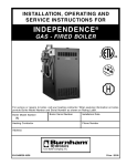
G. BOILER PIPING DETAILS
Single Mod Con Boiler Space Heating with Indirect Priority
%$//9$/9(
7<3,&$/
3,3(',$0(7(5
63$&,1*0$;,080
$,5(/,0,1$725
)520
6<67(0
6833/<6(1625
237,21$/
6<67(0
&,5&8/$725
'5$,1
9$/9(
%2,/(5
&,5&8/$725
7<3,&$/
(;3$16,21
7$1.
726<67(0
'5$,19$/9(
385*(32,17
7(03(5$785(
35(6685(*$8*(
0$.(83
:$7(5
%$&.)/2:
35(9(17(5
35(6685(5('8&,1*
9$/9(
35(6685(*$8*(
02'&21
%2,/(5
$17,6&$/'
0,;,1*9$/9(
+27:$7(5
287/(7
&2/':$7(5
,1/(7
+27:$7(5
&,5&8/$725
6:,1*&+(&.9$/9(
81,21
7<3,&$/
35(6685(
5(/,()
9$/9(
'5$,19$/9(
NOTES:
1. This drawing is meant to show system piping concept only.
2. An Anti-Scald mixing valve is recommended if the DHW temperature is set above the factory setting
of 119°F.
3. Install a minimum of 12 diameters of straight pipe upstream of all circulators.
4. Piping shown is Primary/Secondary
5. System Flow (Secondary Loop) must be greater than the boiler’s primary loop flow.
LP-205-L Rev. 5/14/08
16
Boiler Manual
GAS-FIRED BOILER
PART 5: BOILER PIPING (CONTINUED)
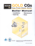
Cascade Multiple Mod Con Boilers with
Indirect Priority on One Boiler
%$//9$/9(
7<3,&$/
3,3(',$0(7(5
63$&,1*0$;,080
$,5(/,0,1$725
)520
6<67(0
6833/<6(1625
6<67(0
&,5&8/$725
'5$,1
9$/9(
(;3$16,21
7$1.
'5$,19$/9(
385*(32,17
72
6<67(0
0$.(83:$7(5
%$&.)/2:35(9(17(5
35(6685(5('8&,1*9$/9(
35(6685(*$8*(
,1',5(&7
+27:$7(5
7$1.
%2,/(5
&,5&8/$725
7<3,&$/
$17,6&$/'
0,;,1*9$/9(
+27:$7(5
287/(7
&2/':$7(5
,1/(7
%2,/(5
0$67(5
'20(67,&
+27:$7(5
&,5&8/$725
81,21
7<3,&$/
6:,1*&+(&.9$/9(
7<3,&$/
'5$,19$/9(
7<3,&$/
7(0335(6685(*$8*(
%2,/(5
)2//2:(5
%2,/(5
)2//2:(5
35(6685(5(/,()9$/9(
NOTES:
1. This drawing is meant to show system piping concept only.
2. An Anti-Scald mixing valve is recommended if the DHW temperature is set above the factory setting
of 119°F.
3. Install a minimum of 12 diameters of straight pipe upstream of all circulators.
4. Piping shown is Primary/Secondary
5. Reference Figure 5-2 to determine manifold pipe sizing.
6. System Flow (Secondary Loop) must be greater than the boiler’s primary loop flow.
LP-205-J Rev. 5/14/08
17
Boiler Manual
GAS-FIRED BOILER
PART 5: BOILER PIPING (CONTINUED)
Single Mod Con Boiler
Space Heating
3,3(',$0(7(5
63$&,1*0$;,080
%$//9$/9(
7<3,&$/
$,5(/,0,1$725
)5206<67(0
6833/<6(1625
237,21$/
6<67(0
&,5&8/$725
'5$,19$/9(
%2,/(5
&,5&8/$725
6:,1*&+(&.
9$/9(7<3,&$/
(;3$16,21
7$1.
726<67(0
'5$,19$/9(
385*(32,17
0$.(83
:$7(5
%$&.)/2:
35(9(17(5
35(6685(
5('8&,1*
9$/9(
35(6685(
*$8*(
81,21
7<3,&$/
'5$,19$/9(
35(6685(5(/,()
9$/9(
NOTES:
1.
2.
3.
6.
This drawing is meant to show system piping concept only.
Install a minimum of 12 diameters of straight pipe upstream of all circulators.
Piping shown is Primary/Secondary
System Flow (Secondary Loop) must be greater than the boiler’s primary loop flow.
LP-205-R Rev. 5/14/08
18
Boiler Manual
GAS-FIRED BOILER
PART 5: BOILER PIPING (CONTINUED)
Cascade Mod Con Boilers
Space Heating Only
%$//9$/9(
7<3,&$/
$,5(/,0,1$725
3,3(',$0(7(5
63$&,1*0$;,080
6833/<6(1625
237,21$/
)5206<67(0
6:,1*&+(&.
9$/9(7<3,&$/
'5$,19$/9(
6<67(0
&,5&8/$725
(;3$16,21
7$1.
'5$,19$/9(
385*(32,17
726<67(0
%2,/(5
&,5&8/$725
7<3,&$/
0$.(83:$7(5
%$&.)/2:35(9(17(5
35(6685(5(&8',1*9$/9(
35(6685(*$8*(
%2,/(5
&,5&8/$725
7<3,&$/
%2,/(5
0$67(5
81,21
7<3,&$/
'5$,19$/9(
7<3,&$/
7(0335(6685(
*$8*(
7<3,&$/
%2,/(5
)2//2:(5
%2,/(5
)2//2:(5
35(6685(5(/,()
9$/9(
NOTES:
1. This drawing is meant to show system piping concept only.
2. An Anti-Scald mixing valve is recommended if the DHW temperature is set above the factory setting
of 119°F.
3. Install a minimum of 12 diameters of straight pipe upstream of all circulators.
6. System Flow (Secondary Loop) must be greater than the boiler’s primary loop flow.
LP-205-Q Rev. 5/14/08
19
GAS-FIRED BOILER
Boiler Manual
PART 5: BOILER PIPING (CONTINUED)
n CAUTION
The Mod Con Boiler should not be operated as
a potable Hot Water Heater. It should not be
used as a direct Hot Water Heating Device.
Basic steps are listed below, with Illustration,
that will guide you through the installation of the
Mod Con.
1. Connect the system return marked “Boiler
Return”.
2. Connect the system supply marked “Boiler
Supply”.
3. Install Purge and Balance Valve or shut off
valve and drain on system return to purge air
out of each zone.
4. Install a Back Flow preventor on the Cold Feed
Make-Up Water line.
5. Install a Pressure Reducing Valve on the Cold
Feed Make-Up Water line, (15 PSI nominal on
the system return). Check Temperature and
Pressure Gauge when operating. It should
read minimum pressure of 12 PSI.
6. Install a circulator as shown in piping details
(this section). Make sure the circulator is
properly sized for the system and friction loss.
7. Install an Expansion Tank on the system
supply. Consult the tank manufacturer’s
instruction for specific information relating to
expansion tank installation. Size the expansion
tank for the required system volume and
capacity.
8. Install an Air Elimination Device on the system
supply.
9. Install a drain valve at the lowest point of the
system. Note: The Mod Con Boiler can not be
drained completely of water without purging
the unit with an air pressure 15 PSI.
10. The relief valve is installed at the factory. A
pipe discharge line should be installed 6”
above the drain in the event of a pressure
relief. The pipe size must be the same size as
the relief valve outlet. NEVER BLOCK THE
OUTLET OF THE SAFETY RELIEF VALVE.
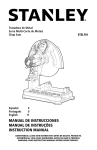
H. CIRCULATOR SIZING
The Mod Con Boiler Heat Exchanger does have
pressure drop which must be considered in
your system design. Refer to the graph in Fig. 51 for pressure drop through the Mod Con Boiler
Heat Exchanger.
20
Boiler Manual
GAS-FIRED BOILER
PART 5: BOILER PIPING (CONTINUED)
FRICTION
IN FEET PRESSURE
OF HEAD DROP
MOD CON HEAT
EXCHANGER
90
80
70
FLOW OF GPM
60
50
40
30
20
10
0
2
4
6
8
10
12
14
16
18
20
22
24
26
28
30
32
34
36
FRICTION IN FEET OF HEAD
MODCON 300
MODCON 500
MODCON 850
Figure 5-1
The chart below represents the various system design temperature rise through the Mod Con along
with their respective flows and friction loss which will aid in circulator selection.
SYSTEM TEMPERATURE RISE CHART
20°Δt
25°Δt
30°Δt
35°Δt
40°Δt
45°Δt
Friction Flow Friction Flow Friction Flow Friction Flow Friction Flow Friction Flow
Feet
GPM
Feet
GPM
Feet
GPM
Feet
GPM
Feet
GPM
Feet
GPM
Mod Con 300
19’
30
12’
24
9’
20
7’
17
6’
15
5’
14
Mod Con 500
19’
50
11’
40
8’
33
6’
28
5’
25
4’
23
Mod Con 850
35’
85
26’
65
18’
54
12’
45
10’
40
8’
36
Model
LP-205-E Rev. 12/5/07
21
Boiler Manual
GAS-FIRED BOILER
PART 5: BOILER PIPING (CONTINUED)
The chart below represents the combined flow
rates and pipe sizes when using multiple boilers
to design the manifold system for the primary
circuit. To size, simply add up the number of
boilers and the required flow rates for the system design temperature.
Example (5) Mod Con 300 Boilers with a design
of 30 degree temperature rise with each boiler
having an individual flow rate of 20 GPM. To correctly size the manifold feeding these (5) Mod
Con 300 Boilers you would need a pipe size of
3”.
Combined
Pipe Sizing
Multiple
BoilerBoiler
Manifold
Piping
7
Pipe Diameter Size (Inches)
6
5
4
3
2
1
0
0
100
200
300
400
500
600
700
800
Combined Boiler Water Flow (GPM)
Figure 5-2
MULTIPLE BOILER MANIFOLD PIPING
Flow rate 30
Pipe Dia.
50
60
85
2” 2½” 2½” 3”
90 100 120 150 170 180 200 210 240 250 255 300 340 350 400 425 510 595 680
3”
3”
4”
4”
4”
4”
I. FILL AND PURGE HEATING SYSTEM
•
•
•
Attach the hose to balance and purge hose
connector or drain valve and run hose to
nearest drain
Close the other side of the balance and purge
valve or the shut off valve after the drain.
Open first zone balance and purge or drain
valve to let water flow out the hose. If zone
valves are used, open the valves one at a
time manually. (Note: You should check valve
manufacturer’s instruction prior to opening
valves manually, so as not to damage the
valve.)
4”
4”
•
•
5”
5”
5”
5”
5”
5”
5”
5”
6”
6”
6”
Manually operate fill valve regulator. When
water runs out of the hose, while it’s
connected to the balance and purge valve or
drain you will see a steady stream of water
(without bubbles). Close balance and purge
valve or drain to stop the water from flowing.
Disconnect the hose and connect it to next
zone to be purged.
Repeat this procedure for additional zones
(one at time).
22
Boiler Manual
GAS-FIRED BOILER
PART 5: BOILER PIPING (CONTINUED)
n CAUTION
n CAUTION
For installation that incorporates standing iron
radiation and systems with manual vents at the
high points. Follow previous section and
starting with the nearest manual air vent, open
vent until water flows out, then close vent.
Repeat procedure, working your way toward
furthest air vent. It may be necessary to install
a basket strainer in an older system where
larger amounts of sediment may be present.
Annual cleaning of the strainer may be
necessary.
It is highly recommended that you carefully
follow the glycol manufacturer’s recommended
concentrations, expansion requirements and
maintenance recommendations (pH additive
breakdown, inhibitor reduction, etc.). You must
carefully figure the additional friction loss in the
system as well as the reduction in heat transfer
co-efficients.
J. ZONING WITH ZONE VALVES
Upon completion, make sure that the fill valve is
in the automatic position and each zone balance
and purge or shut off is in an open position and
zone valves are positioned for automatic operation.
1. Connect the boiler to the system as shown in
Piping Details when zoning with zone valves.
The primary/secondary piping shown
ensures the boiler loop will have sufficient
flow. It also avoids applying the high head of
the boiler circulator to the zone valves.
n WARNING
2. Connect DHW (domestic hot water) piping to
indirect storage water heater as shown.
Use only inhibited propylene glycol solutions
which are specially formulated for hydronic
systems. Ethylene glycol is toxic and can attack
gaskets and seals used in hydronic systems.
Glycol mixtures should not exceed 50%.
1. Glycol in hydronic applications which is
specially formulated for this purpose includes
inhibitors that prevent the glycol from attacking
metallic system components. Make certain that
the system fluid is checked for the correct
glycol concentration and inhibitor level.
2. The glycol solution should be tested at least
once a year and as recommended by the
glycol manufacturer.
3. Anti-freeze solutions expand more than
water. For example a 50% by volume solution
expands 4.8% in volume for a temperature
increase from 32° F to 180° F, while water
expands 3% with the same temperature rise.
Allowances must be made for this expansion
in the system design.
K. ZONING WITH CIRCULATORS
1. Connect the boiler to the system when using
circulator zoning as shown in Piping Details
when zoning with circulators. NOTE: The
boiler circulator cannot be used for a zone. It
must supply only the boiler loop.
2. Install a separate circulator for each zone.
3. Connect DHW (domestic hot water) piping to
indirect storage water heater as shown in
Piping Details.
L. MULTIPLE BOILERS
1. Connect multiple boilers as shown in Piping
Details.
2. All piping shown is reverse return to assure
balanced flow throughout the connected
boilers.
3. Each connected boiler must have its own
circulator pump to assure adequate flow.
4. A 30% mixture of glycol will result in a BTU
output loss of 15% with a 5% increase in
head against the system circulator.
4. Connect DHW (domestic hot water) piping to
indirect storage water heater as shown in
Piping Details.
5. A 50% mixture of glycol will result in a BTU
output loss of 30% with a 50% increase in
head against the system circulator.
5. The system flow (secondary loop) must be
greater than the boiler’s primary loop flow.
23
GAS-FIRED BOILER
Boiler Manual
PART 6: VENTING, COMBUSTION AIR & CONDENSATE REMOVAL
A. INSTALLING EXHAUST VENT AND
INTAKE AIR VENT
n DANGER
n WARNING
Use only the materials listed in table 6-1 for the
venting systems. Failure to do so could result
in severe personal injury, death or substantial
property damage.
The Mod Con Boiler must be vented as detailed
in this section. Ensure the exhaust and intake
piping comply with these instructions regarding
the venting system.
Inspect finished combustion air intake and
exhaust piping thoroughly to ensure all joints
are secure and airtight and comply with all
applicable code requirements, as well as with
the instructions provided in this manual.
Failure to provide a properly installed vent
system will cause severe personal injury or
death.
1. Installations must be made with a vent pipe
system certified to ULC-S636. IPEX is an
approved vent manufacturer in Canada in
Canada supplying vent material listed to
ULC-S636. Additionally you may use AL244C
stainless steel venting to comply with
Canadian requirements.
n WARNING
2. The first three (3) feet of vent pipe from the
appliance flue outlet must be readily
accessible for visual inspection.
This vent system will operate with a positive
pressure in the pipe. Do not connect vent
connectors serving appliances vented by natural
draft into any portion of mechanical draft
systems operating under positive pressure.
Follow these venting instructions carefully.
Failure to do so may result in severe personal
injury, death, or substantial property damage.
REQUIREMENTS FOR INSTALLATION
IN CANADA
3. The components of the certified vent system
must not be interchanged with other vent
systems or unlisted pipe / fittings.
n WARNING
Do not use Cellular Foam Core Pipe in any portion
of the exhaust piping from this boiler. Use of
Foam Core Pipe may result in severe personal
injury, death, or substantial property damage.
B. GENERAL
1. Install the boiler venting system in
accordance with these instructions and with
t h e N a t i o n a l Fu e l G a s C o d e , A N S I
Z223.1/NFPA 54, CAN/CGA B149, and/or
applicable provisions of local building codes.
Cellular foam core piping may be used on air
inlet piping only.
2. This boiler is a direct vent appliance and is
listed as a Category IV appliance with
Underwriters Laboratories, Inc.
C. APPROVED MATERIALS FOR EXHAUST
VENT AND INTAKE AIR VENT
1. Use only Non Foam Core venting material or
AL294C. The following materials are
approved for use as vent pipe for this boiler.
See Table 6-1 for all approved venting.
24
GAS-FIRED BOILER
Boiler Manual
PART 6: VENTING, COMBUSTION AIR & CONDENSATE REMOVAL (CONTINUED)
Table 6-1
APPROVED PLASTIC EXHAUST VENTING MATERIAL
STANDARDS FOR INSTALLATION IN:
UNITED STATES
CANADA
PVC SCHEDULE 40
ANSI /ASTM D1785
ULC S636**
ANSI /ASTM D2665
ULC-S636**
PVC -DWV
CPVC SCHEDULE 40
ANSI /ASTM F441
ULC- S636**
**Note: IPEX is an approved
*Note: Cellular Foam Core Pipe must only
Manufacturer in Canada
be used on INTAKE piping.
supplying vent material listed to
ULC-S636
MATERIAL
Table 6-2
APPROVED PLASTIC INTAKE VENTING MATERIAL
STANDARDS FOR INSTALLATION IN:
UNITED STATES
CANADA
PVC SCHEDULE 40
ANSI /ASTM D1785
ULC S636**
CPVC SCHEDULE 40
ANSI /ASTM F441
ULC- S636**
PVC DWV
ANSI /ASTM D2665
N/A
PVC-CELLULAR FOAM CORE*
U.L. LISTED
N/A
**Note: IPEX is an approved
*Note: Cellular Foam Core Pipe must only
Manufacturer in Canada
be used on INTAKE piping.
supplying vent material listed to
ULC-S636
MATERIAL
Table 6-3
APPROVED PLASTIC CONDENSATE PIPING MATERIAL
MATERIAL
STANDARDS FOR INSTALLATION IN:
UNITED STATES
CANADA
PVC SCHEDULE 40
ANSI /ASTM D1785
ULC S636**
**Note: IPEX is an approved
Manufacturer in Canada
supplying vent material listed to
ULC-S636
Table 6-4
APPROVED PIPE CEMENT AND PRIMER FOR PLASTIC PIPE
MATERIAL
STANDARDS FOR INSTALLATION IN:
CEMENT AND PRIMER
UNITED STATES
CANADA
CPVC
ANSI/ASTM F493
IPEX System 636
PVC
ANSI/ASTM D2564
Cements and Primers
Table 6-5
APPROVED METALLIC EXHAUST VENTING MATERIAL
MATERIAL
STANDARDS FOR INSTALLATION IN:
UNITED STATES
CANADA
AL294C
U.L.LISTED
U.L.LISTED
Table 6-6
APPROVED METALLIC INTAKE VENTING MATERIAL
STANDARDS FOR INSTALLATION IN:
UNITED STATES
CANADA
"B" GAS VENT
U.L. LISTED
U.L. LISTED
GALVANIZED
U.L. LISTED
U.L. LISTED
MATERIAL
Table 6-7
APPROVED STAINLESS STEEL VENT ADAPTERS AND TERMINATIONS
Z-FLEX PART NUMBER
Mod Con 300 & 500
HTP PART NUMBER
2SVSMK04
Boiler Adapter 4"
7250P-732
2SVSRTF04
Horizontal Vent Terminal 4"
7350P-607
2SVSRCF04
Rain Cap 4"
7350P-609
Z-FLEX PART NUMBER
Mod Con 850
HTP PART NUMBER
2SVEP06.5
Boiler Adapter 6"
7350P-114
2SVSRTX06
Horizontal Vent Terminal 4"
7350P-608
2SVSRCF06
Rain Cap 6"
7350P-610
25
Boiler Manual
GAS-FIRED BOILER
PART 6: VENTING, COMBUSTION AIR & CONDENSATE REMOVAL (CONTINUED)
n WARNING
You must not use “B” Vent in an exhaust
application. ‘B’ vent is for intake applications
only. Failure to do so will result in serious injury
or death.
removal may be necessary to maintain
clearance.
•
Provide 4 feet horizontal clearance from
electrical meters, gas meters, gas
regulators, relief equipment, exhaust fans
and inlets. In no case shall the exit
terminal be above or below the
aforementioned equipment unless the 4
foot horizontal distance is maintained.
Both exhaust and intake air vents must exit
from the same side of the building to assure
correct appliance operation.
•
Do not locate the exhaust over public
walkways where condensate could drip
and/or freeze and create a nuisance or
hazard.
D. EXHAUST VENT AND INTAKE AIR VENT
PIPE LOCATION
•
Please refer to chart below for U.L.-approved
stainless steel adapters and terminations.
When adjacent to a public walkway,
locate exit terminal at least 7 feet above
grade.
•
Do not locate the exhaust directly under
roof overhangs to prevent icicles from
forming.
•
Provide 6 feet clearance from the inside
corner of vertical walls, chimneys, etc., as
well as horizontal corners created by roof
overhangs.
n WARNING
1. Determine exhaust vent location:
• Total length of vent may not exceed the
limits specified in the venting Sizing
Section.
•
•
The vent piping for this boiler is approved
for zero clearance to combustible
construction.
See illustration within this section of
clearances for location of exit terminals of
direct-vent venting systems.
• Avoid terminating exhaust vent near
shrubs, air conditioners or other objects
that will obstruct the exhaust stream.
• The flue products coming from the
exhaust vent will creat a large plume wne
the boiler is in operation. Avoid venting in
areas that will affect neighboring
buildings or be considered objectionable.
•
The boiler vent system shall terminate at
least 3 feet (0.9 m) above any forced air
intake located within 10 ft (3 m). Note:
this does not apply to the combustion air
intake of a direct-vent appliance.
•
Provide a minimum of 1 foot distance
from any door, operable window, or
gravity intake into any building.
•
Provide a minimum of 1 foot clearance
from the bottom of the exhaust above the
expected snow accumulation level. Snow
2. Determine air intake vent location.
•
Provide 1 foot clearance from the bottom
of the intake air vent and the level of
maximum snow accumulation. Snow
removal may be necessary to maintain
clearances.
•
Do not locate intake air vent in a parking area
where machinery may damage the pipe.
•
Follow required minimum clearances
located in Fig. 6-3, 6-4, 6-5.
3. Determine location of Condensate Piping
This boiler is a high efficiency appliance,
therefore the boiler produces condensate.
Condensate is a by-product of the boiler
combustion process. A condensate
collection system with an internal float switch
monitors the condensate level to prevent it
from backing up into the combustion system.
There is a ¾” sweat connection provided to
connect the outlet of the collection system to
a drain or condensate pump. (See table 6-1
for approved condensate piping material)
26
GAS-FIRED BOILER
Boiler Manual
PART 6: VENTING, COMBUSTION AIR & CONDENSATE REMOVAL (CONTINUED)
CAUTION
It is very important that the condensate piping
be no smaller than ¾” and you must use a tee
at the condensate connection with the branch
vertically up and open to the atmosphere so it
will not cause a vacuum that could obstruct the
flow of condensate from the boiler. The
condensate piping should also be properly
supported with pipe supports to prevent
sagging and to maintain the pitch of the piping.
4. Condensate Neutralization
The condensate from the boiler is slightly
acidic with a ph of 3.2 - 4.5 Heat Transfer
27
Products recommends neutralizing the
condensate with a Condensate Neutralizer Kit
(p/n 7350P-611) that can be added to your
system to avoid long term damage to the
drainage system and to meet local code
requirements. The neutralizer kit is connected
to the drain system and contains marble
chips that will neutralize the ph level of the
water vapor. The neutralizer should be
checked at least once a year and the marble
chips should be replenished if necessary.
When replacing the marble chips, they
should no smaller than ¾” to avoid blockage
in condensate piping. (Refer to fig 6-1 and 62 for piping of the Condensate neutralizer.)
Boiler Manual
GAS-FIRED BOILER
PART 6: VENTING, COMBUSTION AIR & CONDENSATE REMOVAL (CONTINUED)
&21'(16$7(1(875$/,=(5
:,7+2873803
6:($739&7((
23(172$70263+(5(
3,3(+$1*(5
$66(0%/,(6
)256833257
&21'(16$7(
1(875$/,=(5
39&6:($7
3,3,1*),77,1*6
)/225'5$,1
+25,=217$//,1(6
0867%(,167$//(':,7+
$3,7&+2)3(5)227
&21'(16$7(1(875$/,=(5
:,7+3803
3,3(6833257
&/($12873257
:$51,1*<2808670$.(685(7+$77+,6&$3
,66(&85($)7(56(59,&,1*)$,/85(72'262
&28/'5(68/7,16(5,286,1-85<25'($7+
6:($739&7((
23(172$70263+(5(
6:($739&
3,3,1*),77,1*6
Fig. 6-1
3,3(+$1*(5
$66(0%/,(6)25
6833257
/,77/(*,$173803
&21'(16$7(
1(875$/,=(5
+25,=217$//,1(60867%(,167$//('
:,7+$3,7&+2)3(5)227
3,3(6833257
&/($12873257
:$51,1*<2808670$.(685(7+$77+,6&$3
,66(&85($)7(56(59,&,1*)$,/85(72'262
&28/'5(68/7,16(5,286,1-85<25'($7+
Fig. 6-2
LP-205-W Rev. 5/7/08
CAUTION
NOTICE
The condensate line must remain unobstructed,
allowing free flow of condensate. If condensate
is allowed to freeze in the line or if the line is
obstructed in any other manor, condensate can
exit from the boiler tee, resulting in potential
water damage to property.
When installing a condensate pump, select one
approved for use with condensing boilers and
furnaces. The pump should have an overflow
switch to prevent property damage from
condensate spillage.
Condensate from the Mod Con Boiler will be
slightly acidic (typically with a pH from 3.2 to
4.5). Install a neutralizing filter if required by
local codes.
28
GAS-FIRED BOILER
Boiler Manual
PART 6: VENTING, COMBUSTION AIR & CONDENSATE REMOVAL (CONTINUED)
Location of exit terminals of mechanical draft and direct-vent venting systems.
(Reference: National Fuel Gas Code ANSI Z223.1/NFPA 54 2002).
Fig. 6-3 Multiple Vents
Fig. 6-4 Multiple Vent Spacing*
*Note: Exhaust must extend out 1 foot. There should be no more than 2 vents and 2 intakes then a space of 36” to the
next set of vents.
*Note: There must be a minimum of 36” spacing between every 2 kit grouping.
Multiple “V” Series Vents
Fig. 6-5 Multiple Stainless Steel Horizontal Vent Kit Installation – Front View
29
Boiler Manual
GAS-FIRED BOILER
PART 6: VENTING, COMBUSTION AIR & CONDENSATE REMOVAL (CONTINUED)
E. EXHAUST VENT AND INTAKE AIR VENT
SIZING
1. The exhaust vent and intake air vent pipes
are 4" for the Mod Con 300 and 500, and 6"
for the Mod Con 850.
2. The total combined equivalent length of
exhaust vent and intake air pipe should not
exceed 200 feet.
a. The equivalent length of elbows, tees,
and other fittings are listed in the Friction
Loss Table 6-8.
Table 6-8
Friction Loss Equivalent for
Stainless or Plastic Piping and Fittings
F. LONGER VENT RUNS
1. The maximum combined equivalent length
can be extended by increasing the diameter
of both exhaust vent and intake air vent pipe
equally. However, the transitions should
begin a minimum of 15 equivalent feet from
the boiler on both the intake and exhaust
equally.
a. The maximum equivalent length for the
increased diameter vent pipes is 275 feet,
which includes the combined 30 feet from
the boiler, 15 ft. (inlet) + 15 ft. (exhaust) =
30 ft. combined with transition total of 245
ft. upsize piping for longer vent runs.
Table 6-9
Fitting Description
4"
6"
8"
90° elbow short radius
3'
3'
3'
Size
Reducing Coupling
Final Vent Size
90° elbow long radius
2'
2'
2'
4" venting
6" x 4"
6"
45° elbow
1'
1'
1'
6" venting
8" x 6"
8"
Coupling
0'
0'
0'
Tee (intake only)
0'
0'
0'
V Series Vent Kit
1'
1'
1'
AL29 4C Vent Terminal 1'
1'
1'
Pipe (All materials)
1’
1’
1’
*Friction loss for long radius elbow is 1 foot less.
b. For example: If the exhaust vent has two
short 90° elbows and 10 feet of PVC pipe
we will calculate:
Exhaust Vent Pipe Equivalent Length = (2x3)+10=16 feet
Vent Transition Fitting
b. Transitions must always be made in
vertical sections of pipe to prevent the
condensate from pooling in the vent
pipe.
c. If the transition occurs at a distance
greater than 15 equivalent feet from the
boiler, the maximum equivalent length
will be reduced.
G. EXHAUST VENT AND INTAKE AIR PIPE
INSTALLATION
Further, if the intake air vent pipe has two
90° elbows, one 45° elbow and 10 feet of
PVC pipe, the following calculation
applies:
1. Use only solid PVC, or CPVC schedule 40 or
80 pipe and AL294C Stainless Steel. FOAM
CORE PIPING IS ONLY ALLOWED FOR
INTAKE PIPING.
Intake Air Vent Pipe Equivalent Length = (2x3)+1+10=17 feet
2. Remove all burrs and debris from joints and
fittings.
c. The intake air vent pipe and the exhaust
vent are intended to penetrate the same
wall or roof of the building.
d. Effort should be made to keep a
minimum difference in equivalent length
between the intake air vent pipe and the
exhaust vent.
3. The minimum combined equivalent length is
15 equivalent feet.
3. All joints must be properly cleaned, primed,
and cemented. Use only cement and primer
approved for use with the pipe material.
Refer to the Venting Table 6-4.
n WARNING
All joints of positive pressure vent systems
must be sealed completely to prevent leakage
of flue products into the living space.
30
GAS-FIRED BOILER
Boiler Manual
PART 6: VENTING, COMBUSTION AIR & CONDENSATE REMOVAL (CONTINUED)
4. Horizontal lengths of exhaust vent must slope
back towards the boiler not less than ¼" per
foot to allow condensate to drain from the
vent pipe. If the exhaust pipe must be piped
around an obstacle that results in the creation
of a low point, condensate will collect in this
low point and form a blockage. This
condensate must be drained away using a
field-installed condensate drain assembly. All
vent pipes must be glued, properly
supported and the exhaust must be pitched
a minimum of ¼” per foot back to the boiler
to allow drainage of condensate. The
condensate drain piping should be a
minimum of ¾” PVC Rigid Piping, pitched at
a minimum of ¼” per foot away from the
boiler. (See Fig. 6-1, 6-2)
5. All piping must be fully supported. Use pipe
hangers at a minimum of 4 foot intervals to
prevent sagging of the pipe where
condensate may form. When placing support
brackets on vent piping, the first bracket must
be within 1 foot of the appliance and the
balance at 4 foot intervals on the vent pipe.
The boiler venting must be readily accessible
for visual inspection for the first three feet of
the boiler.
6. Do not use the boiler to support any piping.
7. A screened straight coupling is provided with
the boiler for use as an outside exhaust
termination.
8. A screened inlet air tee is provided with the
boiler to be used as an outside intake
termination.
H. HEATER REMOVAL FROM A COMMON
VENT SYSTEM
At the time of removal of an existing heater, the
following steps shall be followed with each
appliance remaining connected to the common
venting system placed in operation, while the
other appliances remaining connected to common venting system are not operating.
1. Seal any unused openings in the common
venting system.
31
2. Visually inspect the venting system for proper
size and horizontal pitch to determine if there
is blockage, leakage, corrosion or other deficiencies that could cause an unsafe condition.
3. If practical, close all building doors, windows
and all doors between the space in which the
appliance remains connected to the common
venting system located and other spaces in
the building. Turn on clothes dryers and any
appliances not connected to the common
venting system. Turn on any exhaust fans,
such as range hoods and bathroom exhausts,
at maximum speed. Do not operate a summer
exhaust fan. Close all fireplace dampers.
4. Place in operation the appliance being
inspected. Follow the lighting instructions.
Adjust the thermostat so the appliance will
operate continuously.
5. Test for spillage at the draft hood relief
opening after 5 minutes of main burner
operation. Use the flame of a match or candle
or smoke from a cigarette.
6. After it has been determined that each
appliance remaining connected to common
venting system properly vents when tested as
outlined, return doors, windows, exhaust fans,
fireplace dampers and any other gas burning
appliance to their previous condition of use.
7. Any improper operation of the common
venting system should be corrected so the
installation conforms with the National Fuel
Gas Code, ANSI Z223.1. When resizing any
portion of the common venting system, the
common venting system should be resized to
approach the minimum size as determined
using the appropriate tables in Appendix G in
the National Fuel Gas Code, ANSI Z 223.1
Note: For Canadian Installations, it is required
that Non Metallic Vent Installations conform to
ULC S636. Where plastic venting is not allowed,
HTP recommends AL294C Stainless Steel
Venting be used for Exhaust venting installations and “B” vent for intake air.
Please refer to 6-7 below for U.L. Approved
Stainless Steel Vent Adapters.
Boiler Manual
GAS-FIRED BOILER
PART 6: VENTING, COMBUSTION AIR & CONDENSATE REMOVAL (CONTINUED)
I. DIAGRAMS FOR SIDEWALL VENTING
SIDEWALL VENTING W/TEE (INTAKE)
AND COUPLING (EXHAUST)
$,5,17$.(
9(17
SIDEWALL VENTING WITH KIT
7((
0$;
9(17.,7
6((&+$57
675$,*+7
&283/,1*
7239,(:
(;+$867
9(17
6833257%5$&.(76
0867%(86('21
$//+25,=217$/
$1'9(57,&$/3,3,1*
(;+$867
9(17
0,1
25
$%29(0$;
327(17,$/612:/(9(/
0,1
6833257%5$&.(76
0867%(86('21
$//+25,=217$/
$1'9(57,&$/3,3,1*
675$,*+7
&283/,1*
(;+$867
9(17
7((
25
$%29(0$;
327(17,$/612:/(9(/
5,*+76,'(9,(:
,17$.($,5
9(17
5,*+76,'(9,(:
$,5,17$.(
9(17
127(9(170867%($7/($6729(50$;,080612:
/(9(/25:+,&+(9(5,6*5($7(5&+(&.:,7+/2&$/
&2'(5(48,5(0(176
127(9(170867%($7/($6729(50$;,080612:
/(9(/25:+,&+(9(5,6*5($7(5&+(&.:,7+/2&$/
&2'(5(48,5(0(176
Figure 6-9
LP-205-E Rev. 5/15/08
Figure 6-10
LP-205-F Rev. 5/15/08
GENERAL NOTE: All vent pipes must be glued, properly supported and the exhaust must be pitched a
minimum of a ¼" per foot back to the heater (to allow drainage of condensate).
NOTE: When placing support brackets on vent piping, the first bracket must be within 1 foot of the
appliance and the balance at 4 foot invervals on the vent pipe. The boiler venting must be readily
accessible for visual inspection for the first three feet from the boiler.
32
Boiler Manual
GAS-FIRED BOILER
PART 6: VENTING, COMBUSTION AIR & CONDENSATE REMOVAL (CONTINUED)
J. DIAGRAM FOR VERTICAL VENTING
ROOF VENT WITH TEE (INTAKE)
AND COUPLING (EXHAUST)
675$,*+7
&283/,1*
0,1
0,1
7((
29(50$;,080
612:/(9(/25
:+,&+(9(5,6*5($7(5
(;+$867
9(17
5,*+76,'(9,(:
(;7(5,25:$//
,17$.($,5
9(17
Figure 6-11
LP-205-G Rev. 5/6/08
NOTE: When placing support brackets on vent piping, the first bracket must be within 1 foot of the
appliance and the balance at 4 foot invervals on the vent pipe. The boiler venting must be readily
accessible for visual inspection for the first three feet from the boiler.
GENERAL NOTE: All vent pipes must be glued, properly supported and the exhaust must be pitched a
minimum of a ¼" per foot back to the heater (to allow drainage of condensate).
33
Boiler Manual
GAS-FIRED BOILER
PART 6: VENTING, COMBUSTION AIR & CONDENSATE REMOVAL (CONTINUED)
0,1
0,1
522)(;+$867
5$,1&$367$,1/(6667((/
=)/(;6965&)
=)/(;6965&
522)9(17,1*:,7+
67$,1/(6667((/$/&
$,5,17$.(
*$/9$1,=('%9(17
29(50$;,080
612:/(9(/25
:+,&+(9(5,6*5($7(5
6833257
%5$&.(76
6,'(:$//9(17,1*
:,7+67$,1/(6667((/
6,'(:$//(;+$867
7(50,1$7,21
=)/(;69657)
=)/(;69657;
6833257
%5$&.(76
$,5,17$.(
*$/9$1,=('
%9(17
RU
$%29(0$;
327(17,$/
612:/(9(/
127(9(170867%($7/($6729(50$;,080612:
/(9(/25:+,&+(9(5,6*5($7(5&+(&.:,7+/2&$/
&2'(5(48,5(0(176
Figure 6-12
LP-205-Y Rev. 5/28/08
NOTE: When placing support brackets on vent piping, the first bracket must be within 1 foot of the
appliance and the balance at 4 foot invervals on the vent pipe. The boiler venting must be readily
accessible for visual inspection for the first three feet from the boiler.
GENERAL NOTE: All vent pipes must be glued, properly supported and the exhaust must be pitched a
minimum of a ¼" per foot back to the heater (to allow drainage of condensate).
34
Boiler Manual
GAS-FIRED BOILER
PART 7: GAS PIPING
n WARNING
Failure to follow all precautions in this section
could result in fire, explosion or death!
A. GAS CONNECTION
The gas supply shall have a maximum inlet
pressure of less than 14" w.c. (3.5 kPa), and a
minimum of 3.5" w.c. (.87 kPa). The entire piping
system, gas meter and regulator must be sized
properly to prevent pressure drop greater than
0.5" (.12 kPa) as stated in the National Fuel Gas
Code. This information is listed on the rating
label.
SS
M
S
S
(
If the leak test requirement is a higher test pressure than the maximum inlet pressure, you must
isolate the Mod Con from the gas line. In order
to do this, you must shut the gas off using factory and field-installed gas cocks. This will prevent high pressure. Failure to do so may damage the gas valve. In the event the gas valve is
exposed to a pressure greater than ½ PSI, 14"
w.c. (3.5 kPa), the gas valve must be replaced.
Never use an open flame (match, lighter, etc.) to
check gas connections.
B. GAS PIPING
1. Run the gas supply line in accordance with all
applicable codes.
2. Locate and install manual shutoff valves in accordance with state and local requirements.
Y
3. In Canada, the Manual Shutoff must be
identified by the installing contractor.
)
4. It is important to support gas piping as the
unit is not designed to structurally support
large amount of weight.
5. Purge all gas lines thoroughly to avoid start
up issues with air in the lines.
S
n WARNING
It is very important that you are connected to
the type of gas as noted on the rating plate.
“LP” for liquefied petroleum, propane gas or,
“Nat” natural or city gas. You must not do a gas
conversion on this boiler. All gas connections
must be approved by the local gas supplier, or
utility in addition to the governing authority,
prior to turning the gas supply on.
The gas connection on the Mod Con is 1-1/4” for
the Mod Con 300, 1-1/2” for the Mod Con 500
and 2” for the Mod Con 850. It is mandatory that
this fitting is used for connection to a field fabricated drip leg as shown in the illustration above
per the National Fuel Gas Code. You must
ensure that the entire gas line to the connection
at the Mod Con is no smaller than the unit supplied connection. Once all the inspections have
been performed, the piping must be leak tested.
35
6. Sealing compound must be approved for gas
connection. Care must be taken when
applying compound to prevent blockage or
obstruction of gas flow which my effect the
operation of the unit.
n WARNING
Never use an open flame (Match or Lighter) to
check for Gas leaks. Use A soapy solution to
test gas connection for leaks. Failure to use
soapy solution test or check gas connection for
leaks can cause substantial property damage,
severe personal injury or death .
NOTICE
CSA or UL listed Flexible gas connections can
be used when installing The Mod Con Boiler.
Flexible gas connections have different
capacities and must be sized correctly for the
connected boiler firing rates. Consult with the
flex line supplier to assure the line size is
adequately sized for the job. Follow local codes
for proper installation and service requirements.
Boiler Manual
GAS-FIRED BOILER
PART 7: GAS PIPING (CONTINUED)
C. GAS TABLE
Maximum Capacity of Pipe in Cubic Feet of Gas
per Hour for Gas Pressures of 0.5 w.c. or Less and
a Pressure Drop of 0.3 Inch w.c.
Refer to Table 7-1 to size the supply piping to
minimize pressure drop between meter or
regulator and unit.
Table 7-1
NATURAL GAS SUPPLY PIPING CAPACITY CHART
(0.6 specific gravity gas; 0.5” WC pressure drop)
*Schedule 40 iron pipe size in nominal inch size
Boiler Model
1 Boiler
2 Boilers
3 Boilers
4 Boilers
5 Boilers
6 Boilers
7 Boilers
8 Boilers
Cubic Ft. Hr.
300
600
900
1200
1500
1800
2100
2400
ModCon 300 @ 100’ of pipe
1 1/4”
1 1/2”
2”
2 1/2”
2 1/2”
2 1/2”
3”
3”
ModCon 300 @ 250’ of pipe
1 1/2”
2”
2 1/2”
3”
3”
3”
4”
4”
Boiler Model
1 Boiler
2 Boilers
3 Boilers
4 Boilers
5 Boilers
6 Boilers
7 Boilers
8 Boilers
Cubic Ft. Hr.
500
1000
1500
2000
2500
3000
3500
4000
ModCon 500 @ 100’ of pipe
1 1/2”
2”
2 1/2”
3”
3”
3”
4”
4”
ModCon 500 @ 250’ of pipe
2”
2 1/2”
3”
3”
4”
4”
4”
4”
Boiler Model
1 Boiler
2 Boilers
3 Boilers
4 Boilers
5 Boilers
6 Boilers
7 Boilers
8 Boilers
Cubic Ft. Hr.
850
1700
2550
3400
4250
5100
5950
6800
ModCon 850 @ 100’ of pipe
2”
2 1/2”
3”
4”
4”
4”
4”
5”
ModCon 850 @ 250’ of pipe
2 1/2”
3”
4”
4”
5”
5”
5”
5”
D. CHECK INLET GAS PRESSURE
The Gas Valve is equipped with an Inlet Gas
Pressure Tap that can be used to measure the
gas pressure to the unit. To check Gas Pressure
perform the steps listed below:
1. Before you connect to the inlet pressure you
must shut off the gas and electrical power to
unit.
2 Loosen the pressure tap with a small
screwdriver. Refer to Figures 7-2 and 7-3 for
location.
3. Each unit is equipped with a needle valve
that will accept a 5/16 ID hose to connect to
a digital manometer or liquid gauge to
measure incoming pressure from 0-35” w.c.
4. Turn on the Gas and Power up the unit.
5. Put the unit into manual service mode
(Details on service mode in back of this
manual). In service mode, monitor pressure
to assure it does not drop below 1 inch from
its idle reading. If Gas Pressure is out of range
or pressure drop is excessive, contact the gas
utility, gas supplier, qualified installer or
service agency to determine correct action
that is needed to provide proper gas pressure
to the unit. If Gas Pressure is within normal
range proceed to next step.
6. Exit Service mode, then turn power off and
shut off gas supply at the manual gas valve
before disconnecting the hose from the gas
monitoring device. Tighten the screw on the
pressure tap tightly and turn gas on and
checks for leaks with soapy solution.
It is recommended that a soapy solution be used
to detect leaks. Bubbles will appear on the pipe
to indicate a leak is present. The gas piping must
be sized for the proper flow and length of pipe,
to avoid pressure drop. Both the gas meter and
the gas regulator must be properly sized for the
total gas load. If you experience a pressure drop
greater than 1" w.c. (.87 kPa), the meter, regulator or gas line is undersized or in need of service. You can attach a manometer to the incoming gas drip leg, by removing the cap and
installing the manometer. The gas pressure
must remain between 3.5" (.87 kPa) and 14" (3.5
kPa) during stand-by (static) mode and while in
operating (dynamic) mode. If an in-line regula36
Boiler Manual
GAS-FIRED BOILER
PART 7: GAS PIPING (CONTINUED)
tor is used, it must be a minimum of 10 feet from
the Mod Con. It is very important that the gas
line is properly purged by the gas supplier or
utility. Failure to properly purge the lines or
improper line sizing, will result in ignition failure. This problem is especially noticeable in
NEW LP installations and also in empty tank situations. This can also occur when a utility company shuts off service to an area to provide
maintenance to their lines. This gas valve must
not be replaced with a conventional gas valve
under any circumstances.
E. DUNGS GAS VALVE
MOD CON 300 GAS VALVE
THROTTLE ADJUSTER
GAS OUTLET
GAS OUTLET
PRESSURE TAP
DETAIL A
SCALE 2 : 3
NOTE: IF FOR ANY REASON THE THROTTLE
NEEDS TO BE ADJUSTED, IT IS VERY IMPORTANT
THAT A "COMBUSTION ANALYZER" BE USED TO
ENSURE SAFE AND PROPER OPERATION.
TURN THE ADJUSTER TO THE (+) TO INCREASE
THE GAS OR (-) TO DECREASE THE GAS SUPPLY.
THIS ADJUSTMENT COULD AFFECT CO/CO%
LEVELS. MAKE SURE THE LEVELS CORRESPOND
TO THE CHART IN COMBUSTION SETTINGS.
(FIG. 10-1)
A
OFFSET ADJUSMENT
GAS VALVE
GAS INLET
PRESSURE TAP
CAUTION: DO NOT REMOVE THIS SCREW
OR ATTEMPT TO MAKE ANY ADJUSTMENT TO
THIS SCREW WITHOUT A COMBUSTION
ANALYZER
GAS INLET
GAS SHUT-OFF
VALVE
Fig. 7-2
37
LP-205-AA Rev. 6/3/08
Boiler Manual
GAS-FIRED BOILER
PART 7: GAS PIPING (CONTINUED)
MOD CON 500 GAS VALVE
THROTTLE ADJUSTER
NOTE: IF FOR ANY REASON THE THROTTLE
NEEDS TO BE ADJUSTED, IT IS VERY IMPORTANT
THAT A "COMBUSTION ANALYZER" BE USED TO
ENSURE SAFE AND PROPER OPERATION. TURN
THE ADJUSTER TO THE (+) TO INCREASE THE GAS
OR (-) TO DECREASE THE GAS SUPPLY. THIS
ADJUSTMENT COULD AFFECT CO/CO% LEVELS.
MAKE SURE THE LEVELS CORRESPOND TO THE
CHART IN COMBUSTION SETTINGS.
(FIG. 10-1)
GAS PRESSURE
SWITCH BLOCK
GAS OUTLET
PRESSURE TAP
DETAIL A
SCALE 2 : 3
GAS OUTLET
GAS VALVE
GAS INLET
PRESSURE TAP
A
OFFSET ADJUSTMENT
CAUTION: DO NOT REMOVE THIS SCREW
OR ATTEMPT TO MAKE ANY ADJUSTMENT TO
THIS SCREW WITHOUT A COMBUSTION ANALYZER
GAS PRESSURE
SWITCH BLOCK
GAS INLET
GAS SHUT-OFF
VALVE
Fig. 7-3
LP-205-BB Rev. 6/3/08
38
Boiler Manual
GAS-FIRED BOILER
PART 7: GAS PIPING (CONTINUED)
MOD CON 850 GAS VALVE
THROTTLE ADJUSTER
NOTE: IF FOR ANY REASON THE THROTTLE NEEDS TO BE
ADJUSTED, IT IS VERY IMPORTANT THAT A COMBUSTION
ANALYZER BE USED TO ENSURE SAFE AND PROPER
OPERATION. TURN THE ADJUSTER TO THE (+) TO INCREASE
GAS SUPPLY OR TO THE (-) TO DECREASE GAS SUPPLY.
THIS ADJUSTMENT COULD AFFECT CO/CO% LEVELS.
MAKE SURE THE LEVELS CORRESPOND TO THE CHART IN THE
COMBUSTION SETTINGS SECTION (FIG. 10-1)
DETAIL A
SCALE 2:1.5
GAS VALVE
GAS PRESSURE
SWITCH BLOCK
INTERMEDIATE
PRESSURE TAP
GAS SHUT OFF
VALVE
GAS PRESSURE
SWITCH BLOCK
A
GAS OUTLET
GAS INLET
B
GAS OUTLET
PRESSURE
TAP
GAS INLET
PRESSURE
TAP
OFFSET ADJUSTMENT
DETAIL B
SCALE 2:1.5
Fig. 7-3
39
CAUTION: DO NOT REMOVE THIS SCREW OR ATTEMPT TO
MAKE ANY ADJUSTMENT TO THIS SCREW WITHOUT USING
A COMBUSTION ANALYZER.
LP-205-O Rev. 5/27/08
GAS-FIRED BOILER
Boiler Manual
PART 8: FIELD WIRING
n WARNING
ELECTRICAL SHOCK HAZARD — For your
safety, turn off electrical power supply at service
entrance panel before making any electrical
connections to avoid possible electric shock
hazard. Failure to do so can cause severe
personal injury or death.
NOTICE
Wiring must be N.E.C. Class 1.
If original wiring as supplied with boiler must be
replaced, use only TEW 105 °C wire or
equivalent.
Boiler must be electrically grounded as required
by National Electrical Code ANSI/NFPA 70 —
latest edition.
A. INSTALLATION MUST COMPLY WITH:
1. National Electrical Code and any other
national, state, provincial or local codes or
regulations.
2. In Canada, CSA C22.1 Canadian Electrical
Code Part 1, and any local codes.
B. FIELD WIRING
All connections made to the MOD CON boiler in
the field are done inside the electrical junction
box located on the side of the unit. The electrical junction box is located on the left side of
MOD CON 500 and MOD CON 850 units and on
the right side of MOD CON 300 units. Multiple
knockout locations are available to route field
wires into and out of the electrical junction box.
The control used in the MOD CON series of boilers is capable of directly controlling 2 pumps
when in standard mode and 3 pumps when configured as a cascade master boiler. When configured as a standard unit, each pump output
can provide a maximum of 3 amps at 120 volts.
If pumps used require more than this amount of
power, an external contactor or motor starter is
needed. If the boiler is configured as a cascade
master, the system pump output is a dry contact
output capable of switching 5 amps at 120 volts
in addition to the boiler pump and DHW pump
outputs sourcing 3 amps each.
The electrical junction box has separate, clearly
marked terminal strips for line voltage and low
voltage wiring. Special jacks are provided for
trouble-free cascade system wiring using standard CAT3 or CAT5 patch cables.
C. LINE VOLTAGE WIRING FOR
STANDARD BOILER
1. Connect the incoming power wiring to the
line voltage terminal strip in the electrical
junction box at terminals 120V, Neutral,
Ground (shown in figure 8-1.)
2. A line voltage fused disconnect switch may
be required to be externally mounted and
connected according to local codes that may
apply.
3. Connect the central heating pump as shown
in Figure 8-1 to the terminals marked BOILER
HOT, BOILER NEUT, BOILER GND. The
connections shown are suitable for a
maximum continuous pump draw of 3 amps
at 120 volts. If a the pump requires more
current or voltage other than the 120 volts
supplied, an external motor starter or
contactor will be required.
4. If using DHW, connect the domestic hot water
pump as shown in Figure 8-1 to the terminals
marked DHW HOT, DHW NEUT, DHW GND.
The connections shown are suitable for a
maximum continuous pump draw of 3 amps
at 120 volts. If a pump that requires more
current or voltage other than 120 volts
supplied, an external motor starter or
contactor will be required.
D. ALARM CONNECTIONS
1. The MOD CON control includes a dry contact
alarm output. This is an SPDT circuit, rated at
5 amps at 120 volts. This contact can be used
to activate an alarm light or bell or notify a
building management system if the boiler
goes into a lockout condition. The circuit
between the ALARM COM and NC terminals
is closed during normal operation and the
circuit between ALARM COM and NO is open
during normal operation. The connections
depicted in figure 8-1 shows two 120 volt
lights connected to the alarm terminals. One
light will be on when the boiler is in normal
40
GAS-FIRED BOILER
PART 8: FIELD WIRING (CONTINUED)
mode and the other light will be on when the
boiler is in lockout mode.
E. LOW VOLTAGE CONNECTIONS FOR
STANDARD BOILER
1. All low voltage cables should enter the
electrical junction box through the provided
knock out holes as shown below.
.QRFNRXWORFDWLRQV
IRUORZYROWDJH
FRQQHFWLRQVWR
HOHFWULFDOMXQFWLRQER[
2. Connect all low voltage field devices to the
low voltage terminal strip located in the
electrical junction box (shown in Figure 8-1).
41
Boiler Manual
Boiler Manual
GAS-FIRED BOILER
PART 8: FIELD WIRING (CONTINUED)
MOD CON CONTROL
Fig. 8-1
F. THERMOSTAT
1. Connect the room thermostat to the
terminals marked THERMOSTAT in the
electrical junction box (shown in figure 8-1)
Alternately, any dry contact closure across
these terminals will cause the MOD CON unit
LP-205-JJ Rev. 5/12/08
to run. Caution should be used to ensure
neither of the terminals become connected to
ground.
2. Mount the thermostat on an inside wall as
central as possible to the area being heated,
but away from drafts or heat producing
42
GAS-FIRED BOILER
Boiler Manual
PART 8: FIELD WIRING (CONTINUED)
devices such as television sets that could
influence the ability of the thermostat to
measure room temperature.
3. If the thermostat is equipped with an
anticipator and it is connected directly to the
MOD CON boiler, the anticipator should be set
at .1 amps. If the thermostat is connected to
other devices, the anticipator should be set to
match the power requirements of the device it
is connected to. See the instruction manual of
the connected devices for further information.
G. OUTDOOR SENSOR
1. There is no connection required if an outdoor
sensor is not used in this installation.
2. If using an Outdoor Sensor, Connect wires for
sensor to the terminals marked OUTDOOR
SEN (shown in Figure 8-1) in the electrical
junction box. Caution should be used to
ensure neither of these terminals become
connected to ground.
3. Use a minimum 22 AWG wire for runs of 100
feet or less and minimum 18 AWG wire for
runs of up to 150 feet.
4. Mount the outdoor sensor on an exterior
surface of the building, preferably on the
north side in an area that will not be affected
by direct sunlight and will be exposed to
varying weather conditions.
H. INDIRECT SENSOR
1. There is no indirect sensor connection
required if an indirect water heater is not
used in the installation.
2. The MOD CON boiler will operate an indirect
fired water heater with either a thermostat
type aquastat installed in the indirect tank or
an HTP 7250P-325 tank sensor. When a tank
sensor is used, the MOD CON control will
automatically detect its presence and a
demand for heat from the indirect water
heater will be generated when the tank
temperature falls below the user settable set
point by more than the user selectable offset.
The demand will continue until the sensor
measures that the indirect water heater
temperature is above the set point.
3. Connect the indirect tank sensor (7250P-325)
43
to the terminals marked DHW SENSOR
(shown in figure 8-1) in the electrical junction
box. Caution should be used to ensure
neither of these terminals become connected
to ground.
I. OPTIONAL 0-10 VOLT BUILDING
CONTROL SIGNAL
1. A signal from a building management system
may be connected to the MOD CON boiler to
enable remote control. This signal should be
a 0-10 volt positive going DC signal. When
this input is enabled using the installer menu,
a building control system can be used to
control either the set point temperature or the
heat output of the MOD CON Boiler. The
control interprets the 0-10 volt signal as
follows. When the signal is between 0 and 1
volt, the MOD CON Boiler will be in stand by
mode, not firing. When the signal rises above
1 volt, the MOD CON Boiler will ignite. As the
signal continues to rise towards its maximum
of 10 volts, the MOD CON boiler will increase
either in set point temperature or firing rate
depending on the setting of parameter 17 in
the installer menu. See Part 11 for details on
the setting of parameters 16 and 17 for this
option.
2. Connect a building management system or
other auxiliary control signal to the terminals
marked 0-10 VOLT + and 0-10 VOLT – in the
electrical junction box (shown in figure 8-1)
Caution should be used to ensure that the 010 VOLT + connection does not become
connected to ground.
J. OPTIONAL HIGH GAS PRESSURE
SWITCH
1. If an optional high gas pressure switch is
used, it should be installed on the outlet side
of the gas valve. This is normally closed and
will open if the pressure goes above 1” w.c.
on the outlet side.
2. Locate the two pigtails hanging from the
electrical box inside of the boiler cabinet.
Remove and discard the jumper plug from
one of the unused pigtails.
3. Connect the high gas pressure switch to the
pigtail that you removed the jumper plug
from.
GAS-FIRED BOILER
Boiler Manual
PART 8: FIELD WIRING (CONTINUED)
K. OPTIONAL LOW GAS PRESSURE
SWITCH
1. If an optional low gas pressure switch is
used, it should be installed on the inlet side
of the gas valve. This is normally closed and
will open if the pressure goes above 1½” w.c.
2. Locate the two pigtails hanging from the
electrical box inside of the boiler cabinet.
Remove and discard the jumper plug from
one of the unused pigtails.
3. Connect the low gas pressure switch to the
pigtail that you removed the jumper plug
from.
L. OPTIONAL UL353 LOW WATER CUTOFF
SWITCH
1. If an optional UL353 low water cutoff (LWCO)
switch is used, the control box of the LWCO
should be mounted to the left side of the
boiler cabinet near the low water cutoff
probe, which is located on the outlet nipple
of the boiler.
2. Remove the wire connected to the low water
cutoff probe on the boiler and connect it to
the orange wire from the newly mounted
LWCO Control Box.
3. Connect the single red wire from the control
box to the low water cutoff probe on the
boiler.
4. Route the rest of the wires through the
provided hole in the cabinet and down by the
main electrical enclosure
5. Locate the two pigtails hanging from the
main electrical enclosure. Select the pigtail
which has a white, red, and brown wire in it.
If the pigtail is connected to a gas pressure
switch skip to step 7. If this pigtail is not
connected to a gas pressure switch, remove
the jumper plug from the end of the pigtail
and place the jumper plug into the mating
connector coming from the LWCO control
box.
6. Connect the pigtail to the remaining plug
coming from the LWCO control box.
Installation is complete.
7. If the pigtail located in step 5 is connected to
a gas pressure switch, disconnect it from the
gas pressure switch and connect the pigtail
to the mating connector coming from the
LWCO control box. Connect the gas pressure
switch to the remaining connector from the
LWCO control box.
M. WIRING OF CASCADE SYSTEM
COMMUNICATION BUS
1. Use standard CAT3 or CAT5 computer
network patch cables to connect the
communication bus between each of the
boilers. These cables are readily available at
any office supply, computer, electronic,
department or discount home supply store in
varying lengths. If you possess the skills you
can also construct custom length cables.
2. It is recommended to use the shortest length
cable that will reach between the boilers and
create a neat installation. Do not run
unprotected cables across the floor or where
they will become wet or damaged. Avoid
running communication cables parallel and
close to or against high voltage (120 volt or
greater) wiring. HTP recommends that the
maximum length of communication bus
cables not exceed 200 feet.
3. Route the communication cables through
one of the knockouts in the cabinet.
44
GAS-FIRED BOILER
Boiler Manual
PART 8: FIELD WIRING (CONTINUED)
4. Connect the boilers in a daisy chain
configuration as shown below. It is best to
wire the boilers using the shortest wire runs
rather than trying to wire them in the order
that they are addressed. The communication
bus jacks on the customer connection panel
are interchangeable so you can use either
one or both in any order to connect the cable
to. If you have connected the boilers to each
other properly, two of the boilers will have
one open connection port on them.
UNUSED COMMUNICATION
B JACK AVAILABLE TO
CONNECT TO VISION 2.
UNUSED COMMUNICATION
BUS JACK AVAILABLE TO
CONNECT TO VISION 2.
Fig. 8-2
45
LP-205-JJ
Boiler Manual
GAS-FIRED BOILER
PART 8: FIELD WIRING (CONTINUED)
MOD CON Cascade Master
NOTE:
You must place the
Cascade Master
label (included in
shipping envelope)
on top of the
Standard Mod Con
Control
Fig. 8-3
MOD CON CASCADE MASTER PUMP AND
SENSOR WIRING
1. Place the Cascade Master Overlay Sticker
(included) onto the field connection board on
the boiler designated as the Cascade Master
Only.
2. Connect the system pump hot wire to the
terminal marked SYS PUMP.
3. Connect the system pump neutral to the
BOILER NEUT terminal and the pump ground
wire to the BOILER GND terminal.
4. Connect a jumper wire from the 120 VOLT
terminal to the SYS PUMP PWR terminal.
LP-205-JJ1 Rev. 5/12/08
5. Connect the boiler pump to the terminals
marked BOILER HOT, BOILER NEUT, and
BOILER GND
6. Connect the system pipe sensor to the
terminals marked SYS SENSOR.
7. Connect the outdoor sensor (if used) to the
terminals marked OUTDR. SEN
8. Connect the signal to start the system to the
terminals marked THERMOSTAT.
NOTE: This signal can come from a room
thermostat or a dry contact closure. No power of
any voltage should be fed into either of these
terminals.
46
Boiler Manual
GAS-FIRED BOILER
PART 8: FIELD WIRING (CONTINUED)
MOD CON Cascade Follower
Fig. 8-4
MOD CON CASCADE FOLLOWER PUMP
AND SENSOR WIRING
1. Connect the boiler pump to the terminals
labeled BOILER HOT, BOILER NEUT, BOILER
GND.
2. If you are using an indirect fired water tank
connected directly to the follower boiler
connect the pump for it to the DHW, HOT
DHW NEUT, and DHW GND terminals.
If you desire, an alarm bell or light can be connected to the alarm contacts of the follower boiler. Optionally the normally closed alarm contact
may be used to turn a device off if the boiler
goes into lockout mode. The alarm contacts are
rated 5 amps at 120 VAC.
47
LP-205-JJ1 Rev. 5/12/08
To connect an alarm device, connect the power
for the device to the ALARM COM terminal.
Connect the alarm device hot wire to the
ALARM NO terminal. Connect the neutral or
return of the alarm device to the neutral or
return of the power for the alarm device.
To connect a device that should be powered off
during a boiler lockout condition, follow the
same instructions as above except use the
ALARM NC terminal rather than the ALARM NO
terminal.
Note that in a cascade system the alarm output
of the Boiler addressed as #1 will also be active
if the master boiler has a lockout condition. The
alarm output of Boilers addressed as 2-7 will
only sound if a lockout condition occurs on that
specific boiler.
GAS-FIRED BOILER
Boiler Manual
PART 8: FIELD WIRING (CONTINUED)
Fig. 8-3
LP-205-X Rev. 3/30/08
48
GAS-FIRED BOILER
Boiler Manual
PART 9. START-UP PREPARATION
A. CHECK/CONTROL WATER CHEMISTRY
n WARNING
Do not use petroleum-based cleaning or sealing
compounds in boiler system. Damage to
elastomer seals and gaskets in system could
occur, resulting in substantial property damage.
Water pH between 6.0 and 8.0
1. Maintain boiler water pH between 6.0 and 8.0.
Check with litmus paper or have chemically
analyzed by water treatment company.
2. If pH differs from above, consult local water
treatment company for treatment needed.
Hardness less than 7 grains.
1. Consult local water treatment companies for
unusually hard water areas (above 7 grains
hardness).
Chlorine concentration less than 200 ppm
1. Using chlorinated fresh water should be
acceptable since drinking water chlorine
levels are typically less than 5 ppm.
2. Do not connect the boiler to directly heat
swimming pool or spa water.
3. Do not fill boiler or operate with water
containing chlorine in excess of 200 ppm.
Clean system to remove sediment
1. You must thoroughly flush the system
(without boiler connected) to remove
sediment. The high-efficiency heat exchanger
can be damaged by buildup or corrosion due
to sediment build up.
2. For zoned systems, flush each zone separately through a purge valve. (If purge valves
and isolation valves are not already installed,
install them to properly clean the system.)
3. Flush system until water runs clean and you
are sure piping is free of sediment.
Test/replace freeze protection fluid
1. For systems using freeze protection fluids,
follow fluid manufacturer’s instructions to
verify inhibitor level and that other fluid
characteristics are satisfactory.
2. Freeze protection fluid must be replaced period49
ically due to degradation of inhibitors over time.
Follow all fluid manufacturer’s instructions.
B. FREEZE PROTECTION (WHEN USED)
n WARNING
NEVER use automotive or standard glycol
antifreeze, even ethylene glycol made for
hydronic systems. Use only freeze-prevention
fluids certified by fluid manufacturer as suitable
for use with stainless steel boilers, verified in
fluid manufacturer’s literature.
Throroughly clean and flush any system that
has has used glycol before installing the new
Boiler.
Provide boiler owner with a material safety data
sheet (MSDS) on the fluid used.
1. Determine freeze protection fluid quantity
using total system water content, following
fluid manufacturer’s instructions. Remember
to include expansion tank water content.
2. Local codes may require back flow preventer
or actual disconnect from city water supply.
3. When using freeze protection fluid with
automatic fill, install a water meter to monitor
water makeup. Freeze protection fluid may
leak before the water begins to leak, causing
concentration to drop, reducing the freeze
protection level.
C. FILL AND TEST WATER SYSTEM
1. Fill system only after ensuring the water
meets the requirements of this manual.
2. Close manual and automatic air vents and
boiler drain valve.
3. Fill to correct system pressure. Correct
pressure will vary with each application.
a. Typical cold water fill pressure for a
residential system is 12 psi.
b. Pressure will rise when boiler is turned
on and system water temperature
increases. Operating pressure must
never exceed 160 psig.
4. At initial fill and during boiler startup and
testing, check system thoroughly for any
leaks. Repair all leaks before proceeding
further.
Boiler Manual
GAS-FIRED BOILER
PART 9. START-UP PREPARATION (CONTINUED)
n WARNING
Eliminate all system leaks. Continual fresh
make-up water will reduce boiler life. Minerals
can build up in the heat exchanger, reducing
heat transfer, overheating heat exchanger, and
causing heat exchanger failure.
5. The system may have residual substances
that could affect water chemistry. After the
system has been filled and leak tested, verify
water pH and chlorine concentrations are
acceptable.
n CAUTION
It is important that you purge the system of air
to avoid damage to the boiler.
D. PURGE AIR FROM WATER SYSTEM
1. Purge air from system:
a. Connect a hose to the purge valve and
route hose to an area where water can
drain and be seen.
b. Close the boiler or system isolation valve
between the purge valve and fill
connection to the system.
c. Close zone isolation valves.
d. Open quick-fill valve on cold water makeup line.
e. Open purge valve.
f. One zone at a time, open the isolation
valves. Allow water to run through the
zone, pushing out the air. Run until no
noticeable air flow is present. Close the
zone isolation valves and proceed with
the next zone. Follow this procedure until
all zones are purged.
g. Close the quick-fill water valve and purge
valve and remove the hose. Open all
isolation valves. Watch that system
pressure rise to correct cold-fill pressure.
It is recommended that you put the
pumps into manual operation to assist in
purging the circuits.
h. Disconnect the wires that are connected
to the THERMOSTAT terminals of the customer connection board. Apply power to
the boiler. The display will show the tem-
perature of the water in the boiler. Press
the {S1/-} and {S3} keys simultaneously and
hold for 1 second. The Display will begin
alternating between SEP and CH and the
Central Heating pump will come on. If you
then press the {S2/+} key the Central heating pump will shut off, the display will
begin alternating between SEP and DH
and the DHW pump will come on. If the
boiler is set up as the cascade master and
you press the {S2/+} key again, the DHW
pump will shut off, the display will begin
alternating between SEP and Sh and the
system pump will come on. Using the
{S1/-} and {S2/+} keys in this manner you
can toggle between running each pump in
the system as required to help bleed out
all entrapped air. Some good indicators
that air is removed include the absence of
gurgling noises in the pipes and pump operation becoming very quiet. Pressing
{S1/-} and {S2/+} together at any time will
return the boiler control to normal operation.
i. After the system has operated for a
while, eliminate any residual air by using
the manual air vents located throughout
the system.
j. If purge valves are not installed in
system, open manual air vents in system
one at a time, beginning with lowest
floor. Close vent when water squirts out.
Repeat with remaining vents.
k. Refill to correct pressure.
E. CHECK FOR GAS LEAKS
n WARNING
Before starting the boiler, and during initial
operation, smell near the floor and around the
boiler for gas odorant or any unusual odor.
Remove boiler front door and smell interior of
boiler enclosure. Do not proceed with startup if
there is any indication of a gas leak. Repair any
leak at once.
50
Boiler Manual
GAS-FIRED BOILER
PART 9. START-UP PREPARATION (CONTINUED)
n WARNING
Propane boilers only — Your propane supplier
mixes an odorant with the propane to make its
presence detectable. In some instances, the
odorant can fade, and the gas may no longer
have an odor. Before startup (and periodically
thereafter), have the propane supplier verify the
correct odorant level in the gas.
F. CHECK THERMOSTAT CIRCUIT(S)
1. Disconnect the two external wires connected
to the boiler thermostat terminals (low
voltage terminal strip).
2. Connect a voltmeter across these two
incoming wires with power applied to
thermostat circuits. Close each thermostat,
zone valve and relay in the external circuit
one at a time and check the voltmeter
reading across the incoming wires.
3. There should NEVER be a voltage reading.
4. If a voltage does occur under any condition,
check and correct the external wiring. (This is
a common problem when using 3-wire zone
valves.)
5. Once the external thermostat circuit wiring is
checked and corrected if necessary,
reconnect the external thermostat circuit
wires to boiler low voltage terminal strip
Allow the boiler to cycle.
G. CONDENSATE REMOVAL
1. The Mod Con Boiler is a high efficiency
condensing boiler, therefore, the unit has a
condensate drain. Condensate fluid is
nothing more than water vapor, derived from
combustion products, similar to an
automobile when it is initially started. The
condensation is slightly acidic (typically with
pH of 3 to 5) and must be piped with the
correct materials. Never pipe the condensate
using steel, copper, brass or other materials
that will be subject to corrosion. Plastic PVC
or CPVC pipe are the only approved
materials. A condensate filter, if required by
local authorities, can be made up of lime
crystals, marble or phosphate chips that will
neutralize the condensate. This may be done
by the installer or you may purchase a
51
condensate neutralizer from Heat Transfer
Products, Inc. (P/N S7350-025)
2. The Mod Con Boiler is equipped with a ¾ FPT
connection that must be piped to a local drain.
It is very important that the condensate line is
sloped downward away from the Mod Con to
a suitable inside drain. If the condensate
outlet on the Mod Con is lower than the drain,
you must use a condensate removal pump,
available from Heat Transfer Products
(#554200). This pump is equipped with two
leads that can be connected to an alarm or
another type of warning device to alert the
user of a condensate overflow, which, if not
corrected, could cause property damage.
3. If a long horizontal run is used, it may be
necessary to create a vent in the horizontal to
prevent a vacuum lock in the condensate
line.
4. Do not expose the condensate to freezing
temperatures.
5. It is very important you support the
condensation line to assure proper drainage.
H. FINAL CHECKS BEFORE STARTING BOILER
1. Read Startup Procedures within this manual
for proper steps to start boiler. (See Startup
Report to record steps for future reference.)
2. Verify the boiler and system are full of water
and all system components are correctly set
for operation.
3. Fill condensate trap with water.
4. Verify electrical connections are correct and
securely attached.
5. Inspect intake piping and exhaust piping for
signs of deterioration from corrosion, physical
damage or sagging. Verify intake piping and
exhaust piping are intact and correctly
installed per Venting section and local code.
I. CASCADE SYSTEM
1. If the boiler is used in a stand alone
configuration, skip this section.
2. Programming The Master Boiler
1. Make sure there is no demand for heat
being supplied to the boiler
2. Apply power to the boiler
Boiler Manual
GAS-FIRED BOILER
PART 9. START-UP PREPARATION (CONTINUED)
3. Enter the installer Menu following
instructions in Part 11 of this manual.
are wired.
• No two boilers can have the same address
• It is not required to use all consecutive
address numbers. Example: In a 2 boiler system with an indirect connected to
the follower the follower address would
be 2 (address 1 not used)
4. Verify that parameter 15 is set to 0. This
makes the master boiler address 0.
NOTE: The Master Boiler MUST be
addressed as 0.
5. Change parameter 23 from 0 to 1. This
makes it the master boiler.
6. Exit the installer menu
NOTE: The temperature set point of the master
must match the follower boiler set point in order
for the system to operate properly.
1. Make sure there is no demand for heat
being supplied to the master boiler
2. Apply power to the follower boiler you
are working on
3. Follower Boilers
3. Enter the installer Menu following
instructions in part 11 of this manual
NOTE: READ THE NOTES BELOW
BEFORE PROGRAMMING FOLLOWER BOILERS:
4. Set parameter 15 to 1 for the first
follower, 2 for the second follower, etc.
depending on which boiler you are
programming.
• The boiler addressed as 1 will share its
alarm output with the master boiler
• If one of the follower boilers has an indirect fired water heater connected to it,
the address of this boiler must be 2 or
greater.
• It is recommended but not necessary to
address boilers in the order that they
5. Verify that parameter 23 is set to 0. This
makes the boiler be a follower.
6. Exit the installer menu
NOTE: The temperature set point of the follower must match the master boiler set point in
order for the system to operate properly.
PART 10. START-UP PROCEDURE
FOR YOUR OWN SAFETY READ
BEFORE OPERATING
1. This appliance does not have pilot. It is
equipped with an ignition device which
automatically lights the burner. Do not try to
light the burner by hand.
2. BEFORE OPERATING smell all around the
appliance area for gas. Be sure to smell next
to the floor because some gas is heavier than
air and will settle on the floor.
WHAT TO DO IF YOU SMELL GAS
•
•
•
Do not try to light any appliance.
Do not touch any electric switch; do not
use any phone in your building.
Immediately call your gas supplier from a
neighbor's phone. Follow the gas
suppliers' instructions.
•
If you cannot reach your gas supplier, call
the fire department.
• Turn off gas shutoff valve (located inside
of the Boiler) so that the handle is
crosswise to the gas pipe. If the handle
will not turn by hand, don't try to force or
repair it, call a qualified service
technician. Force or attempted repair
may result in a fire or explosion.
4. Do not use this appliance if any part has been
under water. Immediately call a qualified
service technician to inspect the appliance
and to replace any part of the control system
and any gas control which has been under
water.
5. The Mod Con Boiler shall be installed so the
gas ignition system components are
protected from water (dripping, spraying,
52
Boiler Manual
GAS-FIRED BOILER
PART 10. START-UP PROCEDURE (CONTINUED)
rain, etc.) during appliance operation and
service (circulator replacement, condensate
trap, control replacement, etc.)
A. OPERATING INSTRUCTIONS
Remove boiler cover. If you smell gas, STOP.
Follow listed safety instructions. If you do not
smell gas, follow the next steps.
1. Turn on all electric power to appliance.
2. Adjust the temperature setpoint of the Mod
Con Boiler if desired. The factory default
setting is 180°. If changes are necessary
follow “Adjusting The Mod Con Setpoint” in
this section.
3. On the intial start-up of this boiler, you will
note a lock-out code of |F01|. This is a low gas
pressure switch lock-out from the factoryinstalled low inlet gas pressure switch
(located on the left for the Mod Con 500 and
on the right for the Mod Con 850). You will
also see a yellow LED illuminated under the
cover of the inlet gas pressure switch. Once
the gas is turned on, reset the gas pressure
switch by FIRMLY pressing on top of the
plastic cover over the red reset button. You
will note that yellow LED has now gone out.
Press and hold the {S4} key on the control
panel for about 4 seconds to begin normal
operation.
4. Set the thermostat to the desired setting.
5. If the appliance fails to start, refer to the
Troubleshooting section in the back of this
manual.
B. ADJUSTING THE SETPOINT
NOTE: Before you can change the temperature
from the factory setting of 180 degrees, you
must make sure none of the thermostats are
calling for heat. The controller will not memorize a program setting while in a heating cycle.
To adjust the temperature to the Mod Con Boiler:
– Press the {S3/Program} Key for 3 seconds
until you see a flashing “C” alternating to
“180” (this number is the factory set point
of 180°)
To change the temperature set point:
– Press the {S1/-} to decrease temperature
(Boiler temperature can go as low as 50°)
53
– Press the {S2/+} to increase temperature
(Boiler temperature can go as high as
200°)
To access additional setting options:
– Press {S3} to scroll through and view the
following settings:
1st time – |C| Boiler Temperature Set Point
2nd time – |Ch| Boiler Differential Set Point
3rd time – |D| Indirect Temperature Set
Point
4th time – |DH| Indirect Differential Set
Point
5th time – |f| Temperature measurement
in Fahrenheit to Celsius
To increase or decrease the values, press the
{S1/-} to decrease and {S2/+} to increase.
Changes are directly stored and the display
returns to normal mode after one minute.
C. STATUS MENU
Installers are also able to check the current status of the Mod/Con Boiler parameters by pressing the {S4/RESET} key for 3 seconds. Once activated, the display will show |d1| alternating value
of the actual supply temperature. To change to
the next function value, the user can press the
{S1/-} (alternating down to previous function
value) or press the {S4/RESET} key (alternating up
to the next function value). Actual values are displayed for each function. Listed below are the
values which can be displayed. These values
cannot be changed. To exit menu, simply press
{S3/Program} key to resume normal operation.
Function Value
d1 — Actual Temperature from supply sensor
d2 — Actual Temperature from return sensor
d3 — Indirect Temperature will be displayed if
a Superstor indirect fired water tank and
a 7250P-325 sensor is connected.
If a mechanical control is used, the
display will show a |0| if the control is
open and a |1| if it is closed. If an DHW
tank is not connected the display will
read |0|.
d4 — |320| Not used
d5 — Actual Temperature from the outdoor
sensor if connected |NC|.
Boiler Manual
GAS-FIRED BOILER
PART 10. START-UP PROCEDURE (CONTINUED)
Function Value
d6 — Actual Fan speed multiplied by 10
(Example: If fan speed displayed is
|410| RPM x 10 = 4100 actual fan speed)
d7 — Actual Ionization current read from
Flame Rectification probe
d8 — Actual Status of the Central Heating
Circulator Off = |0|, On = |1|.
d9 — Actual Status of the Indirect Fired
Circulator Off = |0|, On = |1|.
d10 — Actual Status bus communication
|CO| = connected, |NO| = not connected
d11 — Central Heating Set Point
d12 — Power On Hours in thousands (display
will not read until 100 hrs.)
Example: Display x 1000 = Power on
Hours
12.3 x 1000 = 12300 Hours)
d13 — Total Central Heat Hours in Thousands
(display will not read until 100 hrs)
Example: Display x 1000 = Power on
Hours
12.3 x 1000 = 12300 Hours
d14 — Total Domestic Hot Water Hours in
Thousands (display will not read until
100 hrs)
Example: Display x 1000 = Power on
Hours
12.3 x 1000 = 12300 Hours
d15 — Passed Ignition Attempts in Thousands
(display will not read until 100 ignition
attempts)
Example: Display x 1000 = Power on
Hours
12.3 x 1000 = 12300 ignition attempts
d16 — This function only becomes active
when the Boiler is set as the Master. It
allows the user to monitor the System
Pump connected to the Master Boiler
and the connected boilers (Followers)
in a multiple boiler installation. Each
boiler firing output percent is
displayed. To toggle between values
press the {S1/-} to go down and the
{S4/RESET} key to go up. The first
function you will see is
System Pump - 0 off or 1 on
Master Boiler - P0 alternating (0-100 Percentage
firing rate)
Follower Boiler #1 – P1 alternating (0-100
Percentage firing rate)
Follower Boiler #2 – P2 alternating (0-100
Percentage firing rate)
Follower Boiler #3 – P3 alternating (0-100
Percentage firing rate)
Follower Boiler #4 – P4 alternating (0-100
Percentage firing rate)
Follower Boiler #5 – P5 alternating (0-100
Percentage firing rate)
Follower Boiler #6 – P6 alternating (0-100
Percentage firing rate)
Follower Boiler #7 – P7 alternating (0-100
Percentage firing rate
NOTE: If you toggle beyond parameters of connected boilers, the display will go into the next
function value.
D. TEST MODE
This function is intended to simplify the gas valve
adjustment if needed. Listed below are the recommended limits on each Mod Con Boiler and the
Combustion Settings. Automatic modulation does
not take place when the controller is in Test mode,
only temperature limitation based on the Mod Con
Boiler Central Heating set point. The user will be
allowed to increase or decrease the fan speed by
pressing in either the {S1/-} or {S2/+} keys.
To activate the Test mode simply press the {S2/+}
and {S3/Program} key together for 1 second. Once
activated, you will see in the display {Ser} and the
actual fan speed. The measurement of the combustion levels should always be taken at the highest and lowest fan speed. After 20 minutes, the
Test mode stops automatically. To exit Test Mode
press {S1/-} and {S2/+} key together for 1 second.
COMBUSTION SETTINGS ON ALL MODELS
Natural Gas
Propane LP
low
high
low
high
Carbon Monoxide
0–20 ppm 70 ppm–135 ppm 0–20 ppm 80 ppm–150 ppm
(CO %)
Carbon Dioxide
8½% – 9½% 8½% – 9½% 9½% – 10½% 9½% – 10½%
(CO2 %)
Fig. 10-1
54
Boiler Manual
GAS-FIRED BOILER
PART 11: START-UP PROCEDURES FOR THE INSTALLER
A. PROGRAMMING FOR THE INSTALLER
This section allows the installer to set system
limits and the heat curve for the Mod Con Boiler.
These system limits should not be changed by
the user. It is important to document your settings within this manual after you program the
sytem parameters so this will be recorded for
future reference. Record settings in Fig. 11-3.
B. PROGRAM ACCESS
To start, press down and hold the {S/3} and {S/4}
simultaneously for three seconds. You will notice
that the display will change to |000|. Then, with
your {S1/–} key on the display press down until
you see |925|. This is the pass code. To confirm
that the pass code is correct, you will need to
press and hold the {S3/Program} for 1 second to
confirm. If the pass code is entered incorrectly,
the controller program function will be cancelled
and the control returns to normal operation. If the
code is entered correctly, the control will switch
off the gas valve and purge fan while showing a
solid |---| in the display. The display will than
show a |1| alternating to |de|. This first function verifies that the control will address the requirements of the Superstor Indirect Fired Water
Heater.
C. PROGRAM NAVIGATION
Next you will have to press the {S/3} key to move
through each function. To increase or decrease
a value, you will need to press either the {S/1-}
key or {S/2+} key to change the default values. If
there is no key action for 1 minute, the display
returns to normal operation. Changes are effective immediately but not directly stored until the
{S/4} key is pressed down for 3 seconds then the
new values are stored. Listed below are the variety of functions the installer can program into
the 926 Control.
Function
Number
1
2
3
Default
Value
de
149ºF
180˚
4
36ºF
5
7ºF
6
NOTE: See Chart 11-1 in Part 11 to set outdoor
reset curve.
55
Allows the installer to change the
differential in the Indirect Fired
Water Heater (Does not apply if
used with a Mechanical Control)
Range: 1ºF to 18ºF
0 Min. Allows the installer to change
the Indirect Circulator Post Purge
Time once the sensor is satisfied
(Note: it is recommend that
Circulator Post Purge Time be
set no greater than 5 minutes).
Range: 0 to 10 minutes
7
68ºF
Outdoor temperature that you
wish the central heating should be
disabled—(warm weather shutoff) Range: 41ºF to 122ºF
*8
5ºF
Allows the installer to change the
Minimum Outside Design
Temperature. Range: –49ºF to
32ºF (See Chart 11-1 to set outdoor reset curve)
*9
180ºF Allows the installer to change the
Design Supply Water Temperature
from the Mod Con based on the
Minimum Outside Design
Temperature Range: 77ºF to 200ºF
*10
68ºF
Allows the installer to change the
Maximum Outside Design
Temperature for Central Heating.
Range: 95ºF to 32ºF
*11
95ºF
Allows the installer to change the
D e s i g n S u p p l y Wa t e r
Temperature from the Mod Con
based on the Maximum Outside
Design Temperature. Range: 32ºF
to 200ºF
CAUTION
The Boiler cannot be programmed while
there is a call for heat.
Function
Description
Not Applicable
Not Applicable
Maximum Domestic water heater
delivery temperature allowed in
user menu. Installer can set the
maximum temperature that
Not Applicable
Boiler Manual
GAS-FIRED BOILER
PART 11: START-UP PROCEDURES FOR THE INSTALLER (CONTINUED)
Function Default Function
Number Value Description
12
68º F Allows the installer to set the lowest temperature on the Mod Con
for Central Heating. Range: 32ºF
to 200ºF
13
0 Min. Allows the installer to change the
Central Heating Circulator Post
Purge Time once the thermostat is
satisfied. Range 0 to 10 minutes.
14
30 Min. Allows the installer to set the
Maximum run time for the Indirect
Fired Water Heater and the
Minimum run time for Central
Heating. Range 0 to 60 Minutes
15
16
0
0
Bus Addressing Boilers (Cascade
8 Boiler Max.)
Master = Address 0 / Followers =
Address 1 thru 7.
Note: Never address boiler with
number 8 which is not to be used.
Range: 0-8
Allows the installer to connect up
a 0-10 Volt directly from Building
Management System. To activate,
change value to 2.
Warning: Values 1 and 3 are not to
be programmed into board
Range: 0-3
17
0
Allows the user to control the
function of the 0–10 volt input
0 = Boiler Temperature
1 = Boiler Power
18
1
Step Modulation – Regulates the
burner output in 6 steps in oneminute intervals. This reduces
short cycling.
1 = on
0 = off
19
180°
Indirect boiler set point (flow)
Temperature default = 119° to 180°
20
3
Low water cut-off. Do not change
0= none
1=water pressure switch
2=flow switch
3=low water cutoff (MODCON
default)
Function Default Function
Number Value Description
21
22
0
Allows the installer to set the control to display |FOU| error. If outdoor sensor is open or shorted
|FOU| error does not prevent boiler from running.
0 = No |FOU| displayed.
1 = |FOU| displayed if outdor sensor shorted or open.
100% Maximum boiler output percentage. Default = 100%. This parameter can be adjusted to lower the
maximum boiler output if necessary. Example MODCON500 boiler setting at 80% boiler will go to
400000 BTU/hr max rather than
500000 BTU/hr. Range 50–100%
23
0
Cascade configuration default 0.
Change this to 1 if the boiler is a
cascade master
24
24
Power on hours for cascade priority changeover. This parameter is
used to set how many power on
hours will go by before the priority boiler will be rotated in the cascade system
25
0
Not applicable, must be at 0
26
--
Only used on Master Boiler in a
multiple boiler installation to provide system pump activation at a
user defined temperature. Adjustment to the default setting can be
made by pressing the {S/2+} key to
increase temperature
Activation point. Range -40°F to
104°F
* Central Heating Curve Function
The central heating demand is detected when the
room thermostat closes. When an outside sensor
is also connected, the supply temperature will
depend on the factory default central heating
curve which is sufficient for most applications.
To set your own custom heat curve you will
have to set the following parameters. Use graph
in Fig. 11-1 and 11-2 to assist you in the design
of the curve.
56
Boiler Manual
GAS-FIRED BOILER
PART 11: START-UP PROCEDURES FOR THE INSTALLER (CONTINUED)
1. Minimum outside design temperature:
Function 8
2. Design Supply water temperature at the
minimum design outside temperature:
Function 9
3. Maximum outside design temperature:
Function 10
4. Design Supply water temperature at the
maximum outside temperature: Function 11
NOTICE
It is important to note that the user can adjust the heat curve down by adjusting the central heating
temperature to a lower setting.
CENTRAL HEATING CURVE
Factory Default
201˚
CENTRAL HEATING CURVE
Plot your Curve
212
212
203
203
194
194
185
185
FUNCTION 9
176
176
167
DEFAULT RESET CURVE
149
131
122
113
104
95
FUNCTION 11
77
FUNCTION 10
86
68
59
50
158
149
131
122
113
104
95
86
77
68
59
50
41
41
32
32
-59
Fig. 11-1
-41
-24
-9
0
9
27
45
5˚
63
81
68˚
OUTSIDE TEMPERATURE (F)
Function Default Setting
1
de
2
149°F
3
180°F
4
36°F
5
7°F
6
0 minutes
7
68°F
8
5°F
9
180°F
10
68°F
11
95°F
12
68°F
13
0 minutes
Fig. 11-3
57
SUPPLY OUTLET TEMPERATURE (F)
158
FUNCTION 8
SUPPLY OUTLET TEMPERATURE (F)
167
99
-59
Fig. 11-2
-41
-24
-9
0
9
27
45
63
81
99
OUTSIDE TEMPERATURE (F)
CONTROL PROGRAM REFERENCE CHART
Programmed Setting
Function Default Setting
No change allowed
14
30 minutes
No change allowed
15
0
16
0
No change allowed
17
0
18
1
19
180°F
20
3
21
0
22
100%
23
0
24
24 hrs.
25
0
26
–––
Programmed Setting
No change allowed
GAS-FIRED BOILER
Boiler Manual
PART 12: TROUBLESHOOTING
A. MOD CON ERROR CODE
If any of the sensors detect an abnormal condition or an internal component fails during the
operation of the ModCon Boiler, the display may
show an error code. This code may either be the
result of a temporary condition in which case
the display will revert to its normal readout
when the condition is corrected or it may be the
result of a condition that the controller has evaluated as not safe to restart the boiler. In this
case, the boiler control will be locked out,
requiring the maintenance person to manually
reset the control by pressing the {S4/RESET} button for more than 1 second. Typically, if the display has a code beginning with F followed by 2
numbers the ModCon Boiler is locked out. If the
display has a 3 letter code it is the result of a
temporary condition.
B. BOILER ERROR
When an error condition occurs, the controller
will display an error code on the display module.
These error codes and several suggested corrective actions are included in Table 12-1.
C. BOILER FAULT
1. When a fault condition occurs the controller
will illuminate the red “fault” indication light
and display a fault code in the format. The
alarm output will also be activated. Most fault
conditions will also cause the CH pump to
run in an attempt to cool the boiler.
2. Note the fault code and refer to Table 12-2 for
an explanation of the fault code along with
several suggestions for corrective actions.
3. Press the reset key to clear the fault and
resume operation. Be sure to observe the
operation of the unit for a period of time to
assure correct operation and no reoccurrence of fault codes.
n WARNING
When servicing or replacing any components of this
boiler be certain that:
• The gas is off.
• All electrical power is disconnected
n DANGER
When servicing or replacing components that are in
direct contact with the boiler water, be certain that:
• There is no pressure in the boiler. (Pull the release
on the relief valve. Do not depend on the pressure
gauge reading).
• The boiler water is not hot
• The electrical power is off
n WARNING
Do not use this appliance if any part has been under
water. Improper or dangerous operation may result.
Contact a qualified service technician to inspect the
boiler and to repair or replace any part of the boiler
that has been under water prior to placing the boiler
back in operation.
n CAUTION
This appliance has wire function labels on all internal
wiring. Observe the position of each wire before removing it. Wiring errors may cause improper and dangerous operation. Verify proper operation after servicing.
n CAUTION
If overheating occurs or the gas supply fails to shut
off, do not turn off electrical power to the circulating
pump. This may aggravate the problem and increase
the likelihood of boiler damage. Instead, shut off the
gas supply to the boiler at the gas service valve.
58
Boiler Manual
GAS-FIRED BOILER
PART 12: TROUBLESHOOTING (CONTINUED)
Table 12-1 : 926 Control Board ERROR Codes
Code
Description
Corrective Action
Fou
Outside sensor shorted or Inspect wiring from outside sensor for damage or shorted connections repairing as necessary.
temperature less than -40 Measure resistance of outdoor sensor and compare to resistance chart. If not within range on
Degrees Fahrenheit
chart, shorted or open, replace sensor
E19
Line voltage frequency
out of range.
HIO
Condensate error.
Flu
Blocked vent pressure
switch
LEO
Inspect power wiring to boiler and repair as necessary. If connected to line voltage, notify power
company. If connected to alternate power source such as generator or inverter make sure line
voltage frequency supplied by the device is 60 Hz
1.
2.
3.
1.
2.
Check condensate lines for obstructions
Check float switch in condensate reservoir.
Check wiring from condensate reservoir to 926 control and repair as necessary
Assure that the vent is not blocked
Check the switch wiring by applying a jumper in place of the switch. If the code clears with
the jumper in place REPLACE the flue switch and connect the wires to the new switch
BEFORE running unit
WARNING: Do not use jumper to remedy this error. Faulty switch MUST be replaced. Failure
to do so could result in serious injury or death.
Water level in boiler is
low.
1.
2.
3.
4.
Check boiler feed water system to be sure it is supplying make up water to boiler system.
Be sure all air is bled from the system.
Check for leaks in boiler and system piping and repair as necessary.
Inspect low level switch and wiring for damage and repair as necessary
LOU
24 volt low
1. Check line voltage. Must be between 100-128 volts.
2. If available, connect PC and using HTP service software check the 24v supply display in the
lower left corner of the screen. The number displayed here must be greater than 128 and
should be greater than 250. Use this as a troubleshooting guide as you follow the steps
below.
3. Remove 10 pin Molex connector from customer connection board. If LOU code clears, then
the problem is with external sensor wiring. Examine external sensor wiring for shorts to
ground repairing as necessary. If LOU code is still present and the boiler is so equipped, disconnect high gas pressure switch, then low gas pressure switch, then UL 353 low water cutoff in this order one at a time to see if LOU code clears. Replace faulty part. Check low voltage wire harness in boiler for shorts to ground.
4. If LOU only occurs when burner tries to light, check gas valve for excessive current draw.
5. If LOU is present with the low voltage harness disconnected from the 926 control board, replace the 926 control board.
EO3
System sensor failure
(Cascade Master only)
1. Check wiring to system sensor. Repair as necessary
2. Check sensor resistance. Compare to the table in Fig. 12-4. Replace if not correct.
Low water flow
1. Check to see if boiler circulator is functioning. Repair as necessary.
2. Be sure water is flowing in the system. Check for valves that should be open, plugged filter
screens, etc.
3. Check flow switch and wiring. Repair as necessary.
FL
59
Boiler Manual
GAS-FIRED BOILER
PART 12: TROUBLESHOOTING (CONTINUED)
Table 12-2: 926 Control Board FAULT Codes
Code
Description
Remedy
F00
High Limit Exceeded.
F01
ECO circuit 2
Vent temperature
High Gas Pressure (if
equipped)
Low gas pressure (if
equipped)
Low Level (if equipped
with UL353 LWCO)
F02
Interrupted or Shorted
Supply (Outlet)
Thermister.
1. Check circulation pump operation
2. Assure that there is adequate flow through the boiler by accessing the status menu and assuring that there is
less than a 50°F rise from the return thermister to the supply thermister.
3. Check thermister reading on supply thermister. Replace switch if faulty.
4. If this is a new installation, disconnect the two light grey wires from the zone control, and twist the wires together. Depress the S4 reset button. If the fault clears, the problem is outside the boiler
5. If this is an existing installation with glycol in it, check the condition of the water pressure switch. It may be necessary to jump out the water pressure switch (temporarily only, as a trouble shooting aid) The 24 VAC signal,
may have grounded through the glycol if the water pressure switch is leaking.
1. If the boiler is equipped with High and/or Low gas pressure switches, examine the switch(es) to see if the yellow LED is illuminated on the switch. If so, correct the gas supply problem associated with the switch and reset
the switch by pressing on the cover of the switch over the red button to reset the switch. Pressing the button
requires a firm push. Push the Reset button on the front panel of the boiler to reset the boiler control.
2. If the boiler has a UL353 LWCO, check to see if the LED on the LWCO control box is illuminated. If so, correct
the low water condition and press the reset button on the LWCO control box to reset the LWCO. Press the reset
button on the front panel of the boiler to reset the boiler control.
3. Check the flue for obstructions or any sign of damage especially signs of excessive heat. Repair as necessary.
Push red reset button on flue temperature switch located on the flue inside the rear access door of the boiler.
Run the boiler and check the flue temperature. If the flue temperature is within specs and the switch trips, replace the switch. If the flue temperature is excessive check and adjust combustion controls on the boiler. If
problem persists, inspect the target wall in the combustion chamber and replace it if cracked or damaged.
1. Check the electrical connection to the thermister on the outlet manifold. Verify 5 VDC by checking in Molex
connector. Verify thermister values by referencing chart in this manual.
2. Replace thermister if necessary.
F03
Interrupted or Shorted
Return (Inlet) Thermister.
1. Check the electrical connection to the thermister on the inlet manifold. Verify 5 VDC by checking in Molex
connector. Verify thermister values by referencing chart in this manual.
2. Replace thermister if necessary.
F05
Supply (Outlet)
Temperature exceeds
230°F.
F06
1. Check circulation pump operation.
2. Assure that there is adequate flow through the boiler by accessing the status menu and assuring that there is
less than a 50°F rise from the return thermister to the supply thermister.
1. Check circulation pump operation.
Return (Inlet) Temperature 2. Assure that there is adequate flow through the boiler by accessing the status menu and assuring that there is
Exceeded 230°F.
less than a 50°F rise from the return thermister to the supply thermister.
3. Check direction of flow on boiler circulator. (See Piping Details in this manual.)
1. Watch the igniter through the observation window provided.
2. If there is no spark, check the spark electrode for the proper ¼” gap. Use 2 quarters together as a gauge to
hold ignitor against to check gap distance. (See Fig. 12-3)
3. Remove any corrosion from the spark electrode and flame rectifier probe.
4. If there is a spark but no flame, check the gas supply to the boiler.
5. If there is a flame, check the flame sensor.
6. Check any flue blockage or condensate blocks.
1. Monitor the gas pressure to the unit while in operation.
2. Assure that the flame is stable when lit.
3. Check to see if the green light on the display module is out while the boiler is running.
4. If the green light doesn’t come on or goes off during operation check the flame signal on the status menu.
5. If the signal reads less than 1 microampere, clean the flame rectifier probe.
6. If the flame rectifier probe continues to read low, replace it.
7. Check the stability of the flame rectification signal. If the signal is unstable, you may need to replace the burner gasket.
1. Turn the gas off to the unit at the service valve.
2. If the flame signal is still present replace the flame rectification probe.
3. If the flame signal is not present after turning off the gas supply, check the gas valve electrical connection.
4. Remove the valve and check for obstruction in the valve seat or replace the gas valve.
5. Turn the gas on at the service valve after corrective action is taken.
6. Check for condensate back up. Condensate back up can damage the refractory wall, and if the wall falls
against the rectifier probe, it may conduct the signal to ground, giving a false reading.
F09
No flame detected – The
boiler will make three attempts at ignition before
the control goes into this
lockout condition.
F10
Loss of Flame Signal –
The boiler will relight 4
times before the control
goes into this lockout
condition – Will reset in 1
hour.
F11
False Flame Signal – The
boiler will lock out if it
senses a flame signal
when there should be
none present.
F13
Combustion Fan Speed
too low or high – Boiler
will lock out if it senses
fan speed is less than
70% or greater than
130% of its expected rate
for less than 60 seconds.
1. Check the combustion air fan wiring.
1a. Check the 24 VAC signal by measuring from any connected safety to ground. A low voltage situation may
cause a “false” error code
2. Replace the combustion air fan.
3. Replace the control board.
F20
Condensate cup is full.
1. Check condensate lines for obstructions
2. Check float switch in condensate reservoir.
3. Check wiring from condensate reservoir to 926 control and repair as necessary
PP
F31
Parameters Programmed
Press S4 reset for at least 1 second.
Program Parameter Error
Control must be re-programmed. If pgramming does not solve problem, control must be replaced.
60
Boiler Manual
GAS-FIRED BOILER
PART 12: TROUBLESHOOTING (CONTINUED)
Resistance Tables
Outdoor Sensor (7250P-319)
Outside Temperature (°F) Resistance (ohms)
Fig. 12-3
NOTE: If receiving an
F09 fault code, check
the gap spacing
between points on the
electrode by holding
two quarters together
and sliding them
through the gap. There
should be a slight
resistance.
–22
171800
–13
129800
–4
98930
5
76020
14
58880
23
45950
32
36130
41
28600
50
22800
59
18300
68
14770
77
12000
86
9804
95
8054
104
6652
113
5522
System Sensor 7250P-324
Indirect Sensor
Boiler Sensor (7250P-667)
(7250P-325)
Water Temperature (°F)
Resistance (ohms)
32
32550
41
25340
50
19870
59
15700
68
12490
77
10000
86
8059
95
6535
104
5330
113
4372
122
3605
131
2989
140
2490
149
2084
158
1753
167
1481
176
1256
185
1070
194
915
203
786
212
667
Fig. 12-4
PART 13: MAINTENANCE
A. MAINTENANCE PROCEDURES
Periodic maintenance should be performed
once a year by a qualified service technician to
assure that all the equipment is operating safely
and efficiently. The owner should make necessary arrangements with a qualified heating contractor for periodic maintenance of the heater.
Installer must also inform the owner that the lack
of proper care and maintenance of the heater
may result in a hazardous condition.
61
n WARNING
BEFORE EACH HEATING SEASON A trained
and qualified service technician should perform
the inspections as per the boiler inspection and
maintenance schedule in the back of manual.
Failure to do so could result in death or serious
injury.
GAS-FIRED BOILER
Boiler Manual
PART 13: MAINTENANCE (CONTINUED)
n WARNING
The combustion chamber insulation in
this product contains ceramic fiber
material. Ceramic fibers can be
converted to cristobalite in very high
temperature applications. The
International Agency for Research on
Cancer (IARC) has concluded,
“Crystalline silica inhaled in the form of
quartz or cristobalite from occupational
sources is carcinogenic to humans
(Group1).”:
Avoid breathing dust and contact with skin and
eyes.
• Use NIOSH certified dust respirator (N95). This
type of respirator is based on the OSHA
requirements for cristobalite at the time this
document was written. Other types of respirators
may be needed depending on the job site
conditions. Current NIOSH recommendations
can be found on the NIOSH website at
http://www.cdc.gov/niosh/homepage.html.
NIOSH approved respirators, manufacturers, and
phone numbers are also listed on this website.
• Wear long-sleeved, loose fitting clothing,
gloves, and eye protection.
Apply enough water to the combustion chamber
lining to prevent dust
Wash potentially contaminated clothes separately
from other clothing. Rinse clothes washer
thoroughly.
NIOSH stated First Aid.
Eye: Irrigate immediately
Breathing: Fresh air.
B. COMBUSTION CHAMBER COIL
CLEANING INSTRUCTIONS FOR
MOD CON 300/500 ONLY
*Before beginning this procedure, you must have on
hand the following items:
– a nylon, stainless steel or brass brush (not
steel)
– “Rydlyme” (recommended for best
results) (available on line
www.rydlyme.com) or “CLR” (available at
most hardware stores)
– Gloves, eye protection
1. Shut down the Mod Con Boiler by using the following steps:
a. Close the gas valve, shut down the unit
and wait for the unit to be cool to the
touch
b. Disconnect the condensate piping from
the outside connection, (not from the
Mod Con Boiler side), so the flow from
condensate reservoir can be observed.
c. Disconnect electrical connections from
the gas valve, spark electrode and flame
rectification probe and combustion blower.
d. Remove the (4) screws on the aluminum
¾” NPT connector on the right side of the
gas valve.
e. Disconnect the wiring connected to the
combustion blower motor.
f. Remove the (6) 10MM nuts from the
burner plate assembly .
g. Pull the entire burner plate assembly with
blower still attached towards you, while
removing or pushing aside any wiring to
allow the removal of the assembly.
2. Using a spray bottle filled with the recommeded
product “RYDLYME” or “CLR”, spray liberally on
the coils, making sure the solution penetrates
and funnels down through the condensate system. If the condensate system is blocked, let the
chemical penetrate for at least 15 minutes or
until it drains.
3. Use the nylon, stainless steel or brass brush (do
not use steel) and scrub coils to remove any
buildup, then vacuum the debris from the coils.
WARNING: Follow precautions above
4. Spray the coils with clear water, making sure to
confine the spray to the area being cleaned (Try
to avoid getting the back ceramic wall of the unit
wet). Flush the combustion chamber with fresh
water until clear water runs from the condensate. At this point, the Mod Con should be ready
to be re-assembled.
a. Inspect gaskets.
b. Re-install the burner assembly
62
GAS-FIRED BOILER
Boiler Manual
PART 13: MAINTENANCE (CONTINUED)
c. Replace and tighten the (6) 10MM nuts to
the burner plate using staggered tightening sequence. (See detail)
63
d. Re-connect all wiring connections
e. Inspect gas valve to assure O-ring is in
place. Replace the (4) screws on the aluminum connector on the gas valve. Turn
the gas back on. (IMPORTANT: CHECK
FOR GAS LEAKS)
g. Turn the Mod Con Boiler power back on
and create a demand on the boiler. When
boiler is lit, observe condensate flow
from the boiler. Be sure the boiler is operating properly.
h. Re-connect the condensate piping to the
outside condensate connection.
Boiler Manual
GAS-FIRED BOILER
PART 13: MAINTENANCE (CONTINUED)
02'&21
,WHP
1R
5HSODFHPHQW
3DUW
3
Fig. 13-1
,WHP
1R
5HSODFHPHQW
3DUW
%7802'&2102'8/(
1$
3
%851(5'225
3
3
%851(5'2255()5$&725<
3
[137675((7(/%2:
3
%851(5
3
137;1,33/(3+263+$7(&2$7('
3
*$6.(7%851(5
3
5,*+7$1*/(&211(&725
3
$,5&+$11(/
1$
0;0062&.(7+($'6&5(:
3
0;00725;6&5(:6$,5&+$11(/
1$
0;0062&.(7+($'6&5(:
3
*$6.(7$,5&+$11(/%/2:(5
3
*$69$/9(
3
&20%867,21%/2:(5
3
137;1,33/(3+263+$7(&2$7('
3
0;00+(;&$36&5(:%/2:(5
3
*$6%$//9$/9(
3
)$1$'$37(53/$7(
3
137;1,33/(3+263+$7(&2$7('
3
0;00)/$7+($'6&5(:
3
0187%851(5'225
3
6:,5/3/$7(00
3
*$6.(7352%((/(&752'(
3
*$6,1-(&7253/$7(25,1*
3
63$5.(/(&752'(Z*$6.(7
3
*$6,1-(&725
3
0;00666&5(:352%((/(&752'(
3
137$'$37(5
3
)/$0(5(&7,),&$7,21352%(Z*$6.(7
3
*$6,1-(&7253/$7(
3
;1375('8&,1*&283/,1*%/.,521
3
0;00)/$7+($'6/277('6&5(:
3
6,/,&21(25,1*%$5%('),77,1*
3
66%$5%('),77,1*+26(;
3
%/2&.('9(1735(6685(6:,7&+
3
3/$67,&78%,1*,';2';
'HVFULSWLRQ
'HVFULSWLRQ
0;006&5(:
(/%2:%/.1376&+'(*
LP-205-A
REV. 5/6/08
64
Boiler Manual
GAS-FIRED BOILER
PART 13: MAINTENANCE (CONTINUED)
02'&21
,WHP 5HSODFHPHQW
1R
3DUW
'HVFULSWLRQ
,WHP 5HSODFHPHQW
1R
3DUW
'HVFULSWLRQ
3
%7802'&2102'8/(
3
6,/,&21(25,1*$'$37(5%/2&.72*$69$/9(
3
%851(5'225
3
*$69$/9(Z25,1*6
3
%851(5'2255()5$&725<
3
$'$37(5%/2&./()7
3
%851(5
3
0;006662&.(7&$36&5(:6$'$37(5%/2&.
/()7
3
*$6.(7%851(5
3
/2:*$635(6685(6:,7&+Z25,1*237,21$/
3
$,5&+$11(/
3
137[1,33/(3+263+$7(&2$7('
3
0;00725;6&5(:6$,5&+$11(/
3
137;1,33/(3+263+$7(&2$7('
3
*$6.(7$,5&+$11(/%/2:(5
3
;1375('8&,1*&283/,1*%/.,521
3
&20%867,21%/2:(5
3
0187%851(5'225
3
0;0062&.(7&$36&5(:%/2:(5
3
*$6.(7352%((/(&752'(
3
[137675((7(/%2:
3
)/$0(5(&7,),&$7,21352%(Z*$6.(7
3
137;1,33/(3+263+$7(&2$7('
3
0;00666&5(:352%((/(&752'(
3
*$6%$//9$/9(
3
63$5.(/(&752'(Z*$6.(7
3
137[1,33/(3+263+$7(&2$7('
3
%/2&.('9(1735(6685(6:,7&+
3
*$69$/9($'$37(5%/2&.5,*+7
3
3/$67,&78%,1*,';2';
3
;6662&.(7&$36&5(:$'$37(5%/2&.
5,*+7
3
66%$5%('),77,1*+26(;
3
1373/8*)/$1*(6
3
6,/,&21(25,1*%$5%('),77,1*
3
+,*+*$635(6685(6:,7&+Z25,1*237,21$/
Fig. 13-2
65
LP-205-V
REV. 5/16/08
Boiler Manual
GAS-FIRED BOILER
PART 13: MAINTENANCE (CONTINUED)
02'&21
,WHP 5HSODFHPHQW
'HVFULSWLRQ
1R
3DUW
3 %7802'&2102'8/(
3 %851(5'225
3 %851(5'2255()5$&725<
3 %851(5
3 *$6.(7%851(5
3 $,5*$6&+$11(/&21,&$/
3 6&5(:$,5&+$11(/72%851(5'225
3 ,17(5)$&(*$6.(7$,5&+$11(/%/2:(5
3 &20%867,21%/2:(5
3 0;00+(;+($'%2/7%/2:(5
3 6:,5/3/$7(LQFOXGHVLWHP
1$
02817,1*3/$7(
3 00*$6,1-(&725
3 %/2:(5$'$37(5)/$1*(LQFOXGHVLWHPV
1$
25,1*%/2:(5$'$37(5)/$1*(
1$
0;00)/$7+($'6&5(:$'$37(5)/$1*(
3 0187%851(5'225
3 *$6.(7352%((/(&752'(
3 )/$0(5(&7,),&$7,21352%(LQFOXGHVLWHP
3 0;00666&5(:352%((/(&752'(
Fig. 13-3
,WHP 5HSODFHPHQW
'HVFULSWLRQ
1R
3DUW
3 63$5.(/(&752'(LQFOXGHVLWHP
3 ;675((7(/%2:6&+
3 *$6%$//9$/9(
3 137;1,33/(3+263+$7(&2$7('
3 137'(*5(((/%2:
3 137;1,33/(3+263+$7(&2$7('
3 +,56&+0$1&211(&725
3 *$69$/9(LQFOXGHVLWHPV
1$
25,1*)/$1*(
3 137)/$1*(
3 0$;,080)/2:5(675,&725)/$1*(
1$
0;006&5(:6)/$1*(
3 +,*+*$635(6685(6:,7&+Z25,1*
237,21$/
3 $,5$'-8670(173257
/2:*$635(6685(6:,7&+Z25,1*
3 237,21$/
3 *$63,3($66<:6+872)),36;,36
3 5('8&,1*&283/,1*
3 %/2&.('9(1735(6685(6:,7&+
3 3/$67,&78%,1*,';2';
3 6,/,&21(25,1*%$5%('),77,1*
3 66%$5%('),77,1*+26(;
LP-205-S
REV. 5/12/08
66
Boiler Manual
GAS-FIRED BOILER
PART 13: MAINTENANCE (CONTINUED)
Fig. 13-4
67
,WHP
1R
02'&21
02'&21
02'&21
3
3
3
(&2+,*+/,0,76(1625Z25,1*
3
3
3
25,1*(&2+,*+/,0,76(1625
3
3
3
7+(50,67256<67(06833/<
3
3
3
7+(50,67256<67(05(7851
3
3
3
/2::$7(5&872))352%(
3
3
3
3
3
3
(&2)/8(6(1625
,1/(71,33/(Z25,1*RQO\
,1/(71,33/(Z25,1*
3
3
3
25,1*,1/(7287/(71,33/(
3
3
3
,1/(7287/(71,33/(&/,3RQO\
,1/(7287/(71,33/(&/,3
3
3
3
287/(71,33/(Z25,1*RQO\
287/(71,33/(Z25,1*
3
3
3
&21'(16$7(&2//(&725
3
3
3
39&3/8*
3
3
3
&21'(16$7(29(5)/2:6:,7&+
61
61
61
137;1,33/(%5$66
3
3
3
5(/,()9$/9(137
'HVFULSWLRQ
LP-205-H
REV. 5/12/08
Boiler Manual
GAS-FIRED BOILER
PART 13: MAINTENANCE (CONTINUED)
Fig. 13-5
,WHP
1R 02'&21 02'&21 02'&21
3
3
3
02'&21)5$0(
'HVFULSWLRQ
3
3
3
/(9(/,1*)2276833257
3
3
3
/(9(/,1*)227
3
3
3
-$&.(702817,1*%5$&.(7
3
3
3
[3+7+5($'&877,1*6&5(:-$&.(7
3
3
3
-$&.(7%27720Z6&5(:6
3
3
3
-$&.(7/()76,'(Z6&5(:6
3
3
3
-$&.(75,*+76,'(Z6&5(:6
3
3
3
-$&.(75($5Z6&5(:6
3
3
3
-$&.(7723Z6&5(:6
3
3
3
-$&.(7)5217Z6&5(:6
3
3
3
-$&.(7/2:(5)5217Z6&5(:6
3
3
3
-$&.(7833(5)5217Z02'&21/$%(/6&5(:6
3
3
3
32:(56:,7&+
3
3
3
',63/$<3$1(/Z5,%%21&$%/(
3
3
3
;3$1+'3+,//,366&5(:',63/$<3$1(/
3
3
3
(/(&75,&$/%2;
3
3
3
&21752/%2$5'
3
3
3
),(/'&211(&7,21%2$5'
3
3
3
;3$1+($'6&5(:&21752/%2$5'6
1$
1$
3
5(/$<%2$5'21/<
3
3
3
(/(&75,&$/%2;$&&(663$1(/&29(5
3
3
3
*$/9$1,=('35(6621'8&7
3
3
3
35(6621'8&76833257
3
3
3
)86($036
3
3
3
9:,5,1*+$51(66/2&$7,21
3
3
3
/2:92/7$*(:,5,1*+$51(66/2&$7,21
3
3
3
&20%867,21%/2:(5:,5,1*+$51(66/2&$7,21
LP-205-B
REV. 5/20/08
68
69
Notes:
7) Indirect water heater
6) Record System Settings
5) Check Combustion
Verify safety and operation of the Super-Stor Indirect water heater, record setttings
____de
____*8
____ppm CO
Check and adjust (if necessary) carbon monoxide content
Record heating curve, record steps
____% CO2
Check and adjust (if necessary) carbon dioxide content
Turn up thermostat to verify wiring connections
4) Verify System Operation
____ μA
____in w.c.
What is the "drop" on light off (No more than 1" W.C.)
Check μA reading at d7 on the status menu (see start-up section)
____in w.c.
____%
_____PSI
Static
____dh
____*9
High Fire
High Fire
High Fire
____*10
____ppm CO
____%CO2
____ μA
_______________
Dynamic
Date completed
Check incoming gas pressure (3.5" to 14" W.C.)
Leak test using locally approved methods (consult jurisdictional code book)
Verify near heater piping and flue are properly supported
What percentage of propylene glycol is installed in the system (0-50%)
Add Water to prime condensate system
Pressurize System (12-15 PSI)
Check all piping and gas connections, verify they are all tight
3) Record Ionization Current
2) Check Gas Pipe
1) Fill the heating system
Light Off Activities
BOILER START UP REPORT
____*11
Low Fire
Low Fire
Low Fire
GAS-FIRED BOILER
Boiler Manual
Check condition of all vent pipe and joints and supports. Note any deterioration and replace.
Check gas piping, test for gas leaks and signs of aging, make sure all pipes are supported properly.
Vent
Gas
Test all functions of the system (Heat, DHW, Safeties)
Verify safe settings on Super-Stor indirect fired water heater or Anti-Scald Valve (see part 12 for related
safety warnings)
Verify temperature settings programmed into the heating curve (See Part 13)
Functional
Temperatures
Temperatures
Check to see that the circuit breaker is clearly labeled, exercise circuit breaker
Verify ON/OFF switch and convenience plug are both functional
Verify devices are installed and working properly, change batteries if necessary
Circuit breakers
Switch and Plug
Smoke and CO detector
Check burner tube, and combustion chamber coils, clean according to maintenance section of manual
Clean with Scotch Brite pad, Set gap at 1/4" (see Fig 14-2 Part 14 in Troubleshooting section)
Clean with Scotch Brite pad, Check flame current in μA (d7 on status menu in Start-up Procedures)
record high fire (7-9 typical) and low fire (6-8 typical)
Combustion Chamber
Spark Electrode
Flame Probe
* NOTE : CONTINUE MAINTENANCE BEYOND THE 4TH YEAR IS REQUIRED ON A YEARLY BASIS.
Vacuum Debris from Combustion Chamber if Necessary
Combustion Chamber
Chamber and Burner
Check wire connections, make sure they are tight
Connections
Electrical
Do a full visual inspection of all system components. Pay close attention to clearances of venting.
Visual
System
Check heater and system piping for any sign of leakage, verify proper support
Near Heater Piping
Piping
Inspection Activities
BOILER INSPECTION AND MAINTENANCE SCHEDULE
1st Year
2nd Year
3rd Year
Date last completed
4th Year*
GAS-FIRED BOILER
Boiler Manual
70
71
Disconnect condensate piping, clean out dirt, fill with water to level of outlet and re-install. Remove
plug. Clean out, check for potential obstruction issues. (Note: You must verify the flow of condensate,
making sure that the cup is connected properly during final inspection.)
Condensate System
Check piping for leaks, and verify they are all properly supported
Check gas pipe for leaks
Check wiring, verify through ohms reading (see chart part 14 Fig. 14-3)
Thermistors
Review, with the homeowner what you have done
Homeowner
* NOTE : CONTINUE MAINTENANCE BEYOND THE 4TH YEAR IS REQUIRED ON A YEARLY BASIS.
Tech Sign Off
Verify that you have completed the entire check list WARNING: FAILURE TO DO SO COULD RESULT IN
DEATH OR SERIOUS INJURY.
Check List
Final Inspection
Check continuity on Flue and Water ECO, replace if corroded
ECO (Energy Cut Out)
Safeties
Check CO/CO2 Levels
Check levels of CO and CO2 in Exhaust (See start up section 12 fig 12-1 for ranges) record at high and
low fire
Measure drop in pressure on light off (no more than 1" W.C.)
Pressure Drop
Combustion
Measure incoming gas pressure (from 3.5" to 14" W.C.)
Pressure
Gas
Check condensate neutralizer, making sure there is a sufficient quantity. Replenish if necessary.
Condensate Neutralizer
Condensate
Inspection Activities
BOILER INSPECTION AND MAINTENANCE SCHEDULE (CONTINUED)
INIT
DATE
1st Year
INIT
DATE
2 Year
INIT
DATE
3 Year
Date last completed
INIT
DATE
4 Year*
GAS-FIRED BOILER
Boiler Manual
ADDITIONAL INSTALLATION REQUIREMENTS
FOR THE COMMONWEALTH OF MASSACHUSETTS
In the Commonwealth of Massachusetts, the installer or service agent shall be a plumber or
gas fitter licensed by the Commonwealth.
When installed in the Commonwealth of Massachusetts or where applicable state codes
may apply; the unit shall be installed with a CO detector per the requirements listed below.
5.08: Modifications to NFPA-54, Chapter 10
(1) Revise NFPA-54 section 10.5.4.2 by adding a second exception as follows:
Existing chimneys shall be permitted to have their use continued when a gas conversion
burner is installed, and shall be equipped with a manually reset device that will
automatically shut off the gas to the burner in the event of a sustained back-draft.
(2) Revise 10.8.3 by adding the following additional requirements:
(a) For all side wall horizontally vented gas fueled equipment installed in every dwelling,
building or structure used in whole or in part for residential purposes, including those owned
or operated by the Commonwealth and where the side wall exhaust vent termination is less
than seven (7) feet above finished grade in the area of the venting, including but not limited
to decks and porches, the following requirements shall be satisfied:
1. INSTALLATION OF CARBON MONOXIDE DETECTORS. At the time of installation of the side
wall horizontal vented gas fueled equipment, the installing plumber or gasfitter shall observe
that a hard wired carbon monoxide detector with an alarm and battery back-up is installed
on the floor level where the gas equipment is to be installed. In addition, the installing
plumber or gasfitter shall observe that a battery operated or hard wired carbon monoxide
detector with an alarm is installed on each additional level of the dwelling, building or
structure served by the side wall horizontal vented gas fueled equipment. It shall be the
responsibility of the property owner to secure the service of qualified licensed professionals
for the installation of hard wired carbon monoxide detectors
a. In the event that the side wall horizontally vented gas fueled equipment is installed
in a crawl space or an attic, the hard wired carbon monoxide detector with alarm
and battery back-up may be installed on the next adjacent floor level.
b. In the event that the requirements of this subdivision cannot be met at the time of
completion of installation, the owner shall have a period of thirty (30) days to comply
with the above requirements; provided, however, that during said thirty (30) day
period, a battery operated carbon monoxide detector with an alarm shall be
installed.
2. APPROVED CARBON MONOXIDE DETECTORS. Each carbon monoxide detector as
required in accordance with the above provisions shall comply with NFPA 720 and be
ANSI/UL 2034 listed and IAS certified.
LP-172
REV. 2/16/06
72
3. SIGNAGE. A metal or plastic identification plate shall be permanently mounted to the
exterior of the building at a minimum height of eight (8) feet above grade directly in line with
the exhaust vent terminal for the horizontally vented gas fueled heating appliance or
equipment. The sign shall read, in print size no less than one-half (1/2) inch in size, “GAS VENT
DIRECTLY BELOW, KEEP CLEAR OF ALL OBSTRUCTIONS”.
4. INSPECTION. The state or local gas inspector of the side wall horizontally vented gas
fueled equipment shall not approve the installation unless, upon inspection, the inspector
observes carbon monoxide detectors and signage installed in accordance with the
provisions of 248 CMR 5.08 (2)(a) 1 through 4.
(b) EXEMPTIONS: the following equipment is exempt from 248 CMR 5.08 (2)(a) 1 through 4:
1. The equipment listed in Chapter 10 entitled “Equipment Not Required to be
Vented” in the most current edition of NFPA 54 as adopted by the Board; and
2. Product Approved side wall horizontally vented gas fueled equipment installed in a
room or structure separate from the dwelling, building or structure used in whole or in
part for residential purposes.
(c) MANUFACTURER REQUIREMENTS – GAS EQUIPMENT VENTING SYSTEM PROVIDED. When
the manufacturer of Product Approved side wall horizontally vented gas equipment
provides a venting system design or venting system components with the equipment, the
instructions provided by the manufacturer for installation of the equipment and the venting
system shall include:
1. Detailed instructions for the installation of the venting system design or the venting
system components; and
2. A complete parts list for the venting system design or venting system.
(d) MANUFACTURER REQUIREMENTS – GAS EQUIPMENT VENTING SYSTEM NOT PROVIDED.
When the manufacturer of a Product Approved side wall horizontally vented gas fueled
equipment does not provide the parts for venting the flue gases, but identifies “special
venting systems”, the following requirements shall be satisfied by the manufacturer:
1. The referenced “special venting system” instructions shall be included with the
appliance or equipment installation instructions; and
2. The “special venting systems” shall be Product Approved by the Board, and the
instructions for that system shall include a parts list and detailed installation instructions.
(e) A copy of all installation instructions for all Product Approval side wall horizontally vented
gas fueled equipment, all venting instructions, all parts lists for venting instructions, and/or all
venting design instructions shall remain with the appliance or equipment at the completion
of the installation.
LP-172
REV. 2/16/06
73
MAINTENANCE NOTES
74
© 2008 Heat Transfer Products, Inc.
www.HTproducts.com
LP-205 REV. 5/16/08