1
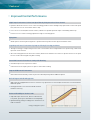
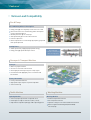
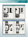
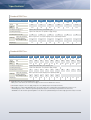
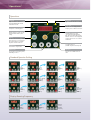
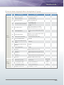
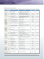
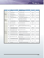
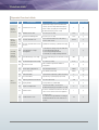
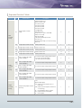
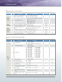
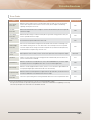
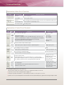
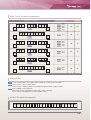
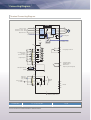
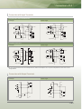
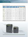
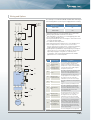
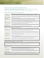
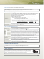
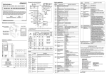
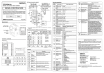
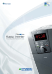
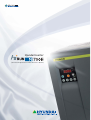
Hyundai Inverter
| The Controlling Solution of Powerful Inverter Brand |
▶
▶
▶
Hyundai’s Technology for the Best
High performance inverter for efficient business design
the best future with
series
▶
▶
▶
Series with Powerful Control Solution
|Excellent Applicability to Various Loads|
|Easy Maintenance & Simple Repair|
|High Reliability & Durability|
|Compliance with RoHS|
|Lower Audible Noise |
For the highest quality,
for the highest customer satisfaction
HYUNDAI N700E series inverter with high durability, elaborate speed controllability and
excellent torque responsibility provides superb operability.
The N700E’s compact size and sensorless vector control technology provide perfectly
optimized performance for industrial equipment.
Certificates of international standards (CE, UL/cUL) of N700E series make its
applications ready for global business.
Model Name Indication
Model Name Indication
N700E
L
F
�
Applicable
motor capacity
055 : 5.5kW
�
Series
name
055
Model Configuration
550 :55.0kW
Power source
L : 3-Phase, 220V
H : 3-Phase, 440V
With digital operator
Applicable motor
capacity(kW)
3-Phase, 220V
3-Phase, 440V
5.5
7.5
11
15
18.5
22
30
37
45
55
N700E-055LF
N700E-075LF
N700E-110LF
N700E-150LF
N700E-185LF
N700E-220LF
N700E-300HF
N700E-370HF
N700E-450HF
N700E-550HF
N700E-055LF
N700E-075LF
N700E-110LF
N700E-150LF
N700E-185LF
N700E-220LF
N700E-300HF
N700E-370HF
N700E-450HF
N700E-550HF
Contents
06 Features / 09 Dimensions / 10 Specifications
12 Operations / 13 Function Lists / 19 Protective Functions
20 Terminal Functions / 22 Connecting Diagram / 23 Connection to PLC
24 Wiring and Options / 26 For Correct Operation
|Features|
:
:Improved Control Performance
High Torque Performance in Ultra Low Speed Zone by Using Sensorless Vector Control
■ Hyundai’s advanced sensorless vector control technology provides a motor with high torque performance in ultra low speed
zone (Sensorless vector control: above 150% at 1Hz).
■ In case of fast acceleration/deceleration of motor, N700E series provides powerful torque controllability without trip.
■ Sensorless vector control technology expands the range of controlling speed.
Flying Start
■ N700E operates motors by detecting motor’s speed automatically when fan turns by natural wind or inertia
Superb Speed Control Performance by Improved Tuning Technology for Motors
■ Through technology of compensating the motor time constant while motor tuning minimizes the speed change, stable motor
operation can be achieved.
■ After auto-tuning operation for motor time constant, N700E series minimizes the controls of speed so that the rate of speed
variance can be reduced significantly while running.
Intensified Protective Functions for Safety while Running
■ Ground fault protection can prevent accidents.
■ Countermeasure for output’s phase loss protects motor while running.
Improved PID Control Performance
■ Built in PID function uniformly controls oil pressure and flow quantity without additional options.
Built-in Regenerative Braking System
■ BRD is basically equipped with the inverter so that the easy operation for acceleration/deceleration time is achieved without
additional options.
■ Driving performance of acceleration and deceleration
maximizes efficiency.
Enhanced Flexibility for Various Loads
■ Improved torque characteristic, which is reduced to the
1.7th power, perfectly fits with loads for fans and pumps.
■ Optimized energy saving according to the characteristics of
loads is achieved.
▶ Energy-saving by VP1.7 power
:
:Easy Operation and Maintenance
Various Inverter Display Functions
■ The operational status of the inverter are displayed on the monitor so that an user can understand the condition of the
inverter.
■ Cumulative hours of driving time and the actual running time are displayed for easy maintenance.
Compact Size
■ Compact size of N700E series utilizes conventional panel even when changing model.
■ N700E series has the same size with the N300 series so that there is no need of changing panel while changing inverter
models (5.5kW model excluded).
Convenient Maintenance and Repair
■ N700E is available to replace the fan without separation.
■ Fan on/off function increases fan’s durability and minimizes fan’s noise.
:
:Enhanced Compliance with Global Market Standard
Global Standard Certifications (CE, UL/cUL)
■ Range of input voltage expanded to 380~480V for global industrial environment.
■ Connection to the external signal is possible regardless of inverter types, SINK (PNP) or SOURCE (NPN), by setting control
terminals.
HYUNDAI INVERTER
06 07
|Features|
:
:Various Load Compatibility
Fan & Pump
Air Conditioning & Dust Collecting Fan
■ Energy saving by selecting torque characteristic of a load
■ Restart function in case of momentary power interruption
■ Factory automation by PLC
■ Machine protection by soft start/stop
■ Auto operation by precise PID control function
■ Low noise operation
■ Quick responsiveness to load change by frequency jump and
multi speed operation
Cooling Tower
■ Stable operation by supplying high qualified energy
■ Energy saving by speed and torque control
Water supply pump
Cooling water circulation pump
Boiler water supply pump
Conveyor & Transport Machine
Conveyor
■ Multi relay output terminal
■ Accurate acceleration & deceleration
■ Overweight prevention by using over-torque signal
■ Prevention of load slippage by curve acceleration and
deceleration
Factory Automation
■ Factory automation with PLC
■ High speed torque response to prevent slip down
■ Soft start and stop
Textile Machine
Washing Machine
Spinning Machine
Washing Machine
■ Soft start/stop for prevention of snap and cut off
■ Powerful torque boost function
■ Unit design for tough circumstances (dust, cotton)
■ Over torque limit function
■ Improvement of product quality by stable operating speed
■ Separate setting of acceleration and deceleration time
■ Built-in regenerative braking unit (below 22kW)
■ Soft start/stop
|Dimensions|
N700E-055LF/HF, 075LF/HF, 110LF/HF
N700E-150LF/HF, 185LF/HF, 220LF/HF
[Unit:mm]
[Unit:mm]
376
390
2-∅ 7
275
246
2-∅ 7
7
189
7
210
188
168
229
250
N700E-300HF, 370HF
N700E-450HF, 550HF
[Unit:mm]
312
265
240
4-∅ 10
270
342
300
510
530
2-12
2-10
312
142
158.5
280
2-∅ 12
520
548
142
[Unit:mm]
142
5.4
142
300
HYUNDAI INVERTER
08 09
|Specifications|
Standard 200V Class
055LF
075LF
110LF
150LF
185LF
220LF
Applicable Motor (4P, kW) 1)
5.5
7.5
11
15
18.5
22
Rated
Capacity
(kVA)
200V
8.3
11.1
15.6
22.2
26.3
31.2
240V
10.0
13.3
18.7
26.6
31.6
37.4
64
76
90
Inverter Model (N700E-□□□LF)
Rated Input Voltage (Vac)
3-phase (3line) 200~240V±10%, 50/60Hz±5%
Rated Output Voltage 2)
3-phase 200~240V (This corresponds to supply voltage)
24
Rated Output Current (A)
Regenerative Braking
Braking 3) Available Minimum
Value of Register (Ω)
32
45
Built-in regenerative circuit (Discharging resistor is optional) up to 22kW
Weight (kg)
17
17
17
8.7
6
6
4.2
4.5
4.5
6.5
7.5
8
Standard 400V Class
055HF
075HF
110HF
150HF
185HF
220HF
300HF
370HF
450HF
550HF
5.5
7.5
11
15
18.5
22
30
37
45
55
380V
7.9
10.5
15.1
21.1
25.0
29.6
38.2
49.4
59.2
72.4
480V
10.0
13.3
19.1
26.6
31.6
37.4
48.2
62.4
74.8
91.5
90
110
27
30
Inverter Model (N700E-□□□HF)
Applicable Motor (4P, kW)
Rated
Capacity
(kVA)
1)
Rated Input Voltage (Vac)
3-phase (3line) 380~480V±10%, 50/60Hz±5%
-
Rated Output Voltage
3-phase 380~480V (This corresponds to supply voltage)
-
2)
Rated Output Current (A)
Regenerative Braking
12
16
23
32
38
45
58
75
-
Built-in regenerative circuit (Discharging resistor is optional) up to 22kW
Braking 3) Available Minimum
Value of Register (Ω)
70
50
50
30
20
20
Weight (kg)
4.2
4.5
4.5
7
7
7.5
22
22
※ 1) Applicable motor represents HYUNDAI 3-phase motor.
When you use other motors, be cautious not to apply over rated current to N700E series inverter.
2) Rated output voltage decreases as supply voltage decreases (AVR option prevents this phenomenon).
3) When capacitor is regenerating, braking torque is the average torque value of single motor when maximum deceleration occurs.
But braking torque is not a continuous regenerating torque (average deceleration torque is dependent on the motor loss).
And N700E series has internal regenerating brake circuit. But use the optional braking resistor when a big regenerative torque is needed.
Standard 200V, 400V Class
Specification
Control Method
4)
Description
Space vector PWM method
Output Frequency Range 5)
0.01~400Hz
Frequency Accuracy 6)
Digital: Max frequency ±0.01%
Analogue: Max frequency ±0.1%
Frequency Resolution
Digital setting: 0.01 Hz (<100Hz), 0.1Hz (>100Hz)
Analogue: Max frequency / 500 (when DC 5V input), Max frequency / 1,000 (DC 0~10V, 4~20mA)
V/f Characteristic
Base frequency: 0~400Hz free set
Torque pattern selection available (constant torque / reduced torque)
Overload Capacity
150%, 1minute
Acceleration/Deceleration Time
0.1~3,000sec (linear/curve selection available)
2nd Acceleration/Deceleration setting available
DC Braking
Performs between min frequency and established braking frequency.
Level and time setting available
Input
Output
Frequency Standard Operator
Setting
External Signal
Set by volume up/down key.
1W, 1~2kΩ variable resistor.
DC 0~10V (input impedance 10kΩ), 4~20mA (input impedance 250Ω).
Forward
Standard Operator
Reverse
Start/Stop External Signal
Run key / Stop key (change forward/reverse by function command).
Forward run/stop, reverse run/stop set by terminal assignment (1a, 1b selection available)
Intelligent Input Terminal
FW (Forward), RV (Reverse),CF1~4 (Multi-speed), RS (Reset),
AT (Analog input current / voltage Transfer), USP (Unattended Start Protection),
EXT (External Trip), FRS (Free Run Stop), JG (Jogging Command), SFT (Software Lock Command),
2CH (2nd Acceleration/Deceleration), SET (2nd Motor Constants Setting)
Intelligent Output Terminal
RUN (Run Signal), FA1 [Frequency Arrival Signal (at the set frequency)],
FA2 [Frequency Arrival Signal (at or above the set frequency)], OL (Overload Advanced Notice Signal),
OD (Output Deviation of PID Signal), AL (Alarm Signal)
Frequency Monitor
Analog meter (DC0~10V full scale. Max. 1mA)
Analog output frequency signal and analog output current signal
Analog output voltage signal selection available.
Alarm Output Contact
OFF when inverter alarm (b contact output) / Auto switch ON and OFF /
Intelligent output terminal use available
Main Functions
Auto-tuning, AVR Function, V/F Setting, Curve Accel./Decel. Selection, Frequency Upper/Lower Limit, 6 Level
Multi-speed, Start Frequency Set, Carrier Frequency Setting (0.5~16kHz), PID Control, Frequency Jump, Analog
Gain Bias Control, Jogging Run, Electronic Thermal Level Control, Retry, Auto Torque Boost, Trip History
Monitor, Software Lock, S-shape Accel./Decel., Frequency Conversion Display, USP, 2nd Control
Protective Functions 7)
Over-current Protection, Overload (electronic thermal), Over-voltage, Communication Error,
Under-voltage, Output Short, USP Error, EEPROM Error, External Trip, Ground Fault, Temperature Trip
Environmental
Conditions
Options
Ambient Temperature
-10~50°C (over 40°C: set carrier frequency below 2.0kHz)
Storage Temperature
-20~60°C (while transporting: short time)
Ambient Humidity
Below 90%RH (non-condensing)
Vibration
5.9m/s2 (0.6G). 10~55Hz (JIS C0911 test methodology)
Location
Less than 1,000m above sea level, Indoor (no corrosive gas, no flammable gas, no oil-drop, no-dust)
Noise filter, DC reactor, AC reactor, Remote operator, Remote operator cable, Regenerative braking resistor
※ 4) Before control method setting A31 is set to 2 (sensorless vector control), the following instructions should be considered.
- Carrier frequency setting b11 should be above 2.1kHz.
- When you use motors below half capacity of max applicable motor capacity, it is hard to get sufficient quality.
- When over 2 motors are about to be operated, sensorless vector control cannot be applied.
5) When you operate motor over 50/60Hz, inquire about maximum available rotational number.
6) For the purpose of stable motor control, output frequency can exceed approximately 1.5kHz at [A04]
7) Protective method is based on JEM1030.
HYUNDAI INVERTER
10 11
|Operations|
Operations
PRG lamp
Run lamp
Light is on when the value is entering
Light is on when the inverter is
generating PWM output or RUN
command is entered.
▼
▼
▲
Hz/A lamp
Power lamp
▲
Show whether the displayed data is
frequency value or data current value.
Lamp for the controlling power
▲
Display (LED signal)
Stop/Reset key
Run key
Stop operating inverter and
cancellation of alarm(available in
both sides of operator and terminal)
When the inverter is run through b15
terminal, operator can select valid or
invalid state.
▲
Displays frequency, motor current,
motor rotational number, alarm
setting
▲
▶
Run the inverter. RUN key is disabled
when the inverter is selected to run
by terminal. RUN key is available
only while the above LED is on.
Volume key
Function key
Set output frequency.
(available only when the lamp is on)
▶
▲
▲
▲
Command selecting function.
Up/Down key
Store key
Increase/decrease frequency value,
and modify set values
Store the selected data or the set
value.
Standard Operator Setting
0.0
d
01
Push
FUNC key
once
--
A
2
01
Store data by
pushing
STR key
Push
key
twice
�
0.0
01
Push
FUNC key
once
A
01
060.0
Push
� key
9 times
Push
FUNC key
once
Push
key
4 times
�
F
Store data by
pushing
STR key
060.0
01
--
Push
FUNC key
once
Set frequency
by pushing
� key
d
Push
FUNC key
once
A
Display Running Frequency
F
01
Push
FUNC key
once
Push
key
5 times
�
0
F
A
Displays
current
running
frequency
01
Start
inverter by
pushing
RUN key
|Function Lists|
Monitor Modes (d-group) & Basic Setting Modes (F-group)
Main Function Code
Function Name
Description
d01
Output Frequency Monitor
0.00~400.0Hz (“Hz”LED on)
d02
Output Current Monitor
0.0~99.9A (“A”LED on)
d03
Output Voltage Monitor
Output voltage display (V)
Initial Data
Change Mode on Run
“F”: Forward direction,
d04
Motor Rotational Direction Monitor
“r” : Reverse direction,
“O”: Stop
Basic
Monitor
PID Feedback Monitor
d06
Terminal Input Monitor
d07
Terminal Output Monitor
d08
Frequency Conversion Monitor
0~99.99/100.0~400.0 (= d01 x b14)
d09
Power Consumption Monitor
0~9999 [W]
d10
d11
Basic
Setting
Display converted value (set to “A 50“)
d05
Cumulative Time Monitor During
RUN (Hr)
Cumulative Time Monitor During
RUN (Min)
Availabe when PID function is selected
Display the state of Intelligent input terminal
display
Display the state of intelligent input terminal
and alarm output terminals
0~9999 [Hr]
0~59 [Min]
d12
DC Link Voltage Monitor
0~999 [V]
d13
Trip Monitor
Displays the details of the last trip
d14
Trip Monitor 1
Display the details for the last 1 protective trip
d15
Trip Monitor 2
Display the details for the last 2 protective trips
d16
Trip Monitor 3
Display the details for the last 3 protective trips
d17
Trip Counter
Display the number of inverter trips
F01
Output Frequency Setting
0.00~400.0 [Hz]
F02
Accelerating Time Setting 1
0.0~999.9 / 1000~3000 [sec]
30.0sec
○
F03
Decelerating Time Setting 1
0.0~999.9 / 1000~3000 [sec]
30.0sec
○
F04
Driving Direction Selection
0--- forward / 1--- reverse
0
X
Initial volume
value
○
HYUNDAI INVERTER
12 13
|Function Lists|
Expanded Function A Mode
Main Function Code
Basic
Setting
Analog
Input
Setting
(External
Frequency
Setting)
Multilevel
and
Jogging
Setting
V/F
Characteristic
DC
Braking
Setting
Frequency
Related
Setting
Function Name
Description
Initial Data
Change Mode on Run
A01
Frequency Setting Method
(Multi-speed Setting)
0 (main volume) / 1 (control circuit terminal input) /
2 (standard operator) / 3 (remote operator)
0
Ⅹ
A02
Run Setting Method
0 (standard operator) / 1 (control circuit
terminal input) / 2 (remote operator)
0
Ⅹ
A03
Base Frequency Setting
Set base frequency from 0 to max by 0.01Hz unit
60.00Hz
Ⅹ
A04
Maximum Frequency
Maximum frequency can be set from base
frequency A03~400Hz by 0.1Hz unit.
60.00Hz
Ⅹ
A05
External Frequency Start Value
0~400Hz (0.01Hz unit)
0.00Hz
Ⅹ
A06
External Frequency End Value
0~400Hz (0.01Hz unit)
0.00Hz
Ⅹ
A07
External Frequency Start Value Ratio
0~100 (0.1% unit)
0.0%
Ⅹ
A08
External Frequency End Ratio
0~100 (0.1% unit)
100.0%
Ⅹ
A09
External Frequency Start Selection
0 (start from start frequency)
1 (start from 0Hz)
0
Ⅹ
A10
External Frequency Sampling
Set sampling number on analog input filter
from 1 to 8.
4
Ⅹ
A11
~
A25
Multi-speed Frequency
0.0~400Hz (0.01Hz unit)
-
○
A26
Jogging Frequency
0.5~10.0Hz (0.01Hz unit)
0.50Hz
○
A27
Selection of Jogging Stop Operation
0 (free-run stop) / 1 (stop by decelerating) /
2 (stop by DC braking)
0
Ⅹ
A28
Torque Boost Selection
0 (manual) / 1 (automatic)
0
Ⅹ
A29
Manual Torque Boost
Set voltage of manual torque boost.
1.0%
○
A30
Manual Torque Boost Frequency
Select frequency ratio out of base frequency
from 0~100%.
10.0%
○
A31
Control Method
0 (linear torque characteristic) / 1 (reduced torque
characteristic) / 2 (sensorless vector control)
0
Ⅹ
A32
Output Voltage Gain
20~110%
100.0%
○
A33
DC Braking Selection
0 (disabled) / 1 (enabled)
0
Ⅹ
A34
DC Braking Frequency
0.0~10.0Hz (0.01Hz unit)
0.50Hz
Ⅹ
A35
DC Braking Waiting Time
0.0~5.0sec (0.1sec unit)
0.0sec
Ⅹ
A36
DC Braking Force
0~50% (0.1% unit)
10.0%
Ⅹ
A37
DC Braking Time
0.0~10.0sec (0.1 sec)
0.0sec
Ⅹ
A38
Upper Limit of Frequency
A39~A04Hz (0.01Hz unit)
0.00Hz
Ⅹ
A39
Lower Limit of Frequency
0.00~A38Hz (0.01Hz unit)
0.00Hz
Ⅹ
A40
A42
A44
Frequency Jump
0.00~400Hz (0.01Hz unit)
0.00Hz
Ⅹ
A41
A43
A45
Frequency Jump Width
0.00~10.00Hz (0.01Hz unit)
0.00Hz
Ⅹ
Main Function Code
PID
Control
Setting
AVR
Related
Setting
2nd
Accel /Decel
Related
Functions
Function Name
Description
Initial Data
Change Mode on Run
0
Ⅹ
10.0%
○
A46
PID Selection
0 (disabled) / 1 (enabled)
A47
P (Proportion) Gain
0.1~100.0% (0.1 unit)
A48
I (Integration) Gain
0.0~100.0sec (0.1 unit)
10.0sec
○
A49
D (Differentiation) Gain
0.0~100.0sec (0.1 unit)
0.0sec
○
A50
PID Scale Ratio
0.1~1,000.0 (0.1 unit)
100.0
Ⅹ
A51
Feed-Back Input Method
0 (current input) / 1 (voltage input)
0
Ⅹ
A52
AVR Selection
0 (always ON) / 1 (always OFF) /
2 (OFF only when deceleration)
0
Ⅹ
A53
Motor Voltage Capacity
200 / 220 / 230 / 240 (200V class)
380 / 400 / 415 / 440 / 460 / 480 (400V class)
220V / 380V
Ⅹ
A54
2nd Acceleration Time
0.0~999.9/1,000~3,000sec
10.0sec
○
A55
2nd Deceleration Time
0.0~999.9/1,000~3,000sec
10.0sec
○
A56
2 Level Accel./Decel. Switching
Method Setting
0 (input from terminal [2CH]) / 1 (switching
frequency setting from acc / dec1 to acc / dec2)
0
Ⅹ
A57
Frequency Setting for Accel./Decel.
Time Switching in Acceleration
0.00-400.0Hz (0.01Hz unit)
0.00Hz
Ⅹ
A58
Frequency Setting for Accel./Decel.
Time Switching in Deceleration
0.00-400.0Hz (0.01Hz unit)
0.00Hz
Ⅹ
A59
Acceleration Pattern Selection
0 (linear) / 1 (S-curve) / 2 (U-curve)
0
Ⅹ
A60
Deceleration Pattern Selection
0 (linear) / 1 (S-curve) / 2 (U-curve)
0
Ⅹ
A61
Voltage Input (O) Offset Setting
Set voltage offset when external analog signal
input is entered..
0.0
○
A62
Voltage Input (O) Gain Setting
Set voltage gain when external analog signal
input is entered.
100.0
○
A63
Current Input (OI) Offset Setting
Set current offset gain when external analog
signal input is entered.
0.0
○
A64
Current Input (OI) Gain Setting
Set current gain when external analog signal
input is entered.
100.0
○
A65
FAN Setting
0 (always ON) / 1 (ON only when RUN)
0
Ⅹ
HYUNDAI INVERTER
14 15
|Function Lists|
Expanded Function b Mode
Main Function Code
Restart
Related
Functions
Electric
Thermal
Related
Functions
Overload
Limiting
Related
Functions
Other
Functions
Function Name
Description
Initial Data
Change Mode on Run
0
Ⅹ
b01
Instant Restart Selection
0 (alarm after trip) / 1 (start from 0Hz when
restart) / 2 (start from predefined frequency
when restart) / 3 (stop by decelerating from
predefined frequency when restart)
b02
Allowable Restart Time
0.3~1.0sec (0.1sec unit)
1.0sec
Ⅹ
b03
Instant Restart Waiting Time
0.3~3.0sec (0.1sec unit)
1.0sec
Ⅹ
b04
Electronic Thermal Level
Set electronic thermal level in 20~120% of
inverter rated current.
100.0%
Ⅹ
b05
Electronic Thermal Characteristic
Selection
0 [SUB(reduced torque)] / 1 [CRT(linear torque)]
1
Ⅹ
b06
Overload and Over-voltage
Limiting Mode
1. Overload, over-voltage restriction mode OFF
2. Overload limiting mode ON
3. Over-voltage limiting mode ON
4. Overload, over-voltage limiting mode ON
1
Ⅹ
b07
Overload Limiting Level Setting
Set overload limiting level in 20~200% of rated
current.
150%
Ⅹ
b08
Overload Limiting Constant Setting
0.1~10.0sec (0.1 unit)
0.1sec
Ⅹ
b09
Soft-lock Selection
Soft-lock makes operator be unable to
change data.
0
Ⅹ
b10
Start Frequnecy Adjustment
0.5~10.0Hz (0.01Hz unit)
0.50Hz
Ⅹ
b11
Carrier Frequency
0.5~15.0kHz (0.1kHz unit)
5.0kHz
O
b12
Initialization Mode
0 (initialization of trip data) / 1 (data initialization)
0
Ⅹ
b13
Select Initial Value
0 (for Korea) / 1 (for Europe) / 2 (for USA)
0
Ⅹ
b14
Frequency Conversion Coefficient
0.01~99.99 (0.01 unit)
1.00
○
b15
Stop Key Enable
0 (stop enable) / 1 (stop disable)
0
Ⅹ
b16
Stop Free-run Operation
0 (restart from 0Hz) / 1 (restart from
predefined frequency) / 2 (stop after free-run)
0
Ⅹ
b17
Communication
Set inverter communication code from 1~32 when
connect inverter with external control equipment
1
Ⅹ
Ground Fault Detection
0 : No detection
0.1~100.0%: Detect ground fault according to
the predefined ratio out of the rated inverter
current.
0.0
Ⅹ
b18
Expanded Function C Mode
Main Function Code
C01
Function Name
Intelligent Input Terminal 1
Setting
Input
Terminal
Setting
Description
FW (forward direction)
RV (reverse direction)
CF1 (multi-speed 1)
CF2 (multi-speed 2)
CF3 (multi-speed 3)
CF4 (multi-speed 4)
JG (jogging run)
SET (2nd control)
2CH (2-level accel/decel command)
FRS (free-run stop)
EXT (external trip)
USP (unattended start protection)
SFT (soft lock)
AT (analog input voltage / current transferring)
Initial Data
Change Mode on Run
0
Ⅹ
RS (reset)
Intput
Terminal
Status
Setting
C02
Intelligent Input Terminal 2 Setting
(Code) - Same as C01
1
Ⅹ
C03
Intelligent Input Terminal 3 Setting
(Code) - Same as C01
2
Ⅹ
C04
Intelligent Input Terminal 4 Setting
(Code) - Same as C01
3
Ⅹ
C05
Intelligent Input Terminal 5 Setting
(Code) - Same as C01
13
Ⅹ
C06
Intelligent Input Terminal 6 Setting
(Code) - Same as C01
14
Ⅹ
C07
Contact Setting of a/b of Input
Terminal 1 (NO/NC)
Set contacts of a/b of intelligent input terminal 1
0-a contacts (normal open) [NO]
1-b contacts (normal close) [NC]
0
Ⅹ
C08
Contact Setting of a/b of Input
Terminal 2 (NO/NC)
Set contacts of a/b of intelligent input terminal 2
0
Ⅹ
C09
Contact Setting of a/b of Input
Terminal 3 (NO/NC)
Set contacts of a/b of intelligent input terminal 3
0
Ⅹ
C10
Contact Setting of a/b of Input
Terminal 4 (NO/NC)
Set contacts of a/b of intelligent input terminal 4
0
Ⅹ
C11
Contact Setting of a/b of Input
Terminal 5 (NO/NC)
Set contacts of a/b of intelligent input terminal 5
0
Ⅹ
C12
Contact Setting of a/b of Input
Terminal 6 (NO/NC)
Set contacts of a/b of intelligent input terminal 6
0
Ⅹ
1
Ⅹ
(Code)
Output
Terminal
Setting
C13
Intelligent Relay Output Terminal
RN Setting
RUN (running signal)
FA1 [frequency arrival signal (at the set
frequency)]
FA2 [frequency arrival signal (at or above the
set frequency)]
OL (overload advanced notice signal)
OD (output deviation of PID signal)
AL (alarm signal)
HYUNDAI INVERTER
16 17
|Function Lists|
Expanded Function C Mode
Main Function Code
C14
Output
Terminal
Setting
Output
Terminal
Status Setting
Output
Terminal
Related
Setting
Function Name
a/b Contacts of Intelligent Relay
Output Terminal RN Setting
Description
A contacts (normal open) [NO]
B contacts (normal close) [NC]
Initial Data
Change Mode on Run
0
Ⅹ
0
Ⅹ
100.0%
○
0.0%
○
Sets the intelligent analog output terminal [FM]
(Code)
C15
Monitor Signal Selection
Monitors output frequency
Monitors output current
Monitors output voltage
C16
Adjustment of Analog Meter GAIN
0~250% (1% unit)
C17
Adjustment of Analog Meter OFFSET
-3.0-10.0% (0.1 unit)
C18
Overload Pre-warning Level
Setting
Sets the pre-warning level for overload in
50~200% of rated inverter current
100.0%
Ⅹ
C19
Arrival Frequency Setting (Acceleration)
0.00~400.0Hz (0.01Hz unit)
0.00Hz
Ⅹ
C20
Arrival Frequency Setting (Deceleration)
0.00~400.0Hz (0.01Hz unit)
0.00Hz
Ⅹ
C21
PID Deviation Level Setting
0.0~10.0% (0.1% unit)
1.0%
Ⅹ
Initial Data
Change Mode on Run
Motor Constant Setting H Mode
Main Function Code
Motor
Constant
Setting
Function Name
Description
H01
Auto-tuning Mode
0 : Auto-tuning OFF
1 : Auto-tuning ON (non-rotational mode)
0
Ⅹ
H02
Selection Motor Constant
0 : Standard data
1 : Auto-tuning data
0
Ⅹ
H03
Motor Capacity
0 : 220V / 2.2kW
1 : 220V / 3.7kW
2 : 220V / 5.5kW
3 : 220V / 7.5kW
4 : 220V / 11kW
5 : 220V / 15kW
6 : 220V / 18.5kW
7 : 220V / 22kW
8 : 220V / 30kW
9 : 380V / 2.2kW
10 : 380V / 3.7kW
-
Ⅹ
H04
Motor Pole Selection
2 / 4 / 6 / 8 poles (P)
4
Ⅹ
H05
Motor Rated Current
0.1 - 200.0A
-
Ⅹ
H06
Motor No-load Current Io
0.1 - 100.0A
-
Ⅹ
H07
Motor Rated Slip
0.01 - 10.0%
-
Ⅹ
H08
1st Resistor R1 for Motor Constant
Setting range : 0.001 - 30.00Ω
-
Ⅹ
H09
Overloaded Inductance Lsig for
Motor Constant
Setting range : 0.01 - 100.00mH
-
Ⅹ
H10
R1 Auto-tuning Data for Motor
Constant
Setting range : 0.001 - 30.00Ω
-
Ⅹ
H11
Lsig Auto-tuning Data for Motor
Constant
Setting range : 0.01 - 100.00mH
-
Ⅹ
11 : 380V / 5.5kW
12 : 380V / 7.5kW
13 : 380V / 11kW
14 : 380V / 15kW
15 : 380V / 18.5kW
16 : 380V / 22kW
17 : 380V / 30kW
18 : 380V / 37kW
19 : 380V / 45kW
20 : 380V / 55kW
21 : 380V / 75kW
|Protective Functions|
Error Codes
Name
Over-current
Protection
Description
Display on Digital Operator
When the inverter output is short circuited or motor shaft is locked, excessive current for the
inverter flows. To protect inverter from excessive current, inverter output is turned off by
E04
operating current protection circuit.
Overload
When an overload of motor is detected by the electronic thermal function, the inverter trips and
Protection
turns off its output.
Over-voltage
When the DC bus voltage exceeds a threshold, due to regenerative energy from the motor, the
Protection
inverter trips and turns off its output.
E05
E07
Communication
Error
An error between operator and inverter is detected.
E60
A decrease of internal DC bus voltage below a threshold results in a fault of controlling circuit.
Under-voltage
This condition can also generate excessive motor heat or cause low torque. The inverter trips and
Protection
turns off its output when the voltage is below 150~160V (200V class) or below 300~320V (400V class)
E09
An instantaneous interruption may cause this error.
Output Shortcircuit
USP Error
EEPROM Error
When outputs are short circuited, excessive current causes protection circuit to stop inverter output.
If power is on at the same time inverter is being operated in terminal mode, USP error will be seen
E04 or E34
E13
(in case of USP function is enabled).
When the external noise or temperature rise causes internal EEPROM error, an inverter output
E08
is turned off. Check the setting data because there is a case of alarm signal failure.
External Trip
Temperature Trip
When the external equipment makes a failure, inverter receives this failure signal and turns off
When the inverter internal temperature is higher than the specified value, the thermal sensor in
E21
the inverter module detects it and turns off the inverter output.
Ground Fault
Protection
E12
the output (Intelligent input terminal need to be set for this function).
The inverter is protected by the detection of ground faults between the inverter output and the motor.
E14
※ Protective functions protect inverter from over-current, over-voltage and under-voltage.
Once protective functions are operated, all outputs of inverter are disconnected and motor is stopped by free-run stop.
Inverter keeps this protective status until reset command is entered.
HYUNDAI INVERTER
18 19
|Terminal Functions|
Explanation of Main Circuit Terminals
Symbol
Terminal Name
Explanation of Content
R, S, T (L1, L2, L3)
Main Power
Connect input power.
U, V, W (T1, T2, T3)
Inverter Output
Connect 3-phase motor.
PD, P (+1, +)
DC Reactor
After removing the short bar between PD and P, connect DC reactor for improvement of power factor.
P, RB (+, B+)
External Braking Resistor
Connect optional external braking resistor.
G
Inverter Earth Terminals
Grounding terminal.
Explanation of Control Circuit Terminals
Signal
Symbol
P24
6 (RS)
5 (AT)
Input
Signal 1)
4 (CF2)
3 (CF1)
2 (RV)
Terminal Name
Power Terminal for Input Signal
Intelligent Input Terminal :
Forward Direction (FW), Reverse Direction (RV), Multi-speed 1-4 (CF1-4), 2-Level
Accel/Decel Command (2CH), Reset (RS), Free-run Stop (FRS), External Trip (EXT),
Soft Lock (SFT), Jogging Run (JG), Unattended Start Protection (USP) 2),
Analog Input Voltage / Current Transferring (AT)
1 (FW)
Explanation of Content
24VDC±10%, 35mA
Contact input :
Close : On (run)
Open : Off (stop)
Minimum on time:
over 12ms
CM1
Common Terminal for Input or Monitor Signal
FM
Output Frequency Meter, Output Current Meter, Output Voltage Meter
Analog frequency meter
H
Power Supply for Frequency Command
10VDC
O
Voltage Frequency Command Terminal
0~10VDC, input impedance 10Ω
OI
Current Frequency Command Terminal
4~20mA, input impedance 210Ω
L
Common Terminal for Frequency Command
Output
Signal 3)
RN0
RN1
Intelligent Output Terminal :
Running Signal (RUN), Frequency Arrival Signal (at the set frequency) (FA1),
Frequency Arrival Signal (at or above the set frequency) (FA2), Overload Advanced
Notice Signal (OL), Output Deviation of PID Signal (OD), Alarm Signal (AL)
Rated value for contact :
AC 250V 2.5A (resisitive load)
0.2A (Induced load)
DC 30V 3.0A (resisitive load)
0.7A (induced load)
Trip
Alarm
Output
Signal 4)
AL0
AL1
AL2
Alarm Output Signal :
at Normal Operation, Power Off (Initial Condition) : AL0-AL2 Closed
at Abnormal : AL0-AL1 Closed
Rated value for contact :
AC 250V 2.5A (resisitive load)
0.2A (induced load)
DC 30V 3.0A (resisitive load)
0.7A (induced load)
Monitor
Signal
Frequency
Setup
Signal
※ 1) Input signal terminals from 1 to 6 are contact “a”s.
When you want to change those terminals to contact “b”s, configuration should be set in C07~C12
2) USP: Protects inverter from restarting when power supply is on.
3) Intelligent relay output terminal RN is “a” contact. When you use RN as “b” contact, please set it to C14.
4) Operator can select ‘pre-warning alarm for overload’ and ‘arrival to the predefined frequency’ signals with the intelligent output terminal.
Main Circuit Terminal Arrangement
Main Circuit Terminal Block
R
S
T
PD
G
P
RB
U
V
W
G
Short bar
R
S
T
G
PD
P
RB
U
V
S
T
PD
G
P
S
T
PD
G
P
RB
U
V
W
G
RB
U
V
S
T
PD
G
P
G
N
U
V
G
S
T
PD
P
W
G
Short bar
R
M4
10.6
N700E - 110LF
M5
13
N700E
N700E
N700E
N700E
- 150LF
- 150HF
- 185HF
- 220HF
M5
13
N700E - 185LF
N700E - 220LF
M6
17
N700E - 300HF
N700E - 370HF
M6
17
N700E - 450HF
N700E - 550HF
M8
22
W
Short bar
R
- 055LF
- 075LF
- 055HF
- 075HF
- 110HF
N700E
N700E
N700E
N700E
N700E
G
Short bar
R
Width(mm)
W
Short bar
R
Screw Size
Corresponding Type
N
Short bar
U
V
W
G
Wiring Order
Step1 Connect 3 phase power to the power input terminals R, S and T shown in the figure
Step2 Connect inverter to the 3 phase motor :
Connect inverter output terminals U, V and W to the input terminal of 3 phase motor.
Step3 Connecting DC reactor (optional)
Connect DC reactor to P and PD terminals (DC reactor is optional).
Please remove shorting bar when connecting DC reactor.
Control Terminal Arrangement
DOP RXP RXN CM1 CM1 6 5 4 3 2 1 CM1 P24 H O OI L L FM CM1
RN0 RN1 AL0 AL1 AL2
HYUNDAI INVERTER
20 21
|Connecting Diagram|
Terminal Connecting Diagram
N700E
R
3-Phase Power
200V Class : 200 ~ 240V
400V Class : 380 ~ 480V
(50/60Hz ±10%)
S
Rectifier
Inverter
T
Power Circuit
Control Circuit
Signal
Line
Control
Circuit
U
T1
V
T2
W
T3
IM
PD
P
Shorting Bar
RB
P24V
Buit-in BRD Circuit
P24
AL1
1
AL2
2
Intelligent Input
Terminal
(6 Connections)
Relay Output Contacts
AL0
3
4
(Digital Input)
5
6
CM1
RN1
RN0
FM
FM Output Monitor
(PWM)
Intelligent Relay
Output Contacts
(Initial Value :
Frequency Arrival Signal)
CM1
H
Frequency
Controller
(1kΩ, 1W)
Current Input
4 ~ 20mA
DC 0 ~ 10V
O
10kΩ
OI
DC 4 ~ 20mA
P12V
Analog
Input
200Ω
L
DOP
RXP
RS485
RXN
CM1
G
Ground D (200V Class)
Ground C (400V Class)
Terminal Name
1, 2, 3, 4, 5, 6, P24, FM
H, O, OI
Common
CM1
L
※ Be careful as there are different kinds of common terminals.
|Connection to PLC|
Connection with Input Terminals
Using Interface Power Inside Inverter
■ Sink Type
■ Source Type
S
P24
P24
Short
PLC
S
DC 24V
PLC
Short
CM1
DC 24V
CM1
FW
1
8
8
COM
Output Module
Inverter
Output Module
Inverter
Using External Power
■ Sink Type
■ Source Type
COM
S
P24
PLC
P24
DC 24V PLC
DC 24V
CM1
DC 24V
CM1
COM
FW
1
8
8
DC 24V
S
Output Module
Inverter
Output Module
Inverter
※ Be sure to turn on the inverters after turning on the PLC and its external power source to prevent the parameters in the inverter from
being modified.
Connection with Output Terminals
■ Sink Type
■ Source Type
CM2
11
DC 24V
COM
12
11
COM
CM2
Inverter
12
DC 24V
PLC
Inverter
PLC
HYUNDAI INVERTER
22 23
|Wiring and Options|
Common Applicable Tools
Class
200V
Class
400V
Class
Applicable Tools
External Resistor
between
P and RB (mm2)
Screw Size
of Terminal
Torque
(N•m)
More than 6
6
M4
1.2
HBS60N
50A
HiMC32
N700E-075LF
More than 10
6
M4
1.2
HBS60N
50A
HiMC32
11
N700E-110LF
More than 16
6
M5
3.0
HBS100N
75A
HiMC50
15
N700E-150LF
More than 25
16
M5
3.0
HBS100N
100A
HiMC65
18.5
N700E-185LF
More than 30
16
M6
4.5
HBS225N
150A
HiMC80
22
N700E-220LF
More than 35
16
M6
4.5
HBS225N
150A
HiMC110
5.5
N700E-055HF
More than 4
4
M4
1.2
HBS30N
30A
HiMC18
7.5
N700E-075HF
More than 4
4
M4
1.2
HBS30N
30A
HiMC18
11
N700E-110HF
More than 6
6
M4
1.2
HBS60N
50A
HiMC32
15
N700E-150HF
More than 10
10
M5
3.0
HBS100N
50A
HiMC40
18.5
N700E-185HF
More than 16
10
M5
3.0
HBS100N
75A
HiMC40
22
N700E-220HF
More than 25
10
M5
3.0
HBS100N
75A
HiMC50
30
N700E-300HF
More than 25
-
M6
2.8
HBS100N
100A
HiMC65
37
N700E-370HF
More than 35
-
M6
2.8
HBS225N
100A
HiMC80
45
N700E-450HF
More than 35
-
M8
6.0
HBS225N
150A
HiMC110
55
N700E-550HF
More than 70
-
M8
6.0
HBS225N
175A
HiMC130
Motor
Output
(kW)
Inverter
Model
5.5
N700E-055LF
7.5
※ 1) Use 600V, 75°C copper wire.
Power
Cable (mm2) 1)
R,S,T,U,V,W,PD,P
Circuit Breaker
(MCCB)
Magnetic
Contactor (MC)
Wiring and Options
The sensitivity of circuit breaker (MCCB) should be differentiated by the
sums of wiring distances (inverter-power supply and inverter-motor).
Wiring
and
options
Three Phase
Power Supply
Wiring Distance
Sensitive Current(mA)
Under 100m
50
Under 300m
100
※ Applied wiring equipment represents HYUNDAI 3-phase 4-poles motor.
※ Braking capacity should be considered for circuit breaker.
※ When wiring distance is over 20m, there is need to apply large power cable.
MCCB
※ Use circuit breaker (MCCB) for safety.
※ Do not perform ON/OFF function of electromagnetic contactor while inverter
is in normal operating condition.
※ Use 0.75mm2 for alarm output contact.
※ When wiring with metal tube using CV line, there exists 30mA/km current.
(1)
※ IV line has high non-dielectric constant : current increases 8 times.
Therefore, 8 times greater sensitivity current , as shown in the table above,
should be applied. When wiring distance is over 100m, use CV line.
※ ON/OFF operation is prohibited at the output side by using electromagnetic
contactor. when it is necessary to apply electromagnetic contactor at the
output side by using bypass circuit, protective circuit that prevents
electromagnetic contactor from operating ON/OFF function should be
applied while inverter is in normal operation.
(2)
MC
Order
(1)
(3)
(4)
R
S
T
PD
Function Name
Description
Input-side AC Reactor
As a measure of suppressing harmonics induced
on the power supply lines, it is applied when
imbalance of the main power voltage exceeds 3%
(and power source capacity is more than 500kVA),
or when the power voltage is rapidly changed. It
also improves the power factor.
(Harmonic Control,
Electrical
Coordination, Powerfactor Improvement)
(2)
Noise Filter for
Inverter
This reduces common noise that is generated
between input power and ground. Connect
this filter to 1st side (input side) of inverter.
(3)
Radio Noise Filter
(Zero-phase Reactor)
Electrical noise interference may occur on
nearby equipment such as a radio receiver.
This magnetic choke filter helps reduce
radiated noise (can also be used on output).
(4)
Input Radio Noise
Filter
This reduces radiated noise from Input power
wirings.
(5)
DC Reactor
Suppresses harmonics generated by the inverter
(6)
Output-side Noise
Filter
This reduces radiated noise from wiring in
the inverter output side. This also reduces
wave fault to radio and TV, and it is used for
preventing malfunction of sensor and
measuring instruments.
(7)
Radio Noise Filter
(0-phase Reactor)
Electrical noise interference may occur on
nearby equipment such as a radio receiver.
This magnetic choke filter helps reduce
radiated noise (can also be used on input).
(8)
Output AC Reactor to
Reduce Vibration and
Prevent Thermal
Relay Misapplication
This reactor reduces the vibration in the motor
caused by the inverter’s switching waveforms,
by smoothing the waveforms to approximate
commercial power quality. When wiring from
the inverter to the motor is more than 10m in
length, inserting a reactor prevents thermal
relay’s malfunction by harmonic generated by
inverter’s high switching.
(9)
LCR Filter
Sine-wave shaping filter for the output side.
(5)
Inverter
P
RB
U
V
W
(6)
(7)
( 8, 9 )
Motor
HYUNDAI INVERTER
24 25
|For Correct Operation|
� Before use, be sure to read through the Instruction manual to insure proper use of the inverter.
� Note that the inverter requires electrical wiring; a trained specialist should carry out the wiring.
� The inverter in this catalogue is designed for general industrial applications. For special applications in fields such as aircraft, nuclear power,
transport, vehicles, clinics, and underwater equipment, please consult us in advance.
� For application in a facility where human life is involved or serious losses may occur, make sure to provide safety devices to avoid a serious accident.
� The inverter is intended for use with a three-phase AC motor. For use with a load other than this, please consult with us.
■ Application to Motors | Application to General-purpose Motors
Operating Frequency
The overspeed endurance of a general-purpose motor is 120% of the rated speed for 2minutes (JIS C4004). For operation at
higher than 60Hz, it is required to examine the allowable torque of the motor, useful life of bearings, noise, vibration, etc. In this
case, be sure to consult the motor manufacturer as the maximum allowable rpm differs depending on the motor capacity, etc.
Torque Characteristics
The torque characteristics of driving a general-purpose motor with an inverter differ from those of driving it using commercial
power (starting torque decreases in particular). Carefully check the load torque characteristic of a connected machine and the
driving torque characteristic of the motor.
Motor Loss and
Temperature Increase
An inverter-driven general-purpose motor heats up quickly at lower speeds. Consequently, the continuous torque level (output)
will decrease at lower motor speeds. Carefully check the torque characteristics and speed range requirements.
Noise
When run by an inverter, a general-purpose motor generates noise slightly greater than by commercial power.
Vibration
When run by an inverter at variable speeds, the motor may generate vibrations, especially because of (a) unbalance of the rotor
including a connected machine, or (b) resonance caused by the natural vibration frequency of a mechanical system. Particularly,
be careful of (c) when a machine previously fitted with a constant speed is operated at variable speed.
Vibration can be minimized by (1) avoiding resonance points by using the frequency jump function of the inverter, (2) using a tireshaped coupling, or (3) placing a rubber shock absorber under the motor base.
Power Transmission
Mechanism
Under continued, low-speed operation, oil lubrication can deteriorate in a power transmission mechanism with an oil type gear
box (gear motor) or transmission. Check with the motor manufacturer for the permissible range of continuous speed. To operate
at more than 60Hz, confirm the machine’s ability to withstand the centrifugal force generated.
■ Application to Motors | Application to Special Motors
Gear Motor
The allowable rotation range of continuous drive varies depending on the lubrication method or motor manufacturer
(Particularly in case of oil lubrication, pay attention to the low frequency range). Grease lubrication has no degradation of
lubrication ability even when the number of rotation decreases (Allowable frequency range: 6~120Hz).
Brake-equipped Motor
For use of a brake-equipped motor, power supply for braking operation should be separately prepared. Connect the braking power supply
to the primary side power of the inverter. Use brake operation (inverter stop) and free run stop (FRS) terminal to turn off inverter power.
Pole-change Motor
There are different kinds of pole-change motors (constant output characteristic type, constant torque characteristic type, etc.),
with different rated current values. In motor selection, check the maximum allowable current for each motor of a different pole
count. At the time of pole change, be sure to stop the motor.
Submersible Motor
The rated current of a submersible motor is significantly larger than that of the general-purpose motor. In inverter selection, be
sure to check the rated current of the motor.
Explosion-proof Motor
Inverter drive is not suitable for a safety-enhanced explosion-proof type motor. The inverter should be used in combination with
a pressure-proof and explosion-proof type of motor. ※ Explosion-proof verification is not available for N700E series.
Synchronous (MS) Motor /
High-speed (HFM) Motor
In most cases, the synchronous (MS) motor and the high-speed (HFM) motor are designed and manufactured to meet the
specifications suitable for a connected machine. As to proper inverter selection, consult the manufacturer.
Single-phase Motor
A single-phase motor is not suitable for variable-speed operation by an inverter drive. Therefore, use a three-phase motor.
■ Application to Motors | Application to the 400V-class Motor
A system applying a voltage-type PWM inverter with IGBT may have surge voltage at the motor terminals resulting from the cable constants including the
cable length and the cable laying method. Depending on the surge current magnification, the motor coil insulation may be degraded. In particular, when a 400V
class motor is used, a longer cable is used, and critical loss can occur. Take the following countermeasures : (1) install the LCR filter between the inverter and
the motor,(2) install the AC reactor between the inverter and the motor, or (3) enhance the insulation of the motor coil.
■ Notes on Use | Drive
Run/Stop
Run or stop of the inverter must be done with the keys on the operator panel or through the control circuit terminal.
Installing an electromagnetic contactor (Mg) should not be used as a switch of run/stop.
Emergency Motor Stop
When the protective function is operating or the power supply stops, the motor enters the free run stop state.
When emergency stop or protection of motor is required, use of a mechanical brake should be considered.
High-frequency Run
N700E series can be set up to 400Hz. However it is extremely dangerous for rotational speed of two-pole motor to reach up to approx
24,000rpm. Therefore, carefully make selection and settings after checking the mechanical strength of the motor and connected
machines. Consult the motor manufacturer when it is necessary to drive a standard (general-purpose) motor above 60Hz.
■ Notes on Use | Installation Location and Operating Environment
Avoid installation in areas of high temperature, excessive humidity, or easy condensation of dew, as well as areas that are dusty, subject to corrosive gases,
residue of grinding solution, or salt. Install the inverter away from direct sunlight in a well-ventilated room that is free of vibration.
The inverter can be operated in the ambient temperature range from -10°C to 50°C
■ Notes on Use | Main Power Supply
In the following examples involving a general-purpose inverter, a large peak current flows on the main power supply side, and could destroy the
converter module. When such situations are predictable or connected crucial device is required to meet high reliability, install an AC reactor
between the power supply and the inverter. Also, when influence of indirect lightning strike is possible, install a lightning arrester.
Installation of
an AC reactor
on the Input Side
A) The unbalance factor of the power supply is 3% or higher1.1)
B) The power supply capacity is at least 10 times greater than the inverter capacity (the power supply capacity is 500kVA or more).
C) Abrupt power supply changes are expected.
Examples) ① Several inverters are interconnected with a short bus.
② A thyristor converter and an inverter are interconnected with a short bus.
③ Junction and disjunction of installed phase advance capacitor.
In cases (A), (B) and (C), it is recommended to install an AC reactor on the main power supply side.
1) Example of how to calculate voltage unbalanced ratio. (voltage between lines on RS: VRS=205V, voltage between lines on ST : VST=201V,
voltage between lines on TR: VTR=200V), max voltage between lines-average between lines= VRS-(VRS+VST+VTR)/3=205-202
∙Voltage unbalanced ratio =
Using an Independent
Electric Power Plant
Max. voltage between lines - Average voltage between lines
Average voltage between lines
×100 =
VRS-(VRS+VST+VTR)/3
(VRS+VST+VTR)/3
×100 =
205-202
×100 = 1.5(%)
202
If an inverter is run by an independent electric power plant, harmonic current can cause to overheat the generator or distort
output voltage waves of the generator. Generally, the generator capacity should be five times that of the inverter (kVA) in a PWM
control system, or six times greater in a PAM control system.
■ Notes on Peripheral Equipment Selection
Wiring Connections
Electromagnetic
Contactor
Wiring
between
Inverter
and
Thermal Relay
Motor
(1) Be sure to connect main power wires with R (L1), S (L2), and T (L3) (input) terminals and motor wires to U (T1), V (T2), and
W (T3) terminals (output). (Incorrect connection will cause an immediate failure.)
(2) Be sure to provide a grounding connection with the ground terminal( )
When an electromagnetic contactor is installed between the inverter and the motor, do not perform on-off switching during running.
When used with standard output motors (standard three-phase squirrel cage four pole motors), the N700E series does not need
a thermal relay for motor protection due to the internal electronic protective circuit. A thermal relay, however, should be used:
during continuous running out of a range of 30Hz to 60Hz for motors exceeding the range of electronic thermal adjustment
(rated current). When several motors are driven by the same inverter, install a thermal relay for each motor. The RC value of the
thermal relay should be more than 1.1times the rated current of the motor. Where the wiring length is 10m or more, the
thermal relay tends to turn off readily. In this case, provide an AC reactor on the output side or use a current sensor.
Installing a Circuit Breaker
Install a circuit breaker on the main power input side to protect inverter wiring and ensure personal safety.
Choose a circuit breaker compatible with inverter.
Wiring Distance
The wiring distance between the inverter and the remote operator panel should be 20meters or less. When this distance is
exceeded, use CVD-E (current-voltage converter) or RCD-E (remote control device). Shielded cable should be used on the wiring.
Beware of voltage drops on main circuit wires (A large voltage drop reduces torque).
Earth Leakage Relay
If the earth leakage relay (or earth leakage breaker) is used, it should have a sensitivity level of 15mA or more (per inverter).
Leakage current is depending on the length of the cable.
Phase Advance Capacitor
Do not use a capacitor for improvement of power factor between the inverter and the motor because the high-frequency
components of the inverter output may overheat or damage the capacitor
■ High-frequency Noise and Leakage Current
(1) High-frequency components are included in the input/output of the inverter main circuit, and they may cause interference in a transmitter, radio, or sensor
if used near the inverter. The interference can be minimized by attaching noise filters (option) in the inverter.
(2) The switching of an inverter causes an increase of leakage current. Be sure to ground the inverter and the motor.
Because a DC bus capacitor deteriorates as it undergoes internal chemical reaction, it should normally be replaced every
five years. Be aware, however, that its life expectancy is considerably shorter when the inverter is subject to such adverse
factors as high temperatures or heavy loads exceeding the rated current of the inverter. The figure at the right shows the
approximate lifetime of the capacitor when it is used 24hours. Also, such moving parts as a cooling fan should be replaced.
Maintenance, inspection and replacing parts must be performed by only specified professional engineers.
Ambient Temperature( )
■ Lifetime of Primary Parts
Capacitor Lifetime(years)
HYUNDAI INVERTER
26 27
HHIS-WC-CE-B27-01, 2010. 3 Designed by JC Communication
www.hyundai-elec.com
Head Office
1 Jeonha-dong, Dong-gu, Ulsan, Korea
Tel: 82-52-202-8101~8
Fax: 82-52-202-8100
Seoul
(Sales & Marketing)
140-2, Gye-dong, Jongno-gu, Seoul, Korea
Tel: 82-2-746-7596, 8451, 7452
Fax: 82-2-746-8448
Orlando
3452 Lake Lynda Drive, Suite 170, Orlando, Florida 32817, U.S.A.
Tel: 1-407-249-7350
Fax: 1-407-275-4940
New Jersey
300 Sylvan Avenue, Englewood Cliffs, NJ, 07632, U.S.A.
Tel: 1-201-816-0286
Fax: 1-201-816-4083
London
2nd Floor, The Triangle, 5-17 Hammersmith Grove, London, W6 0LG, UK
Tel: 44-20-8741-0501
Fax: 44-20-8741-5620
Tokyo
8th Fl., Yurakucho Denki Bldg.1-7-1, Yuraku-cho, Chiyoda-gu, Tokyo, 100-0006, Japan
Tel: 81-3-3212-2076, 3215-7159
Fax: 81-3-3211-2093
Osaka
I-Room 5th Fl. Nagahori-Plaza Bldg. 2-4-8, Minami Senba, Chuo-Ku, Osaka, 542-0081, Japan
Tel: 81-6-6261-5766, 5767
Fax: 81-6-6261-5818
Dubai
Level 2, Unit 205, Emaar Square-Bldg.4, Sheikh Zayed Road, P.O.Box 252458, Dubai, U.A.E.
Tel: 971-4-425-7995
Fax: 971-4-425-7996
Sofia
1271, Sofia 41, Rojen Blvd., Bulgaria
Tel: 359-2-803-3200, 3220
Yangzhong
No.9 Xiandai Road, Xinba Scientific and Technologic Zone, Yangzhong, Jiangsu, P.R.C. Zip: 212212, China
Tel: 86-511-8842-0666, 0212
Fax: 86-511-8842-0668, 0231
Fax: 359-2-803-3203