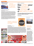
1
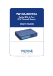
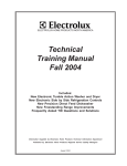
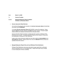
P R O D U C T S
S E R V I C E
EHP to Produce
Select CrosleyBrand Appliances
E
lectrolux Home Products was recently
awarded a contract to begin production
of select Crosley Brand appliances
this year. The model chart below indicates
the model numbers and product types that
EHP will produce - and that servicers will
see in the marketplace in the near future.
Service claims for these products are
to be submitted to ServiceBench in the
same manner that existing claims are submitted for other EHP repairwork.
"EHP is proud to be a supplier of Crosley
branded products," said John Carroll, EHP's
National Service Manager. "We are equally
proud to have our authorized servicer network available to assist consumers who
may call upon someone to provide service."
Crosley Model No.
Product Type
CRTE151AW
Refrigerator
CRTE151AQ
Refrigerator
CRTE171AW
Refrigerator
CRTE171AQ
Refrigerator
CRTE183AW
Refrigerator
CRTE183AQ
Refrigerator
CRTE187AS
Refrigerator
CRTE187AK
Refrigerator
CRTEICE
Icemaker
CDBE241AW
Dishwasher
CDBE241AB
Dishwasher
CDBE241AQ
Dishwasher
CDBE566AW
Dishwasher
CDBE566AB
Dishwasher
CDBE566AQ
Dishwasher
CDBE566AS
Dishwasher
VOLUME 24 / ISSUE 2
B U L L E T I N
Fallingwater Cycla-matic
®
R E P O R T
A
complete diagnosis has now been
run on the Frigidaire Cycla-matic
refrigerator that famed architect
Frank Lloyd Wright specified for the
unique home Fallingwater. Designed in
1939 for Pittsburgh business magnate
Edgar Kaufman, the home named is
now a museum visited by more than
140,000 people each year near Mill
Run, PA.
Ed Ebersole, of Ebersole Appliance
in Elizabethtown, Pa., took delivery of
the Cycla-matic CT150 over a month ago
and began the painstaking process of
determining exactly what would be
needed to repair the 1950’s era refrigerator.
“The most obvious defects were
cosmetic, the left handle of the unit is
missing, there is damage to the
escutcheon plates, and the paint finish
needs restoration. Trays and their covers are also missing from inside the
refrigerator and three of the four shelves
were broken,” Ebersole said.
Ed next worked through the
mechanical system. The main issue
here is the refrigeration system, which is
not working. It was evident that there
was a leak in the sealed system, and Ed
was able to narrow this down to a leak
in the food plate located in the refrigerator section of the unit.
Ed Young, EHP’s most experienced
engineer for historic Frigidaire units, discussed the problem with Ebersole.
“There is a dual system that uses a
plate in the freezer section and runs to
a plate that chills the refrigerator section. Both these plates are made of aluminum – and that’s the problem,” Young
said. “At some time in the past the unit
was periodically switched off – perhaps
when the Kaufmans closed the house
up for the winter.”
Photo courtesy of the Western Pennsylvania Conservancy
H O M E
“The plates were probably not wiped
dry when they defrosted – and over time
that moisture would have corroded the
surfaces of the plates. We know the
food plate has developed one leak
because of this; and if we fix this, there’s
no guarantee we won’t immediately
develop another. The only answer is to
replace the food plate and this is not an
item we are going to find that easily.”
EHP will search for a food plate for
a 1952 Cycla-matic CTI-150*. In the
meantime the missing cosmetic parts
will be specially fabricated and the
painted surface will be re-finished in
time for the unit to be back on display in
Fallingwater, by late March. - Mark Newell
*If you have any working parts for this unit,
please contact the author at 706.651.7116
or via email at [email protected]
FEBRUARY 2004
Electrolux‘Precision Wash’
“One of the Best Kept Secrets in Dishwashing”
Originated in Europe and adapted in North America, Frigidaire’s
patented ‘Precision Wash System’ from Electrolux Home ProductsNA, makes for one of the most energy-efficient dishwashers on
the market today. Here’s a look at why this system works so well.
I
n 1994, Zanussi-branded dishwashers employed a unique wash system which utilized twin spray arms
that offered the benefits of reduced
noise and water consumption. At that
time, EHP North America's development engineers recognized this system
as one that would meet the demands
of the North American market. They
adapted the system by enlarging the
tub capacity and tweaking wash and
water systems to meet minimum
energy use requirements, and in
1996 launched the Precision Wash
System: the Energy Star-compliant
system that today can be found in
most models of Electrolux Frigidaire
brand dishwashers in North America.
Alternating spray arms
The key to the Precision Wash
design is the unique alternating
spray arms and precise combinations
of heat, water, detergent, and time.
The current dishwasher wash system
employed by the appliance industry
blasts the dishes using two simultaneous high-pressure spray arms,
drains the dishwasher, fills it back
up and blasts some more until the
dishes are clean. This high-pressure
method can be noisy, wasteful, and
allow food to redeposit onto dishes.
cycle, compared to up to 2 gallons
per fill, or 10 gallons total, in a conventional system.
100% water filtration
The Precision Wash System also
saves water by collecting, filtering
and reusing 100% of the wash
water during the wash cycle. Most
systems filter wash water to some
extent, but because high-pressure
systems use high volumes of water,
their filters are unable to remove all
of the food particles. The unfiltered
food is continuously re-circulated,
creating a type of “soup,” which is
not a desirable cleaning medium.
90 seconds. This allows the detergent
to work to soften the food particles,
making it easier for the water to
remove them during the next 90second segment. With only one
wash arm energized at a time, less
water is used and less washing
noise is created. The system uses
only 1.2 gallons of water per fill, for
a total of 6 gallons per normal wash
The Precision Wash System
employs two spray arms that alternate, spraying a mixture of detergent
and water from the lower spray arm
and then the upper spray arm every
PAGE 2
The Precision
Wash System has
a full-size filter with
thousands of tiny
holes that can trap
even the smallest
food particles. With
the low-pressure, alternating arms,
the wash water has enough time to
pass through the filter before being
redistributed by the pump. Special
spray jets on the bottom of the
lower wash arm continuously clean
the surface area of the filter, ensuring
complete filtration. Finally, the system
employs a Smart Soil Sensor, which
checks the amount of food soil in
the water. The sensor adjusts the
wash cycle as needed to guarantee
clean dishes every time.
Keeps on saving
FEBRUARY 2004 SERVICE BULLETIN
continued on page 11
VOLUME 24, ISSUE 2
ANNOUNCEMENTS
Stacking Kit for new Frigidaire Washer / Dryer Set
Frigidaire has introduced a new electronic washer,
GLTF2070CS0 and electric dryer GLEQ942CS0. These
models DO NOT require an under counter top panel kit.
Minimum under counter height is 35¼ inches. To stack
the new electronic dryer or any stackable dryer with a
blade lint filter on the new electronic washer, order
stacking kit 134258400. This kit is non-interchangeable
with stacking kit 5303937141.
— by John Carroll, EHP National Service Manager
N
stacking kit
part number 134258400
Kenmore Chest Freezer - Sears Model No.13051
The enclosed literature for chest freezers with serial numbers WB32227332 through
WB32227491 reads ‘for revision 0’. This is incorrect and should read ‘for revision 1’
instead. Corrections to the part list are as follows:
Part Description
Compressor (EGU80HLCW)*
Compressor controller
Run capacitor
Correct Part Number
216784600
216649315
218909913
*R134A charge for this compressor is 312 grams (10.9oz) The serial plate is incorrect.
2004
VOLUME 24
RUNNING INDEX
G E N E R A L I N F O R M AT I O N
ISSUE / PAGE
Phone Numbers
Listing of Electrolux Phone and Fax Numbers
Web Sites
Web Sites for Service information and feedback
1/2
3/10
Announcements
2003 Service Manuals Available!
Stacking kit for new Frigidaire Washer / Dryer set
Kenmore Chest Freezer Literature - correction -
1
2
2
2
3
3
1/2
3/10
SERVICE SOLUTIONS
Dishwashers
Dishwasher Timer - Stalling in the Cycle
2
9
Freezers
Finish Flaking From Rust on Freezer Tubing
Upright Freezer ‘Basket Track Kit’
Manual Defrost Upright Freezer Tubing
External Condenser Kits
Upright Freezers with Basket Slides
Broken Shelf Support Stud on Upright Freezers
Determining the Difference Between ADC Kits
1
1
1
1
2
2
2
4
4
5
6
6
6
6
Range Products
Self-Cleaning Oven Doors: ‘Lock at Random’
Hot Surface Indicator Lights
2
2
4
5
Refrigerators
Frost Build-up on the Evaporator
New Ice & Water Dispenser Switch
In-Line Regulator Fix for Front Water Filters
Water Dispenser on Side-By-Side Refrigerators
Icemaker Fill Tube Change
New Evaporator Fan Motor
1
1
2
2
2
2
7
7
7
7
8
8
Top Load & Laundry Center Washer Mandate!
Fault Codes for New Look Washer & Dryer
1
1
8
9-11
Wet Products
VOLUME 24, ISSUE 2
Continued Service,
Continued Growth!
FEBRUARY 2004 SERVICE BULLETIN
ew business growth expectations
for Electrolux Home Products
remains high for 2004. Last year,
EHP produced one out of every four
‘white goods’ products sold in North
America alone. EHP’s continued success lies in part with the level of service
we provide to our consumers. The
EHP Authorized Servicer Network
plays a large role in this. Their continued
commitment to excellence has led to
an ever growing EHP consumer base.
In past columns I have spoken
about the expectations consumers
have today and the practical steps
you can take to meet and exceed
their expectations. You have seen the
pressures and demands are not just
limited to the appliance industry, but
all industries where service is
required after the sale. Therefore we
are challenged to keep consumers
confident that they have made a
smart choice and a good decision by
choosing EHP.
You will read in this month’s Service Bulletin about select products
produced by EHP for the Crosley
Corporation. These products are
ones you can service by using the
same parts our Authorized Part Distributors currently have in stock.
Only those products produced by
EHP are eligible to be serviced under
the standard warranty terms of our
agreement with the EHP Authorized
Network. This is just one example
where being a valued member of the
EHP Authorized Service Company is
positioning your business for future
growth.
Recognizing opportunity is the key
to continued success. Together, we
can build a progressive and successful relationship that will last far into
the future.
PAGE 3
SERVICE
SOLUTIONS
Self-Cleaning Oven Doors: ‘Lock at Random’
Problem:
Oven door locks at random. This may occur during bake cycle or even when the range is
not in use. Failure is often very intermittent and usually does not occur when the service
technician is present making an accurate diagnosis very difficult. Often the EOC and sensor
are replaced unnecessarily.
Cause:
There are three possible causes for this; 1. A defective EOC. 2. A defective switch on the
door latch/motor assembly. (or) 3. An internal short in the oven door light switch.
Solution:
1. Defective EOC. The software in the EOC could erroneously be initiating a locking
sequence without the clean function being selected. Also the contacts in the latching relay
on the EOC can short circuit or stick in the closed position. This is the least likely cause
of the problem.
2. Defective switches on door latch/motor assembly. This failure will only apply to
ranges that have two switches in the monitor circuit of the latch motor assembly. These
switches will be labeled Lock Switch A and Lock Switch B on the wiring diagram. On the
lock motor assembly switch A is the lower switch and switch B is the upper switch. The EOC
constantly monitors the condition (open or closed) of the microswitches and if the switch
contacts fail either open when they should be closed or vice versa, then the EOC will run
the lock motor to try to correct the condition. This will sometimes also result in a fault code
displayed on the EOC.
3. Internal short in oven door light switch. This is the most frequent cause of the intermittent nuisance locking of the oven door. On many models the oven light switch has two
independent electrical circuits. One set of contacts serves as an interrupt circuit to the
latch motor to prevent the motor from running if the door is open. The other set of contacts supplies line voltage to the oven lamp or oven lamp relay when the door is open.
There is a specific type of short circuit that can occur inside the body of the switch which
allows the voltage that would normally be supplied to the oven light circuit to bleed
through to the latch motor contacts and cause the motor to run. This failure is difficult to
diagnose unless you are present at the time of failure. There is one technique that can be
used to achieve an accurate diagnosis when this failure is suspected. Locate the wire on
the E4 or MDL terminal of the EOC this is usually a pink wire that comes from the oven
door light switch. Disconnect the wire and insulate the terminal with electrical tape.
Secure the wire so that it can not touch any other electrical components or short to
ground. With this wire disconnected and secured allow the customer to continue using the
range to see if the nuisance locking occurs again. If it does then there is no doubt that the
cause is an internal short in the body of the oven door light switch.
continued on next page
PAGE 4
FEBRUARY 2004 SERVICE BULLETIN
VOLUME 24, ISSUE 2
SERVICE
SOLUTIONS
Self-Cleaning Oven Doors: ‘Lock at Random’
-cont’d
Below is pictured a typical circuit in which this kind of failure can occur. You can see that L1 is present at the
lower left corner of the door switch common terminal. If the internal short occurs, L1 voltage is delivered to
the normally open contact pictured at the top right corner of the door switch diagram. This will cause the latch
motor to run.
Hot Surface Indicator Lights
Problem:
When you receive a complaint from a customer that the hot surface indicator lamp on their
smooth glass top range stays on after the cooktop has cooled down, you can be certain
that the problem is NOT in the surface element switch.
Solution:
The hot surface indicator light operates on an independent circuit that is not connected to
the element control switch. There is a separate set of contacts in the limiter on every element
that are used to turn the light on or off as required.
The terminals for these contacts often have one grey wire and one black wire connected
to them. To diagnose the internal contacts you must disconnect the power to the range,
disconnect either the grey or black wire, which ever is most convenient, and test for continuity
between the terminals of the limiter contacts. If the top is cold there should be no continuity.
The limiter is a non serviceable part . You must replace the entire element if the hot
surface light contacts have stuck closed.
VOLUME 24, ISSUE 2
FEBRUARY 2004 SERVICE BULLETIN
PAGE 5
SERVICE
SOLUTIONS
Upright Freezers with Basket Slides
Problem:
Baskets fall off basket slides in upright freezers.
Cause:
Too much weight in the basket.
Solution:
Install basket slide shim kit - Part Number 216950200.
Kit consists of the following: (2) shims, (6) screws, and the instruction sheet.
To install:
1. Remove the basket or baskets from the freezer to allow clearance to install shim.
2. Remove basket slide. Secure basket shim and basket track to freezer wall with the
screws provided in the kit.
3. Place basket or baskets on track and test.
Broken Shelf Support Stud on Upright Freezers
Problem:
Upright Manual Freezers with Broken Shelf Support Stud.
Cause:
Too much weight on shelf.
Solution:
Order shelf stud repair kit - Part Number 216950400. Kit
consists of (1) shelf support right hand, (1) shelf support
left hand, (1) reinforcement plate, (2) screws, and an
instruction sheet.
Determining the Difference Between ADC Kits
Problem:
Servicer confusion over two new ADC kits with different part numbers.
Cause:
Each ADC kit is for a unique application.
Solution:
Find the voltage rating on the refrigerator in question. Order the correct kit based on
your findings. The ADC II kit for 220 Volt 50-60 HZ refrigerators is part number
5303918305. The ADC II kit for 115 Volt 60 HZ refrigerators is part number
PAGE 6
FEBRUARY 2004 SERVICE BULLETIN
VOLUME 24, ISSUE 2
SERVICE
SOLUTIONS
In-Line Regulator Fix for Front Water Filters
Problem: Repeated leaking of front water filter.
Cause:
High water pressure.
Solution: We have found through testing, that water pressure in the 90 PSI and higher range has
caused repeated leaking of front water filters. The filter and its base can be replaced and
properly adjusted, however, after 4 to 6 months the filter starts to leak again. There is now
a in-line regulator that can be installed on the inlet side of the water filter. (See Picture)
The part number for the regulator is 241556001. The regulator will hold the pressure on
the filter and water system at 60 to 65 PSI with up to 150 PSI line pressure.
To install:
1. Remove the cover from the water lines going to the front filter.
2. Remove the inlet water line (Brown line on right hand side)
3. Push the water pressure regulator into the filter base inlet.
4. Reinstall the water line and cover.
The regulator needs to be installed on the
inlet side of the water filter as shown.
Water Dispenser on Side-by-Side Refrigerators
Problem: Dispenser does not operate unless you push in on the door switch on side by side
refrigerators with the two paddle dispenser.
Cause:
The freezer door liner is shifted toward the mullion or the freezer liner is slightly wider
than it should be in the front.
Solution: There is a service freezer light switch available with a longer actuator, that will allow the
contact set to close and complete the connection to the dispenser. The part number for
the switch is 241547901.
VOLUME 24, ISSUE 2
FEBRUARY 2004 SERVICE BULLETIN
PAGE 7
SERVICE
SOLUTIONS
Icemaker Fill Tube Change
Problem:
Water is running over the ice maker fill tube on side by
side and top mount freezer refrigerators. This causes ice to
build up on evaporator fan motors and along the right side
of evaporators.
Cause:
In some cases, water entering the refrigerator at 75 PSI
and higher will follow along the top of the fill tube. A small
amount of water will then spray out of the fill tube and run
down the liner behind the evaporator cover.
Solution:
The fill tube has been changed. The open top is now
shorter and comes back to a "V". This change is in addition
to the change called out in the May 2001service bulletin on
page 10. The two changes are giving us much better control of the water coming out of the fill tube and still allowing
for the open top to dry the fill tube to prevent freezing. The
part number of the new fill tube is 241523501.
New Evaporator Fan Motor
Problem:
Change to evaporator fan motor (part number 240563701).
Cause:
Part availability and suppy issues.
Solution:
The fan motor will change in service parts
from part number 240563701 to service kit
number 5303918304. The new kit will have
a standard evaporator fan motor, a new
rear fan motor mounting bracket and a
new wiring harness to connect the motor.
original fan motor
new fan motor
PAGE 8
FEBRUARY 2004 SERVICE BULLETIN
VOLUME 24, ISSUE 2
SERVICE
SOLUTIONS
Dishwasher Timer - Stalling in the Cycle
Problem: Mechanical dishwasher timers stalling or just not
completing the cycle. After talking with Servicers on
the phone, a number of timers have been changed
just to have the customer call back to say it is still not
working. To assist in finding the cause for this problem, here is a procedure you can follow that can help
find the cause for this complaint.
Solution: Before you make the trip to the customer’s home, it
would be a good idea to call them by phone and have
them start the dishwasher for you, so it can be getting
hot while you are on the way to the house. It will not
be necessary to have the dishwasher loaded with
dishes or detergent on this call. The dishwasher
needs to run for about 25 minutes. This will aid you in
checking this problem.
When you first arrive, determine from the customer
what cycle and options were set at the time of failure.
You will also need to know what position the timer
was in when it stalled and how long the timer stayed
at that location. Next check the water temperature at
the sink. This way you will know how hot the water
was when the customer started the dishwasher for
you.
With this information it is time to check the dishwasher. First to be checked is the heater and safety
thermostat; both of these are located and checked
from underneath. They are on the bottom left side of
the tub. Check the heater for continuity. You will, or
should, get a resistance reading on the heater. The
safety thermostat should just read closed. Next, reset
the controls and reposition the timer to just before the
location the customer found the timer when it had
stalled. After setting the timer and the option switch,
make sure power is going to the heater to heat the
Thermostat Name
Temp Assure
Temp boost
Sanitize
High Temp Wash
VOLUME 24, ISSUE 2
Part number
154227805
154227806
154227807
154227808
Setting
117° ± 5.5°
127° ± 5.5°
137° ± 5.5°
122° ± 5.5°
water. Once this all has been done, check the temperature of the water in the tub. The timer should
advance on into the stall. You now need to wait until
the temperature rises in the tub to close the control
thermostat. The control thermostat is located under
the tub to the right side behind the junction box.
Shown below is a chart that lists the different control
thermostats currently used on dishwashers. This
chart shows the temperature settings of the different
thermostats as well as the temperature of the water in
the tub. Water is heated in the dishwasher by falling
back onto the heater as it is being sprayed inside the
tub. The temperature of the water will raise about one
degree every four minutes. As the water falls back
onto the heater, then onto the tub, the thermostat
senses this change in temperature. If you can watch
the water temperature without opening the door you
can follow this temperature rise. Once the water temperature has reached the proper temperature the
control thermostat should close to advance the timer.
If the thermostat does not close, take a jumper wire
and carefully short across the control thermostat to
see if the timer then advances. If the timer only
advances after shorting across the control thermostat, replace this thermostat.
If you replace the control thermostat you should add
thermo mastic to the head of the new part before
installing into tub. This will give you a better contact
between the thermostat and the tub. When mounting
the new thermostat into the tub, make sure it is good
and tight in the mounting hole.
If the timer does not advance after the thermostat is
shorted out, check the wires from the thermostat to
the selector switch; then on to the timer to make sure
you have all good tight connections. The control thermostat
only controls the timer motor in
Tub Temperature
the delay cycle; a loose con127° ± 5°
nection can keep the timer from
137° ± 5°
advancing.
147° ± 5°
132° ± 5°
FEBRUARY 2004 SERVICE BULLETIN
PAGE 9
ELECTROLUX
PHONE
NUMBERS
Name
Reason For Call
Phone Number
Fax Number
Customer Care
Center
Any Consumer Issue
706-860-4110
706-651-7135
Credit Department
Balance on Account
Need Invoice
614-825-0849
614-781-9312
Damage Claim Center
Return Authorization
Damage Claims
Damage Allowances
800-456-4669
(Option 1)
706-651-7715
Dealer / Distributor
Allowances
800-456-4669
(Option 2)
706-651-7054
National Locator
Parts, Service, Dealer,
Manuals
800-444-4944
Parts Department
Parts Questions
800-599-7569
(Option 2)
706-869-9096
706-228-4598
Product Specialist
(DDPS)
Product Exchange
800-456-4669
(Option 2)
706-651-7135
Servicer Assistance
Center (SAC)
Wiring Diagram
Technical Feedback
Territory Manager
Pay Increase
Technical
Specifications
Service Contract
NOTE: This information
is also available
by logging onto
ServiceBench.com
or Frigidaire.com
Contact Status
Number
Type
Model/Serial Number
Expiration Date
Full Coverage
Deductible
Warranty
NOTE: This information
is also available
by logging onto
ServiceBench.com
PAGE 10
888-842-3660
option 1 warranty administration
option 2 for refrigerators, freezers,
air conditioners or dehumidifiers
option 3 for cooking
option 4 for laundry or dishwashers
888-842-3660
(Option 1)
706-651-7735
888-842-3660
(Option 1)
706-651-7735
FEBRUARY 2004 SERVICE BULLETIN
VOLUME 24, ISSUE 2
Precision Wash System cont’d
Additional unique features
help to make this one of the quietest and most energy-efficient
dishwashers on the market. One
pump and motor (both smaller
than industry standards) are used
for washing purposes and another
(even smaller set) for draining the
tub. Since only one wash arm at a
time is energized, a smaller, more
efficient motor and pump is utilized. This system lowers motor
and splash noise, and reduces
energy consumption. The one-
piece door design eliminates the
gap between the door and access
panel found on many competitive
models, thus improving the aesthetics and lowering operational
noise levels even more.
Burner Box, Cooktop, EOC & Switch Access Diagram
Refer to the steps listed here when servicing all 2004 Frigidaire slide-in and drop-in gas ranges
1.
2.
3.
4.
5.
6.
7.
8.
9.
10.
11.
12.
13.
14.
15.
16.
Shut off gas to range.
Disconnect power.
Remove gas supply line at the regulator.
If necessary, carefully move range out of
the cabinet opening.
Remove grates and burner caps.
Inspect burners.
Remove screws securing burner skirts.
Inspect the electrode for cleanliness, etc.
Note: The electrode cannot be removed
from orifice holder assembly.
Remove knobs.
Remove flange nut.
Remove control panel.
Remove switch mounting plate screws.
Remove 2 screws from front shield on
each side panel.
Remove 5 screws from front shield and
4 screws from vent trim to be able to
remove console.
Remove machine screw on manifold side
range securing manifold to cooktop.
Remove cooktop assembly from unit.
Remove screws all around mounting plate
element located under cooktop assembly.
Remove glass assembly from burner box.
To reassemble cooktop, reverse procedures.
Ef fective March 1st 2004
All warranty claims must be submitted no later
than 60 days* after completion of service.
*Claims not submitted within this time frame will be rejected. If you have any
questions please contact the Service Assistance Center at 888-842-3660 Option 1.
VOLUME 24, ISSUE 2
FEBRUARY 2004 SERVICE BULLETIN
PAGE 11