1
www.conairnet.com
USER GUIDE
UGC028-1105
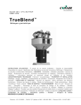
Positive
Displacement Pump
Models PD 3, 5, 7.5, 10, 15 and 25
Corporate Office: 412.312.6000 l Instant Access 24/7 (Parts and Service): 800.458.1960 l Parts and Service: 814.437.6861
Please record your equipment’s
model and serial number(s) and
the date you received it in the
spaces provided.
It’s a good idea to record the model and serial number(s) of your equipment and
the date you received it in the User Guide. Our service department uses this information, along with the manual number, to provide help for the specific equipment
you installed.
Please keep this User Guide and all manuals, engineering prints and parts lists
together for documentation of your equipment.
Date:
Manual Number: UGC028-1105
Serial Number(s):
Model Number(s):
DISCLAIMER: The Conair Group, Inc., shall not be liable for errors contained in this User Guide or
for incidental, consequential damages in connection with the furnishing, performance or use of
this information. Conair makes no warranty of any kind with regard to this information, including,
but not limited to the implied warranties of merchantability and fitness for a particular purpose.
Copyright 2005 l The Conair Group l All rights reserved
Ta b l e o f C o n t e n t s
1
Introduction
ATTENTION: Read this so no one gets hurt . . . . . . . . . . . . . . . . . . . . 1
Description . . . . . . . . . . . . . . . . . . . . . . . . . . . . . . . . . . . . . . . . . . . . . 2
Optional Sound Enclosures . . . . . . . . . . . . . . . . . . . . . . . . . . . . . . . . . 2
2
Te c h n i c a l S p e c i f i c a t i o n s
Positive displacement pump . . . . . . . . . . . . . . . . . . . . . . . . . . . . . . . .3
Pumps with sound enclosures . . . . . . . . . . . . . . . . . . . . . . . . . . . . . . 3
3
Installation
Installing the pump. . . . . . . . . . . . . . . . . . . . . . . . . . . . . . . . . . . . . . . 4
Installation and operation note . . . . . . . . . . . . . . . . . . . . . . . . . . . . . . 4
4
Maintenance
Preventative maintenance schedule . . . . . . . . . . . . . . . . . . . . . . . . . . 5
Inspect the vacuum relief valve . . . . . . . . . . . . . . . . . . . . . . . . . . . . . 5
Clean the vacuum relief valve. . . . . . . . . . . . . . . . . . . . . . . . . . . . . . . 5
Readjusting the vacuum relief valve . . . . . . . . . . . . . . . . . . . . . . . . . . 5
A
Appendix
We’re here to help . . . . . . . . . . . . . . . . . . . . . . . . . . . . . . . . . . . . . A-1
How to contact customer service . . . . . . . . . . . . . . . . . . . . . . . . . . A-1
Before you call... . . . . . . . . . . . . . . . . . . . . . . . . . . . . . . . . . . . . . . A-1
Equipment guarantee . . . . . . . . . . . . . . . . . . . . . . . . . . . . . . . . . . A-2
Performance warranty . . . . . . . . . . . . . . . . . . . . . . . . . . . . . . . . . . A-2
Ta b l e o f C o n t e n t s l i
AT T E N T I O N :
Read this so no one gets hurt
We design equipment with the user’s safety in mind. You can avoid the potential hazards
identified on this machine by following the procedures outlined below and elsewhere in the
User Guide.
WARNING: Improper installation, operation or servicing
may result in equipment damage or personal injury.
This equipment should be installed, adjusted, and serviced by qualified
technical personnel who are familiar with the construction, operation and
potential hazards of this type of machine.
All wiring, disconnects and fuses should be installed by qualified electrical technicians in accordance with electrical codes in your region.
Always maintain a safe ground. Do not operate the equipment at power
levels other than what is specified on the the machine serial tag and
data plate.
WARNING: Voltage hazard
This equipment is powered by three-phase alternating current, as specified on the machine serial tag and data plate.
Always disconnect and lock out the incoming main power source before
performing non-standard operating procedures, such as routine maintenance. Only qualified personnel should perform troubleshooting procedures that require access to the electrical enclosure while power is on.
1 l Introduction
Description
Conair Positive Displacement Vacuum Pumps are designed for long distance, high-volume material
conveying applications.
Each model has a powerful, rotating lobe-type blower, protected by a vacuum relief valve (factoryset to 12 in. Hg) and belt driven by a three-phase motor with magnetic starter and overload protection. An integrated pump protection filter is included and all components are mounted on a rugged
frame, housing an integrated exhaust muffler.
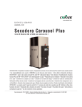
An optional sound enclosure may be added to reduce noise when installed near plant personnel.
O p t i o n a l s o u n d e n cl o s u r e s
Positive Displacement Pumps provide the strongest vacuum power available, but when operated for
long periods at high performance levels, noise should be abated if the pump is located near personnel. Sound Enclosures are available for all pump models and provide maximum noise control with
minimal space and allows easy access to pump maintenance areas.
Sound enclosures include externally mounted protection filter, vacuum gauge and filter gauge; 8 ft
exhaust stack (for noise); and easy access, tool-free front door.
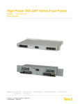
5 HP Pumps in
Sound Enclosures
(with dust collectors)
Super Quiet Sound
Enclosure (with
Dust Collector)
Introduction l 2
SPECIFICATIONS: POSITIVE DISPLACEMENT PUMP
Vacuum
Inlet
H
Exhaust
D
W
MODEL
PD3
Motor Type*
TEFC
Performance characteristics
Horsepower
3
Standard CFM at material
pickup point @ 10" Hg
52.6
Average sound level (dbA)
@ 8", 10" and 12" Hg
86
Dimensions in. {mm}
Standard inlet line size (OD) 1.5 {38}
Exhaust line size (OD)
2.5 {64}
Height (H)
37 {940}
Width (W)
35 {889}
Depth (D)
27 {686}
Installed Weight lb {kg} 325 {147}
Voltage Full Load Amps
240 V/3 phase/50-60 hz
7.6
480 V/3 phase/50-60 hz
3.8
575 V/3 phase/50
2.9
PD5
TEFC
PD7.5
TEFC
PD10
TEFC
PD15
TEFC
PD25
TEFC
5
7.5
10
15
25
76.6
121.2
154.5
201.1
346.2
86.3
86
85.8
88.8
93
3.0 {76}
4.0 {102}
51 {1295}
39.5 {1003}
33 {838}
640 {290}
4.0 {102}
4.0 {102}
52 {1321}
39.5 {1003}
34 {864}
960 {435}
39
19.5
16
59
29.5
27
1.75 {44}
2.5 {64}
37 {940}
35 {889}
27 {686}
325 {147}
2.25 {57}
2.5 {64}
2.5 {64}
4.0 {102}
41 {1041} 51 {1295}
35 {889} 39.5 {1003}
27 {686}
33 {838}
370 {168} 625 {283}
12
6
4.8
18.8
9.4
7.5
28
14
10.7
SPECIFICATIONS: PUMPS WITH SOUND ENCLOSURES
V
V
Vacuum Inlet
Service
V
V
Starter
Vacuum Gauge
3, 5, 7.5 HP
Super Quiet
10, 15, 25 HP
Specifications not listed below are the same as those listed above. All Sound Enclosures include a cooling fan 115 VAC @ 2 amps.
MODEL
PD3
PD5
PD7.5
Performance characteristics
Average sound level (dbA)
61.9
69.8
76.2
@ 8", 10" and 12" Hg
Enclosure Construction
Painted Steel
Allowance Space for
48 (Opposite Vacuum Inlet)
service access - inches
Dimensions in. {mm}
Height (H)
49 {1245}
Width (W)
54 {1372}
Depth (D)
32 {813}
3 l Te c h n i c a l S p e c i f i c a t i o n s
PD10
PD15
PD25
SUPER (ANY MODEL)
79.3
86.0
90.0
Under 60 dbA
Natural Aluminum
Painted Steel
36 (Opposite Vacuum Inlet)
36 (Front, Next to Filter)
64 {1626}
55 {1397}
36 {914}
96 {2438}
70 {1778}
50 {1270}
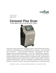
Installing the pump
1 Set or mount the vacuum pump in any convenient location.
2 Connect power. Refer to the accompanying wiring diagram for connection of the main power
supply and the conveying control circuit. IMPORTANT: You must provide a wall-mounted
disconnect for three-phase electrical connection. Incoming voltage and current must match
the electrical specifications on the pump data plate and serial tag.
WARNING: This equipment should be installed, adjusted, and serviced by qualified technical personnel who are familiar with the construction, operation and potential hazards of
this type of machine. All wiring, disconnects and fuses should be installed by qualified
electrical technicians in accordance with electrical codes in your region. Always maintain
a safe ground. Do not operate the equipment at power levels other than what is specified
on the the machine serial tag and data plate.
3 Check for proper rotation of the pump after power has been connected and before
operation.
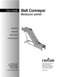
4 Install vacuum lines to loader stations and the dust collector.
5 Connect the dust collector vacuum outlet to the pump inlet.
Central
Vacuum Line
Positive
Displacement
Vacuum Pump
Material
Inlet
Material
Receivers
Receiving
Hoppers
Central Dust Collector
INSTALLATION AND OPERATION NOTE:
The pump inlet is equipped with a vacuum relief valve to prevent the
vacuum from exceeding 12 in. Hg. Excessive vacuum will reduce the
life of the pump and can destroy it.
For special applications requiring a higher vacuum level, consult
Conair service.
Installation l 4
Preventative Maintenance Schedule
To maintain the best performance, you should follow the maintenance recommendations outlined
here and in any included manuals from component manufacturers.
● Weekly, or as often as needed
❒ Check and clean the pump inlet filter.
An inlet filter has been provided to protect the pump from solid material that can enter and
damage the pump impellers. Material can enter the vacuum line if a loader filter is improperly installed or if if has a hole in it. Replace the pump inlet filter if it is torn or worn.
❒ Check all V/belts.
The V/belts have a tendency to stretch, so an adjustable motor base is provided. Keep belts
tight to prevent slippage and wear. Do not use belt dressings.
● Every 500 hours of operation
❒ Grease the pump.
Use No. 2 bearing grease or the equivalent. Refer to manuals from the component manufacturer for additional information and instructions.
● Every 1500 hours of operation
❒ Change the oil.
The vacuum pump has been filled with the proper oil and tested by Conair before shipment.
Even so, this oil should be changed periodically. Use SAE 40 regular or an equivalent oil.
● Every three months
❒ Check motor bearings and grease, if necessary.
The motor is equipped with double-shielded ball bearings having sufficient grease to last
indefinitely under normal service. But if the motor is used constantly in dirty, wet or corrosive atmospheres, you should add 1/4 oz. of grease per bearing every three months. Use
a quality, rust-inhibiting, polyure-based grease such as Chevron SRI. Refer to the motor
manual for additional instructions.
● Every six months
❒ Check the vacuum relief valve for proper operation.
The vacuum relief valve is designed to protect the pump from damage if the conveying line
becomes clogged or obstructed.
5 l Maintenance
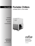
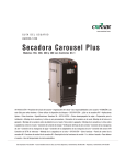
I n s p e c t t h e va c u u m r e l i e f va l v e
The vacuum relief valve is designed to protect the pump from damage if the conveying line
becomes clogged or obstructed. To check the valve:
1 Remove the inlet hose on the inlet filter housing.
2 Partially obstruct the inlet by using a rigid flat plate and slide it across the opening until 12
inches Hg registers on the gauge. Do NOT completely block the inlet. The relief valve should
open at approximately 12 inches Hg. Do not exceed 15 inches Hg. If the valve does not
release at or below 15 inches Hg, replace the valve.
✐
3
Note: Gauges should be checked/calibrated every 12 months.
Reconnect the hose to the inlet of the pump.
C l e a n t h e va c u u m r e l i e f va l v e
1 Stop the vacuum pump, disconnect and lockout the main power to the pump.
WARNING: High voltage. Always stop the Positive Displacement Pump,
disconnect and lock out the main power source before troubleshooting
or performing repairs.
2 Thoroughly inspect the vacuum relief valve. Check inside and out for any signs of contamination, residue or other foreign substances that may potentially block the motion of the internal,
spring loaded diaphragm.
3 Clean the inner components of the valve. Use a cleaning agent that will dissolve any plasticizer or oily build-up on the surfaces of the vacuum relief valve. Be sure to clean between the
vacuum relief diaphragm and its seat. Spray the cleaning agent into the valve opening and then
flush out. The valve may require disassembly to reach critical areas.
CAUTION: Wear eye protection. If you use compressed air to clean the equipment, you
must wear eye protection and observe all OSHA and other safety regulations pertaining
to the use of compressed air.
IMPORTANT: If a valve can not be cleaned adequately it should be replaced to prevent malfunction or a
potentially hazardous condition due to inadequate vacuum relief.
4 Reassemble the valve and re-adjust to the proper vacuum setting (see instructions for
adjusting the vacuum relief valve on the next page. )
Maintenance l 6
R e a d j u s t i n g t h e va c u u m r e l i e f va l v e
1 Prior to checking the vacuum relief valve operation, confirm the operation of the vacuum
gauge on the pump. With the pump off, the gauge should read "0" inches of mercury (Hg).
The gauge should rise to a range between 5 and 15 inches of Hg as the pump runs. If it does not
operate accordingly, replace the gauge. Vacuum gauges are not repairable.
2 Disconnect the flex hose from the inlet of pump protection filter.
3 Access the vacuum adjustment screw. Remove the threaded cap from the vacuum relief valve
to allow to access the vacuum adjustment screw.
4 Start the vacuum pump.
5 Open the relief valve. Position a rigid flat plate partially over the pump's air inlet with the pump
running until the relief valve opens as indicated by an inrush of air into the valve. Note the reading on the vacuum gauge. The exact point at which the valve opens to allow air to be sucked
into the pump should be 12 inches Hg.
6 Establish the proper vacuum relief point. With a screw driver, turn the adjustment screw to
establish the proper vacuum relief point while restricting the opening at the vacuum inlet of the
pump. Repeat the procedure until you feel air entering the relief valve and vacuum reading is 12
inch Hg on the vacuum gauge - max vacuum limit is 15 inch Hg.
7 Replace the adjustment screw cap and reconnect the flex hose to the inlet of pump.
7 l Maintenance
We ’ r e H e r e t o H e l p
Conair has made the largest investment in customer support in the plastics industry. Our service experts are available to help with any problem you might have
installing and operating your equipment. Your Conair sales representative also
can help analyze the nature of your problem, assuring that it did not result from
misapplication or improper use.
Additional manuals and prints for
your Conair equipment may be
ordered through the Customer
Service or Parts Department for a
nominal fee.
How to Contact Customer Service
To contact Customer Service personnel, call:
✐
NOTE:
Normal operating hours are 8:00 AM - 5:00 PM. After hours emergency
service is available at the same phone number.
From outside the United States, call: 814-437-6861
You can commission Conair service personnel to provide on-site service by contacting the Customer Service Department. Standard rates include an on-site hourly
rate, with a one-day minimum plus expenses.
B e f o r e Yo u C a l l . . .
If you do have a problem, please complete the following checklist before
calling Conair:
❒ Make sure you have all model, control type from the serial tag, and parts list
numbers for your particular equipment. Service personnel will need this information to assist you.
❒ Make sure power is supplied to the equipment.
❒ Make sure that all connectors and wires within and between control systems
and related components have been installed correctly.
❒ Check the troubleshooting guide of this manual for a solution.
❒ Thoroughly examine the instruction manual(s) for associated equipment, especially controls. Each manual may have its own troubleshooting guide to help
you.
❒ Check that the equipment has been operated as described in this manual.
❒ Check accompanying schematic drawings for information on special considerations.
Appendix l A-1
Equipment Guarantee
Conair guarantees the machinery and equipment on this order, for a period as
defined in the quotation from date of shipment, against defects in material and
workmanship under the normal use and service for which it was recommended
(except for parts that are typically replaced after normal usage, such as filters,
liner plates, etc.). Conair’s guarantee is limited to replacing, at our option, the part
or parts determined by us to be defective after examination. The customer assumes
the cost of transportation of the part or parts to and from the factory.
Pe r f o r m a n c e Wa r r a n t y
Conair warrants that this equipment will perform at or above the ratings stated in
specific quotations covering the equipment or as detailed in engineering specifications, provided the equipment is applied, installed, operated and maintained in the
recommended manner as outlined in our quotation or specifications.
Should performance not meet warranted levels, Conair at its discretion will
exercise one of the following options:
• Inspect the equipment and perform alterations or adjustments to satisfy
performance claims. (Charges for such inspections and corrections will be
waived unless failure to meet warranty is due to misapplication, improper
installation, poor maintenance practices or improper operation.)
• Replace the original equipment with other Conair equipment that will meet
original performance claims at no extra cost to the customer.
• Refund the invoiced cost to the customer. Credit is subject to prior notice by the
customer at which time a Return Goods Authorization Number (RGA) will be
issued by Conair’s Service Department. Returned equipment must be well crated
and in proper operating condition, including all parts. Returns must be prepaid.
Purchaser must notify Conair in writing of any claim and provide a customer receipt
and other evidence that a claim is being made.
Wa r r a n t y L i m i t a t i o n s
Except for the Equipment Guarantee and Performance Warranty stated
above, Conair disclaims all other warranties with respect to the equipment,
express or implied, arising by operation of law, course of dealing, usage of
trade or otherwise, including but not limited to the implied warranties of
merchantability and fitness for a particular purpose.
A-2 l Appendix