1
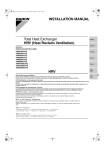
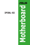
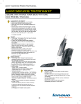
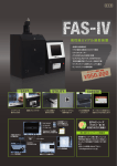
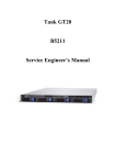
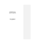
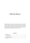
HP technical support
> HP Pavilion Elite m9000t CTO Desktop PC
Motherboard Specifications, IPIBL-LA (Berkeley)
Support details
» Motherboard specifications table
» Motherboard layout and photos
» Clearing the BIOS settings
» Clearing the BIOS password
Motherboard specifications table
Part / Feature
Specification / Support
Motherboard
description
CPU/Processor
Motherboard manufacturer's name: ASUS IPIBL-LA
HP/Compaq name: Berkeley-GL8E
Socket: 775
Supports the following processors:
Intel Core 2 Quad Q6xx0 with Quad Core technology up to
Q6600 (Kentsfield core)
Core 2 Duo E6x00 up to E6850 or E6700 (Conroe core)
Core 2 Duo E4x00 up to E4400 (Conroe core)
Front-side bus
(FSB)
800 MHz, 1066 MHz, 1333 MHz (processor dependent)
Chipset
Northbridge: Intel G33
Southbridge: ICH9R
System BIOS core brand: Award
Keyboard combination to used to enter BIOS: F10
Form factor
Micro-ATX: 9.6 in X 9.6 in
Memory
Dual channel memory architecture
Four 240-pin DDR2 DIMM sockets
Supported DIMM types:
DDR2-800
DDR2-667
Non-ECC memory only, unbuffered
Supports 2 GB DDR2 DIMMs
Supports 8 GB on 64 bit PCs
Supports 4 GB* on 32 bit PCs
BIOS features
NOTE:*Actual available memory may be less
Expansion slots
Video graphics
One PCI
One PCI Express x16 graphics (for a graphics card)
Two PCI Express x1 (for cards such as network, sound, tv-tuner)
Integrated graphics using Intel GMA 3100
Also supports PCI Express x16 graphics cards*
NOTE:*Either integrated graphics or the PCI Express x16 slot are
usable at one time; they are not usable concurrently.
Serial ATA
Six SATA connectors:
Supports 1 SATA-150 or SATA-300 disk drive on each SATA
connector
Speed up to 1.5Gb/sec or 3.0Gb/sec, complying with SATA
1.0 and SATA 2.0 specifications
NOTE:The faster rate of 3.0Gb/sec requires that both the hard drive
and the motherboard support it. If one or the other does not
support 3.0 Gb/sec, the PC negotiates down to the slower 1.5
Gb/sec.
RAID
Intel Matrix Storage Technology
Onboard RAID controller: ICH9R
All Berkeley models ship RAID-ready
Set up RAID using the included WinXP applet
RAID modes supported*:
RAID 0
RAID 1
NOTE:*RAID 5 requires three HDDs and RAID 10 requires four
HDDs. While this motherboard can support RAID 5 and 10,
only RAID 0 and RAID 1 modes are supported.
Onboard audio
High Definition 7.1 channel audio
Audio CODEC: Realtek ALC888S
Onboard LAN
One Intel 825662DC 10/100/1000 Mb/s (Gigabit Ethernet) Integrated
LAN
Onboard USB
USB 2.0
Twelve ports total
Four connectors on back panel
six headers (four 1x4 and two 2x5 USB headers) support eight
additional USB ports/devices
NOTE:Some USB ports may not be available externally for customer
use. For more information, see model specifications.
Onboard 1394
Back panel I/0
Internal
connectors
Type: IEEE 1394a 400Mb/s
Agere LFW3227 controller chip
Two ports total
One port on back panel
One header on motherboard supporting one additional port/device
One PS/2 mouse port (green)
One PS/2 keyboard port (purple)
One Coaxial S/PDIF input
One Coaxial S/PDIF output
One VGA port
Four USB 2.0
One 6-pin IEEE 1394a
One RJ-45 networking port
Six audio ports:
Line-in (light blue)
Microphone-in (pink)
Line-out (lime)
Center/Subwoofer-out (yellow-orange)
Side speaker-out (gray)
Rear speaker-out (black)
One 24-pin ATX power connector
One 4-pin ATX power connector
Six SATA connectors
One floppy drive connector
Two 12v fan connector for CPU fan and PC fan
One 9-pin header for power button, reset button, power LED, and
HDD LED
Three USB 2.0 headers supporting six USB ports or devices.
One IEEE 1394a header
One SPDIF-Audio output connector
One 4-pin audio line-input connector (interrupts line input on back
panel, Vista capable, requires matching front audio jack module)
One 9-pin audio header for headphone-out and microphone-in
(yellow, Vista capable, requires matching front audio jack module)
One Intel high-definition Audio/Modem Link (2x8 HDMI connector)
One jumper for resetting BIOS settings
One jumper to disable BIOS password checking
NOTE: Motherboard specifications are subject to change without notice.
Back to top
Motherboard layout and photos
Figure 1: layout
Figure 2: Photograph
Figure 3: Backplate
1 - PS/2 mouse port (green). This port is for a PS/2 mouse.
2 - Coaxial SPDIF Out port. This port connects an external audio output device via a coaxial SPDIF
cable.
3 - LAN (RJ-45) port. This port allows connection to a Local Area Network (LAN) through a network
hub.
4 - Rear Speaker Out port (black). This port connects to the rear speakers on a 4-channel, 6-channel, or
8-channel audio configuration.
5 - Center/Subwoofer port (yellow orange). This port connects the center/subwoofer speakers.
6 - Line In port (light blue). This port connects a tape, CD, DVD player or other audio sources.
7 - Line Out port (lime). This port connects a headphone or a speaker. In 4-channel, 6-channel, and 8channel mode, the function of this port becomes Front Speaker Out.
8 - Microphone port (pink). This port connects a microphone.
9 - Side Speaker Out port (gray). This port connects to the side speakers in an 8-channel audio
configuration.
10 - USB 2.0 ports 1, 2, 3, and 4. These four 4-pin Universal Serial Bus (USB) ports are available for
connecting USB 2.0 devices.
11 - IEEE 1394a port. This 6-pin IEEE 1394a port provides high-speed connectivity for audio/video
devices, storage peripherals, PCs, or portable devices.
12 - Video Graphics Adapter port. This 15-pin port is for a VGA monitor or other VGA-compatible
devices.
13 - Coaxial SPDIF In port. This port connects an external audio input device via a coaxial SPDIF cable.
14 - PS/2 keyboard port (purple). This port is for a PS/2 keyboard.
Back to top
Clearing the BIOS settings
CAUTION:Do not change any jumper setting while the computer is on. Damage to
the motherboard can result.
This motherboard has jumper to clear the Real Time Clock (RTC) RAM in CMOS. In the default
(normal) position the jumper is on pins 4-6.
Figure 4: Jumper location
Clearing CMOS
To clear CMOS, follow these steps:
1. Temporarily set jumper CLEAR_CMOS to pins 2-4.
2. Wait 5-10 seconds and then return the jumper to pins 4-6.
3. When you startup the PC you will need to enter BIOS setup to reset any custom
BIOS settings.
Clearing the BIOS password
The BIOS password is used to protect BIOS settings from unwanted changes. If the BIOS
password has been forgotten, disable password checking to enter setup and change or
erase the password.
To erase the BIOS password follow these steps:
1. Turn OFF the computer and unplug the power cord.
2. Locate the jumper labeled CLEAR_PWD. In the default (normal) position the jumper
is on pins 3-5.
3. Move the jumper on jumper CLEAR_PWD to pins 1-3 to clear password.
4. Plug the power cord and turn ON the computer.
5. Hold down the F10 key during the startup process and enter BIOS setup to change
or clear the password.
6. After changing or clearing the BIOS passwords, remember to reset the jumper to pins
3-5.
Back to top
SPI Header
The motherboard may include an SPI header. This header is used during manufacturing and
testing.
The header will have pins 1-2 bridged and should not be changed.
Back to top
Other solutions customers found helpful
» -- Updating the BIOS (HP and Compaq Desktop PCs & Workstations)
» HP and Compaq Desktop PCs -- Upgrading Memory (RAM)
» HP and Compaq Desktop PCs -- Obtaining Software and Drivers
» HP and Compaq Desktop PCs -- Upgrading or Replacing the Processor
Share this page
© 2009 Hewlett-Packard Development Company, L.P.
Search
Contact HP