1
V6
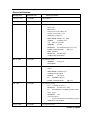
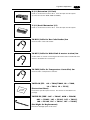
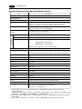
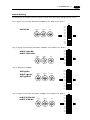
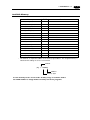
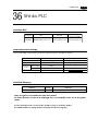
Record of Revision
Printing Date
Reference No.
Revised Contents
February, 1998
2021NE0
(First Edition)
February, 1999
2021NE0a
(Second Edition)
January,1999
2021NE0b
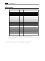
[A partial revision]
Matrix type
Multi-Link 2
Temperature Control Network
Change model names of V6
CBM printer supported
MITSUBISHI FX2N series, QnH
OMRON
SYSMAC CS1
A,B
Micro Logix1000
SIEMENS
KEYENCE
S7-200
KZ-A500 CPU Port, KV series
FATEK AUTOMATION
IDEC MICRO3
FB series
MODICON
Modbus RTU
YAMATAKE MX 200/50
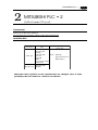
March, 2000
2021NE1
[A partial revision]
SIEMENS
S5 PG port
TAIANTP02
November, 2000
2021NE2
[A partial revision]
V606i
MITSUBISHI QnH CPU port
YOKOGAWA FA-M3R
OMRON
CS1 DNA
LG
MKX00S CPU port
FATEK AUTOMATION
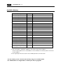
July, 2001
2021NE3
FB series
[A partial revision]
Koyo SU/SG(K-Sequence)
KEYENCE
KV700 seriese CPU
LG
MASTER-KxxxS CNET, GLOFA CNET
SAIA PCD
MOELLER
PS4
Automationdirect
Direct LOGIC,Direct LOGIC(K-Sequence)
CE Marking and UL Mark
August, 2002
2021NE4
[A partial revision]
Printed in Japan
Preface
Thank you for selecting the MONITOUCH V6 series.
For proper set-up, you are requested to read through this booklet to understand more
about the product.
For more information about V6 series, refer to the Reference Manual.
For further details about the PLC, see the manual attached to each PLC.
Notes:
1. This booklet may not, in whole or in part, be printed or reproduced without the prior written consent of Hakko Electronics Co.,
Ltd.
2. Information in this booklet is subject to change without prior
notice.
3. This booklet is intended to give information about MONITOUCH
hardware.
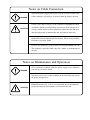
Notes on safe usage of MONITOUCH
In this "Hardware Specifications", you will find various notes categorized under the following
three levels with the signal words "Danger," "Warning," and "Caution."
These signal words are to warn the user of possible misuse of the unit. To comprehend the
critical notes on the safe procedure, you must go through this manual before you install
MONITOUCH and operate it correctly.
Danger
DANGER
indicates an imminently hazardous situation which, if not
avoided, will result in death or serious injury.
Warning
WARNING
indicates a potentially hazardous situation which, if not
avoided, could result in death or serious injury.
Caution
CAUTION
indicates a potentially hazardous situation which, if not
avoided, may result in minor or moderate injury and could
cause property damage.
Notes on System Design
WARNING
CAUTION
Never use the input function of MONITOUCH such as the touch switch
for an emergency switch because it could threaten a human life or
break a part of the unit.
Please design the system of the unit in order to respond to a malfunction
of the touch switch.
Never bundle input/output cables with high-voltage and large-current
cables such as power supply cables. Keep input/output cables at least
200mm away from power supply cables in order to avoid malfunction
caused by noise.
As for the use in the facilities related to nuclear energy or in the facilities
of official importance, please consult with our distributer about it.
Notes on Installation
Operate MONITOUCH under the conditions indicated by the manual.
CAUTION
If you don't set the conditions indicated by the manual for the unit, it
could cause fire, malfunction, physical damage or deterioration.
Maintain the following conditions in order to avoid fire or trouble.
Don't let the unit come in contact with corrosive gas, flammable
gas, solvents, grinding fluids or cutting oil.
Never let the unit be exposed to high temperature, high humidity,
and other outside weather conditions.
Don't allow the unit to be exposed to excessive dust, salt, and
metallic particles.
Don't allow the unit to be shaken or hit by other objects.
Equipment must be correctly mounted so that the main terminal will
not inadvertently be touched during an application.
Notes on Cable Connection
DANGER
CAUTION
Turn off the power supply when you set up the system or connect the
cables, otherwise you will get an electric shock or damage the unit.
Connect the cables correctly to the terminals of MONITOUCH in
accordance with the specified voltage and wattage. Over-voltage, overwattage and the incorrect cable connection could cause the unit to be
damaged physically or functionally and also could result in fire.
Ground FG terminal which must be for the unit. The level of grounding
resistance is less than 100Ω.
Prevent any conductive particles from entering into MONITOUCH.
The conductive particles could cause fire, trouble, or malfunction of
the unit.
Notes on Maintenance and Operation
DANGER
Never touch the terminals while the power supply is on, otherwise
you will get an electric shock.
You must put the cover of the terminals on the unit when you turn on
the power and operate it.
CAUTION
Hakko Electronics Co., Ltd. is not responsible for an unauthorized
person who may fix, disassemble, or reconstruct any unit.
Contents
1. Hardware Specifications
1. Special Features ............................................................................................................ 1-1
2. Notes on Usage ............................................................................................................. 1-2
3. System Composition ..................................................................................................... 1-4
4. Names of Components ................................................................................................ 1-10
5. Dimensions and Panel Cut-out ................................................................................... 1-12
6. Mounting Procedure .................................................................................................... 1-17
7. Wiring ......................................................................................................................... 1-18
8. Specifications .............................................................................................................. 1-20
9. Serial Connector (CN1) ................................................................................................ 1-26
10. Setting of Dip Switches ............................................................................................. 1-28
11. Modular Jack 1 & 2 .................................................................................................. 1-29
12. Bar Code Reader Interface ........................................................................................ 1-30
13. Printer Interface (CN2) .............................................................................................. 1-31
14. Video Interface .......................................................................................................... 1-32
15. Connection ................................................................................................................ 1-33
16. Operation of V6 Main Menu ...................................................................................... 1-38
17. Function Switches ..................................................................................................... 1-49
2. Connection to Link Units
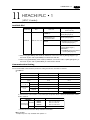
1. MITSUBISHI PLC • 1 ..................................................................................................... 2-1
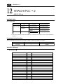
2. MITSUBISHI PLC • 2 ..................................................................................................... 2-7
3. MITSUBISHI PLC • 3 ................................................................................................... 2-11
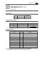
4. MITSUBISHI PLC • 4 ................................................................................................... 2-13
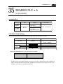
5. MITSUBISHI PLC • 5 ................................................................................................... 2-17
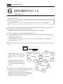
6. MITSUBISHI PLC • 6 ................................................................................................... 2-20
7. OMRON PLC • 1 .......................................................................................................... 2-22
8. OMRON PLC • 2 .......................................................................................................... 2-27
9. Sharp PLC • 1 ............................................................................................................. 2-28
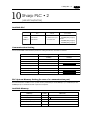
10. Sharp PLC • 2 ........................................................................................................... 2-31
11. HITACHI PLC • 1 ....................................................................................................... 2-33
12. HITACHI PLC • 2 ....................................................................................................... 2-36
13. Matsushita PLC ......................................................................................................... 2-39
14. YOKOGAWA PLC • 1 .................................................................................................. 2-42
15. YOKOGAWA PLC • 2 .................................................................................................. 2-44
16. YASKAWA PLC • 1 ..................................................................................................... 2-47
17. YASKAWA PLC • 2 ..................................................................................................... 2-50
18. TOYOPUC PLC .......................................................................................................... 2-52
19. FUJI PLC • 1 ............................................................................................................. 2-55
20. FUJI PLC • 2 ............................................................................................................. 2-58
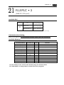
21. FUJI PLC • 3 ............................................................................................................. 2-61
22. FUJI PLC • 4 ............................................................................................................. 2-63
23.
24.
25.
26.
27.
28.
29.
30.
31.
32.
33.
34.
35.
36.
37.
38.
39.
40.
41.
42.
43.
44.
45.
46.
47.
48.
49.
50.
51.
Koyo PLC ................................................................................................................... 2-65
Allen-Bradley PLC • 1 ................................................................................................ 2-70
Allen-Bradley PLC • 2 ................................................................................................ 2-75
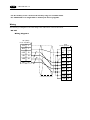
GE Fanuc PLC • 1 ..................................................................................................... 2-79
GE Fanuc PLC • 2 ..................................................................................................... 2-81
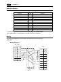
TOSHIBA PLC ........................................................................................................... 2-83
TOSHIBA MACHINE PLC ........................................................................................... 2-85
SIEMENS PLC • 1 ...................................................................................................... 2-87
SIEMENS PLC • 2 ...................................................................................................... 2-89
SIEMENS PLC • 3 ...................................................................................................... 2-91
SIEMENS PLC • 4 ...................................................................................................... 2-93
SIEMENS PLC • 5 ...................................................................................................... 2-95
SIEMENS PLC • 6 ...................................................................................................... 2-97
Shinko PLC ............................................................................................................... 2-99
SAMSUNG PLC ........................................................................................................ 2-101
KEYENCE PLC • 1 ................................................................................................... 2-103
KEYENCE PLC • 2 ................................................................................................... 2-105
KEYENCE PLC • 3 ................................................................................................... 2-108
LG PLC .................................................................................................................... 2-110
FANUC PLC ............................................................................................................. 2-115
FATEK AUTOMATION PLC ...................................................................................... 2-117
IDEC PLC ................................................................................................................ 2-119
MODICON PLC ........................................................................................................ 2-121
YAMATAKE PLC ...................................................................................................... 2-123
TAIAN PLC .............................................................................................................. 2-125
SAIA PLC ................................................................................................................. 2-127
MOELLER PLC ........................................................................................................ 2-129
Telemecanique PLC ................................................................................................. 2-130
Automationdirect PLC ............................................................................................. 2-132
Hardware
Specifications
1. Special Features
2. Notes on Usage
3. System Composition
4. Names of Components
5. Dimensions and Panel Cut-out
6. Mounting Procedure
7. Wiring
8. Specifications
9. Serial Connector (CN1)
10. Setting of Dip Switches
11. Modular Jack 1 & 2
12. Bar Code Reader Interface
13. Printer Interface (CN2)
14. Video Interface
15. Connection
16. Operation of V6 Main Menu
17. Function Switches
1 Special Features
1
1-1
Special Features
1) 128-color Display
128-color display makes colorful expression possible. Not only drawings but also bitmap files are
clearly displayed.
2) Data Sheet Printing Function
It is possible to make the original data sheet screen by the panel editor (= the editing software).
Daily reports or monthly reports that the operator must fill out can be printed in an instant.
3) Sampling Function
This function makes it possible to store the sampling data in an IC card. The stored data can be edited
easily by a personal computer. It can be used widely in various fields.
4) Macro Function
With this function, V6 series can make programs which previously had to be produced by PLC.
5) Multi Window Function
Up to three windows can be displayed simultaneously on a screen.
It is easy to move or delete the displayed windows.
6) Video Function
V6 series can be connected to a video or a CCD camera, and the image which is taken by a video or a
camera can be displayed directly in a screen of V6 series.
7) V606, V606i
A 5.7 inch display with 320 X 240 dot resolution.
8) V608C
A 7.7 inch display with VGA (640 X 480 dot resolution).
9) V610
A 10.4 inch standard model display which uses the previous screen data.
10) V612
A 12.1 inch large display with SVGA (800 X 600 dot resolution).
1-2
2
1 Notes on Usage
Notes on Usage
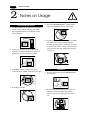
Environmental Limits
1. Use MONITOUCH at an ambient temperature of
0~50ºC, and a relative humidity of 85 %RH.
(But, a V610 STN multi-color display can be
used at 0-40ºC.)
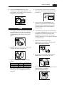
5. Never install MONITOUCH in a place where
impacts or vibrations may be transmitted.
0~50C˚
50
40
30
20
10
0
2. Install a forced fan or an air conditioner to
maintain the ambient temperature when it is
higher than the above mentioned range.
6. Avoid any place in which there is the possibility
that water, corrosive gas, flammable gas,
solvents, grinding fluids or cutting oil can come
in contact with the unit. Never install the unit in
a place where dust, salt and metallic particles
are present.
Fan
YOUZAI
Vent
3. Avoid places where moisture may easily
condense due to sudden temperature changes.
Locations
1. Secure sufficient space around MONITOUCH
for ventilation.
4. Avoid direct sunlight.
2. Never attach MONITOUCH to the top of any
apparatus generating high levels of heat
(heater, transformer, large-capacity resistor,
etc.).
1 Notes on Usage
3. Never install MONITOUCH in the same
compartment as high-voltage equipment. The
unit should be at least 200 mm away from highvoltage lines or power cables.
1-3
4. Securely fasten and lock every connector for
each cable. Double-check this before turning
the power on.
k!
Loc
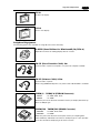
5. In a dry environment, MONITOUCH may
generate a large amount of static electricity.
Therefore, before touching the unit, touch a
grounded metallic section to discharge the
static electricity.
Usage
1. An emergency stop circuit must be composed of
an external relay circuit with a start signal for
MONITOUCH built in. Do not create switches
on MONITOUCH to be used in case of emergency.
Switch to be used
in emergency
6. A receiving error may occur on a device that is
connected to MONITOUCH such as a PLC or a
temperature controller by starting up both
equipments at the same time. In such case,
follow the instructions of such device’s manuals
to handle the error.
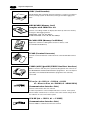
7. Application of thinner may discolor
MONITOUCH. Use alcohol or benzine available commercially for cleaning.
Emergency
Stop
2. MONITOUCH has a glass screen. Never drop
or subject the unit to strong impacts.
Alcohol
BENZINE
8. Never remove any printed circuit board from
MONITOUCH. (This will harm the unit.)
3. Tighten mounting screws with the following
torques.
Screw
Screw Size
Torque (N m(kgf cm))
V606/608
M3
0.3-0.5 (3-5)
V606i
M4
0.3-0.5 (3-5)
V610/612
M4
0.5-0.7 (5~7)
Type
Note :Never fasten these screws too tightly,
otherwise the cover of MONITOUCH may be
deformed.
9. Never operate the display by using a tool with a
sharp point like a screwdriver.
Touch the display by fingers.
a tool with a
sharp point
like a screwdriver
1 System Composition
1-4
3
System Composition
System Composition / Model Indication / Peripheral Equipment
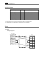
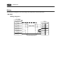
System Composition
The following illustration shows possible system configurations using V6.
Panel Editor
for V series
During operation
(Link communication)
Transferring
screen data
disc
Creating screens
run
stop
RS-232C/RS-422
V6-CP
RESET
Personal Computer (PC)
V-SFTE
V6
During operation
(Universal serial
communication)
Link Unit
RS-232C/RS-422
Transferring
screen data
or
Memory manager
/Data logging
Transferring
screen data
V6-CP
Universal-purpose
computer
Exclusive Cable
CREC-CP
Video / CCD camera
Cable
Card Recorder
V6-BCD
Printer Cable
CREC
*1
V6-PT
Bar Code Reader
Cable
V6-TMP
Printer
PV
SV
AT
OUT1
OUT2
SET
ALM1
R/S
ALM2
Temperature Controller
*1
The interface for video function (using only in V610T/S and V612T) is optional for Maker.
1 System Composition
1-5
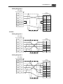
List of Models
The characters on the right of model names represent optional features and special specifications.
(None) : Analog sw type
M : Matrix sw type
1 : Standard
(None) : 100-240V AC
D : 24V DC
(None) : Analog sw type
M : Matrix sw type
* Matrix sw type is available except V610S.
C : STN color LCD
M : STN Monochrome LCD (white mode)
0 : None
1 : Video interface
2 : RGB interface (only V610T)
1 : Standard
2 : Card interface
(None) : Analog sw type
M : Matrix sw type
1 : Standard
T : TFT color LCD
C : STN color LCD
S : TFT color LCD SVGA
T : TFT color LCD
C : STN color LCD
M : STN Monochrome LCD (blue mode)
(None) : 100-240V AC
D : 24V DC
(None) : Analog sw type
M : Matrix sw type
0 : None
1 : Video interface
1 : Standard
2 : Card interface
T : TFT color LCD SVGA
C : STN color LCD SVGA (selling finished in December 2000)
1 : Standard
C : STN color LCD
All type of model have the printer port.
Models compatible with Overseas Specifications
(CE Marking and UL Mark)
(Analog sw type)
1 : Standard
C : STN color LCD
M : STN Monochrome LCD (white mode)
(Analog sw type)
(None) : Analog sw type
M : Matrix sw type
1 : Standard
T : TFT color LCD
C : STN color LCD
M : STN Monochrome LCD (blue mode)
1 : Standard
C : STN color LCD
(Matrix sw type)
(Analog sw type)
D : 24V DC
0 : None
1 : Video interface
* (only T and S type)
1 : Standard
2 : Card interface
T : TFT color LCD
C : STN color LCD
S : TFT color LCD SVGA
All type of model have the printer port.
(Matrix sw type)
(Analog sw type)
D : 24V DC
0 : None
1 : Video interface
1 : Standard
2 : Card interface
T : TFT color LCD SVGA
1 System Composition
1-6
List of Options
Type
Optional
by Manufacturer
Item
V606
C/M
V606i
T/C/M
V608C
V610C
V610T
V610S V612C
*1
Card Interface
Video Interface
Analog RGB Input
Interface
Extension I/O Unit : E-I/O
(16 inputs / 16 outputs)
Optional by User
Serial Extension I/O : V-I/O
(16 inputs / 16 outputs)
FPROM Cassette
(4Mbyte)
V6EM/4
V6EM/4i
V6EM/RS
SRAM Cassette
(512kbyte)
V6EM/RSi
Communication Interface Unit
: CU-00, 01, 02, 03, 04, 05 * 2
Communication Interface Unit
for V606 : CUS-00, 01 * 2
Card Recorder
: CREC
*1
Terminal Converter
: TC485
*1
*2
Prepare for V6 with card interface, or V6 and CREC(card recorder).
CU-00/CUS-00 : JPCN-1, CU-01/CUS-01: T-LINK, CU-02 : CC-LINK,
CU-03 : Ethernet or FL-net, CU-04 : PROFIBUS, CU-05 : MELSEC-NET10
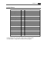
Model Indication
V606
A 5.7 inch display.
V606i
A 5.7 inch display.
V608
A 7.7 inch display.
V612T
1 System Composition
1-7
V610
A 10.4 inch display.
V612
A 12.1 inch display.
Peripheral Equipment
The following options are available for using V6 series more effectively.
V-SFTE (Panel Editor for Windows95/98/NT4.0)
Application software for editing display data for V series.
V6-CP (Data Transfer Cable) 3m
Connects V6 to a personal computer, or a personal computer to CREC.
V6-PT (Printer Cable) 2.5m
Connects V6 to a printer.
When using CBM292/293 printer, our printer cable “V6-PTCBM” is available.
· V6EM/4
: for V608, V610, V612
· V6EM/4i
: for V606i
Extension print circuit board to extend the memory for display data back-up.
There is 4Mbyte type.
1
P
R
O
M
E
1
-M
P
J
7
F
C
1
N
C
V
9
M
0
2
0
0
4
F
R
O
M
0
V6EM/4 · V6EM/4i (FPROM Cassette)
M n O 2-
JAP
AN
SANYO
Li
CR2430
TS
N
C
-2
C
B
0
2
1
V 7
6 2
-M
P
1
V6EM/RS · V6EM/RSi (SRAM Cassette)
CELL
3 VO
L
· V6EM/RS
: for V608, V610, V612
· V6EM/RSi
: for V606i
Extension print circuit board to back-up the memory for sampling data,
Internal Memory and Memo Pad. There is 512kbyte type. It is also possible
to set the calendar for displaying in V6 at this cassette.
1 System Composition
1-8
CREC (Card Recorder)
Reads display data created by personal computer, or works as an external
memory storage system for the memory manager and data logging functions.
REC-MCARD (Memory Card)
complies with JEIDA Ver.4.0
H
C
U
O
IT
N
O
M
F
56
C2
RE
Used as a recording medium for display data back-up and for the memory
manager or data logging function.
SRAM 256K, 512K, 1M, 2M, 4Mbyte
FLASH ROM 256K, 512K, 1M, 2M, 4M, 16Mbyte
M-CARD SFTE (Memory Card Editor)
M-CARD
SFT
Application software for editing data stored in a memory card.
(For Windows95/98/NT 4.0)
SERIAL
No.
MONI
TOUC
H
TC485 (Terminal Converter)
CN
1
SW
TB
Used for connection between a V6 and a PLC at the RS-422/485 terminal
block.
1
1
V-MDD (ACPU/QnACPU/FXCPU Dual Port Interface)
G
P
P
V-MD
D
123
GD
Add-on connector with two ports, specifically designed for the connector on
the MITSUBISHI's ACPU/QnACPU/FXCPU programmer. This can improve
operability of the ACPU/QnACPU/FXCPU programmer that is directly
connected.
CU-xx [xx : 00 -> JPCN1, 01 -> T-LINK, 02 -> CC-LINK,
03 -> Ethernet or FL-net, 04 -> PROFIBUS, 05 -> MELSEC-NET10]
(Communication Interface Unit)
Used to communicate with each network.
It makes it possible to connect multiple V6 series to a PLC. This system,
which enables other devices to connect to the same network, brings about
the reduction in costs of the whole system.
CUS-XX [00 -> JPCN1, 01 -> T-LINK]
(Communication Interface Unit)
Used for V606 to communicate with each network.
1 System Composition
1-9
E-I/O (Extension I/O Unit)
Used as an external I/O unit for PLC. It has 16 inputs and 16 outputs.
(It cannot be used for V606, V606i and V608.)
V-I/O (Serial Extension I/O)
Used as an external I/O unit for PLC. It has 16 inputs and 16 outputs.
DC24V
IN1
FG
IN0
IN2
IN3
IN4
IN5
IN6
IN7
IN8
MJ1
IN9
IN10
IN11
IN12
IN13
IN14
IN15
OUT1
COM+
OUT0
OUT2
OUT3
OUT4
OUT5
OUT6
OUT7
COM1
OUT8
OUT9
OUT10
OUT11
OUT12
OUT13
OUT14
COM2
OUT15
V6-BCD (Cable for Bar Code Reader) 3m
Connects V6 to a bar code reader.
V6-MLT (Cable for Multi-Link 2 master station) 3m
A cable which is used for connecting the V6 master station and the V6 slave
station in the Multi-Link 2 connection.
V6-TMP (Cable for Temperature Controller) 3m
Connects V6 to a temperature controller.
V6XX-GS [XX:
06 -> V606/V606i, 08 -> V608,
10 -> V610, 12 -> V612]
(Protection Sheet)
Protects the operation panel surface. Five sheets are included in one
package.
V6XXX-FL [XXX : 06C -> V606C, 06M -> V606M,
08C -> V608C, 10C -> V610C, 10T -> V610T,
10S -> V610S, 12C -> V612C, 12T -> V612T]
(Backlight for Replacement)
Placement backlight parts for V6 series.
1 - 10
4
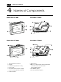
1 Names of Components
Names of Components
Front Side of V606
Rear Side of V606
CN2
Front Side of V606i
MJ2
MJ1
(+)
(-)
CN1
DC24V
Rear Side of V606i
24VDC
MJ2
CN2
1.
2.
3.
4.
5.
7.
8.
Mounting holes for fixtures
Display
Function keys (Refer to P1-49.)
Power lamp
DC input terminal of power supply
CN1: for PLC (RS-232C, RS-422)
CN2: for printer
MJ1
CN1
9. Dip switches
10. MJ1, 2: for data transfer and for temperature
controller and for bar-code reader
and for CREC (option)
11. for V6EM/X (option)
13. for CU-XX/CUS-XX (option)
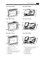
1 Names of Components
Front Side of V608
1 - 11
Rear Side of V608
DC24V
(+)
(-)
MJ1
CN1
MJ2
CN2
Front Side of V610
Rear Side of V610
L
100240VAC
N
CN1
NC
MJ2
MJ1
CN2
Front Side of V612
Rear Side of V612
L
100240VAC
N
CN1
NC
MJ2
MJ1
CN2
1.
2.
3.
4.
6.
7.
8.
9.
Mounting holes for fixtures
Display
Function keys (Refer to P1-49.)
Power lamp
AC / DC input terminal of power supply
CN1: for PLC (RS-232C, RS-422)
CN2: for printer
Dip switches
10. MJ1, 2: for data transfer and for temperature
controller and for bar-code reader
and for CREC (option)
11. for V6EM/X (option)
12. for video (option)
13. for CU-XX (option)
14. for E-I/O (option)
15. Card interface (option)
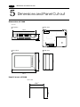
1 - 12
5
1 Dimensions and Panel Cut-out
Dimensions and Panel Cut-out
Dimensions of V606
Unit : mm
Rear View
Top View
5
45
173.6
CN1
CN2
MJ2
Side View
130.8
138.8
Front View
MJ1
182.5
Panel Cut-out of V606
Unit : mm
+0.5
-0
131 +0.5
-0
174
1 Dimensions and Panel Cut-out
1 - 13
Dimensions of V606i
Unit : mm
Front View
Side View
SYSTEM
F1
F3
POWER
138.8
130.8
F2
F4
F5
182.5
Bottom View
6
Rear View
4
47.3
24VDC
Do not remove this seal.
unless the optional unit is mounted.
MJ2
MJ1
CN1
CN2
Panel Cut-out of V606i
Unit : mm
+0.5
-0
131 +0.5
-0
174
1 - 14
1 Dimensions and Panel Cut-out
Dimensions of V608
Unit : mm
Top View
Rear View
220
(+)
DC 24V
60.1
( )
CN1
6
MJ2
CN2
Front View
165
175
Side View
230
Panel Cut-out of V608
Unit : mm
+0.5
-0
+0.5
-0
165.5
220.5
MJ1
1 Dimensions and Panel Cut-out
1 - 15
Dimensions of V610
Unit : mm
Rear View
Top View
288
L
100240VAC
N
CN1
16
76.3
NC
MJ2
CN2
Front View
215.2
240
Side View
310
Panel Cut-out of V610
Unit : mm
+0.5
-0
+0.5
-0
216.2
289
MJ1
1 - 16
1 Dimensions and Panel Cut-out
Dimensions of V612
Unit : mm
Top View
Rear View
312
L
100240VAC
NC
CN1
16
79.8
N
MJ2
CN2
Side View
245.2
270
Front View
334
Panel Cut-out of V612
Unit : mm
+0.5
-0
+0.5
-0
246.2
313
MJ1
1 Mounting Procedure
6
1 - 17
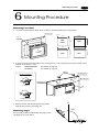
Mounting Procedure
Mounting Procedure
1. Cut out the mounting panel (Max. thick: 3.2 mm) to match the dimensions shown below.
Mounting panel
Unit : mm
174
220.5
+0.5
-0
+0.5
-0
Cut-out
289
165.5
+0.5
-0
V606
V606i
+0.5
-0
+0.5
-0
V608
131
220.5
+0.5
-0
313
165.5 -+0.5
0
V610
246.2
216.2
+0.5
-0
+0.5
-0
+0.5
-0
V612
2. Insert the fixtures attached to V6 into the mounting holes on V6. Tighten them with the locking screws.
Number of the fixtures : 4 pcs
torque
:V606/V606i/V608
0.3~0.5N·m (3~5kgf·cm)
:V610/V612
0.5~0.7N·m (5~7kgf·cm)
Fixture
Mounting panel
Dimensions of Fixtures
(Unit : mm)
Mounting hole
10.5
20
.0
Mounting hole
17.8
for V606/V608
V6
(+)
DC 24V
(-)
MJ2
MJ1
10.5
30
.0
17.8
for V606i/V610/V612
90˚
3. Mount unit flash with mounting plate with gasket
tight against outside of mounting unit.
135˚
pl
ay
135˚
The unit (V6) shall be installed within the angle of 0 to
135 degrees as shown below.
D
is
Mounting Angle
Display
0˚
1 Wiring
1 - 18
7
Wiring
Electrical Wiring
Connects the cable for power supply to TB1 on the rear side of V6.
DC24V
(+)
(-)
MJ1
Power supply
DC24V 10%
(+)
DC 24V
(-)
CN1
MJ2
CN2
Earth
V606/V606i/V608
Type : AC100-240V
L
Type : DC24V
+
L
Power supply
DC24V 10%
24VDC
CN1
Power supply
100-240VAC
100240VAC
N
NC
-
N
MJ2
NC
NC
MJ1
CN2
Earth
Earth
V610/V612
When TB1 is used for wiring, refer to the following table.
Type
Screw Screw Size
Torque (N m)
Clamp Terminal (Unit : mm)
V606/V606i/V608
M3.5
0.5 (5kgf cm)
7.1MAX
7.1MAX
V610/V612
M3
0.5 (5kgf cm)
7.9MAX
7.9MAX
The power source used must be within the allowable voltage fluctuation.
Use a power source with low noise between the cables or ground and the cable.
Use as thick a power cable as possible to minimize any drop in voltage.
Keep cables of 100V AC and 24V DC sufficiently away from high-voltage, large-current cables.
Notes on Usage of V610/612 100-240V AC Specifications
Generally, an isolating transformer improves noise resistance. However, if the display unit is far away
from the secondary port of the transformer and noise gets mixed in, an isolating transformer becomes
unnecessary.
If any power voltage fluctuation caused by noise is expected, it is recommended that a voltage
stabilizer (effective in noise resistance) be used.
Power Supply
Insulation transformer
or
Stabilized transformer
to V610/612
1.25mm
2
twisted
1 Wiring
1 - 19
Grounding
This equipment must be earthed.
V6
other
equipment
An independent earth pole shall be used for MONITOUCH.
(The level of grounding resistance should be less than 100 Ω.)
Use a cable which has a nominal cross section of more than
2mm2 for grounding.
Grounding point shall be near the MONITOUCH to shorten the
Grounding resistance : less than 100Ω
distance of grounding wires.
When the unit is grounded along with other machines, or is
grounded to a part of a building, it can be adversely affected.
If any input-output errors occur due to the grounding, detach
the FG terminal from the ground.
Wiring for Communication
Never place the communication cable
Wiring duct
with electric circuits.
Never bundle these cables together with
other wires in ducts or electric boxes
using cord locks. Although it is tempting
to bundle all the cables neatly together,
this does not necessarily lead to a noiseresistant configuration.
It is recommended that the communication cable be independently wired.
Communication cable
Communication cable
Power cable and control cable
Power cable and control cable
Cord lock
1 - 20
1 Specifications
8
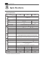
Specifications
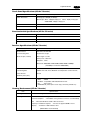
General Specifications
Type
V606i
V606
Item
Rated Voltage
24V DC
Power Supply
Permissible Range
24V 10% DC
of Voltage
10ms or less
Permissible Momentary Power Failure
Demand
Physical Environment
10W or less
20W or less
15A
1ms
15A
1.5ms
Rushed Electric Current
DC external terminals to FG : 500V AC per min.
With-stand voltage
Insulation Resistance
500V DC, 10M or more
Ambient Temperature
0 ~+50 (V610 STN Color : 0 ~+40 )
-10
Storage Ambient Temperature
~+60
85% RH or less (without dew condensation)
Ambient Humidity
No conductive dust
Dust
No cutting oil or no organic solvent to cling to the unit
Solvent Resistance
No corrosive gas
Corrosive Gas
Vibration Resistance
Mechanical
Working
Conditions
V608
Vibration frequency: 10~150Hz, Acceleration: 9.8m/s 2 (1.0G)
Single amplitude: 0.075mm, 3 directions of X, Y and Z: one hour
Pulse shape: Sine half wave,
Shock Resistance
Electrical
Working
Conditions
Peak acceleration: 147m/s2 (15G), 3 directions of X, Y and Z: six times
Noise voltage: 1500Vp-p, noise width: 1 s
Noise Resistance
Contact: 6kV , Air: 8kV
Static Electricity Discharge Resistance
Grounding resistance: less than 100
Mounting Conditions
Grounding
Structure
Protection structure: front panel complies with IP65 (when using gasket)
rear panel complies with IP20
Form: in a body
Mounting procedure: inserted in a mounting panel
Cooling naturally
Cooling System
Weight
Dimensions W X H X D (mm)
Panel Cut-out (mm)
Case Color
Material
Approx. 0.8kg
182.5 X 138.8 X 50
174
+0.5
-0
X 131
+0.5
-0
Approx. 1.1kg
Approx. 0.8kg
*1
182.5 X138.8 X 57.3
230 X 175 X 66.1
+0.5
-0
220.5-0 X 165.5 -0
174
X 131
+0.5
-0
+0.5
GREY
BLACK*2
GREY
PC/ABS
PC/PS
PC/ABS
*1 including 4mm, the size of boss for communication unit
*2 equivalent to the Munsell color system N-2.0
+0.5
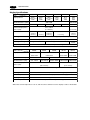
1 - 21
V610
AC
Power
Supply
V612
DC
100/240V AC
85-265V AC
Power
Supply
AC
24V DC
24V
Power
Supply
DC
24V DC
100/240V AC
10% DC
85-265V AC
(47-440Hz)
Power
Supply
24V
10% DC
(47-440Hz)
20ms or less
10ms or less
20ms or less
10ms or less
25W or less
45VA or less
25W or less
50VA or less
20A : 100V AC
30A
20A : 100V AC
30A
30A : 200V AC
6ms
30A : 200V AC
6ms
AC external terminals to FG DC external terminals to FG AC external terminals to FG DC external terminals to FG
: 1500V AC per min.
: 1500V AC per min.
: 500V AC per min.
: 500V AC per min.
500V DC, 10M or more
0 ~+50 (V610 STN Color : 0
-10
~+40 )
~+60
85% RH or less (without dew condensation)
No conductive dust
No cutting oil or no organic solvent to cling to the unit
No corrosive gas
Vibration frequency: 10~150Hz, Acceleration: 9.8m/s 2 (1.0G)
Single amplitude: 0.075mm, 3 directions of X, Y and Z: one hour
Pulse shape: Sine half wave,
Peak acceleration: 147m/s2 (15G), 3 directions of X, Y and Z: six times
Noise voltage: 1500Vp-p, noise width: 1 s
Contact: 6kV , Air: 8kV
Grounding resistance: less than 100
Protection structure: front panel complies with IP65 (when gasket using)
rear panel complies with IP20
Form: in a body
Mounting procedure: inserted in a mounting panel
Cooling naturally
Approx. 2.5kg
Approx. 3.0kg
310 X 240 X 92.3
334 X 270 X 95.8
+0.5
289 +0.5
-0 X 216.2 -0
+0.5
313+0.5
-0 X 246.2 -0
GREY
PC/ABS
1 - 22
1 Specifications
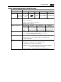
Display Specifications
Item
Type
Display Device
V606C
V606M
V606iT
STN
STN
STN
TFT
STN
Color
Monochrome
Color
Color
LCD
LCD
LCD
Color
LCD
LCD
LCD
0.36 X 0.36
0.12 X 0.36
0.36 X 0.36
320 X 240
640 X 480
0.12 X 0.36
0.36 X 0.36 0.082X0.246
157.4 X 118.1
115.2 X 86.4
W X H (mm)
(7.7 inches)
(5.7 inches)
Monochrome
8 gradation
+ blinking
Color
V608C
STN
Effective Display Area
16 colors
+ blinking
Monochrome
8 gradation
+ blinking
128 colors
+ blinking
16 colors
16 colors
+ blinking
Cold cathode rectifier (which can be exchanged by a user except for V606i )
Back-light
By function switches (only in case of STN type)
Contrast Adjustment
Back-light Average Life*
Approx.
40,000h
Approx. 50,000h
Approx. 40,000h
The lamp is lit when the power is supplied.
Power Lamp
Item
V606iC
Monochrome
Resolution W X H (dots)
Dot Pitch W X H (mm)
V606iM
Type
Display Device
Resolution W X H (dots)
Dot Pitch W X H (mm)
V610C
V610T
V610S
V612C
V612T
STN
TFT
STN
TFT
Color LCD
Color LCD
Color LCD
Color LCD
800 X 600
640 X 480
0.11 X 0.33
0.33 X 0.33
0.264 X 0.264
0.1025 X 0.3075 0.3075 X 0.3075
Effective Display Area
211.2 X 158.4
246.0 X 184.5
W X H (mm)
(10.4 inches)
(12.1 inches)
Color
Back-light
Contrast Adjustment
Back-light Average Life*
Power Lamp
128 colors + blinking 16 colors
Cold cathode rectifier (which can be exchanged by a user)
By function switches (only in case of STN type)
Approx. 25,000h
The lamp is lit when the power is supplied.
* When the normal temperature is 25°C, and the surface luminance of the display is 50% of the default.
1 Specifications
1 - 23
Display Function Specifications (All the V6 series)
Item
Specifications
Display Language
Japanese
Eng./W. Europe
Chinese
Chinese (simplified)
Korean
Characters
ANK code
Latin 1
ASCII code
ASCII code
ASCII code
1/4-size, 1-byte
2-byte (16-dot) JIS 1st and 2nd
2-byte (32-dot)
Size of Characters
Chinese
Chinese (simplified) Hangul (without Kanji)
JIS 1st
1/4-size : 8 X 8 dots
1-byte : 8 X 16 dots
2-byte : 16 X 16 dots or 32 X 32 dots
Enlarge : W, 1-8 H, 1-8
Number of Characters
Resolution
320 X 240
640 X 480
800 X 600
1/4-size
40 columns X 30 lines
80 columns X 60 lines 100 columns X 75 lines
1-byte
40 columns X 15 lines
80 columns X 30 lines 100 columns X 37 lines
2-byte
20 columns X 15 lines
40 columns X 30 lines 50 columns X 37 lines
Property of Characters
Display property : normal, reverse, blinking, bold, shadow
Color : 128 colors + blinking 16 colors / 16 colors + blinking
/ Monochrome 8 gradation + blinking
Kind of Drawing
Lines : line, continuous lines, box, parallelogram, polygon
Circles : circle, arc, sector, ellipse, elliptical arc, elliptical sector
Others : tile patterns
Property of Drawing
Type of lines : 6 types (fine, thick, dot, chain, broken, two-dot chain)
Tile patterns : 16 types (incl. user-definable 8 types)
Display property : normal, reverse, blinking
Display color : 128 colors + blinking 16 colors / 16 colors + blinking
/ Monochrome 8 gradation + blinking
Color specification : foreground, background, boundaries (line)
1 Specifications
1 - 24
Function Performance Specifications (All the v6 series)
Specifications
Item
Screens
Max. 1024
Screen Memory
FP-ROM (flash ROM), Appox. 2,816kbytes*1 (different from the language)
Switches
768 per screen (192 per screen for V606/V606i)
Actions of Switch
Set, reset, momentary, alternate, to light
(possible to press a function switch and a display switch at the same time)
(Matrix type : 2 switches on the display can be pressed at the same time)
Lamps
Reverse, blinking, exchange of graphics
768 per screen (192 per screen for V606/V606i)
Data Setting
Graphs
Pie, bar, panel meter and closed area graph can be displayed without limit.
Total capacity per screen: within 128kB *2
Statics and trend graphs: Max. 256 per layer *3
Numerical Data Display
No limits, total capacity per screen: within 128 kB
*2
Character Display
No limits, total capacity per screen: within 128 kB
*2
Message Display
Resolution : 320X240, Max. 40 characters
640X480, Max. 80 characters
800X600, Max. 100 characters
No limits, total capacity per screen: within 128 kB
Messages
6144 lines
Sampling
Sampling display of buffer data
*2
(constant sample, bit synchronize, bit sample, relay sample, alarm function)
Multi-Overlaps
Max. 1024
Data Blocks
Max. 1024
Graphic Libraries
Max. 2560
Patterns
Max. 1024
Macro Blocks
Max. 1024
Page Blocks
Max. 1024
Direct Blocks
Max. 1024
Screen Blocks
Max. 1024
Temperature Control Network Table Max. 32
Calendar
provided
Hard-Copy
provided
Buzzer
provided, 2 types (intermittent short and long sounds)
Back-light Auto OFF Function ON at all time, specified freely
Self-diagnostic Function
Self-test function of switches
Check function of communication parameter setting
Check function of communication
*1 If the hardware version is the following version, or V606/V606i is used, the screen memory is
approx. 760kbytes.
Analog type: V612T A~E, V612C A~D, V610S A~E, V610T A~F, V610C A~E, V608C A~C
Matrix type : V612T only D, V612C only C, V610C only D
*2 The number of the setting memory is limited to 256 per screen for V606/V606i, and 1024 per screen for
other models.
*3 Layer : 4 per screen (base + 3 overlaps) In case of V606/V606i, it is limited to 256 per screen.
1 Specifications
1 - 25
Touch Panel Specifications (All the V6 series)
Item
Specifications
Switch Resolution
Analog type, 1024(W) X 1024(H)
Matrix type, V612 : 50(W) X 30(H) pcs
V610 : 40(W) X 24(H) pcs
V606/V606i : 20(W) X 12(H) pcs
Form
Resistance film form
Life of Touch Panel
Use of one million times or more
Function Switch Specifications (All the V6 series)
Item
Specifications
Number of Switches
8 (6 for V606/V606i)
Type of Switch
Pressure sensitive switches
Life of Switch
Use of one million times or more
Interface Specifications (All the V6 series)
Item
Specifications
Serial Interface
RS-232C, RS-422/485
for connecting PLC
Asynchronous type
(D-sub 25 pins, female)
Data length: 7, 8 bits
Parity: even, odd, none
Stop bit: 1, 2 bits
Baud rate: 4800, 9600, 19200, 38400, 57600, 76800, 115000bps
(115200bps is invalid for V606/V606i.)
Serial Interface 1 and 2 for
RS-232C, RS-422/485 (2-wire connection)
transferring data
CREC, Bar code, V-I/O, Multi-link 2, Temperature control network,
/other external
V-Link
(modular jack, 8 pins)
Printer Interface
Complies with centronics, half pitch 36 pins (for PC98x1)
NEC
: PR201
EPSON : compatibles with ESC/P24-84 or later
HP
: PCL Level 3
CBM292/293 printer (The screen copy cannot be printed out.)
Drawing Environment (All the V6 series)
Item
Specifications
Drawing Method
Exclusive drawing software
Drawing Tool
Name of exclusive drawing software
Personal computer
OS
: V-SFTE
: with i486 or more (pentium or more is recommended)
: Microsoft Windows 95/98 or NT version 4.0
Capacity of hard disk required
Display
: free area of approx. 60MB or more
: resolution of 640 X 480 or more
(800 X 600 is recommended)
1 Serial Connector (CN1)
1 - 26
9
Serial Connector (CN1)
CN1 is used for communicating between a PLC and a V6 (RS-232C, RS-422/485).
Serial Connector (CN1)
The pin arrangement of serial connector is as follows:
L
100240VAC
N
NC
)
CN1
CN1(Dsub 25pin
MJ2
1
MJ1
CN2
Signal
1
FG
Frame ground
2
SD
RS-232C send data
3
RD
RS-232C receive data
4
RS
RS-232C RS request to send
5
CS
RS-232C CS clear to send
Not used
6
14
7
SG
8
13
Contents
Pin No.
25
Signal ground
Not used
9
+5V
Use prohibited
10
0V
Use prohibited
11
Not used
RS-422 send data (+)
12
+SD
13
-SD
RS-422 send data (-)
14
+RS
RS-422 RS send data (+)
15
Not used
16
Not used
-RS
RS-422 RS send data (-)
18
-CS
RS-422 CS receive data (-)
19
+CS
RS-422 CS receive data (+)
17
20
Not used
21
Not used
22
Not used
23
Not used
24
+RD
RS-422 receive data (+)
25
-RD
RS-422 receive data (-)
Communication Cable of RS-232C/RS-422
RS-232C
In case of RS-232C, SD and SG, and RD and SG form a pair.
Connect the shielded cable to pin No. 1 or the connector case cover.
V6 (CN1)
Shielded cable
To the RS-232C port
of the PLC link unit
Signal
Pin No.
FG
1
Receive data
SD
2
SG
RD
3
SG
RS
4
Send data
CS
5
SG
7
1 Serial Connector (CN1)
1 - 27
RS-422
In case of RS-422, +SD and -SD, and +RD and -RD form a pair.
Use SG if possible.
Connect the shielded cable to pin No. 1 or the connector case cover.
Use TC485 which is the optional equipment made by Hakko Electronics Co., Ltd. in case of using
terminal blocks in RS-422/485 connection.
Specify terminal resistance by the dip switches on V6. (Refer to the next page.)
V6 (CN1)
Signal
Pin No.
To the RS-422 port
of the PLC link unit
Shielded cable
FG
1
+RD
24
Send data (-)
-RD
25
Send data (+)
+SD
12
Receive data (-)
-SD
13
Receive data (+)
SG
7
SG
Terminal Blocks of RS-422/485
L
100240VAC
N
NC
CN1
Connect TC485 (Terminal Converter) which is
the optional equipment made by Hakko Electronics Co., Ltd. to V6 via the serial connector on V6
(CN1) in case of using terminal blocks in RS422/485 connection.
MJ2
MJ1
CN2
CN
1
The RS-422 signal wiring of TC485 is connected
to the serial connector (CN1).
SW
TB
TC485
1
1
CN1
SW1 (set to top:
4-wire connection)
Signal
Pin No.
FG
1
SG
7
+SD
12
-SD
13
+RD
24
-RD
25
TB1
RD+
RDSD+
SDSG
FG
Specify 4-wire connection or 2-wire connection by the dip switch on TC485 (SW1).
(set to top: 4-wire connection)
TC485 (Terminal Converter)
1 - 28
1 Setting of Dip Switches
10
Setting of Dip Switches
Setting of Dip Switches (DIPSW)
ON
1
Memory Extension 2
(invalid for V606)
2
3
4
5
6
7
8
In case that the hardware version is the lower-case letter of the alphabet
: Terminal resistance of MJ2 (modular jack 2)
In case that the hardware version is the capital letter of the alphabet
: Not used
Not used
RD terminal resistance of pin No. 24 and 25
Terminal resistance of MJ1(modular jack 1)
Keep DIPSW 2, 3, 4and 5 (not used) OFF.
Setting of Memory Extension 2 (This dip switch is invalid for V606. Keep DIPSW 1 OFF.)
• Set DIPSW 1 ON in case of selecting “Memory Extension 2.”
(Refer to “Operation Instruction for V6EM/4·V6EM/4i (FPROM cassette).”)
Setting of Terminal Resistance depends on the hardware version of the unit.
Hardware version is mentioned in the "LOT No:" column on the back of the unit.
hardware version
TYPE
LOT No
INPUT
CURRENT
:V610T10
:9040054 E
:100-240VAC
:0.6-0.4A
MADE IN JAPAN
◊ In case that the hardware version is the lower-case letter of the alphabet.
• Set DIPSW 7 ON in case of connecting with CN1 by connection of RS-422/485.
• Set DIPSW 6 (DIPSW8) ON in case of connecting with Modular Jack 1/2 by the connection as
below.
Multi-link2 communication (master)
Temperature controller communication by connection of RS-485
Card Recorder : CREC (option) is used
Serial Extension I/O : V-I/O (option) is used
Terminal V6 connected with V-Link by connection of RS-485
◊ In case that the hardware version is the capital letter of the alphabet
• Set DIPSW 7 ON in case of connecting with CN1 by connection of RS-422/485.
• Set DIPSW 6 ON in case of connecting with Modular Jack 1 by the connection as below.
Multi-link2 communication (master)
Temperature controller communication by connection of RS-485
Card Recorder : CREC (option) is used
Serial Extension I/O : V-I/O (option) is used
Terminal V6 connected with V-Link by connection of RS-485
• The terminal resistance of MJ 2 is always ON.
1 Modular Jack 1 & 2
11
1 - 29
Modular Jack 1 & 2
Modular Jack 1 & 2 (MJ1/2)
The right diagram is the pin arrangement and
the signal name of modular jack 1 & 2.
MJ1/2
12345678
Setting of Modular Jack 1 & 2
(MJ1/MJ2)
Pin No. Signal
Contents
1
RS-485 + data
+SD/RD
2
RS-485 - data
-SD/RD
3
+5V
Output power supply
Max. 150mA
4
+5V
Signal ground
5
0V
6
0V
RS-232C receive data
7
RD
RS-232C send data
8
SD
Specify the use of MJ1/MJ2 by the software (V-SFTE).
Select [System Setting] from [Item], and click [Others]. The [Others] dialog is displayed. The setting
items of [Modular Jack 1] and [Modular Jack 2] in the [P2] menu are as follows.
Modular Jack 1
Modular Jack 2
[Editor port]
[Not used]
[Memory Card]
[Memory Card]
[Barcode]
[Barcode]
[V-I/O]
[V-I/O]
[Multi-Link]*1 *2
[Multi-Link]*1 *2
[Temp. CTRL Net]*2
[Temp. CTRL Net]*2
[V-Link]*2
[V-Link]*2
[Touch Switch]*3
[Touch Switch]*3
[Ladder Tool]
[Ladder Tool]
[Serial Printer]
[Serial Printer]
It is impossible to select both [Multi-Link] and [Temp. CTRL Net] in each setting of modular jack.
*1 It is possible to select this item when [Multi-Link 2] is selected for [Connection] and [Local Port] is
set to [1] in the [Comm. Parameter] dialog.
*2 [Multi Link 2 (master)] and [Temperature Control Network] and [V-Link] are available in the
following hardware version or later of V6. As for V606/V606i, any version can be used.
· Analog type : V612T D V612C C V610S D V610T D V610C D V608C F
· Matrix type : All version
*3 As for [Touch Switch], refer to the “Analog RGB Input” manual.
Editor Transferring
Use modular jack 1 (MJ1) in case of editor transferring.
When [Editor port] is selected for [Modular Jack 1] in the [P2] menu, it is also possible to transfer the
data while running, because the auto change of the local mode and the run mode is valid.
When [Editor port] is selected, on-line editing and the simulation mode are also available.
When the item other than [Editor port] is selected for [Modular Jack 1] in the [P2] menu, be sure to
transfer the data by the software in the local mode. On-line editing and the simulation mode are not
available.
When the data is transferred by software, use the cable for data transferring which is the optional
equipment made by Hakko Electronics Co., Ltd. (V6-CP: 3m) to connect V6 to a personal computer.
1 - 30
1 Bar Code Reader Interface
12
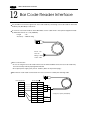
Bar Code Reader Interface
It is possible to receive the signal from a bar code reader by connecting a bar code reader to V6 via the
modular jack (MJ1/MJ2) of V6 series.
12345678
To connect a bar code reader to V6 via MJ1/MJ2, use the cable which is the optional equipment made
by Hakko Electronics Co., Ltd. (V6-BCD).
Length
: 3m
Accessory : Modular Plug
Brown : +5V
Red : 0V
Orange : RXD
Yellow : TXD
Notes on Connection
• In case of using the bar code reader which uses the CTS and RTS control, the bar code reader may
not work normally without jumping RTS and CTS.
• The output power supply (+5V) is max. 150mA. (Refer to the preview page.)
12345678
When the bar code reader connected to V4 is used, connect it to V6 by the following cable.
Barcode Reader
Signal
RTS
TXD
RXD
CTS
SG
+5V
D-sub 9pin ( )
Pin No. Signal
1
CTS
2
RXD
3
TXD
4
RTS
5
6
7
SG
8
9
+5V
*
Orange : RXD
Yellow : TXD
* Jump pins, 1(CTS) and 4(RTS).
Red : 0V
Brown : +5V
1 Printer Interface (CN2)
13
1 - 31
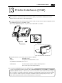
Printer Interface (CN2)
When a printer is connected to V6 via the connector (CN2), it is possible to hard-copy the screen
display of V6, the data sheet, or the sampling data.
To connect a printer to V6, use the parallel interface cable of 36 pins which is optional equipment made
by Hakko Electronics Co., Ltd. (V6-PT: 2.5m)
When using CBM292/293 printer, our printer cable “V6-PTCBM” is available.
L
100240VAC
N
CN1
NC
MJ2
MJ1
CN2
to Printer
Half pitch 36 pins
Centronics
TB1
(+)
DC 24V
(-)
to Printer
CN2
V606
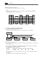
Compatible Printer Control Code System and Printer Models
NEC
PC-PR201 series
EPSON
Compatibles with ESC/P24-84 or later
HP(HEWLETT PACKARD) PCL Level 3
CBM292/293
Line thermal panel printer made by CBM Corporation.
(The screen copy cannot be printed out.)
Note of Usage of SRAM Memory Card or SRAM Cassette ;
In case of connecting a printer to V6 series with a “REC-MCARD(Memory Card:SRAM)” or “V6EM/RS ·
V6EM/RSi (SRAM cassette)” at all times, be sure to turn off a printer at the same time when turning off
V6. If a printer is not turned off when V6 is turned off, the voltage will circulate from the power supply
line of a printer to make the power consumption of SRAM cassette’s backup battery increase, and
finally, the backup battery will consume drastically within a few months.
1 - 32
1 Video Interface
14
Video Interface
When a video or a CCD camera is connected to the optional V6 which has a video interface, the image
which is taken by a video or a camera is displayed directly in a screen of V6 series (only in case of
V610T/S and V612T).
Video Interface of V6: BNC
L
100240VAC
N
NC
CN1
BNC
MJ2
MJ1
CN2
Video Display Specifications
Display Color
: 262,144 colors
Input Channel
: 4 Channels
Signal Form
: NTSC type, PAL type
Video Input
:1.0VP-P
75 ohm unbalance
Display Size
: 640 X 480, 640 X 240, 320 X 240, 160 X 120 dots (possible to change the size)
Color Adjustment : contrast (256 steps), brightness (256 steps), color gain (256 steps)
1 Connection
15
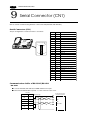
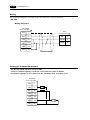
Connection
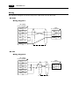
1 : 1 Link Communication
One V6 and one PLC are connected.
PLC
V6
run
stop
RS-232C or RS-422(RS-485)
1 : n Link Communication (Multi-drop)
One V6 and multiple PLCs are connected. (n = 1 to 32)
V6
RS-422/485
Maximum length 500m
(from V6 to the last PLC)
run
run
run
run
stop
stop
stop
stop
PLC1
PLC2
PLC3
PLCn
Available PLC for multi-drop communication
Manufacturer
MITSUBISHI
OMRON
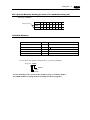
SHARP
HITACHI
MATSUSHITA
YOKOGAWA
YASKAWA
TOYOPUC
FUJI
Models
AnA/N/U series, QnA series, QnH(Q)series, A link+Net10, FX series(A prt)
SYSMAC C, CV, CQM1, CS1 DNA
JW series, JW100/70H COM Port, JW20/30 COM Port
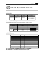
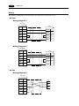
HIDIC-H
MEWNET
FA500, FA-M3, FA-M3R
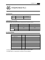
Memobus, CP9200SH/MP900
TOYOPUC
MICREX-F series, FLEX-PC series, FLEX-PC COM
Koyo
Allen-Bradley
SU/SG, SR-T
PLC-5, SLC500, Micro Logix 1000
GE Fanuc
TOSHIBA
90 series
T series
SIEMENS
SHINKO
S7-200 PPI
SELMART
SAMSUNG
KEYENCE
LG
FATEK
IDEC
MODICON
TAIAN
SPC series, N_plus, SECNET
KZ series, KV series
MASTER-K500 / K1000, MASTER-K xxxS CNET
FACON FB series
MICRO3
Modbus RTU
TP02
Universal Serial
1 - 33
1 Connection
1 - 34
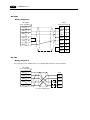
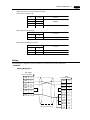
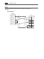
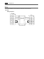
Multi-drop Communication (RS-485)
Refer to the PLC manual of each manufacturer for connection.
<E.g.>
The following example describes how one V4 is connected to three PLCs made by MITSUBISHI.
See MITSUBISHI’s manual for further details.
V6 (CN1)
Link unit
Link unit
Link unit
Signal Pin No.
Signal
Signal
Signal
FG
1
FG
FG
FG
+SD
12
RDA
RDA
RDA
-SD
13
RDB
RDB
RDB
+RD
24
SDA
SDA
SDA
-RD
25
SDB
SDB
SDB
SG
7
SG
SG
SG
SD/RD terminal resistance
(ON)
* Use twist shielded cable.
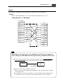
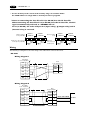
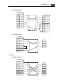
n : 1 Link Communication (Multi-link2)
Up to 4 units can be connected to one PLC.
* Between a PLC and the V6 master station is the same as those for 1:1 communication.
PLC
Communication between the stations : RS-485 (2-wire system) Maximum length: 500 m
(b)
CN1
MJ2
V6 master
(Local Port 1)
terminal
(a)
(c)
(d)
CN1
V6 slave
(Local Port 2)
(e)
CN1
V6 slave
(Local Port 3)
CN1
V6 slave
(Local Port 4)
Available PLCs for multi-link2.
As of July 2001, the PLCs supported are as follows. All the PLCs which are usable for 1:1 communication will be supported.
For the I/F driver, the Multi-Link 2 is supported by the version of 1.100 or later and as for a V6 master
station, make sure the hardware version of the unit is as follows.
As for V606/V606i, any version can be used.
· Analog type
: V612T D, V612C C, V610S D, V610T D, V61C D, V608C F
· Matrix type
: All version
* The Multi-Link 2 cannot be used with a communication interface unit such as CU-00, 01, 02, 03, 04,
05, CUS-00, 01.
* The Multi-Link 2 cannot be used with Temperature controll network.
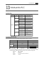
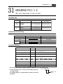
1 Connection
<Type>
MITSUBISHI : AnA/N/U series
MITSUBISHI : QnA series
MITSUBISHI : ACPU Port
MITSUBISHI : FX series
MITSUBISHI : QnACPU Port
MITSUBISHI : QnHCPU Port (A)
MITSUBISHI : QnHCPU Port (Q)
MITSUBISHI : FX series(A prt)
MITSUBISHI : FX2N series
MITSUBISHI : FX1S series
OMRON : SYSMAC C
OMRON : SYSMAC CV
OMRON : SYSMAC CS1
SHARP : JW series
SHARP : JW100/70H COM Port
SHARP : JW20 COM Port
HITACHI : HIDIC-H
HITACHI : HIDIC-S10/2 alpha
HITACHI : HIDIC-S10/ABS
MATSUSHITA : MEWNET
YOKOGAWA : FA500
YOKOGAWA : FA-M3
YOKOGAWA : FA-M3R
YASKAWA : Memobus
YASKAWA : CP9200SH/MP900
TOYOPUC
FUJI : MICREX-F series
FUJI : MICREX-F series V4
FUJI : FLEX-PC series
FUJI : FLEX-PC CPU
FUJI : FLEX-PC COM
FUJI : FLEX-PC(T)
FUJI : FLEX-PC CPU(T)
KOYO : SU/SG
KOYO : SR-T
KOYO : SR-T(K prt)
KOYO : SU/SG(K-Sequence)
A.B : PLC-5
A.B : SLC500
A.B : Micro Logix 1000
<Calendar>
Provided
Provided
Provided
Depends on the model
Provided
Provided
Provided
Provided
Depends on the model
Provided
Depends on the model
Provided
Provided
Provided
Provided
Provided
Provided
Not provided
Not provided
Depends on the model
Provided
Provided
Provided
Depends on the model
Not provided
Provided
Provided
Provided
Provided
Provided
Provided
Provided
Provided
Depends on the model
Provided
Not provided
Depends on the model
Not provided
Provided
Not provided
1 - 35
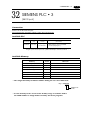
<Type>
<Calendar>
GE Fanuc : 90 series
Not provided
GE Fanuc : 90 series(SNP-X)
Not provided
TOSHIBA : T series
Provided
SIEMENS : S5
Not provided
SIEMENS : S7
Not provided
SIEMENS : S5 V4
Not provided
SIEMENS : TI500/505
Provided
SIEMENS : TI500/505(V4)
Provided
SIEMENS : S5 PG port
Not provided
SIEMENS : S7-300MPI(HMI ADP)
Not provided
SIEMENS : S7-300MPI(PC ADP)
Not provided
SAMSUNG : SPC series
Not provided
SAMSUNG : N_plus
Provided
SAMSUNG : SECNET
Depends on the model
KEYENCE : KZ series
Not provided
KEYENCE : KZ-A500 CPU Port
Provided
KEYENCE : KV series
Not provided
KEYENCE : KZ24/300 series CPU
Not provided
KEYENCE : KV10/24 series CPU
Not provided
KEYENCE : KV700 series CPU
Provided
LG : MASTER-K10/60/200
Not provided
LG : MASTER-K500/1000
Not provided
LG : LGMKX00S
Not provided
LG : MASTER-KxxxS CNET
Not provided
LG : GLOFACNET
Not provided
FANUC : Power Mate
Not provided
FATEK AUTOMATION: FACON FB series Provided
IDEC : MICRO3
Provided
MODICON : Modbus RTU
Depends on the model
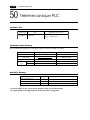
YAMATAKE : MX series
Provided
TAIAN : TP02
Provided
SAIA : PCD
Provided
MOELLER : PS4
Not provided
Telemecanique : TSX Micro
Not provided
Automationdirect : Direct LOGIC
Depends on the model
Automationdirect
: Direct LOGIC(K-Sequence) Depends on the model
Up to 4 units can be connected to one PLC.
Use the terminal converter (TC485), the optional equipment made by Hakko Electronics Co., Ltd.
See Multi-link2 manual for further details.
* Wire the shielded FG only at the one of both sides so that they are not connected.
• Set the dip switch (SW1) of TC485 as 2-wire connection when the TC485 terminal converter is used.
(b)
V6 master
MJ1/2
+
-
SG
Terminal resistor
(ON)
(c)
(d)
(e)
Terminal block
prepared by user
V6 slave
CN1+TC485
V6 slave
CN1+TC485
V6 slave
CN1+TC485
Signal
Signal
Signal
FG
FG
FG
+RD
+RD
Signal
+
+RD
-
-RD
-RD
-RD
+SD
+SD
+SD
-SD
-SD
-SD
SG
SG
SG
Terminal resistor
(OFF)
Terminal resistor
(OFF)
Terminal resistor
(ON)
SG
• Short-circuit between +RD and +SD, and -RD and -SD when the TC485 terminal converter is not
used.
1 Connection
1 - 36
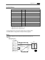
n : 1 Link Communication (Multi-link)
Multiple V6 and a PLC are connected. (n=1 to 32)
V6 1
V6 2
V6 3
V6 n
* The connections shown
below are not recommended.
RS-485
run
stop
•••
•••
•••
•••
•••
•••
•••
•••
•••
•••
•••
•••
•••
•••
•••
•••
Maximum length 500m
(from PLC to the last V6)
run
stop
PLC
Available PLCs for multi-link
Manufacturer
MITSUBISHI
MITSUBISHI
OMRON
SHARP
HITACHI
MATSUSHITA
YOKOGAWA
YASKAWA
TOYOPUC
FUJI
TOSHIBA
SIEMENS
SHINKO
SAMSUNG
LG
Models
AnA/N/U series, A link+Net10, FX series(A prt)
QnA CPU port (with V-MDD)
SYSMAC C, CV
JW series, JW100/70H COM Port, JW20/30 COM Port
HIDIC-H
MEWNET
FA500, FA-M3, FA-M3R
Memobus, CP9200SH/MP900
TOYOPUC
MICREX-F series, FLEX-PC COM
T series
S7-200 PPI
SELMART
SPC series, SECNET
MASTER-K500 / K1000
1 Connection
1 - 37
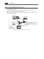
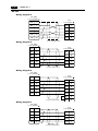
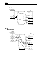
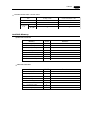
When multiple V6 are connected to a link unit of PLC, use the terminal converter (TC485), the optional
equipment made by Hakko Electronics Co., Ltd. for RS-485 connection.
• Set the dip switch (SW1) of TC485 as 2-wire connection when the TC485 terminal converter is used.
V6+TC485
V6+TC485
V6+TC485
Link unit
Signal
Signal
Signal
Signal
FG
FG
FG
FG
+SD
+SD
+SD
+RxD
-SD
-SD
-SD
-RxD
+RD
+RD
+RD
+TxD
-RD
-RD
-RD
-TxD
SG
SG
SG
SG
RD/SD terminal resistance
(OFF)
RD/SD terminal resistance
(OFF)
RD terminal resistance
(ON)
* Use twist shielded cable.
• Short-circuit between +RD and +SD, and -RD and -SD when the TC485 terminal converter is not
used.
When multiple V6 are connected directly to MITSUBISHI’s QCPU port, the optional equipment, GDMDD2 is required.
• Set the dip switch (SW1) of TC485 as 2-wire connection when the TC485 terminal converter is used.
V6+TC485
V6+TC485
V6+TC485
V-MDD
GD port
Signal
Signal
Signal
Pin No. Signal
FG
FG
FG
1
+SD
+SD
+SD
2
-SD
-SD
-SD
3
+TxD
+RD
+RD
+RD
4
+DSR
-RD
-RD
-RD
5
+DTR
SG
SG
SG
7
SG
15
-RxD
RD terminal resistance
(ON)
RD/SD terminal resistance
(OFF)
* Use twist shielded cable.
RD/SD terminal resistance
(OFF)
+RxD
16
-TxD
17
-DSR
18
-DTR
20
21
• Short-circuit between +RD and +SD, and -RD and -SD when the TC485 terminal converter is not
used.
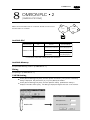
1 Operation of V6 Main Menu
1 - 38
16
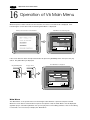
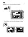
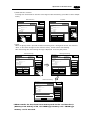
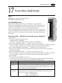
Operation of V6 Main Menu
When the power of V6 is turned on for the first time, the screen on the below left is displayed. After
transferring the screen data to V6, the following "Main Menu" is displayed.
When power is turned on for the first time:
"Main Menu" after trasferring data
V610T20
Main Menu
System Information
SYSTEM PROG. VER.1.000
Screen Data
Information
Size :
786432
1998- 9- 1
FONT
VER.1.000/1.000/1.000
JAPANESE 32
PLC Type: MITSUBISHIAnA/N/U series
Comment:
Connection: 1 : 1
Signal Level: RS232C
PLC Stat.No.: 0
Editor : MJ1
07 : 23 : 30
I/F DRV VER. 1.000
MELSEC AnA/N/U
Error: Stop
Time-Out: 0.50 sec
Retry: 3
Baud Rate: 19200
Data Length: 7
Stop Bit: 1
Parity: Even
Send Delay: 0msec
Memory-Card
I/O Test
If the screen data has been already transferred to V6, press the [SYSTEM] switch, then press the [F1]
switch. The [Main Menu] is displayed.
the [SYSTEM] switch
The "Main Menu" is displayed.
the [F1] switch
S
Y
S
T
E
M
S
Y
S
T
E
M
M
O
D
E
M
O
D
E
V610T20
Main Menu
System Information
SYSTEM PROG. VER.1.000
Screen Data
Information
Size :
786432
FONT
VER.1.000/1.000/1.000
JAPANESE 32
PLC Type: MITSUBISHIAnA/N/U series
Comment:
Connection: 1 : 1
Signal Level: RS232C
PLC Stat.No.: 0
Editor : MJ1
1998- 9- 1
07 : 23 : 30
I/F DRV VER. 1.000
MELSEC AnA/N/U
Error: Stop
Time-Out: 0.50 sec
Retry: 3
Baud Rate: 19200
Data Length: 7
Stop Bit: 1
Parity: Even
Send Delay: 0msec
Memory-Card
I/O Test
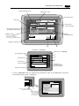
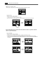
Main Menu
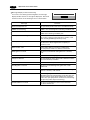
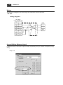
The "Main Menu" is the system menu for transferring the data between a personal computer and V6.
When the screen data is transferred from a personal computer to V6, the "Main Menu" must be displayed.
(If [Editor port] is selected for [Modular Jack 1] in the [P2] menu of the editing software or the on-line editing
is executed, it is not necessary to display the "Main Menu".
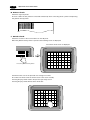
1 Operation of V6 Main Menu
System program version
1 - 39
Model name of V6
Font data version
Data size
V610T20
Main Menu
System Information
SYSTEM PROG. VER.1.000
Screen Data
Information
Size :
PLC type and comment
specified by the panel editor
786432
1998- 9- 1
FONT
VER.1.000/1.000/1.000
JAPANESE 32
Connection: 1 : 1
Signal Level: RS232C
PLC Stat.No.: 0
Own Stat.No.: 1
V6 Total: 2
Retry: 10
PLC I/F driver
version and name
Error: Stop
Time-Out: 0.50 sec
Retry: 3
PLC Type: MITSUBISHIAnA/N/U series
Comment:
Multi-Link
Multi-Link Network
Network
7 : 23 : 30
I/F DRV VER. 1.000
MELSEC AnA/N/U
Baud Rate: 19200
Data Length: 7
Stop Bit: 1
Parity: Even
Send Delay: 0msec
Setting of
comm. parameter
Multi-link setting
* This menu is displayed
only in case of selecting [1:1]
in [Connection] of [Comm. Parameter].
Editor : MJ1
Memory-Card
I/O Test
Setting of modular jack
b
a
"Main Menu" of V606/V606i
Model name of V606/V606i
System program version
a
Main Menu
1998- 7 -23
12:24:30
b
SYS PROG. VER. 1.300
I/O Test
Font data version
Memory
FONT VER.1.100/1.050/1.000
JAPANESE 32
I/F DRV VER.1.200
MELSEC AnA/N/U
-Card
c
Communication
Parameter
PLC I/F driver
version and name
PLC Type :
MITSUBISHI AnA/N/U series
Comment:
PLC type and
comment specified
by the panel editor
Editor:MJ1
Setting of modular jack
*
In case of V606/V606i, when the “Communication Parameter” switch on the “Main Menu” is pressed,
the following “Comm. Param.” is displayed.
12:24:30
Main Menu
Comm. Param.
I/O Test
Screen Data Size :
Memory
-Card
Multi-Link Network
Communication
Own Stat.No. : 1
V6 Total : 2
Retry : 10
Parameter
Connection :
Signal Level :
PLC Stat. No.:
Baud Rate :
Data Length :
Stop Bit :
Parity :
Send Delay :
Press the "Communication
Parameter" switch.
Multi-link setting
* This menu is displayed
only in case of selecting
[1 : 1] in [Connection] of
[Comm. Parameter].
Editor:MJ1
786432
Error : Stop
Time-out : 0.50 sec
Retry : 3
Multi-Link N
RS232C
00
19200
7
1
Even
20 msec
1 Operation of V6 Main Menu
1 - 40
I/O Test
When the switch 'A' on the "Main Menu" is pressed, the following "I/O Test" is displayed.
This is the test menu to check only V6 hardware.
Memory-Card
I/O Test
B
E
C
Press the [I/O Test] switch.
D
I/O Test
Main Menu
SYS
F-1
Printer Check
Switch Check
F-2
A
F-3
Self-Loop Test
Please refer to the manual, "Hardware Specifications".
F-4
Communication Port
CTS
RTS
NG
OK
Self-Loop Test
*
F-5
CN1
RS-232C
MJ1
RS-485
F-6
MJ2
F-7
In case of V606/V606i, when the switch “A” on the “Main Menu” is pressed, the following “I/O Test” is
displayed.
Then, the “Serial Test” switch on the “I/O Test” is pressed. The following “Serial Test” is displayed.
The self-loop test can be executed on this screen.
12:24:30
I/O Test
Memory
-Card
Press the "I/O Test" switch.
Communication
Parameter
E
I/O Test
Main Menu
D
A
Press the "Serial Test" switch.
Serial Test
SYS
I/O Test
Self-Loop Test
Please refer to the manual,
"Hardware Specifications".
F-1
Communication Port
Printer Check
F-2
CTS
RTS
F-3
NG
OK
F-4
Serial Test
Self-Loop
Test
Switch Check
F-5
C
B
CN1
RS232C
MJ1
RS485
MJ2
1 Operation of V6 Main Menu
1 - 41
A. Self-loop Test
This is the test menu to check the signals necessary for V6 to communicate with PLC or a personal
computer by using only V6.
Signal Test of RS-232C in CN1
Select [CN1] and [RS-232C] in [Communication Port] by pressing each switch.
Communication Port
CN1
RS-232C
MJ1
RS-485
MJ2
• Loop-back Test
Check the signals, [SD] and [RD].
1. Jump pins, 2 and 3 of CN1.
2. The test is OK, if the [OK] lamp turns on when the [Self-Loop Test] switch is pressed.
* If the [NG] lamp turns on when the same switch as above is pressed, ask the
advice of your distributor.
CTS
RTS
CTS
RTS
NG
OK
NG
OK
Self-Loop Test
Self-Loop Test
• Test of CTS/RTS
Check the signals, [CTS] and [RTS].
1. Jump pins, 4(RTS) and 5(CTS) of CN1.
2. The test is OK if the [CTS] lamp and the [RTS] lamp turn on at the same time that the [RTS]
switch is pressed. Similarly, the test is OK if the [CTS] turns off at the same time that the [RTS] is
turned off.
CTS
RTS
CTS
RTS
NG
OK
NG
OK
Self-Loop Test
Self-Loop Test
CTS
RTS
CTS
RTS
NG
OK
NG
OK
Self-Loop Test
Self-Loop Test
1 - 42
1 Operation of V6 Main Menu
Signal Test of RS-485 in CN1
Select [CN1] and [RS-485] in [Communication Port] by pressing each switch.
Communication Port
CN1
RS-232C
MJ1
RS-485
MJ2
• Loop-back Test
Check the signals, [SD] and [RD].
1. Jump each pin, 12 and 24, 13 and 25 of CN1.
2. The test is OK, if the [OK] lamp turns on when the [Self-Loop Test] switch is pressed.
CTS
RTS
CTS
RTS
NG
OK
NG
OK
Self-Loop Test
Self-Loop Test
* If the [NG] lamp turns on when the same switch as above is pressed, ask the
advice of your distributor.
• Test of CTS/RTS
Check the signals, [CTS] and [RTS].
1. Jump each pin, 14(+RTS) and 19(+CTS), 17(-RTS) and 18(-CTS) of CN1.
2. The test is OK if the [CTS] lamp and the [RTS] lamp turn on at the same time that the [RTS]
switch is pressed. Similarly, the test is OK if the [CTS] turns off at the same time that the [RTS] is
turned off.
CTS
RTS
CTS
RTS
NG
OK
NG
OK
Self-Loop Test
Self-Loop Test
CTS
RTS
CTS
RTS
NG
OK
NG
OK
Self-Loop Test
Self-Loop Test
1 Operation of V6 Main Menu
1 - 43
Signal Test of RS-232C in MJ1 and MJ2
Select [MJ1] (or [MJ2]) and [RS-232C] in [Communication Port] by pressing each switch.
Communication Port
CN1
RS-232C
MJ1
RS-485
MJ2
• Loop-back Test
Check the signals, [SD] and [RD].
Execute the test by connecting the data transfer cable (V6-CP) to CN1.
1. Set the adaptor, ADP25-9, which is attached to V6-CP, to V6-CP. And connect the modular jack
side of V6-CP to MJ1 (or MJ2), ADP25-9 side of V6-CP to CN1.
V6-CP
CN1
MJ1/2
2. The test is OK, if the [OK] lamp turns on when the [Self-Loop Test] switch is pressed.
CTS
RTS
CTS
RTS
NG
OK
NG
OK
Self-Loop Test
Self-Loop Test
* If the [NG] lamp turns on when the same switch as above is pressed, ask the
advice of your distributor.
Signal Test of RS-485 in MJ1 and MJ2
When you execute the signal test of RS-485 in MJ1 and MJ2, ask the advice of your distributor.
1 Operation of V6 Main Menu
1 - 44
B. Printer Check
Check the signal of printer.
The test is OK if the test printout is executed satisfactorily when connecting V6 to a printer and pressing
this [Printer Check] switch.
C. Switch Check
Check the reaction of the touch switches on the V6 panel.
When the [Switch Check] switch is pressed, the following screen is displayed.
The switch check screen is displayed.
Main Menu
SYS
X:
Y:
F-1
Check
Switch Check
F-2
Retu
Eras
Press the [Switch Check] switch.
Confirm that the color of the pressed area changes into white.
The white color means that the switch reacts to the touch normally.
Pressing the [F4] switch leads to the previous [I/O Test] screen.
Pressing the [F5] switch deletes all the white dots.
X:
Y:
Retu
Eras
1 Operation of V6 Main Menu
1 - 45
* In case of matrix type
When pressing the [Switch Check] switch, the following screen which is divided by a minimum size
of switch is displayed. Confirm that the color of the pressed switch changes into white. Pressing the
corner right below leads to the previous [I/O Test] screen.
the [Switch Check] screen
Main Menu
Switch Check
SYS
F-1
F-2
Press
the [Switch Check] switch.
If the pressed area is
reversed, these switches
reacts to the touch normally.
D. Test of SYSTEM & Function Switches
Check the eight switches (six switches for V606) placed vertically on the right side of the V6 panel.
The test is OK if the lamps on the screen turn on when each switch is pressed.
SYS
SYS
F-1
F-1
F-2
F-2
F-3
F-3
F-4
F-4
Press the [F4] switch.
F-5
F-5
F-6
F-6
F-7
F-7
The test is OK
when the [F-4] lamp is lit.
E. Main Menu
Pressing this [Main Menu] switch leads to the previous [Main Menu].
The "Main Menu" is displayed.
Main Menu
SYS
V610T20
Main Menu
System Information
F-1
Check
Switch Check
F-2
SYSTEM PROG. VER.1.000
Screen Data
Information
Size :
786432
PLC Type: MITSUBISHIAnA/N/U series
Comment:
Multi-Link
Multi-Link Network
Network
Press the [Main Menu] switch.
Own Stat.No.: 1
V6 Total: 2
Retry: 10
Editor : MJ1
FONT
VER.1.000/1.000/1.000
JAPANESE 32
Connection: 1 : 1
Signal Level: RS232C
PLC Stat.No.: 0
1998- 9- 1
7 : 23 : 30
I/F DRV VER. 1.000
MELSEC AnA/N/U
Error: Stop
Time-Out: 0.50 sec
Retry: 3
Baud Rate: 19200
Data Length: 7
Stop Bit: 1
Parity: Even
Send Delay: 0msec
Memory-Card
I/O Test
1 - 46
1 Operation of V6 Main Menu
Memory-Card
When the [Memory-Card] switch on the "Main Menu" is pressed, the following "Memory-Card" is displayed.
This screen is to transfer the screen data between V6 and a memory-card.
Memory-Card
I/O Test
The "Memory-Card" screen is displayed.
Press the [Memory-Card] switch.
Memory-Card
Main Menu
Port Selection
Modular Jack
MJ1
Memory-Card
Socket
Transfer
Display <--- Card
"Memory-Card" of V606/V606i
Display ---> Card
Port Selection
Transfer
Modular Jack
MJ1
Display <-- Card
Data Selection
Display --> Card
Screen Data
I/F Driver
Font Data
V6 Program
Data Selection
Main Menu
Memory-Card
Display <--> Card
Screen Data
Font Data
Start
I/F Driver
Sys. Program
Cancel
Display <-> Card
Start
Cancel
Procedure of Data Transferring
1) Port Selection
Select the [Modular Jack MJ1] switch (or [Modular Jack MJ2]) in case of using a modular jack.
Select the [Memory-Card Socket] switch in case of using a memory-card interface. When each switch
is pressed, the “Memory-Card Information” window is displayed.
In case of V606/V606i, pressing the “Close” switch leads to the original screen after checking the
memory card information.
Memory-Card
Memory-Card
Port Selection
Modular Jack
MJ1
Memory-Card
Socket
Main Menu
Memory-Card Information
Close
Port Selection
Sys. Program
:
Modular Jack
Memory-Card
Version:-.--MJ1
Socket
Font Data
:
Version:-.---/-.---/-.--I/F Driver
:
Version:-.--Screen PLC Type:
Screen Comment:
Data Selection
Transfer
Display <--- Card
Display ---> Card
Display <--> Card
Screen Data
Font Data
Start
I/F Driver
Sys. Program
Cancel
In case of selecting [Memory Card] from [Modular Jack 2] in the [Others] dialog
of V-SFTE, it is possible to select the [Modular Jack 2] switch in the [Port
Selection] menu of the [Memory-Card] screen on V6.
1 Operation of V6 Main Menu
1 - 47
2) Data Selection, Transfer
Pressing each switch leads to selection of the target for data transferring. (Possible to select multiple
items.)
Data Selection
Transfer
Memory-Card
Memory-Card
Main Menu
Close
Memory-Card Information
Main Menu
Close
Memory-Card Information
Port Selection
Port Selection
Sys. Program
:
Modular Jack
Memory-Card
Version:-.--MJ1
Socket
Font Data
:
Version:-.---/-.---/-.--I/F Driver
:
Version:-.--Screen PLC Type:
Screen Comment:
Sys. Program
:
Modular Jack
Memory-Card
Version:-.--MJ1
Socket
Font Data
:
Version:-.---/-.---/-.--I/F Driver
:
Version:-.--Screen PLC Type:
Screen Comment:
Transfer
Display <--- Card
Display ---> Card
Display <--> Card
Data Selection
Transfer
Display <--- Card
Display ---> Card
Display <--> Card
Data Selection
Screen Data
Font Data
Start
Screen Data
Font Data
Start
I/F Driver
Sys. Program
Cancel
I/F Driver
Sys. Program
Cancel
3) Start
When the [Start] switch is pressed, the data transferring starts. During data transfer, the character,
‘Start’, on the switch changes into the character, ‘Busy’, and the switch starts blinking.
After transferring data, the following message is displayed. Press the [OK] switch.
During transferring
Start transferring
Memory-Card
Memory-Card
Main Menu
Memory-Card Information
Close
Sys. Program
:
Modular Jack
Memory-Card
Version:-.--MJ1
Socket
Font Data
:
Version:-.---/-.---/-.--I/F Driver
:
Version:-.--Screen PLC Type:
Screen Comment:
Data Selection
Main Menu
Memory-Card Information
Close
Port Selection
Port Selection
Sys. Program
:
Modular Jack
Memory-Card
Version:-.--MJ1
Socket
Font Data
:
Version:-.---/-.---/-.--I/F Driver
:
Version:-.--Screen PLC Type:
Screen Comment:
Transfer
Display <--- Card
Display ---> Card
Display <--> Card
Data Selection
Transfer
Display <--- Card
Display ---> Card
Display <--> Card
Screen Data
Font Data
Start
Screen Data
Font Data
Busy
I/F Driver
Sys. Program
Cancel
I/F Driver
Sys. Program
Cancel
Finish transferring
Memory-Card
Main Menu
Memory-Card Information
Close
Port Selection
Sys. Program
:
Modular Jack
Memory-Card
Version:-.--MJ1
Socket
Font Data
:
Version:-.---/-.---/-.--I/F Driver
:
Version:-.--Screen PLC Type:
Screen Comment:
Data Selection
Transfer
Display <--- Card
Display ---> Card
Display <--> Card
WorkScreen
nomally
finished.
Data
Font Data
Start
I/F Driver
OK
V6 Program
Cancel
* When transfer the data from V6 to memorycard via the card interface(=
[Memory-Card Socket]) of V6, use SRAM type memory card. FROM type
memory card is not used.
1 - 48
1 Operation of V6 Main Menu
Message Display in Data Transferring
If an error occurs during transferring data, the message
display window shown on the right is displayed. The kinds
and the contents of the messages are as shown below.
Message
Work nomally finished.
OK
Contents
Work normally finished.
The specified operation has been concluded normally.
CREC not connecting
CREC is not connecting when selecting a modular jack.
CREC Communication Error
A communication error occurred between V6 and
CREC when selecting a modular jack.
Memory-Card not setting
A memory card is not inserted.
(Or in case of trying to write data into a memory card
when inserting FROM type memory card)
Memory-Card Capacity over
Cannot write the data into a memory card because
the data size in V6 is larger than the capacity of
a memory card.
Write Protect : ON
Cannot write data into a memory card because
the write protect switch in a memory card is ON.
Writing Error occurred.
The error occurred while writing data into a memory
card.
Selected data does not exist.
The data in the reading target does not exist.
V6 type is different.
The specified type of the data in V6 is different from the
type of the memory card data.
Selected data can not be read.
The data in a memory card cannot be read.
Reading Error occurred.
The error occurred during writing data into a flash
ROM of V6.
Data discrepant
There is some discrepancy in data, when comparing data
between a memory card and V6.
Screen data on V6 will be broken.
This message appears to inform the user that the data in
V6 will be broken by transferring the font data (the size
which is larger than the present data) from a memory
card to V6. (The [OK] switch continues the transferring.
The [Cancel] switch stops transferring.)
Undefined Error occurred.
The error occurred due to some cause other than
the above mentioned.
1 - 49
1 Function Switches
17
Function Switches
Type
[SYSTEM], [F1], [F2], [F3], [F4], [F5], [F6], [F7]
(V606/V606i : [SYSTEM], [F1]~[F5])
the [SYSTEM] switch
By pressing this switch, the functions of the switches [F1] ~ [F7] are defined.
The type of the [SYSTEM] switch is alternate. When this switch is pressed once, the
switch menu is displayed by the side of the function switches [F1] ~ [F5], and each
function switch corresponds to an item on the displayed switch menu.
When the [SYSTEM] switch is pressed again, the switch menu which is displayed on
the screen will disappear, and the functions of switches [F1] ~ [F7] are defined for the
purpose of the user. The data of these function switches is allocated to the memory
area of PLC.
S
Y
S
T
E
M
M
O
D
E
B
A
C
K
L
T
Function of [F1] ~ [F5] when the switch menu is displayed
[F1] : Mode
This switch changes the operation mode.
Main Menu Mode --> RUN Mode
Run Mode --> Main Menu Mode (possible to specify the changing time)
[F2] : Contrast Adjustment (dark) ------- invalid in case of the TFT color type
This switch adjusts the contrast of LCD. When the [F2] switch is pressed once, the LCD color becomes
dark. If this switch is held down for 1 second, the LCD color changes rapidly into darkness.
[F3] : Contrast Adjustment (intermediate) ------- invalid in case of the TFT color type
This switch also adjusts the contrast of LCD. When the [F3] switch is pressed once, the LCD color
becomes intermediate.
[F4] : Contrast Adjustment (light) ------- invalid in case of the TFT color type
This switch adjusts the contrast of LCD. When the [F4] switch is pressed once, the LCD color becomes
light. If this switch is held down for 1 second, the LCD color changes rapidly into lightness.
[F5] : Backlight
This switch turns the backlight of V6 on or off.
If you want to use this function, you have to set [Backlight] of the [Others] dialog in [System Setting].
The following list shows the backlight function specified in the editing software.
Backlight
ON
Auto 1
Auto 2
Manual
Manual2
Function Switch (F5)
Ignored.
The following actions are added to the regular functions of these items :
Even if the time does not reach the setting time, the backlight will turn off if the
[F5] switch is pressed (provided that bit 11(Backlight) of Read Area n+1 is OFF
level). (Refer to the Reference Manual.)
If you select [Manual], the backlight will turn on or off only when this switch is
pressed. Also, you can specify the item, [Backlight Power ON Time Control].
When you turn the power supply of V6 on ...
[ON] : the backlight is lit.
[OFF] : the backlight is off.
Connection to
Link Units
1. MITSUBISHI PLC • 1
2. MITSUBISHI PLC • 2
3. MITSUBISHI PLC • 3
4. MITSUBISHI PLC • 4
5. MITSUBISHI PLC • 5
6. MITSUBISHI PLC • 6
7. OMRON PLC • 1
8. OMRON PLC • 2
9. Sharp PLC • 1
10. Sharp PLC • 2
11. HITACHI PLC • 1
12. HITACHI PLC • 2
13. Matsushita PLC
14. YOKOGAWA PLC • 1
15. YOKOGAWA PLC • 2
16. YASKAWA PLC • 1
17. YASKAWA PLC • 2
18. TOYOPUC PLC
19. FUJI PLC • 1
20. FUJI PLC • 2
21. FUJI PLC • 3
22. FUJI PLC • 4
23. Koyo PLC
24. Allen-Bradley PLC • 1
25. Allen-Bradley PLC • 2
26. GE Fanuc PLC • 1
27. GE Fanuc PLC • 2
28. TOSHIBA PLC
29. TOSHIBA MACHINE PLC
30. SIEMENS PLC • 1
31. SIEMENS PLC • 2
32. SIEMENS PLC • 3
33. SIEMENS PLC • 4
34. SIEMENS PLC • 5
35. SIEMENS PLC • 6
36. Shinko PLC
37. SAMSUNG PLC
38. KEYENCE PLC • 1
39.KEYENCE PLC • 2
40. KEY ENCE PLC • 3
41. LG PLC
42. FANUK PLC
43. FATEK AUTOMATION PLC
44. IDEC PLC
45. MODICON PLC
46. YAMATAKE PLC
47. TAIAN PLC
48. SAIA PLC
49. MOELLER PLC
50. Telemecanique PLC
51. Automationdirect PLC
2 MITSUBISHI PLC • 1
1
MITSUBISHI PLC • 1
(A/Q series link unit)
Available PLC
Select PLC Type
AnA/N/U
series
PLC
A2A, A3A
AJ71C24-S6
AJ71C24-S8
AJ71UC24
A2U, A3U, A4U
AJ71UC24
A1, A2, A3
A1N, A2N, A3N
A3H, A3M, A73
AJ71C24
AJ71C24-S3
AJ71C24-S6
AJ71C24-S8
AJ71UC24
A0J2, A0J2H
Wiring Diagram
(refer to P2-5, 6)
RS-232C [Wiring Diagram 2]
RS-422 [Wiring Diagram 3]
A0J2C214-S1
A1SJ71UC24-R2
RS-232C [Wiring Diagram 1]
A1SJ71UC24-R4
RS-422 [Wiring Diagram 3]
A1SJ71UC24-PRF
RS-232C [Wiring Diagram 1]
A1SJ71C24-R2
RS-232C [Wiring Diagram 1]
A1SJ71C24-R4
RS-422 [Wiring Diagram 3]
A1SJ71C24-PRF
RS-232C [Wiring Diagram 1]
A2CCPUC24
CPU built-in port
RS-232C [Wiring Diagram 1]
QnH(A mode)
A1SJ71UC24-R2
A1SJ71UC24-R4
RS-232C [Wiring Diagram 1]
RS-422 [Wiring Diagram 3]
AJ71QC24N
RS-232C [Wiring Diagram 2]
RS-422 [Wiring Diagram 3]
AJ71QC24
RS-232C [Wiring Diagram 2]
RS-422 [Wiring Diagram 3]
A1SJ71QC24
RS-232C [Wiring Diagram 1]
RS-422 [Wiring Diagram 3]
AJ71QC24-R4(CH1)
RS-422 [Wiring Diagram 4]
AJ71QC24-R4(CH2)
RS-422 [Wiring Diagram 3]
QJ71C24
RS-232C [Wiring Diagram 1]
RS-422 [Wiring Diagram 3]
A2US
A1S, A1SJ, A2S
QnA
series
Link Unit
Q2A, Q3A, Q4A
Q2ASx
QnH(Q mode)
2-1
2-2
2 MITSUBISHI PLC • 1
Communication Setting
The recommended communication parameter setting of both PLC and V6 is as follows:
A series link unit
Setting of PLC
Comm. Parameter of V6
Baud Rate
19200bps
19200bps
Port
0 for both STATION X 10 and X1
0
Parity
Even
Even
Item
*1
Transmission
Control Mode
RS-232C
MODE1
Trans. Mode 1
RS-422
MODE5
Trans. Mode 1
Transmission
Code
Data Length
7 (ASCII)
7
Stop Bit
1
1
Sumcheck
Provided (fixed)
Write while running
Available (fixed)
Terminal Resistor at Sender
Provided (fixed)
Terminal Resistor at Receiver
Provided (fixed)
*1 If [Trans. Mode 4] is selected from [Trans. Mode] in [Comm. Parameter] of the panel editor,
specify [MODE4] in case of RS-232C, or select [MODE8] in case of RS-422.
Q series link unit
Item
Setting of PLC
Comm. Parameter of V6
Baud Rate
19200bps
19200bps
Port
0 for both STATION X 10 and X1
0
Parity
Even
Even
Transmission
Control Mode
RS-232C
Transmission
Code
Data Length
MODE5 (Binary Mode) (fixed)
RS-422
Stop Bit
8 (fixed)
1
Sumcheck
Provided (fixed)
Write while running
Available (fixed)
1
2-3
2 MITSUBISHI PLC • 1
Switch Setting
The following is an example to show the settings for both rotary dip switches and dip switches on PLC.
<E.g.> Signal Level: RS-232C, Baud Rate: 19200bps, Trans. Mode: Trans. Mode 1
ON
SW11
SW12
AJ71UC24
STATION No
10
A
9
STATION No
1
B C D E
8
7
6
5 4 3
A
9
F
0
1
2
SW14
B C D E
8
7
6
5 4 3
SW13
MODE
A
9
F
0
1
2
B C D E
8
7
6
5 4 3
SW15
F
0
1
2
SW16
SW17
ON
OFF
SW18
SW21
SW22
SW23
SW24
<E.g. 2> Signal Level: RS-232C, Baud Rate: 19200bps, Trans. Mode: Trans. Mode 1
ON
SW03
A1SJ71C24-R2
A1SJ71UC24-R2
SW04
SW05
SW06
STATION No
10
A
9
STATION No
1
B C D E
8
7
6
5 4 3
F
0
1
2
A
9
MODE
B C D E
8
7
6
5 4 3
F
0
1
2
A
9
SW07
ON
B C D E
8
7
6
5 4 3
F
0
1
2
SW08
OFF
SW09
SW10
SW11
SW12
<E.g. 3> Baud Rate: 19200bps
ON
SW01
AJ71QC24
A1SJ71QC24
AJ71QC24N
SW02
SW03
STATION No
10
STATION No
1
MODE
B C D E
B C D E
B C D E
A
9
8
7
6
5 4 3
F
0
1
2
A
9
8
7
6
5 4 3
F
0
1
2
SW04
A
9
8
7
6
5 4 3
F
0
1
2
SW05
SW06
OFF
ON
SW07
SW08
SW09
SW10
SW11
SW12
<E.g. 4> Signal Level: RS-422, Baud Rate: 19200bps, Trans. Mode: Trans. Mode 1
ON
SW01
A1SJ71UC24-R4
A1SJ71C24-R4
SW02
SW03
STATION No
10
STATION No
1
MODE
B C D E
B C D E
B C D E
A
9
8
7
6
5 4 3
F
0
1
2
A
9
8
7
6
5 4 3
F
0
1
2
SW04
A
9
8
7
6
5 4 3
F
0
1
2
SW05
ON
SW06
SW07
SW08
SW09
SW10
SW11
SW12
OFF
2-4
2 MITSUBISHI PLC • 1
Available Memory
Memory
TYPE
D
(data register)
W
(link register)
1
R
(file register)
2
TN
(timer/current value)
3
CN (counter/current value)
4
SPU (special unit)
5
M
(internal relay)
6
L
(latch relay)
7
B
(link relay)
8
X
(input relay)
9
Y
(output relay)
10
TS
(timer/contact)
11
TC
(timer/coil)
12
CS
(counter/contact)
13
CC (counter/coil)
Remarks
0
Unit No.
14
H
(link buffer)
15
SD
(special register)
16
only in QnA
SM (special relay)
17
only in QnA
SB
18
only in QnA
SW (special link register)
19
only in QnA
ZR
20
only in QnA
(special link relay)
*1
(file register [continuous access])
*1 The unit number is required in addition to the memory type and the address.
Convert a byte address into a word address to enter the data if the memory device of link unit
is byte address.
Set the memory to the extent of the memory range of each PLC model.
Use TYPE number to assign indirect memory for macro programs.
2 MITSUBISHI PLC • 1
2-5
Wiring
The following is a diagram to show the wiring of the cable which connects V6 to PLC.
RS-232C
Wiring Diagram 1
V6 (CN1)
D-sub 25pin(Male:
)
PLC
FG
1
SD
2
CD
1
RD
3
RD
2
RS
4
SD
3
CS
5
SG
5
SG
7
DR
6
RS
7
CS
8
D-sub 9pin(Male:
* Use twist shielded cables.
)
Wiring Diagram 2
V6 (CN1)
D-sub 25pin(Male:
)
PLC
FG
1
SD
2
SD
2
RD
3
RD
3
RS
4
RS
4
CS
5
CS
5
SG
7
DR
6
SG
7
CD
8
D-sub 25pin(Male:
* Use twist shielded cables.
)
2-6
2 MITSUBISHI PLC • 1
RS-422
Wiring Diagram 3
V6 (CN1)
D-sub 25pin(Male:
)
FG
1
PLC
SG
7
SDA
+SD
12
SDB
-SD
13
RDA
+RD
24
RDB
-RD
25
SG
* Use twist shielded cables.
Wiring Diagram 4
V6 (CN1)
D-sub 25pin(Male:
)
PLC
FG
1
SG
7
RDA
2
+SD
12
SDA
3
-SD
13
DSRA
4
+RD
24
DTRA
5
-RD
25
SG
7
RDB
15
SDB
16
DSRB
17
DTRB
18
D-sub 25pin(Male:
20
* Use twist shielded cables.
21
)
2 MITSUBISHI PLC • 2
2
MITSUBISHI PLC • 2
(A/QnA series CPU port)
Connection
Connect to the A/Q series CPU port.
The communication parameter setting of V6 is done automatically.
Available PLC
Select PLC Type
A CPU port
QnA CPU port
PLC
A2A, A3A
A2U, A3U, A4U
A2US(H)
A1N, A2N, A3N
RS-422
A3V, A73
A3H, A3M
A0J2H
A1S, A1SJ(H), A2S(H)
A2CCPUC24
Wiring Diagram
(refer to P2-9)
[MB-CPUQ]
made by Hakko Electronics
or
[Wiring Diagram 1]
Q2A, Q3A, Q4A
Q2AS(H)
When the CPU is updated, or the specifications are changed, there is some
possibility that V6 cannot be connected to the PLC.
2-7
2-8
2 MITSUBISHI PLC • 2
Available Memory
Memory
TYPE
D
(data register)
W
(link register)
1
R
(file register)
2
TN
(timer/current value)
3
CN (counter/current value)
4
SPU (special unit)
5
M
(internal relay)
6
L
(latch relay)
7
B
(link relay)
8
X
(input relay)
9
Y
(output relay)
10
TS
(timer/contact)
11
TC
(timer/coil)
12
CS
(counter/contact)
13
CC (counter/coil)
SD
(special register)
SM (special relay)
SB
(special link relay)
Remarks
0
*2
Unit No. *1
14
16
only in QnA
17
only in QnA
18
only in QnA
SW (special link register)
19
only in QnA
ZR
20
only in QnA
(file register [continuous access])
*1 The unit number is required in addition to the memory type and the address.
Convert a byte address into a word address to enter the data if the memory device of link unit
is byte address.
*2 File register(R) cannot be used in case of ROM operation of A series CPU.
Set the memory to the extent of the memory range of each PLC model.
Use TYPE number to assign indirect memory for macro programs.
2 MITSUBISHI PLC • 2
2-9
Wiring
The following is a diagram to show the wiring of the cable which connects V6 to PLC.
RS-422
Use the cable, [MB-CPUQ](2, 3, 5, 10, 15m) made by Hakko Electronics Co., Ltd.
Wiring Diagram 1 < MB-CPUQ >
V6 (CN1)
D-sub 25pin(Male:
)
PLC
FG
1
SG
7
2
+RxD
+SD
12
3
+TxD
-SD
13
4
+DSR
+RTS
14
5
+DTR
-RTS
17
7
SG
-CTS
18
15
-RxD
+CTS
19
16
-TxD
+RD
24
17
-DSR
-RD
25
18
-DTR
D-sub 25pin(Male:
)
20
21
* Use twist shielded cables.
Note
According to our noise tests, the attachment of a ferrite core improves
noise voltage by 650~900V and aids in preventing communication errors.
In case of direct connection with the CPU port of A/QnA series, be sure to attach the
ferrite core to the cable between V6 and the CPU port of A/QnA series for noise.
A/QnA Series
CPU
V6 Series
Ferrite core
A Ferrite core is sold as an optional accessory.
When you buy it, specify “GD-FC (internal diameter : 8mm, external diameter : 20mm)”
as the model name.
In consideration of such noise problems, it is recommended that the standard type link
unit be used in such a case when the cable length of more than 15m is required.
2 - 10
2 MITSUBISHI PLC • 2
Notes on using V-MDD (Dual Port Interface)
As the V-MDD is powered by a CPU, check that the electric capacity of the CPU is at 5V (power
consumption: max. 350mA).
The distance between the CPU and the V-MDD should be as short as possible (max. 1~1.5m).
For wiring, take appropriate measures to eliminate noise.
Specify the value more than 150 (=1.5 sec) in [Time-out Time] of [Comm. Parameter] in case of
connecting V6 to a V-MDD.
MITSUBISHI A/QnA Series
CPU
A6GPP, A7PHP, personal computer, etc.
V-M
G
P
P
123
DD
GD
In case of direct connection with the CPU port of A/QnA series,
plug the rear connector of V-MDD in the CPU port, or use the
cable "MDD-CPU" made by Hakko Electronics.
Cable ’MB-CPUQ’
Slide switch
1 ----- A series
2 ----- QnA series
3 ----- FX series
* Set this switch before
plugging in the V-MDD.
V6
2 MITSUBISHI PLC • 3
3
2 - 11
MITSUBISHI PLC • 3
(QnH series CPU port)
Connection
Connect to the QnH series CPU port.
The communication parameter setting of V6 is done automatically.
Available PLC
Select PLC Type
CPU
QnHCPU port(A)
Q06H-A
QnHCPU port(Q)
Q02
Q02H
Q06H
Q12H
Q25H
Wiring Diagram
(refer to P2-12)
RS-232C cable [QCPU2]
made by Hakko Electronics
When the CPU is updated, or the specifications are changed, there is some
possibility that V6 cannot be connected to the PLC.
2 - 12
2 MITSUBISHI PLC • 3
Available Memory
Memory
TYPE
D
(data register)
W
(link register)
1
R
(file register)
2
TN
(timer/current value)
3
CN (counter/current value)
4
SPU (special unit)
5
M
(internal relay)
6
L
(latch relay)
7
B
(link relay)
8
X
(input relay)
9
Y
(output relay)
10
TS
(timer/contact)
11
TC
(timer/coil)
12
CS
(counter/contact)
13
CC (counter/coil)
SD
(special register)
Remarks
0
Unit No.
14
16
only in Q mode
SM (special relay)
17
only in Q mode
SB
(special link relay)
*1
18
only in Q mode
SW (special link register)
19
only in Q mode
ZR
20
only in Q mode
(file register [continuous access])
*1 The unit number is required in addition to the memory type and the address.
Convert a byte address into a word address to enter the data if the memory device of link unit
is byte address.
Set the memory to the extent of the memory range of each PLC model.
Use TYPE number to assign indirect memory for macro programs.
Wiring
RS-232C
Use the cable, [QCPU2](2, 3, 5, 10, 15m), made by Hakko Electronics Co., Ltd.
2 MITSUBISHI PLC • 4
4
2 - 13
MITSUBISHI PLC • 4
(FX1/2, FX2N, FX1N, FX0N, FX1S series)
Connection
Connect to the FX series CPU port.
The communication parameter setting of V6 is done automatically.
Available PLC
Select PLC Type
CPU
FX1/2
FX series
Wiring Diagram(refer to P2-15)
RS-232C [PC-CX24A] made by Hakko Electronics
RS-422 [MB-CPUQ] made by Hakko Electronics
or [Wiring Diagram 1]
FX0N (tool port)
RS-422
FX2N series
FX2N/1N
(tool port)
FX2NC (tool port)
FX1S series
FX1S (tool port)
[MI4-FX] made by Hakko Electronics
or
[MB-CPUQ] made by Hakko Electronics
+ [FX-20P-CADP] made by MITSUBISHI
When the CPU is updated, or the specifications are changed, there is some
possibility that V6 cannot be connected to the PLC.
2 - 14
2 MITSUBISHI PLC • 4
Available Memory
FX1/2, FX0N, FX1S series
Memory
TYPE
D
(data register)
0
TN
(timer/current value)
1
CN (counter/current value)
Remarks
2
32CN (counter 32bits)
3
M
(internal relay)
4
S
(state)
5
X
(input relay)
6
Y
(output relay)
7
TS
(timer/contact)
8
CS
(counter/contact)
9
DX
(Data register)
10
*1
Read only
*2
*1 In case of the items which can display double word data (e.g. data display, graph, sampling),
the data is managed as double word data.
Both bit data and word data are managed as lower-half 16 bits data.
Input : 16 upper-half bits are ignored.
Output : “0” is written in the 16 upper-half bits.
*2 When use D1000 ~ 2999, select DX.
FX2N, FX1N series
Memory
TYPE
D
(data register)
0
TN
(timer/current value)
1
CN (counter/current value)
2
32CN (counter 32bits)
3
M
(internal relay)
4
S
(state)
5
X
(input relay)
6
Y
(output relay)
7
TS
(timer/contact)
8
CS
(counter/contact)
9
Remarks
*1
Read only
*1 In case of the items which can display double word data (e.g. data display, graph, sampling),
the data is managed as double word data.
Both bit data and a word data are managed as lower-half 16 bits data.
Input : 16 upper-half bits are ignored.
Output : “0” is written in the 16 upper-half bits.
Set the memory to the extent of the memory range of each PLC model.
Use TYPE number to assign indirect memory for macro programs.
2 MITSUBISHI PLC • 4
2 - 15
Wiring
The following is a diagram to show the wiring of the cable which connects V6 to PLC.
RS-232C
Use the cable, "PC-CX24A"(3m), made by Hakko Electronics Co., Ltd. in case of RS-232C connection.
RS-422
Use the cable, "MB-CPUQ"(2, 3, 4, 5, 10, 15m) or “MI4-FX”(2, 3, 4, 5, 10, 15m) made by Hakko
Electronics Co., Ltd.
Wiring Diagram 1 < MB-CPUQ >
V6 (CN1)
D-sub 25pin(Male:
)
PLC
FG
1
SG
7
2
+RxD
+SD
12
3
+TxD
-SD
13
4
+DSR
+RTS
14
5
+DTR
-RTS
17
7
SG
-CTS
18
15
-RxD
+CTS
19
16
-TxD
+RD
24
17
-DSR
-RD
25
18
-DTR
D-sub 25pin(Male:
)
20
21
* Use twist shielded cables.
Note
According to our noise tests, the attachment of a ferrite core improves
noise voltage by 650~900V and aids in preventing communication errors.
In case of direct connection with the CPU port of FX series, be sure to attach the
ferrite core to the cable between V6 and the CPU port of FX series for noise.
A/QnA Series
CPU
V6 Series
Ferrite core
A Ferrite core is sold as an optional accessory.
When you buy it, specify “GD-FC (internal diameter : 8mm, external diameter : 20mm)”
as the model name.
2 - 16
2 MITSUBISHI PLC • 4
Notes on using V-MDD (Dual Port Interface)
As the V-MDD is powered by a CPU, check that the electric capacity of the CPU is at 5V (power
consumption: max. 350mA).
The distance between the CPU and the V-MDD should be as short as possible (max. 1~1.5m).
For wiring, take appropriate measures to eliminate noise.
Specify the value more than 150 (=1.5 sec) in [Time-out Time] of [Comm. Parameter] in case of
connecting V6 to a V-MDD.
FX series CPU
A6GPP, A7PHP, personal computer, etc.
MELSEC
FX2-24MT TRANSISTOR UNIT
POWER
RUN
BATT.V
V-M
G
P
P
123
DD
In case of direct connection with the CPU port of FX1/2
series, use the cable "MDD-CPU".
In case of direct connection with the CPU port of
FX2N/1N/0N/1S series, use the cable "FX-20P-CADP"
made by MITSUBISHI.
GD
Slide switch
1 ----- A series
2 ----- Q series
3 ----- FX series
* Set this switch before
plugging in the V-MDD.
Cable ’MB-CPUQ’
V6
* When use the cable "MI4-FX", it is impossible to use the V-MDD.
2 MITSUBISHI PLC • 5
5
2 - 17
MITSUBISHI PLC • 5
(FX2N/1N/0N/1S A protocol)
Available PLC
Select PLC Type
PLC
FX2N
FX series
(A protocol)
FX1N
FX1S
FX0N
Wiring Diagram
(refer to P2-19)
Link Unit
FX2N-232-BD
RS-232C [Wiring Diagram 1]
FX2N-485-BD
RS-485 [Wiring Diagram 3]
FX2N-422-BD
RS-422 [MI4-FX] made by Hakko Electronics
FX1N-232BD
RS-232C [Wiring Diagram 1]
FX1N-485-BD
RS-485 [Wiring Diagram 3]
FX1N-422-BD
RS-422 [MI4-FX] made by Hakko Electronics
FX0N-232ADP
RS-232C [Wiring Diagram 2]
FX0N-485ADP
RS-485 [Wiring Diagram 3]
Communication Setting
The recommended communication parameter setting of both PLC and V6 is as follows:
Item
Setting of PLC
Comm. Parameter of V6
Baud Rate
19200bps
19200bps
Parity
Even
Even
Data Length
7
7
Stop Bit
1
1
Transmission
Code
Protcol
H/W Type
Exclusive Protocol Communication (fixed)
*1
Normally RS-232C
Sumcheck
Provided (fixed)
Transmission Control Mode
MODE 1
RS-232C
Trans. Mode 1
*1 When the link unit, FX2N-485-BD, FX2N-422-BD, FX1N-485-BD, FX1N-422-BD, FX0N-485ADP is used, select [RS-485] in [Signal Level].
At the [Detail Setting] menu of the [Comm. Parameter] dialog of V-SFTE, setting
the value more than [2] in [Send Delay Time] is recommended.
2 - 18
2 MITSUBISHI PLC • 5
Available Memory
Memory
TYPE
D
(data register)
0
TN
(timer/current value)
1
CN (counter/current value)
Remarks
2
32CN (counter 32bits)
3
*1
M
(internal relay)
4
*2
S
(state)
5
X
(input relay)
6
Y
(output relay)
7
TS
(timer/contact)
8
CS
(counter/contact)
9
Read only
*1 The meaning of CN200~CN255 is the same as the meaning of 32CN(counter 32bits).
*2 In case of the items which can display double word data (e.g. data display, graph, sampling),
the data is managed as double word data.
Both bit data and a word data are managed as lower-half 16 bits data.
Input : 16 upper-half bits are ignored.
Output : “0” is written in the 16 upper-half bits.
Set the memory to the extent of the memory range of each PLC model.
Use TYPE number to assign indirect memory for macro programs.
2 MITSUBISHI PLC • 5
Wiring
The following is a diagram to show the wiring of the cable which connects V6 to PLC.
RS-232C
Wiring Diagram 1
V6 (CN1)
D-sub 25pin(Male:
)
PLC
FG
1
SD
2
RD
2
RD
3
SD
3
RS
4
SG
5
CS
5
SG
7
D-sub 9pin(Female:
)
* Use twist shielded cables.
Wiring Diagram 2
V6 (CN1)
D-sub 25pin(Male:
)
PLC
FG
1
SD
2
SD
2
RD
3
RD
3
RS
4
SG
7
CS
5
SG
7
D-sub 25pin(Male:
* Use twist shielded cables.
RS-422
Use the cable, “MI4-FX”(2,3,5,10,15m), made by Hakko Electronics Co., Ltd.
RS-485
Wiring Diagram 3
V6 (CN1)
D-sub 25pin(Male:
)
FG
1
SG
7
RDA
2
+SD
12
SDA
3
-SD
13
SG
7
+RD
24
RDB
15
-RD
25
SDB
16
PLC
* Use twist shielded cables.
)
2 - 19
2 - 20
6
2 MITSUBISHI PLC • 6
MITSUBISHI PLC • 6
(A link+Net10)
Change of PLC Type
PLC Type “Net 10,” changes to “A link+Net10,” and the new “Net10” adds to PLC Type in V-SFTE
Ver.1.2.16.0 or later.
To select “Net10” as a new type, refer to “Specifications for Communication Unit [NET/10].”
V6 can access other CPUs on the NET II(/B) or NET/10 when V6 is connected to one of the link units
that the data link system or network system consists of.
Select “Net10” as PLC setting when configuring the screen data on the V-SFTE.
To access other CPU on the NET II (/B) or NET/10 from V6.
• In case of NET II(/B), only the network which has the CPU with the link unit connected to the V6 (e.g.
No. 1) can be accessed.
(Available CPU No.: 0~30)
• In case of NET/10, other networks (No. 2, No. 3) can be accessed in addition to the network No. 1.
(Available CPU No.: 1~30)
To read/write the memories of the CPU(e.g. 1-1 of CPU) which has the link unit to be connected to the
V6:
Link Unit
V6
Set the CPU No. to “31” on the VSFTE. Response time will be equivalent to the case of 1 : 1 communication.
CPU
(1-1)
CPU
(2-1)
CPU
(1-5)
CPU
(2-5)
Network No. 1
CPU
(1-2)
(2-2)
Network No. 2
CPU
(1-4)
Please note that response will be
delayed due to the transient transmission when the CPU No. is set to other
than “31”.
CPU
2-4
(3-2)
Network No. 3
In this case, use [OUT_ENQ] command of the [SYS] to
program the macro. A CPU from a different network
cannot be accessed on the same screen.
When accessing PLCs of other network numbers on
NET/10, specify the network number to be connected
with the screens Open Macro in V-SFTE.
CPU
(2-4)
CPU
(2-3)
(3-1)
CPU
(1-3)
CPU
(3-3)
CPU
(3-4)
CPU
(3-5)
2 MITSUBISHI PLC • 6
2 - 21
Macro type to specify network • • • • • • • • • • • • • • • • • • • • • • • • • • • • [OUT_ENQ] command of [SYS]
F1 Memory
n+0
0 (fixed)
n+1
Specify network: 2 (fixed)
n+2
System code
n+3
Network No.
The addresses n+0 and n+1 are fixed for 0 and 2.
Specify n+2 [System code] to 1: NET/10 2: NET II(/B)
Enter "0" to n+3 [Network No.] when n+2 [System code] indicates "2", and "the number to be
accessed" to n+3 [Network No.] when n+2 [System code] indicates "1".
No macros can include this command except Open Macro. Communication error will occur due to the
execution of the netware change when this command is used in other kinds of macros.
Refer to the "V series Reference Manual" for further information on Macro.
Also refer to MITSUBISHI's manual for network registration.
See MITSUBISHI’s manual for details on the NET II(/B) data link system and the NET/10 network
system.
Available Memory
See P2-1, "A/Q series link units" and P2-7, "A/QnA series CPU port" for available memory of the PLC to be
accessed.
Note that CPU No. should be set on V-SFTE.
Wiring
See the wiring diagrams on P2-5,6, “1 MITSUBISHI PLC • 1.”
2 - 22
2 OMRON PLC·1
7
OMRON PLC • 1
Available PLC
Select PLC Type
PLC
C20H, C28H, C40H
C120, C120F
C200H
C500, C500F
C1000H
C2000, C2000H
SYSMAC C
SYSMAC CS1
Wiring Diagram
(refer to P2-25, 26)
CPU unit with a built-in
RS-232C port (host link port)
RS-232C [Wiring Diagram 1]
C120-LK201-V1
RS-232C [Wiring Diagram 3]
C120-LK202-V1
RS-422 [Wiring Diagram 4]
C200H
C200HS-CPU01,03
C200HS-CPU21,23
C200HS-CPU31,33
C200H-LK201
C200H-LK201-V1
C200H-LK202
C200H-LK202-V1
C200HS-CPU21,23
C200HS-CPU31,33
CQM1-CPU21
CQM1-CPU41, 42, 43, 44
CPU unit with a built-in
RS-232C port (host link port)
C500, C500F
C1000H
C2000, C2000H
C500-LK203
RS-232C [Wiring Diagram 3]
RS-422 [Wiring Diagram 4]
RS-232C [Wiring Diagram 2]
RS-232C [Wiring Diagram 3]
RS-422 [Wiring Diagram 4]
CPU unit with a built-in
RS-232C port (host link port)
RS-232C [Wiring Diagram 2]
Communication board
(C200HW-COM02~06)
RS-232C [Wiring Diagram 2]
RS-422 [Wiring Diagram 5] * 1
SRM1-C02
RS-232C interface
RS-232C [Wiring Diagram 2]
CPM1A
CPU unit (peripheral port)
[CQM1-CIF01] *2
made by OMRON
C200HX
C200HG
C200HE
SYSMAC CV
Link Unit
CV500, CV1000
CV2000
CVM1
CS1
CPU unit with a built-in
RS-232C port (host link port)
RS-232C [Wiring Diagram 2]
RS-422 [Wiring Diagram 6]
CV500-LK201
RS-232C
PORT1 [Wiring Diagram 3]
PORT2 [Wiring Diagram 2]
RS-422
PORT2 [Wiring Diagram 5]
CPU unit with a built-in
RS-232C port (host link port)
RS-232C [Wiring Diagram 2]
CS1W-SCU21
RS-232C [Wiring Diagram 2]
Communication board
(CS1W-SCB41)
RS-232C [Wiring Diagram 2]
RS-422 [Wiring Diagram 7] * 1
*1 Cannot be connected to V6 by multi-link connection.
*2 Exchange the shell, the side of D-sub25. (recommendation : 17J-25 made by DDK)
2 OMRON PLC·1
Communication Setting
The recommended communication parameter setting of both PLC and V6 is as follows:
Item
Setting of PLC
Comm. Parameter of V6
Baud Rate
19200bps
19200bps
Port
0
0
Parity
Even
Even
Data Length
7 (ASCII)
7
Stop Bit
2
2
Transmission
Code
Command Level
3 (fixed)
1 :1/1 : n Protocol
1 : n (fixed)
Synchronizing Switch
Internal Synchronization (fixed)
CTS Switch
0V (normally ON) (fixed)
5V Supply Switch
OFF (fixed)
Terminal Resistor
ON for RS-422
· Set the [Trans. Mode] for [Detail] in the [Comm. Parameter] in V-SFTE.
Trans. Mode
Contents
Trans. Mode 1
w/o sign BCD
Trans. Mode 2
w/+/- sign BCD *1
*1 w/+/- sign BCD
It is possible to display the data for PLC data with signs + and -.
When higher 4 bits of the memory are [F or A], treat the data as the minus data.
[F] : regards higher 4 bits of the memory as [-0]
[A] : regards higher 4 bits of the memory as [-1]
· range
1 word : -1999 ~ +9999
2 words : -19999999 ~ +99999999
<Ex.>
PLC memory
Display of V6
0000 ~ 9999
0 ~ 9999
F001 ~ F999
-1 ~ -999
A000 ~ A999
-1000 ~ -1999
00000000 ~ 99999999
0 ~ 99999999
F0000001 ~ F9999999
-1 ~ -9999999
A0000000 ~ A9999999
-10000000 ~ -19999999
· How to set : Num. Display
[Input Type] BCD
[Display Type] DEC(w/ -sign, w/ +sign)
2 - 23
2 - 24
2 OMRON PLC·1
Available Memory
C
Memory
DM (data memory)
TYPE
Remarks
0
CH (input/output relay)
1
HR (holding relay)
2
LR
(latch relay)
3
AR
(alarm relay)
4
T
(timer/current value)
5
C
(counter/current value)
6
EMn (extensional data memory)
7
*1
TU
9
Read only
10
Read only
(timer/contact)
CU (counter/contact)
CV
Memory
TYPE
DM (data memory)
0
CH (input/output relay)
1
AR
4
(alarm relay)
T
(timer/current value)
5
C
(counter/current value)
6
Remarks
EMn (extensional data memory)
7
*1
TU
9
Read only
10
Read only
(timer/contact)
CU (counter/contact)
CS1
Memory
TYPE
DM (data memory)
0
CH (input/output relay)
1
AR
(alarm relay)
4
T
(timer/current value)
5
C
(counter/current value)
6
Remarks
EMn (extensional data memory)
7
W
(internal relay)
8
TU
(timer/contact)
9
Read only
10
Read only
CU (counter/contact)
*1
*1 When using EMn (extensional data memory), specify the bank
number (C, CV:0 ~ 7, CS1:0 ~ C).
The assigned memory is indicated while editing the screen as
illustrated:
<E.g.> EM0:30000
Set the memory to the extent of the memory range of each PLC model.
Use TYPE number to assign indirect memory for macro programs.
Address No.
Colon
Bank No.
2 OMRON PLC·1
Wiring
The following is a diagram to show the wiring of the cable which connects V6 to PLC.
RS-232C
Wiring Diagram 1
V6 (CN1)
D-sub 25pin(Male:
)
PLC
FG
1
SD
2
SD
2
RD
3
RD
3
RS
4
RS
4
CS
5
CS
5
SG
7
SG
7
D-sub 9pin(Male:
)
* Use twist shielded cables.
Wiring Diagram 2
V6 (CN1)
D-sub 25pin(Male:
)
PLC
FG
1
SD
2
SD
2
RD
3
RD
3
RS
4
RS
4
CS
5
CS
5
SG
7
SG
9
D-sub 9pin(Male:
)
* Use twist shielded cables.
Wiring Diagram 3
V6 (CN1)
D-sub 25pin(Male:
)
PLC
FG
1
SD
2
SD
2
RD
3
RD
3
RS
4
RS
4
CS
5
CS
5
SG
7
SG
7
D-sub 25pin(Male:
*Use twist shielded cables.
)
2 - 25
2 - 26
2 OMRON PLC·1
RS-422
Wiring Diagram 4
V6 (CN1)
D-sub 25pin(Male:
)
PLC
FG
1
SG
7
RDB
1
+SD
12
SG
3
-SD
13
SDB
5
+RD
24
RDA
6
-RD
25
SDA
9
D-sub 9pin(Male:
)
*Use twist shielded cables.
Wiring Diagram 5
V6 (CN1)
D-sub 25pin(Male:
)
PLC
FG
1
SG
7
SG
9
+SD
12
RDB
8
-SD
13
RDA
6
+RD
24
SDB
2
-RD
25
SDA
1
D-sub 9pin(Male:
)
* Use twist shielded cables.
Wiring Diagram 6
V6 (CN1)
D-sub 25pin(Male:
)
PLC
FG
1
SG
7
SG
9
+SD
12
RDB
8
-SD
13
RDA
6
+RD
24
SDB
2
-RD
25
SDA
1
RS
4
CS
5
D-sub 9pin(Male:
*Use twist shielded cables.
)
Wiring Diagram 7
V6 (CN1)
D-sub 25pin(Male:
)
PLC
FG
1
+SD
12
RDB
8
-SD
13
RDA
6
+RD
24
SDB
2
-RD
25
SDA
1
D-sub 9pin(Male:
*Use twist shielded cables.
)
2 - 27
2 OMRON PLC·2
8
OMRON PLC • 2
(OMRON-CS1 DNA)
CS1
(2-2)
CS1
(1-2)
When connect the V6 to CS1 on a network, the V6 can also access
the other CS1 on a network.
Network No.1
CS1
(1-3)
(2-1)
CS1
(1-1)
Network No.2
CS1
(2-3)
CS1
(2-4)
V6
Available PLC
Select PLC Type
SYSMAC CS1 DNA
CS1
Wiring Diagram
(refer to P2-25,26)
Link Unit
PLC
CPU unit with a built-in
RS-232C port (host link port)
RS-232C [Wiring Diagram 2]
CS1W-SCU21
RS-232C [Wiring Diagram 2]
Communication board
(CS1W-SCB41)
RS-232C [Wiring Diagram 2]
RS-422 [Wiring Diagram 7] * 1
*1 Cannot be connected to V6 by multi-link connection.
Available Memory
See [Available Memory] of CS1 in [7 OMRON PLC • 1].
Wiring
See [Wiring] in [7 OMRON PLC • 1].
V-SFTE Setting
Select [System Setting] from [Item], and click [Comm. Parameter]. The [Comm. Parameter]
dialog is displayed. Set [Connection] to [1:n] in the [Detail] tab window.
Select [System Setting] from [Item], and click [Network Table]. [Edit Network Table] is
displayed. Double click the [No.]. The dialog is displayed. Register the CS1 on the network.
double click
2 - 28
2 Sharp PLC • 1
9
Sharp PLC • 1
Available PLC
Select PLC Type
JW50, JW70, JW100
JW
series
Wiring Diagram
refer to P2-30
Link Unit
PLC
JW50H, JW70H
JW100H
ZW-10CM
JW-10CM
RS-422 [Wiring Diagram 3]
JW20
JW-31CUH
JW-21CM
RS-422 [Wiring Diagram 3]
CPU communication port
RS-232C [Wiring Diagram 1]
RS-422 [Wiring Diagram 2]
JW100/70H
COM port
JW70, JW100
JW70H, JW100H
JW20
COM port
JW20(JW22CU)
JW20H(JW22CU)
Communication Setting
The recommended communication parameter setting of both PLC and V6 is as follows:
Item
Setting of PLC
Comm. Parameter of V6
Baud Rate
19200bps
19200bps
Port
0 for STA. NO x10, 1 for x1
0
Parity
Even
Even
RS-422
4-wire system (fixed)
Data Length
7
7
2
Stop Bit
2
Error Check
Sumcheck (fixed)
Transmission Control
Command mode (fixed)
Switch Setting of Link Unit
Baud rate: 19200bps
Swtich
Setting
SW0
4
Command mode
SW1
1
Station address (lower half)
SW2
0
Station address (upper half)
SW3-1
OFF
Not used
SW3-2
ON
4-wire system
SW3-3
OFF
Not used
SW3-4
ON
Even parity
SW4
0
Baud rate
0: 19200 1: 9600 2: 4800 3: 2400
4: 1200 5: 600
SW7
ON
Teminating resistance provided
Contents
2 Sharp PLC • 1
PLC System Memory Setting (in case of a communication port)
Baud rate: 19200bps
D7
D6
D5
D4
D3
D2
D1
D0
#0236
0
0
1
1
0
0
0
0
#0237
0
0
0
0
0
0
0
1
System memory
Available Memory
Memory
TYPE
X9XXX (register)
0
XXXXX (relay)
1
EXXXX (self-diagnosis)
2
bXXXX (timer counter)
3
Fn
7
(file register)
Remarks
as word device
*1
*1 To set up Fn (file register), input [File No.] + [: (colon)] + [address].
<E.g.> F1 : 00002
Address
Colon
File No.
Set the memory to the extent of the memory range of each PLC model.
Use TYPE number to assign indirect memory for macro programs.
2 - 29
2 - 30
2 Sharp PLC • 1
Wiring
The following is a diagram to show the wiring of the cable which connects V6 to PLC.
RS-232C
Wiring Diagram 1
V6 (CN1)
D-sub 25pin(Male:
)
PLC
FG
1
SD
2
SXD
2
RD
3
RXD
3
RS
4
RTS
4
CS
5
CTS
5
SG
7
SG
7
D-sub 15pin(Male:
)
12
14
* Use twist shielded cables.
RS-422
Wiring Diagram 2
V6 (CN1)
D-sub 25pin(Male:
)
PLC
FG
1
+SD
12
+TXD
10
-SD
13
-TXD
11
+RD
24
+RXD
12
-RD
25
-RXD
13
D-sub 15pin(Male:
*Use twist shielded cables.
Wiring Diagram 3
V6 (CN1)
D-sub 25pin(Male:
)
FG
1
PLC
+SD
12
L1
-SD
13
L2
+RD
24
L3
-RD
25
L4
GND
* Use twist shielded cables.
)
2 Sharp PLC • 2
10
2 - 31
Sharp PLC • 2
(JW-32CUH/33CUH)
Available PLC
Select PLC Type
JW20
COM port
Link Unit
Wiring Diagram
(refer to P2-32)
Communication port
on a CPU unit
RS-232C
PG/COMM2 [Wiring Diagram 1]
RS-422
PG/COMM1 [Wiring Diagram 2]
PG/COMM2 [Wiring Diagram 2]
PLC
JW-32CUH
JW-33CUH
Communication Setting
The recommended communication parameter setting of both PLC and V6 is as follows:
Item
Setting of PLC
Comm. Parameter of V6
Baud Rate
19200bps
19200bps
Port
1
1
Parity
Even
Even
RS-422
4-wire system (fixed)
Data Length
7
7
2
Stop Bit
2
Error Check
Sumcheck (fixed)
Transmission Control
Command mode (fixed)
PLC System Memory Setting (in case of a communication port)
Set communication condition in the system memory #234/235(for PG/COMM port 1) or #236/237(for PG/
COMM port 2) to communicate with a personal computer.
Available Memory
Memory
TYPE
X9XXX (register)
0
XXXXX (relay)
1
EXXXX (self-diagnosis)
2
bXXXX (timer counter)
3
Fn
7
(file register)
Remarks
as word device
*1
2 - 32
2 Sharp PLC • 2
*1 To set up Fn (file register), input [File No.] + [: (colon)] + [address].
<E.g.> F1 : 00002
Address
Colon
File No.
Set the memory to the extent of the memory range of each PLC model.
Use TYPE number to assign indirect memory for macro programs.
Wiring
The following is a diagram to show the wiring of the cable which connects V6 to PLC.
RS-232C
Wiring Diagram 1
V6 (CN1)
D-sub 25pin(Male:
)
PLC
FG
1
SD
2
SD
2
RD
3
RD
4
RS
4
SG
7
CS
5
RTS
8
SG
7
CTS
12
D-sub 15pin(Male:
)
* Use twist shielded cables.
RS-422
Wiring Diagram 2
V6 (CN1)
D-sub 25pin(Male:
)
PLC
FG
1
+SD
12
+SD
3
-SD
13
+RD
9
+RD
24
-RD
10
-RD
25
-SD
11
D-sub 15pin(Male:
* Use twist shielded cables.
)
2 HITACHI PLC • 1
11
2 - 33
HITACHI PLC • 1
(HIDIC H series)
Available PLC
Select PLC Type
PLC
COMM-2H
RS-232C [Wiring Diagram 1]
RS-422 [Wiring Diagram 2]
PERIPHERAL port
on a CPU module
RS-232C [Wiring Diagram 1]
EH150
*1 [EH-RS05] cable made by HITACHI
+ RS-232C [Wiring Diagram 1]
HIDIC H series CPU
HIDIC-H
Wiring Diagram
(refer to P2-35)
Link Unit
H-252C on a CPU module
PERIPHERAL 1
RS-232C [Wiring Diagram 1]
PERIPHERAL 2
*2 [CNCOM-05] cable made by HITACHI
+ RS-232C [Wiring Diagram 1]
*1 When using [EH-RS05] cable made by HITACHI, connect the cable of [Wiring Diagram 1] to
the D-sub 15 pins side of [EH-RS05] to communicate with V6.
*2 When using [CNCOM-05] cable made by HITACHI, connect the cable of [Wiring Diagram 1] to
the D-sub 15 pins side of [CNCOM-05] to communicate with V6.
Communication Setting
The recommended communication parameter setting of both PLC and V6 is as follows:
COMM-2H
Item
Setting of PLC
Comm. Parameter of V6
Baud Rate
19200bps
19200bps
Port
0 for both STATION x10 and x1
0
Even
Even
MODE7
Protocol 2 w/ Port
Parity
*1
Transmission
Control Mode
RS-232C
RS-422
MODE9
Protocol 2 w/ Port
Transmission
Code
Data Length
7 (ASCII)
7
1
1
Stop Bit
Sumcheck
Provided (fixed)
If "Transmission control mode" is any other type except the above, specify "Transmission control
mode" as below.
Transmission
Control Mode
Setting of PLC
Comm. Parameter of V6
RS-232C
MODE1
MODE2
MODE9
Protocol 1 w/o Port
Protocol 1 w/ Port
Protocol 2 w/o Port
RS-422
MODE2
Protocol 1 w/ Port
*1 Cannot be connected to V6 by multi-link connection.
CPU module
Peripheral port is only available with "pattern 1."
*1
2 - 34
2 HITACHI PLC • 1
Switch Setting
Baud rate
: 19200bps
MODE switch : To connect to both RS-232C and RS-422, set MODE switch to 9.
RS-232C(pattern 2, w/o port) RS-422(pattern 2, with port)
ST No. switch : Choose "0" for both X10 and X1.
Dip Switch
Switch
Setting
Contents
1
OFF
Bit length
2
OFF
3
ON
4
ON
5
ON
6
ON
Even
7
OFF
Stop bit 1
8
ON
Sumcheck provided
Same as V6
(normally 19200bps)
Parity provided
Available Memory
Memory
TYPE
Remarks
WR (internal word output)
0
X
(external bit input)
1
WX as word device
Y
(external bit output)
2
WY as word device
L
(bit CPU link area)
3
WL as word device
M
(bit data area)
4
WM as word device
TC
(timer counter/elapsed time)
5
R
(relay)
6
TD
(timer counter/contact)
7
WN (network input output)
8
Set the memory to the extent of the memory range of each PLC model.
Use TYPE number to assign indirect memory for macro programs.
2 HITACHI PLC • 1
Wiring
The following is a diagram to show the wiring of the cable which connects V6 to PLC.
RS-232C
Wiring Diagram 1
V6 (CN1)
D-sub 25pin(Male:
)
PLC
FG
1
SD
2
SD
2
RD
3
RD
3
CS
5
RS
4
SG
7
CS
5
DR
7
PHL
8
SG
9
PV12
14
D-sub 15pin(Male:
* Use twist shielded cables.
RS-422
Wiring Diagram 2
V6 (CN1)
D-sub 25pin(Male:
)
FG
1
PLC
+SD
12
TxDP
-SD
13
TxDN
+RD
24
RxDP
-RD
25
RxDN
* Use twist shielded cables.
)
2 - 35
2 - 36
2 HITACHI PLC • 2
12
HITACHI PLC • 2
(HIDIC-S10 )
Available PLC
Host Link H-7338
Select PLC Type
Link Unit
PLC
Wiring Diagram
(refer to P2-37,38)
S10 2
Port on a CPU unit
RS-422 [Wiring Diagram 3]
S10 mini
RS-232C on a CPU unit
RS-232C [Wiring Diagram 1]
LQE060
RS-232C [Wiring Diagram 2]
HIDIC-S10/2alpha
HIDIC-S10/ABS
ABS* 1
RS-422 [Wiring Diagram 3]
*1 Specify the memory by absolute addresses. For further information, refer to the relevant PLC
manual.
Communication Setting
The recommended communication parameter setting of both PLC and V6 is as follows:
Item
Setting of PLC
Comm. Parameter of V6
Baud Rate
7
19200bps
Available Memory
HIDIC-S10 2
Memory
TYPE
Remarks
FW (work register)
0
X
(input relay)
1
XW as word device
Y
(output relay)
2
YW as word device
R
(internal relay)
3
RW as word device
G
(global link)
4
GW as word device
K
(keep relay)
5
KW as word device
T
(on-delay timer contact)
6
TW as word device
U
(one shot timer contact)
7
UW as word device
C
(up/down counter contact)
8
CW as word device
TS
(on-delay timer set value)
9
TC
(on-delay timer elapsed value)
10
US
(one shot timer set value)
11
UC (one shot timer elapsed value)
12
CS
13
(up/down counter set value)
CC (up/down counter elapsed value)
14
DW (data register)
15
2 - 37
2 HITACHI PLC • 2
E
(event register)
16
EW as word device
S
(system register)
17
SW as word device
J
(transfer register)
18
JW as word device
Q
(resive register)
19
QW as word device
M
(extensional internal register)
20
MW as word device
HIDIC ABS
Memory
TYPE
0E
0
06
1
18
2
19
3
1A
4
1B
5
1C
6
1D
7
Remarks
Set the memory to the extent of the memory range of each PLC model.
Use TYPE number to assign indirect memory for macro programs.
Wiring
The following is a diagram to show the wiring of the cable which connects V6 to PLC.
RS-232C
Wiring Diagram 1
V6 (CN1)
D-sub 25pin(Male:
)
PLC
FG
1
SD
2
RD
2
RD
3
SD
3
RS
4
SG
5
CS
5
SG
7
D-sub 9pin(Female:
* Use twist shielded cables.
)
2 - 38
2 HITACHI PLC • 2
RS-232C
Wiring Diagram 2
PLC
V6 (CN1)
D-sub 25pin(Male:
D-sub 9pin(Female:
)
FG
1
CD
1
SD
2
RD
2
RD
3
SD
3
RS
4
ER
4
CS
5
SG
5
SG
7
DR
6
RS
7
CS
8
* Use twist shielded cables.
RS-422
Wiring Diagram 3
For connection to the S10X series, use a 50 Ω(1/2W) resistance as shown below.
V6 (CN1)
D-sub 25pin(Male:
)
FG
1
PLC
+SD
12
UTX H
-SD
13
UTX L
+RD
24
50
URX H
-RD
25
50
URX L
* Use twist shielded cables.
)
2 Matsushita PLC
13
2 - 39
Matsushita PLC
Available PLC
Select PLC Type
PLC
Wiring Diagram
(refer to P2-41)
Link Unit
FP1
RS-232C port
on a CPU unit
RS-232C [Wiring Diagram 1]
FP3
AFP3462
RS-232C [Wiring Diagram 1]
AFP3463
RS-422 [Wiring Diagram 4]
FP5
AFP5462
RS-232C [Wiring Diagram 1]
RS-232C [Wiring Diagram 1]
FP10
RS-232C port
on a CPU unit
AFP5462
RS-232C [Wiring Diagram 1]
RS-232C port
on a CPU unit
RS-232C [Wiring Diagram 1]
AFP3462
RS-232C [Wiring Diagram 1]
AFP3463
RS-422 [Wiring Diagram 4]
RS-232C tool port
on a CPU unit
RS-232C cable made by Matsushita
AFC8513
RS-232C port
on a CPU unit
RS-232C [Wiring Diagram 3]
RS-232C tool port
on a CPU unit
RS-232C cable made by Matsushita
AFC8513
RS-232C port
on a CPU unit
RS-232C [Wiring Diagram 2]
MEWNET
FP10S
FP0
FP2
Communication Setting
The recommended communication parameter setting of both PLC and V6 is as follows:
Item
Setting of PLC
Comm. Parameter of V6
Baud Rate
19200bps
19200bps
Port
"0" for x10, "1" for x1
1
Parity
Even
Even
7 (ASCII)
7
1
1
Transmission
Code
*
Data Bit
Stop Bit
Transmission Control
Computer link system (fixed)
Control Signal
Invalid (fixed)
If a tool port (the ladder port for RS-232C) of FP0 is used, the range of PLC parameter setting
is limited as below. Adjust PLC parameter setting to comm. parameter setting of V6.
Baud rate
: 9600, 19200bps
Parity
: Odd (fixed)
Data bit
: 8 (7 can be selected. Normally 8.)
Stop bit
: 1 (fixed)
2 - 40
2 Matsushita PLC
Switch Setting of Link Unit
No
Setting
1
ON
2
OFF
3
OFF
4
OFF
Data length 7
5
ON
Parity provided
6
ON
Even
7
OFF
Stop bit 1
8
OFF
CS, CD invalid
Contents
Same as V6
(normally 19200bps)
Available Memory
Memory
TYPE
Remarks
DT
(data register)
0
X
(external input relay)
1
Y
(external output relay)
2
WY as word device
R
(internal relay)
3
WR as word device, special relay included
L
(link relay)
4
WL as word device
LD
(link register)
5
FL
(file register)
6
SV
(timer/counter set value)
7
EV
(timer/counter elapsed value)
8
T
(counter/contact)
9
Read only
C
(counter/contact)
10
Read only
WX as word device, read only
Set the memory to the extent of the memory range of each PLC model.
Use TYPE number to assign indirect memory for macro programs.
2 Matsushita PLC
Wiring
The following is a diagram to show the wiring of the cable which connects V6 to PLC.
RS-232C
Wiring Diagram 1
V6 (CN1)
D-sub 25pin(Male:
)
PLC
FG
1
SD
2
SD
2
RD
3
RD
3
RS
4
RS
4
CS
5
CS
5
SG
7
SG
7
CD
8
ER
9
D-sub 9pin(Male:
* Use twist shielded cables.
Wiring Diagram 2
)
V6 (CN1)
D-sub 25pin(Male:
)
PLC
FG
1
SD
2
SD
2
RD
3
RD
3
RS
4
RS
4
CS
5
CS
5
SG
7
SG
7
D-sub 9pin(Male:
* Use twist shielded cables.
Wiring Diagram 3
V6 (CN1)
D-sub 25pin(Male:
)
FG
1
PLC
SD
2
SD
RD
3
RD
RS
4
SG
CS
5
SG
7
* Use twist shielded cables.
RS-422
Wiring Diagram 4
V6 (CN1)
D-sub 25pin(Male:
)
FG
1
PLC
+SD
12
+
-SD
13
-
+RD
24
-RD
25
* Use twist shielded cables.
)
2 - 41
2 - 42
2 YOKOGAWA PLC • 1
14
YOKOGAWA PLC • 1
(FA-500)
Available PLC
Select PLC Type
Link Unit
PLC
LC01-0N
FA500
FA500
LC02-0N
Wiring Diagram
(refer to P2-43)
RS-232C [Wiring Diagram 1]
RS-232C [Wiring Diagram 1]
RS-422 [Wiring Diagram 2]
Communication Setting
The recommended communication parameter setting of both PLC and V6 is as follows:
Item
Setting of PLC
Comm. Parameter of V6
Baud Rate
19200bps
19200bps
Port
1
1
Parity
Even
Even
Transmission Data Length
Code
Stop Bit
7
7
1
1
Sumcheck
Provided (fixed)
Terminal Character
None (fixed)
Protection Function
None (fixed)
Available Memory
Memory
TYPE
D
(data register)
0
B
(common register)
1
TP
(timer/current value)
2
TS
(timer/set value)
3
CP
(counter/current value)
4
CS
(counter/set value)
5
X
(input relay)
6
Y
(output relay)
7
I
(internal relay)
8
E
(external relay)
9
Remarks
Set the memory to the extent of the memory range of each PLC model.
Use TYPE number to assign indirect memory for macro programs.
2 YOKOGAWA PLC • 1
Wiring
The following is a diagram to show the wiring of the cable which connects V6 to PLC.
RS-232C
Wiring Diagram 1
V6 (CN1)
D-sub 25pin(Male:
)
PLC
FG
1
SD
2
SD
2
RD
3
RD
3
RS
4
RS
4
CS
5
CS
5
SG
7
DR
6
SG
7
ER
20
D-sub 25pin(Male:
* Use twist shielded cables.
RS-422
Wiring Diagram 2
V6 (CN1)
D-sub 25pin(Male:
)
FG
1
PLC
SG
7
RDB
+SD
12
RDA
-SD
13
SDB
+RD
24
SDA
-RD
25
SG
* Use twist shielded cables.
)
2 - 43
2 - 44
2 YOKOGAWA PLC • 2
15
YOKOGAWA PLC • 2
(FA-M3)
Available PLC
Select PLC Type
FA-M3
FA-M3R
PLC
FA-M3
FA-M3 R
Link Unit
Wiring Diagram
(refer to P2-46)
Programming tool port
on a CPU module * 1
Cable made by YOKOGAWA
[KM11-2N]
F3LC01-1N
*2
RS-232C [Wiring Diagram 1]
F3LC11-1N
RS-232C [Wiring Diagram 1]
F3LC11-2N
RS-422 [Wiring Diagram 2]
Programming tool port
on a CPU module
Cable made by YOKOGAWA
[KM11-2N]
*1 CPU types which can be connected directly to programming tool port on a CPU module are
"F3SP21-0N," "F3SP25-2N" and "F3SP35-5N."
*2 When the link unit, F3LC01-1N, is used, the communication setting and available memory are
the same as the contents of "12 YOKOGAWA PLC • 1(FA-500)," provided that B (common
register) cannot be used.
Communication Setting
The recommended communication parameter setting of both PLC and V6 is as follows:
*
Item
Setting of PLC
Comm. Parameter of V6
Baud Rate
19200bps
19200bps
Parity
Even
Even
Transmission Data Length
Code
Stop Bit
7
7
1
1
Provided
Sumcheck
Provided
Terminal Character
None (fixed)
Protection Function
None (fixed)
When using programming tool port on a CPU module for direct connection to V6, set [Data
Length] as [8-bit] in the [comm. Parameter] dialog of V6 because data length “8” is fixed. Also,
specify the "CPU Communication Port" setting of "Configuration" in the ladder making tool as
follows.
Personal Computer Link Function : Use
2 YOKOGAWA PLC • 2
2 - 45
Available Memory
Memory
*
TYPE
D
(data register)
0
R
(common register)
1
V
(index register)
2
W
(link register)
3
Z
(special register)
4
TP
(down timer current value)
5
TS
(timer set value)
6
CP
(down counter current value)
7
CS
(down counter set value)
8
X
(input relay)
9
Y
(output relay)
10
I
(internal relay)
11
Remarks
Read only
E
(common relay)
12
L
(link relay)
13
M
(special relay)
14
B
(file register)
15
The CPU No. is required in addition to the memory type/address. The assigned memory is
indicated while editing the screen as illustrated:
CPU No.
(E.g. 1 : D00001)
Address
Memory Type
Set the memory to the extent of the memory range of each PLC model.
Use TYPE number to assign indirect memory for macro programs.
2 - 46
2 YOKOGAWA PLC • 2
Wiring
The following is a diagram to show the wiring of the cable which connects V6 to PLC.
RS-232C
Wiring Diagram 1
V6 (CN1)
D-sub 25pin(Male:
)
PLC
FG
1
SD
2
RD
2
RD
3
SD
3
RS
4
ER
4
CS
5
SG
5
SG
7
DR
6
RS
7
CS
8
D-sub 9pin(Male:
* Use twist shielded cables.
RS-422
Wiring Diagram 2
V6 (CN1)
D-sub 25pin(Male:
)
FG
1
PLC
SG
7
RDB
+SD
12
RDA
-SD
13
SDB
+RD
24
SDA
-RD
25
SG
* Use twist shielded cables.
)
2 YASKAWA PLC•1
16
2 - 47
YASKAWA PLC • 1
Available PLC
Select PLC Type
PLC
GL60 series
Wiring Diagram
(refer to P2-48, 49)
Link Unit
JAMSC-IF60
JAMSC-IF61
JAMSC-IF611
RS-232C [Wiring Diagram 1]
JAMSC-IF612
JAMSC-IF613
RS-422 [Wiring Diagram 3]
Memobus port
on a CPU module
RS-232C [Wiring Diagram 1]
JAMSC
-120NOM27100
RS-422 [Wiring Diagram 4]
PORT2 on a CPU unit
RS-232C [Wiring Diagram 2]
Memobus
GL120,
GL130 series
PROGIC-8
*
Other kinds of MEMOBUS unit can be connected.
Communication Setting
The recommended communication parameter setting of both PLC and V6 is as follows:
Item
Setting of PLC
Comm. Parameter of V6
Baud Rate
19200bps
19200bps
Port
1
1
Parity
Even
Even
Transmission Data Length
Code
Stop Bit
8 bit RTU
Error Check
CRC (fixed)
Port Delay Timer
0 (fixed)
1
1
Select [TYPE 1] or [TYPE 2] from [Trans. Mode] in [Comm. Parameter] of the V-SFTE.
PLC Type
Setting of V6
Contents
GL60 series, PROGIC-8
Type 1
Same as before
GL120/130 series
Type 2
Standard binary mode
2 - 48
2 YASKAWA PLC•1
Available Memory
Memory
4
(word device)
TYPE
Remarks
0
3
(input register)
1
R
(link register)
2
A
(extension register)
3
0
(coil)
4
D
(link coil)
5
1
(input relay)
6
7
(constant register)
7
Constant register included Read only
Read only
Set the memory to the extent of the memory range of each PLC model.
Use TYPE number to assign indirect memory for macro programs.
Wiring
The following is a diagram to show the wiring of the cable which connects V6 to PLC.
RS-232C
Wiring Diagram 1
V6 (CN1)
D-sub 25pin(Male:
)
PLC
FG
1
SD
2
TXD
2
RD
3
RXD
3
RS
4
RTS
4
CS
5
CTS
5
SG
7
DSR
6
SGND
7
DTR
9
D-sub 9pin(Male:
* Use twist shielded cables.
)
2 YASKAWA PLC•1
Wiring Diagram 2
V6 (CN1)
D-sub 25pin(Male:
)
PLC
FG
1
SD
2
TXD
2
RD
3
RXD
3
RS
4
RTS
4
CS
5
CTS
5
SG
7
DSR
6
GND
7
DTR
9
D-sub 15pin(Male:
)
* Use twist shielded cables.
RS-422
Wiring Diagram 3
V6 (CN1)
D-sub 25pin(Male:
)
PLC
FG
1
SG
7
TXD+
2
+SD
12
RXD+
3
-SD
13
RXD-
6
+RD
24
SG
7
-RD
25
TXD-
9
D-sub 9pin(Male:
)
* Use twist shielded cables.
Wiring Diagram 4
V6 (CN1)
D-sub 25pin(Male:
)
PLC
FG
1
SG
7
TXD+
2
+SD
12
RXD+
3
-SD
13
RXDRT
4
+RD
24
RXD-
6
-RD
25
SG
7
TXRD
8
TXD-
9
D-sub 9pin(Male:
* Use twist shielded cables.
)
2 - 49
2 - 50
2 YASKAWA PLC•2
17
YASKAWA PLC • 2
Available PLC
Select PLC Type
PLC
CP9200SH
Wiring Diagram
(refer to P2-51)
Link Unit
RS-232C [Wiring Diagram 1]
[Wiring Diagram 2]
CP217IF
RS-422
CP9200SH
/MP900
MP920
MP930
[Wiring Diagram 3]
Memobus port
on a CPU module
RS-232C [Wiring Diagram 1]
217IF
RS-232C [Wiring Diagram 1]
RS-422 [Wiring Diagram 4]
Communication Setting
The recommended communication parameter setting of both PLC and V6 is as follows:
Item
Setting of PLC
Comm. Parameter of V6
Baud Rate
19200bps
19200bps
Port
1
1
Parity
Even
Even
Transmission Data Length
Code
Stop Bit
8
8
1
1
Error Check
CRC (fixed)
Port Delay Timer
0 (fixed)
Available Memory
Memory
MW (holding register)
IW
(input register)
TYPE
0
1
MB (coil)
4
IB
6
(input relay)
Remarks
Read only
Read only
When setting the MB/IB memories, set the bit No. by HEX.
MBxxxxx
DEC
Bit No. : HEX
Set the memory to the extent of the memory range of each PLC model.
Use TYPE number to assign indirect memory for macro programs.
2 YASKAWA PLC•2
Wiring
The following is a diagram to show the wiring of the cable which connects V6 to PLC.
RS-232C
Wiring Diagram 1
V6 (CN1)
D-sub 25pin(Male:
CP217IF(CN1)
217IF(CN1/2)
)
FG
1
SD
2
TXD
2
RD
3
RXD
3
RS
4
RTS
4
CS
5
CTS
5
SG
7
D-sub 9pin(Male:
DSR
6
SGND
7
DTR
9
)
* Use twist shielded cables.
Wiring Diagram 2
V6 (CN1)
D-sub 25pin(Male:
)
CP217IF(CN2)
FG
1
SD
2
SD
2
RD
3
RD
3
RS
4
RS
4
CS
5
CS
5
SG
7
D-sub 25pin(Male:
DSR
6
GND
7
CD
8
)
* Use twist shielded cables.
RS-422
Wiring Diagram 3
V6 (CN1)
D-sub 25pin(Male:
)
CP217IF(CN3)
FG
1
+SD
12
RX-
1
-SD
13
RX+
2
+RD
24
TX-
6
-RD
25
TX+
7
MR-8 (Male:
)
* Use twist shielded cables.
Wiring Diagram 4
V6 (CN1)
D-sub 25pin(Male:
217IF(CN3)
MR-8 (Male: )
)
FG
1
RX-
1
SG
7
RX+
2
+SD
12
RXR+
4
-SD
13
TRX+
5
+RD
24
TX-
6
-RD
25
TX+
7
SG
8
* Use twist shielded cables.
2 - 51
2 - 52
2 TOYOPUC PLC
18
TOYOPUC PLC
Available PLC
Select PLC Type
PLC
TOYOPUC
L2/PC2 series
PC3J
Link Unit
Wiring Diagram (refer to P2-54)
CMP-LINK
RS-422 [Wiring Diagram 1]
Communication Setting
The recommended communication parameter setting of both PLC and V6 is as follows:
Item
Setting of PLC
Comm. Parameter of V6
Baud Rate
19200bps
19200bps
Port
0
0
Parity
Even
Even
Transmission Data Length
Code
Stop Bit
7
7
2
2
Set the [Trans. Mode] for [Detail] in the [Comm. Parameter].
· PC3J
: Select [Single Data Area] or [Split Data Area].
· L2/PC2 series
: Select [Single Data Area].
Trans. Mode
Contents
Single Data Area
Data area is common.
Split Data Area
Divide each PLC device into a program file.
Switch Setting
Baud rate: 19200bps
Switch
Setting
SW1
0
Station address (lower half)
SW2
0
Station address (upper half)
SW3
1
Baud rate
1 : 19200 2 : 9600 3 : 4800
4 : 2400 5 : 1200 6 : 600
Contents
Switch
Short bar
Contents
SET2
Provided
Data bit 7
SET3
Provided
Stop bit 2
2 TOYOPUC PLC
Available Memory
Memory
TYPE
Remarks
D
(data register)
R
(link register)
0
1
B
(file register)
2
N
(current value register)
3
X
(input relay)
4
WX as word device
Y
(output relay)
5
WY as word device
M
(internal relay)
6
WM as word device
K
(keep relay)
7
WK as word device
L
(link relay)
8
WL as word device
T
(timer/contact)
9
WT as word device
C
(counter/contact)
10
WC as word device
U
(extensional data register)
11
H
(extensional set value register)
12
EN
(extensional current value register)
13
EX
(extensional input relay)
14
WEX as word device
EY
(extensional output relay)
15
WEY as word device
EM (extensional internal relay)
16
WEM as word device
EK
(extensional keep relay)
17
WEK as word device
EL
(extensional link relay)
18
WEL as word device
ET
(extensional timer/contact)
19
WET as word device
EC
(extensional counter/contact)
20
WEC as word device
V
(special register)
21
WV as word device
Set the memory to the extent of the memory range of each PLC model.
Use TYPE number to assign indirect memory for macro programs.
2 - 53
2 - 54
2 TOYOPUC PLC
Wiring
The following is a diagram to show the wiring of the cable which connects V6 to PLC.
RS-422
Wiring Diagram 1
V6 (CN1)
D-sub 25pin(Male:
)
FG
1
PLC
SG
7
+
+SD
12
-
-SD
13
0V
+RD
24
-RD
25
* Use twist shielded cables.
Screen Editing (Memory Input)
If [Split Data Area] is selected at the [Trans. Mode], the [PRG No] setting is available at the [Memory Input]
dialog.
· range : 1~3
2 FUJI PLC • 1
19
2 - 55
FUJI PLC • 1
(MICREX-F series)
Available PLC
PLC
Select PLC Type
F55
MICREX-F
series
(MICREX-F
series V4)
F70, F70S
F80H, F120H, F120S
F140S, F15 S
Wiring Diagram
(refer to P2-57)
Link Unit
NV1L-RS2
RS-232C [Wiring Diagram 1]
NC1L-RS2
RS-232C [Wiring Diagram 1]
NC1L-RS4
RS-485 [Wiring Diagram 2]
FFU120B
FFK120A
RS-232C [Wiring Diagram 1]
RS-485 [Wiring Diagram 2]
Communication Setting
The recommended communication parameter setting of both PLC and V6 is as follows:
Item
Setting of PLC
Comm. Parameter of V6
Baud Rate
19200bps
19200bps
Port
0
0
Parity
Even
Even
Transmission
Control Mode
RS-232C
1 (Asynchronous non-protocol by command) (fixed)
RS-422
3 (Asynchronous non-protocol by command) (fixed)
Transmission
Code
Data Length
7 (ASCII)
7
Stop Bit
1
1
Provided
Terminal Resistor at Receiver
Switch Setting
MODE Switch: RS-232C: 1
RS-485: 3
RS-485 Port Setting SW: "0" for both x10, x1
RS-485 Terminal Resistor: ON
Character Switches
No
Setting
8
ON
Switch setting
7
ON
Parity provided
6
ON
Even
5
ON
7 bit
1 bit
4
ON
3
ON
2
ON
1
OFF
Contents
Same as V6
(normally 19200bps)
2 - 56
2 FUJI PLC • 1
Available Memory
Memory
TYPE
Remarks
M
(auxiliary relay)
0
WM as word device
K
(keep relay)
1
WK as word device
B
(input/output relay)
2
WB as word device
L
(link relay)
9
WL as word device
F
(special relay)
10
WF as word device
TS
(timer/set value)
11
*1
TR
(timer/current value)
12
*1
13
*1
W9 (timer/current value 0.1)
CS
14
*1
CR (counter/current value)
(counter/set value)
15
*1
BD
(data memory)
16
*1
WS (step control relay)
17
*2
Wn (file memory)
18
*3
*1 In case of the items which can display double word data (e.g. data display, graph, sampling),
the data is managed as double word data.
Both bit data and word data are managed as lower-half 16 bits data.
Input: 16 upper-half bits are ignored. Output: "0" is written in the 16 upper-half bits.
*2 Byte device such as step relay is managed as follows;
Input: Write "0" in the 8 upper-half bits. Output: Write the data in the 8 lower-half bits.
*3 To set up Wn (file memory), input [File No.] + [: (colon)] + [address].
<E.g.> W30 : 00002
Address
Colon
File No.
Set the memory to the extent of the memory range of each PLC model.
Use TYPE number to assign indirect memory for macro programs.
* Notes on converting the data file of V4 (or GD-80) into the V6 data file
When converting the data file of V4 (or GD-80) into the V6 data file, the PLC
type is automatically selected as "MICREX-F series V4."
The order of bit significance in memory is reversed. Check carefully when
specifying switch or lamp data.
V6
15
14
13
12
11
10
09
08
07
06
05
04
03
02
01
00
FUJI
0
1
2
3
4
5
6
7
8
9
A
B
C
D
E
F
2 FUJI PLC • 1
Wiring
The following is a diagram to show the wiring of the cable which connects V6 to PLC.
RS-232C
Wiring Diagram 1
V6 (CN1)
D-sub 25pin(Male:
)
PLC
FG
1
SD
2
SD
2
RD
3
RD
3
RS
4
RS
4
CS
5
CS
5
SG
7
DR
6
SG
7
CD
8
D-sub 25pin(Male:
* Use twist shielded cables.
RS-485
Wiring Diagram 2
V6 (CN1)
D-sub 25pin(Male:
)
FG
1
PLC
SG
7
SDA
+SD
12
SDB
-SD
13
RDA
+RD
24
RDB
-RD
25
SG
* Use twist shielded cables.
)
2 - 57
2 - 58
20
2 FUJI PLC • 2
FUJI PLC • 2
(FLEX-PC series)
Available PLC
Selkect PLC Type
*1
FLEX-PC
Series
PLC
NS-T
NJ-T
Wiring Diagram
(refer to P2-60)
Link Unit
NJRS-1
RS-232C [Wiring Diagram 1]
NJRS-2
RS-232C [Wiring Diagram 1]
NJRS-4
RS-485 [Wiring Diagram 2]
*1 When FLEX-PC TOYOTA version is used, select "FLEX-PC(T)" in [PLC Type].
Communication Setting
The recommended communication parameter setting of both PLC and V6 is as follows:
Item
Setting of PLC
Comm. Parameter of V6
Baud Rate
19200bps
19200bps
Port
0
0
Parity
Even
Even
Transmission
Control Mode
RS-232C
1 (Asynchronous non-protocol by command) (fixed)
RS-422
3 (Asynchronous non-protocol by command) (fixed)
Transmission
Code
Data Length
7 (ASCII)
7
1
1
Stop Bit
Terminal Resistor at Receiver
Provided
2 FUJI PLC • 2
Switch Setting
MODE Switch: RS-232C: 1
RS-485: 3
RS-485 Port Setting SW: "0" for both x10, x1
RS-485 Terminal Resistor: ON
Character Switches
No
Setting
Contents
8
ON
Switch setting
7
ON
Parity provided
6
ON
Even
5
ON
7 bit
1 bit
4
ON
3
ON
2
ON
1
OFF
Same as V6
(normally 19200bps)
Available Memory
Standard Memory
TOYOTA Ver. TYPE
Remarks
D
(data register)
D
0
W
(link register)
R
1
M
(internal relay)
M
2
WM as word device
L
(latch relay)
K
3
WL(WK) as word device
X
(input relay)
X
4
WX as word device
Y
(output relay)
Y
5
WY as word device
R
(file register)
W
6
TN
(timer/current value)
TN
7
CN (counter/current value)
CN
8
T
(timer/contact)
T
9
C
(counter/contact)
C
10
-
11
WS (step relay)
Set the memory to the extent of the memory range of each PLC model.
Use TYPE number to assign indirect memory for macro programs.
2 - 59
2 - 60
2 FUJI PLC • 2
Wiring
The following is a diagram to show the wiring of the cable which connects V6 to PLC.
RS-232C
Wiring Diagram 1
V6 (CN1)
D-sub 25pin(Male:
)
PLC
FG
1
SD
2
SD
2
RD
3
RD
3
RS
4
RS
4
CS
5
CS
5
SG
7
DR
6
SG
7
CD
8
D-sub 25pin(Male:
* Use twist shielded cables.
RS-485
Wiring Diagram 2
V6 (CN1)
D-sub 25pin(Male:
)
FG
1
PLC
SG
7
SDA
+SD
12
SDB
-SD
13
RDA
+RD
24
RDB
-RD
25
SG
* Use twist shielded cables.
)
2 FUJI PLC • 3
21
FUJI PLC • 3
(FLEX-PC CPU port)
Available PLC
Select PLC Type
*1
Wiring Diagram
(refer to P2-62)
PLC
RS-485
FLEX-PC CPU
[FU-CPUNS]
made by HAKKO
FLEX-PC
CPU
NJ-B16 RS-232C port
RS-232C [Wiring Diagram 1]
*1 When FLEX-PC CPU TOYOTA version is used, select "FLEX-PC CPU(T)" in [PLC Type].
Communication Setting
Connect to the CPU port. The communication parameter setting of V6 is done automatically.
Available Memory
Standard Memory
TOYOTA Ver. TYPE
Remarks
D
(data register)
D
0
W
(link register)
R
1
M
(internal relay)
M
2
L
(latch relay)
K
3
WL(WK) as word device
X
(input relay)
X
4
WX as word device
WY as word device
Y
(output relay)
Y
5
R
(file register)
W
6
TN
(timer/current value)
TN
7
CN (counter/current value)
CN
8
T
(timer/contact)
T
9
C
(counter/contact)
C
10
-
11
WS (step relay)
WM as word device
Set the memory to the extent of the memory range of each PLC model.
Use TYPE number to assign indirect memory for macro programs.
2 - 61
2 - 62
2 FUJI PLC • 3
Wiring
The following is a diagram to show the wiring of the cable which connects V6 to PLC.
RS-232C
Wiring Diagram 1
V6 (CN1)
D-sub 25pin(Male:
)
NJ-B16
FG
1
SD
2
RD
2
RD
3
SD
3
RS
4
CTS
4
CS
5
RTS
5
SG
7
SG
7
D-sub 15pin(Male:
)
* Use twist shielded cables.
RS-485
Use the cable, "FU-CPUNS" made by Hakko Electronics Co., Ltd., for RS-485 communications.
2 FUJI PLC • 4
22
2 - 63
FUJI PLC • 4
(TOYOTA version NJ Computer Link)
Available PLC
Select PLC Type
FLEX-PC
COM
Wiring Diagram
(refer to P2-64)
PLC
Computer link
of FLEX-PC NJ-JM
RS-422 [Wiring Diagram 1]
Connect to the terminal block of the NJ-JM computer link.
For further information, refer to the FUJI's PLC manual.
Communication Setting
The recommended communication parameter setting of both PLC and V6 is as follows:
Item
Setting of PLC
Comm. Parameter of V6
Baud Rate
19200bps
19200bps
Port
0
0
Parity
Even
Even
Transmission Data Length
Code
Stop Bit
7
7
2
2
2 - 64
2 FUJI PLC • 4
Available Memory
Memory
TYPE
Remarks
D
(data register)
0
R
(link register)
1
M
(internal relay)
2
K
(latch relay)
3
WK as word device
X
(input relay)
4
WX as word device
Y
(output relay)
5
WY as word device
W
(file register)
6
TN
(timer/current value)
7
CN (counter/current value)
8
T
(timer/contact)
9
C
(counter/contact)
10
Z
(special register)
12
V
(special relay)
13
WM as word device
WV as word device
Set the memory to the extent of the memory range of each PLC model.
Use TYPE number to assign indirect memory for macro programs.
Wiring
The following is a diagram to show the wiring of the cable which connects V6 to PLC.
RS-422
Wiring Diagram 1
V6 (CN1)
D-sub 25pin(Male:
)
FG
1
PLC
SG
7
+
+SD
12
-
-SD
13
SG
+RD
24
-RD
25
* Use twist shielded cables.
2 Koyo PLC
23
2 - 65
Koyo PLC
Available PLC
Select PLC Type
PLC
SU-5/5E/6B/5M/6M
Link Unit
U01-DM
Port 1 on a CPU unit
RS-232C [Wiring Diagram 1]
RS-422 [Wiring Diagram 7]
Port 3 on a CPU unit
RS-485 [Wiring Diagram 8]
Port 2 on a CPU unit
RS-232C
Program transfer cable made by Koyo [S-30JG-E]
+
Convert connector cable made by Koyo [S-15CNJ]
SU-5E/6B
SU-5M/6M
SZ-4
Port 2 on a CPU unit
Port 2 on a CPU unit
RS-232C
Program transfer cable made by Koyo [S-30JG-E]
+
Convert connector cable made by Koyo [S-15CNJ]
+
Convert connector made by Koyo [S-15HCNP1]
G01-DM
RS-232C [Wiring Diagram 1]
RS-422 [Wiring Diagram 4]
Port on a CPU unit
RS-232C [Wiring Diagram 1]
RS-422 [Wiring Diagram 4]
Universal
communication port
RS-232C [Wiring Diagram 2]
RS-422 [Wiring Diagram 6]
U01-DM
RS-232C [Wiring Diagram 1]
RS-422 [Wiring Diagram 3]
G01-DM
RS-232C [Wiring Diagram 1]
RS-422 [Wiring Diagram 4]
Terminal blocks
on a CPU unit
RS-422 [Wiring Diagram 5]
Port 1 on a CPU unit
RS-232C [Wiring Diagram 1]
RS-422 [Wiring Diagram 7]
Programmer port
on a CPU unit
RS-232C
Program transfer cable made by Koyo [S-30JG-E]
Port 3 on a CPU unit
RS-485 [Wiring Diagram 8]
SU/SG
SZ-4M
SG-8
PZ3
SR-T
SR-T
(K prt)
Wiring Diagram (refer to P2-68, 69)
RS-232C [Wiring Diagram 1]
RS-422 [Wiring Diagram 3]
SR-6T (TOYOTA version)
SR-1T (TOYOTA version)
SU-5E/6B
SU-5M/6M
Port 2 on a CPU unit
SU/SG
(K-Sequence)
SZ-4
Port 1 on a CPU unit
Port 2 on a CPU unit
RS-232C
Program transfer cable made by Koyo [S-30JG-E]
+
Convert connector cable made by Koyo [S-15CNJ]
Port 1 on a CPU unit
SZ-4M
Port 2 on a CPU unit
RS-232C
Program transfer cable made by Koyo [S-30JG-E]
+
Convert connector cable made by Koyo [S-15CNJ]
+
Convert connector made by Koyo [S-15HCNP1]
2 - 66
2 Koyo PLC
Communication Setting
The recommended communication parameter setting of both PLC and V6 is as follows:
Item
Setting of PLC
Baud Rate
19200bps
19200bps
Port
"0" for x10, "1" for x1
1
Parity
Odd
Odd
8
8
1
1
Transmission
Data Length
Code
Stop Bit
Function
Host link system (fixed)
Response Delay Time
0 (fixed)
Time-out
None (fixed)
ASCII/HEX
HEX (fixed)
Comm. Parameter of V6
Available Memory
SU/SG, SU/SG(K-Sequence)
Memory
TYPE
R
(data register)
0
I
(input relay)
1
Q
(output relay)
2
M
(internal relay)
3
S
(stage)
4
GI
(global inputs)
5
GQ (global outputs)
Remarks
6
T
(timer/contact)
7
C
(counter/contact)
8
SR-1T/SR-T(K prt)
Memory
TYPE
Remarks
D
(data register)
0
X
(input relay)
1
X/Y common use
Y
(output relay)
2
X/Y common use
M
(internal relay)
3
S
(stage)
4
K
(keep relay)
5
L
(link relay)
6
T
(timer/contact)
7
C
(counter/contact)
8
Set the memory to the extent of the memory range of each PLC model.
Use TYPE number to assign indirect memory for macro programs.
2 Koyo PLC
Switch Setting
U-01DM
On-line/off-line switch: on-line
UNIT ADR switch: “0” for x10, “1” for x1
SW4 Dip Switch:
No
Setting
1
ON
Contents
2
ON
3
ON
4
ON
Parity provided
5
OFF
Self-diagnosis
6
OFF
7
OFF
8
OFF
No
Setting
Contents
1
OFF
Master/slave control
2
OFF
Slave
3
OFF
Communication time-out
4
OFF
HEX mode
Same as V6
(normally 19200bps)
Response delay time
0msec
SW5 Dip Switch:
G-01DM
On-line/off-line switch: on-line
Short plug 1: open
Short plug 2
RS-232C: ENABLE
RS-422: DISENABLE
SW1 Dip Switch:
No
Setting
1
ON
Contents
2
OFF
3
OFF
4
OFF
5
OFF
6
OFF
7
OFF
8
OFF
1:N
9
OFF
Slave
No
Setting
Contents
1
ON
2
ON
3
ON
Unit No. 01
SW2 Dip Switch:
Same as V6
(normally 19200bps)
4
ON
5
OFF
Self-diagnosis
6
OFF
Turn-around delay
7
OFF
8
OFF
9
OFF
Parity provided
Response delay time 0msec
HEX mode
2 - 67
2 - 68
2 Koyo PLC
Wiring
The following is a diagram to show the wiring of the cable which connects V6 to PLC.
RS-232C
Wiring Diagram 1
V6 (CN1)
D-sub 25pin(Male:
)
PLC
FG
1
SD
2
SD
2
RD
3
RD
3
RS
4
RS
4
CS
5
CS
5
SG
7
SG
7
D-sub 25pin(Male:
)
* Use twist shielded cables.
Wiring Diagram 2
V6 (CN1)
D-sub 25pin(Male:
FG
1
)
PLC
D-sub 15pin(Male:
SD
2
TXD
2
RD
3
RXD
3
RS
4
RTS
4
CS
5
CTS
5
SG
7
0V
7
)
* Use twist shielded cables.
*1 High density D-sub 15pin
RS-422
Wiring Diagram 3
V6 (CN1)
D-sub 25pin(Male:
FG
)
PLC
1
D-sub 25pin(Male:
SG
7
0V
7
+SD
12
+RTS
10
-SD
13
-RTS
11
+RD
24
+CTS
12
-RD
25
-CTS
13
+OUT
14
-OUT
15
-IN
16
+IN
17
-IN
24
+IN
25
* Use twist shielded cables.
150
)
Wiring Diagram 4
V6 (CN1)
D-sub 25pin(Male:
FG
)
PLC
1
D-sub 25pin(Male:
SG
7
0V
7
+SD
12
+OUT
14
-SD
13
-OUT
15
+RD
24
-IN
16
-RD
25
+IN
17
* Use twist shielded cables.
)
2 Koyo PLC
Wiring Diagram 5
V6 (CN1)
D-sub 25pin(Male:
FG
)
1
PLC
SG
7
FG
+SD
12
T1
-SD
13
T2
+RD
24
T3
-RD
25
* Use twist shielded cables.
Wiring Diagram 6
V6 (CN1)
D-sub 25pin(Male:
FG
1
SG
7
+SD
-SD
)
PLC
D-sub 15pin(Male:
RXD-
6
12
0V
7
13
TXD+
9
+RD
24
TXD-
10
-RD
25
RTS+
11
RTS-
12
RXD+
13
CTS+
14
CTS-
15
* Use twist shielded cables.
*1 High density D-sub 15pin
)
Wiring Diagram 7
V6 (CN1)
D-sub 25pin(Male:
)
PLC
FG
1
SG
7
SG
+SD
12
RXD+
9
-SD
13
RXD-
10
+RD
24
CTS1+
11
-RD
25
TXD1+
14
TXD1-
16
RTS1+
18
RTS1-
19
CTS1+
23
D-sub 25pin(Male:
)
7
* Use twist shielded cables.
Wiring Diagram 8
V6 (CN1)
D-sub 25pin(Male:
)
PLC
FG
1
SG
7
SG
7
+SD
12
TXD3+
12
D-sub 25pin(Male:
-SD
13
TXD3-
13
+RD
24
RXD3+
24
-RD
25
RXD3-
25
* Use twist shielded cables.
)
In case SU-6M, it is possible
to use terminal blocks.
2 - 69
2 - 70
2 Allen-Bradley PLC • 1
24
Allen-Bradley PLC • 1
(PLC-5 series)
Available PLC
Seect PLC Type
PLC
PLC-5
Link Unit
Wiring Diagram
(refer to P2-73,74)
1785-KE
RS-232C [Wiring Diagram 1]
1770-KF2
RS-232C [Wiring Diagram 2]
RS-422 [Wiring Diagram 3]
PLC-5
Communication Setting
The recommended communication parameter setting of both PLC and V6 is as follows:
Item
Setting of PLC
Comm. Parameter of V6
Baud Rate
19200bps
19200bps
Port
0
0
Even
Even
Parity
Transmission
Control Mode
RS-232C
RS-422
Not available with 1785-KE
Transmission
Code
Data Length
8
8
Stop Bit
1
1
Protocol
Full duplex (fixed)
Error Check
BCC (fixed)
Response
NO (fixed)
2 Allen-Bradley PLC • 1
Available Memory
Memory
TYPE
N
(integer)
0
B
(bit)
1
T.ACC (timer/current value)
2
T.PRE (timer/set value)
3
C.ACC (counter/current value)
4
C.PRE (counter/set value)
5
I
(input)
6
O
(output)
7
S
(status)
8
T
(timer/control)
9
C
(counter/control)
10
R
(control)
11
R.LEN (control/data length)
12
R.POS (control/data position)
13
D
(BCD)
14
A
(ASCII)
15
Remarks
Set the memory to the extent of the memory range of each PLC model.
Use TYPE number to assign indirect memory for macro programs.
Switch Setting
1785-KE
SW1 (protocol)
No
Setting
1
ON
2
OFF
3
OFF
Contents
BCC, Even, no
4
ON
Duplicate message unacceptable
5
OFF
Handshaking signal ignored
6
ON
Diagnosis execution
2 - 71
2 - 72
2 Allen-Bradley PLC • 1
SW2 (port)
Specify the port for 1785-KE. (This port should not be duplicated in the network.)
No
Setting
1
ON
2
ON
3
ON / OFF
4
ON / OFF
5
ON / OFF
6
ON / OFF
7
ON / OFF
8
ON / OFF
Contents
1st digit (octal)
2nd digit (octal)
3rd digit (octal)
SW3 (network link transmission speed)
Adjust the setting according to the network you are using.
No
Setting
Contents
1
ON
2
ON
3
ON
4
ON
5
ON
6
ON
Local/remote selection
No
Setting
Contents
1
OFF
2
OFF
3
OFF
4
OFF
No
Setting
Contents
1
ON
Protocol
2
OFF
Protocol
3
ON
Duplicated message unacceptable
4
OFF
Handshaking signal ignored
5
OFF
Protocol
Data highway (57.6k bps)
Link transmission speed (19.2k bps)
SW4 (spare)
Normally OFF (for expansion)
1770-KF2
SW1 (protocol)
SW2, SW3, SW4 (port)
Specify the port for 1770-KF2. (This port should not be duplicated in the network.)
SW5 (network link transmission speed)
Adjust the setting according to the network you are using.
Switch Setting
Contents
1
2
ON
ON
57.6k bps
2 Allen-Bradley PLC • 1
SW6 (asynchronous link transmission speed)
Set the same speed as V6.
No
Setting
1
OFF
2
ON
3
ON
4
ON
Contents
9600bps
Diagnosis execution
SW7 (network link selection)
Switch Setting
Contents
1
2
ON
OFF
Peer transmission link
SW8 (RS-232C/RS-422 selection)
Switch Setting
1
Contents
2
OFF
ON
RS232C
ON
OFF
RS422
Wiring
The following is a diagram to show the wiring of the cable which connects V6 to PLC.
RS-232C
Wiring Diagram 1
V6 (CN1)
D-sub 25pin(Male:
)
PLC
FG
1
SD
2
TXD
2
RD
3
RXD
3
RS
4
RTS
4
CS
5
CTS
5
SG
7
DSR
6
SG
7
DCD
8
DTR
11
SG
13
D-sub 15pin(Male:
* Use twist shielded cables.
)
2 - 73
2 - 74
2 Allen-Bradley PLC • 1
Wiring Diagram 2
V6 (CN1)
D-sub 25pin(Male:
)
PLC
FG
1
SD
2
TXD
2
RD
3
RXD
3
RS
4
RTS
4
CS
5
CTS
5
SG
7
DSR
6
SG
7
DCD
8
DTR
20
D-sub 25pin(Female:
)
* Use twist shielded cables.
RS-422
Wiring Diagram 3
V6 (CN1)
D-sub 25pin(Male:
)
PLC
FG
1
+SD
12
RTS
4
-SD
13
CTS
5
+RD
24
DSR
6
-RD
25
DCD
8
TDA
14
RDA
16
RDB
18
DTR
20
TDB
25
D-sub 25pin(Female:
* Use twist shielded cables.
)
2 Allen-Bradley PLC • 2
25
2 - 75
Allen-Bradley PLC • 2
(SLC500 series, Micro Logix 1000)
Available PLC
Select PLC Type
PLC
SLC500
Link Unit
Wiring Diagram
(refer to P2-77, 78)
CPU (Processor module)
RS-232C channel
RS-232C [Wiring Diagram 1]
1747-KE
RS-232C [Wiring Diagram 2]
RS-422 [Wiring Diagram 4]
Port on a CPU unit
*RS-232C program transfer
cable made by A-B
+RS-232C [Wiring Diagram 3]
SLC 5/03 or later models
Micro Logix 1000 Micro Logix 1000
* When using RS-232C program transfer cable made by Allen-Bradley, connect the cable of [Wiring
Diagram 3] to the D-sub 9 pins side of the program transfer cable to communicate with V6.
Communication Setting
The recommended communication parameter setting of both PLC and V6 is as follows:
SLC500 series
Item
Setting of PLC
Baud Rate
19200bps
19200bps
Port
0
0
Even
Even
Parity
RS-232C
Transmission
Control Mode
Transmission
Comm. Parameter of V6
RS-422
not supported on Channel 0
Data Length
8
8
Stop Bit
1
1
Code
Protocol
Full duplex (fixed)
Error Check
BCC (fixed)
Response
NO (fixed)
Micro Logix 1000
Item
Setting of PLC
Baud Rate
9600bps
9600bps
Port
0
0
Parity
none (fixed)
none
8 (fixed)
8
1 (fixed)
1
Transmission
Code
Data Length
Stop Bit
Error Check
CRC (fixed)
Comm. Parameter of V6
2 - 76
2 Allen-Bradley PLC • 2
Available Memory
Memory
TYPE
N
(integer)
0
B
(bit)
1
T.ACC (timer/current value)
Remarks
2
T.PRE (timer/set value)
3
C.ACC (counter/current value)
4
C.PRE (counter/set value)
5
I
(input)
6
O
(output)
7
S
(status)
8
T
(timer/control)
9
C
(counter/control)
10
R
(control)
11
R.LEN (control/data length)
12
R.POS (control/data position)
13
D
(BCD)
14
A
(ASCII)
15
F
(Float)
16
ST
(String)
17
Set the memory to the extent of the memory range of each PLC model.
Use TYPE number to assign indirect memory for macro programs.
Transmission Parameter Setting
CPU Port Channel 0
Set up the parameters for CPU port channel 0, using the software specifically designed for this purpose.
Baud Rate
Duplicate Detect
ACK Timeout(x20 ms)
Control Line
Parity
Error Detect
NAK Retries
ENQ Retries
Embedded Responses
: 19200
: ON
: 20
: NO HANDSHAKING
: EVEN
: BCC
:3
:3
: AUTO-DETECT
2 - 77
2 Allen-Bradley PLC • 2
1747-KE
Set up the parameters for 1747-KE, using the software specifically designed for this purpose.
DF1 Port Setup Menu
Baudrate
Bits Per Character
Parity
Stop Bits
: 19200
:8
: Even
:1
DF1 Full-Duplex Setup Parameters
Duplicate Packet Detection
: Enabled
Checksum
: BCC
Constant Carrier Detect
: Disabled
Message Timeout
: 400
Hardware Handshaking
: Disabled
Embedded Response Detect : Auto Detect
ACK Timeout( 5ms)
ENQuiry Retries
NAK Received Retries
: 90
:3
:3
Wiring
The following is a diagram to show the wiring of the cable which connects V6 to PLC.
RS-232C
Wiring Diagram 1
PLC
V6 (CN1)
D-sub 25pin(Male:
D-sub 9pin(Female:
)
FG
1
DCD
1
SD
2
RXD
2
RD
3
TXD
3
RS
4
DTR
4
CS
5
COM
5
SG
7
DSR
6
RTS
7
CTS
8
*ツイストシールド線使用
)
2 - 78
2 Allen-Bradley PLC • 2
Wiring Diagram 2
V6 (CN1)
D-sub 25pin(Male:
)
PLC
FG
1
SD
2
RXD
2
RD
3
TXD
3
RS
4
DTR
4
CS
5
COM
5
SG
7
DSR
6
RTS
7
CTS
8
D-sub 9pin(Female:
* Use twist shielded cables.
)
Wiring Diagram 3
PLC
V6 (CN1)
D-sub 25pin(Male:
D-sub 9pin(Male:
)
FG
1
CD
1
SD
2
RD
2
RD
3
SD
3
RS
4
RS
4
CS
5
GND
5
SG
7
DR
6
RS
7
CS
8
* Use twist shielded cables.
)
RS-422
Wiring Diagram 4
V6 (CN1)
D-sub 25pin(Male:
)
PLC
FG
1
SG
7
TXD-
1
+SD
12
RXD-
2
-SD
13
COM
5
+RD
24
RXD+
6
-RD
25
TXD+
9
D-sub 9pin(Male:
* Use twist shielded cables.
)
2 GE Fanuc PLC • 1
26
2 - 79
GE Fanuc PLC • 1
(90 series)
Available PLC
Select PLC Type
PLC
Link Unit
90 Series
Series 90-30
Programmable co-processor
(PCM)
Wiring Diagram
(refer to P2-80)
RS-232C [Wiring Diagram 1]
RS-485 [Wiring Diagram 2]
Communication Setting
The recommended communication parameter setting of both PLC and V6 is as follows:
Item
Setting of PLC
Comm. Parameter of V6
Baud Rate
19200bps
19200bps
Port
01 ("0" for x10, "1" for x1)
1
Parity
Odd
Odd
Data Length
8
8
Stop Bit
1
1
Transmission
Code
Function
Host link system (fixed)
Response Delay Time
0 (fixed)
Time-out
None (fixed)
ASCII/HEX
HEX (fixed)
Available Memory
Memory
TYPE
R
(data register)
I
(input)
1
Q
(output)
2
Remarks
0
Set the memory to the extent of the memory range of each PLC model.
Use TYPE number to assign indirect memory for macro programs.
2 - 80
2 GE Fanuc PLC • 1
Wiring
The following is a diagram to show the wiring of the cable which connects V6 to PLC.
RS-232C
Wiring Diagram 1
V6 (CN1)
D-sub 25pin(Male:
)
PLC
FG
1
SD
2
SD
2
RD
3
RD
3
RS
4
RS
4
CS
5
CS
5
SG
7
GND
7
D-sub 25pin(Male:
)
* Use twist shielded cables.
RS-485
Wiring Diagram 2
V6 (CN1)
D-sub 25pin(Male:
)
PLC
FG
1
SG
7
0V
7
+SD
12
SD(A)
9
-SD
13
RTS(A) 10
+RD
24
CTS(A) 11
-RD
25
RD(A)
13
SD(B)
21
D-sub 25pin(Male:
RTS(B) 22
120
* Use twist shielded cables.
CTS(B)
23
RT
24
RD(B)
25
)
2 GE Fanuc PLC • 2
27
2 - 81
GE Fanuc PLC • 2
(90 series SNP-X)
Available PLC
Select PLC Type
90 Series
(SNP-X)
Wiring Diagram
(refer to P2-82)
PLC
Series 90 micro
(CPU port)
Series 90-30
(CPU port)
RS-485 [Wiring Diagram 1]
Communication Setting
The recommended communication parameter setting of both PLC and V6 is as follows:
Item
Setting of PLC
Comm. Parameter of V6
Baud Rate
19200bps
19200bps
Parity
Odd
Odd
Transmission Data Length
Code
Stop Bit
8
8
1
1
Function
SNP-X (fixed)
Available Memory
Memory
TYPE
R
(data register)
I
(input)
1
Q
(output)
2
M
(internal relay)
3
G
(global relay)
4
AI
(analog input)
5
Remarks
0
AQ (analog output)
6
T
(temporary memory relay)
7
S
(system status)
8
SA
(system status)
9
SB
(system status)
10
SC
(system status)
11
Read only
2 - 82
2 GE Fanuc PLC • 2
Set the memory to the extent of the memory range of each PLC model.
Use TYPE number to assign indirect memory for macro programs.
Wiring
The following is a diagram to show the wiring of the cable which connects V6 to PLC.
RS-485
Wiring Diagram 1
V6 (CN1)
D-sub 25pin(Male:
)
PLC
FG
1
SG
7
RTS(A)
6
+SD
12
0V
7
-SD
13
CTS(B’)
8
+RD
24
RT
9
-RD
25
D-sub 15pin(Male:
RD(A’) 10
RD(B’) 11
SD(A)
12
SD(B)
13
RTS(B)
14
CTS(A’)
15
* Use twist shielded cables.
)
2 TOSHIBA PLC
28
2 - 83
TOSHIBA PLC
(T series)
Available PLC
Select PLC Type
Wiring Diagram
(refer to P2-84)
PLC
T Series
T series
RS-422 [Wiring Diagram 1]
Communication Setting
The recommended communication parameter setting of both PLC and V6 is as follows.
For further information, refer to the TOSHIBA’s PLC manual.
Item
Setting of PLC
Comm. Parameter of V6
Baud Rate
19200bps
19200bps
Port
01
1
Parity
Odd
Odd
Data Length
8
8
Stop Bit
1
1
Trasmission
Code
PLC Transmission Parameter Setting
For specifying parameters in the T series PLC, use a T-series programmer and enter the following data in
the system information "7. COMPUTER LINK".
Station No.
Baud rate
Parity
Data bit
Stop bit
1
19200 BPS
Odd
8 bit
1 bit
2 - 84
2 TOSHIBA PLC
Available Memory
Memory
TYPE
Remarks
D
(data register)
X
(input register)
0
1
XW as word device
Y
(output register)
2
YW as word device
R
(auxiliary relay)
5
RW as word device
L
(link relay)
6
LW as word device
W
(link register)
7
F
(file register)
8
TN
(timer/current value)
9
Read only
CN (counter/current value)
10
Read only
TS
(timer/contact)
11
Read only
CS
(counter/contact)
12
Read only
Set the memory to the extent of the memory range of each PLC model.
IUse TYPE number to assign indirect memory for macro programs.
Wiring
The following is a diagram to show the wiring of the cable which connects V6 to PLC.
RS-422
Wiring Diagram 1
V6 (CN1)
D-sub 25pin(Male:
)
PLC
FG
1
SG
7
2
RXA
+SD
12
3
TXA
-SD
13
4
CTSA
+RD
24
5
RTSA
-RD
25
7
SG
10
RXB
11
TXB
12
CTSB
13
RTSB
D-sub 15pin(Male:
R
* Use twist shielded cables.
* R : 120 1/2W
)
2 TOSHIBA MACHINE PLC
29
2 - 85
TOSHIBA MACHINE PLC
(TC200)
Available PLC
Select PLC Type
PLC
Wiring Diagram
(refer to P2-86)
Link Unit
Port on a CPU unit
TC200
TC200
RS-232C [Wiring Diagram 1]
TCCMW
TCCMO
Communication Setting
The recommended communication parameter setting of both PLC and V6 is as follows.
Item
Setting of PLC
Comm. Parameter of V6
Baud Rate
9600bps
9600bps
Port
1
1
Available Memory
Memory
TYPE
Remarks
D
(register 1)
0
B
(register 2)
1
X
(input relay)
2
XW
Y
(output relay)
5
YW
as word device
R
(temporary storage)
6
RW
as word device
G
(extension temporary storage 1)
7
GW
as word device
H
(extension temporary storage 2)
8
HW
as word device
as word device
L
(latch relay)
9
LW
as word device
S
(shift register)
10
SW
as word device
E
(edge relay)
11
EW
as word device
P
(timer counter current value)
12
V
(timer counter set value)
13
T
(timer)
14
TW
as word device
C
(counter)
15
CW
as word device
A
(special auxiliary relay)
16
AW
as word device
Set the memory to the extent of the memory range of each PLC model.
Use TYPE number to assign indirect memory for macro programs.
2 - 86
2 TOSHIBA MACHINE PLC
Wiring
The following is a diagram to show the wiring of the cable which connects V6 to PLC.
RS-232C
Wiring Diagram 1
V6 (CN1)
D-sub 25pin(Male:
)
PLC
FG
1
SD
2
TXD
2
RD
3
RXD
3
RS
4
DTR
4
CS
5
GND
5
SG
7
DSR
6
CTS
7
RTS
8
D-sub 9pin(Female:
* Use twist shielded cables.
)
2 SIEMENS PLC • 1
30
2 - 87
SIEMENS PLC • 1
(S5-90, S5-95U, S5-100U)
Available PLC
A similar program as RK512 is required.
Select PLC Type
PLC
S5
(S5 V4)
Wiring Diagram(refer to P2-88)
Link Unit
S5-90U
S5-95U
S5-100U
CP-521SI
(3964R Transmission Protocol)
S5-95U
Second serial interface
(3964R Transmission Protocol)
RS-232C [Wiring Diagram 1]
*[6ES5 734-1BD20] cable made by SIEMENS
+ RS-232C [Wiring Diagram 2]
* When using [6ES5 734-1BD20] cable made by SIEMENS, connect the cable of [Wiring
Diagram 2] to the D-sub 25 pins side of [6ES5 734-1BD20] to communicate with V6.
Communication Setting
The recommended communication parameter setting of both PLC and V6 is as follows:
Item
Setting of PLC
Comm. Parameter of V6
Baud Rate
9600bps
9600bps
Parity
Even parity
Even
Transmission Data Length
Code
Stop Bit
8
8
1
1
Busy Signal
NO (fixed)
Hand Shake
OFF(fixed)
Available Memory
Memory
TYPE
Remarks
DB
(data register)
0
Use memories more than DB3.
I
(input relay)
1
IW as word device
Read only
Read only
Q
(output relay)
2
QW as word device
F
(internal relay)
3
FW
T
(timer/current value)
4
Read only
C
(counter/current value)
5
Read only
AS
(absolute address)
6
◊ The assigned memory is indicated while editing the
screen as illustrated:
as word device
Read only
<E.g.> DB003000
Address No.
Block No.
2 - 88
2 SIEMENS PLC • 1
◊ Set the memory to the extent of the memory range of each PLC model.
Use TYPE number to assign indirect memory for macro programs.
◊ Notes on converting the data file of V4 (or GD-80) into the V6 data file
When converting the data file of V4 (or GD-80) into the V6 data file, the PLC
type is automatically selected as "SIEMENS S5 V4."
In V4 (or GD-80), the order of bytes in I (input relay), Q (output relay) and F
(internal relay) is reversed.
F0000217
Memory setting
of V4 (or GD-80)
F0000210
F0000207
F0000200
F0000217
Memory setting
of V6
15 14 13 12 11 10 9 8 7 6 5 4 3 2 1 0
F0000210
F0000207
F0000200
15 14 13 12 11 10 9 8 7 6 5 4 3 2 1 0
Memories
to be accessed
to PLC by V6
Memories to be accessed
to PLC by V4 (or GD-80)
Wiring
The following is a diagram to show the wiring of the cable which connects V6 to PLC.
RS-232C
Wiring Diagram 1
V6 (CN1)
D-sub 25pin(Male:
)
PLC
FG
1
SD
2
TXD
2
RD
3
RXD
3
RS
4
GND
7
CS
5
SG
7
D-sub 25pin(Male:
)
* Use twist shielded cables.
Wiring Diagram 2
V6 (CN1)
D-sub 25pin(Male:
)
PLC
FG
1
SD
2
TXD
2
RD
3
RXD
3
RS
4
4
CS
5
5
SG
7
D-sub 25pin(Male:
GND
* Use twist shielded cables.
7
)
6ES5 734-1BD20
S5-95U
2 SIEMENS PLC • 2
31
2 - 89
SIEMENS PLC • 2
(S5-115U/135U/155U, S7-300, S7-400)
Available PLC
Select PLC Type
S5
(S5 V4)
PLC
Wiring Diagram
(refer to P2-90)
Link Unit
S5-115U
S5-135U
S5-155U
CP-524(3964R/RK512)
RS-232C [Wiring Diagram 1]
CP-544(3964R/RK512)
RS-422 [Wiring Diagram 3]
S7-300
CP-341(3964R/RK512)
RS-232C [Wiring Diagram 2]
S7-400
CP-441(3964R/RK512)
RS-422 [Wiring Diagram 3]
S7
Communication Setting
The recommended communication parameter setting of both PLC and V6 is as follows:
Item
Setting of PLC
Baud Rate
9600bps
Comm. Parameter of V6
9600bps
Parity
Transmission
Code
Even (fixed)
Data Length
8 (fixed)
Stop Bit
1 (fixed)
Available Memory
Memory
DB
(data register)
TYPE
0
Remarks
Use memories, more than DB1 for S7,
more than DB3 for S5.
I
(input relay)
1
IW as word device
Read only
Q
(output relay)
2
QW as word device
Read only
F
(internal relay)
3
FW as word device
Read only
only in S5 series
M
(internal relay)
3
MW as word device
Read only
T
(timer/current value)
4
Read only
C
(counter/current value)
5
Read only
AS
(absolute address)
6
Can not be used in S7 series.
only in S7 series
◊ The assigned memory is indicated while editing the screen as illustrated:
◊ Set the memory to the extent of the memory range of
each PLC model.
Use TYPE number to assign indirect memory for macro
programs.
<E.g.> DB003000
Address No.
Block No.
2 - 90
2 SIEMENS PLC • 2
◊ Notes on converting the data file of V4 (or GD-80) into the V6 data file
When converting the data file of V4 (or GD-80) into the V6 data file, the PLC type is
automatically selected as "SIEMENS S5 V4."
In V4 (or GD-80), the order of bytes in I (input relay), Q (output relay) and F (internal
relay) is reversed.
F0000217
Memory setting
of V4 (or GD-80)
F0000207
F0000210
F0000217
Memory setting
of V6
F0000200
F0000210
15 14 13 12 11 10 9 8 7 6 5 4 3 2 1 0
Wiring
The following is a diagram to show the wiring of the cable which connects V6 to PLC.
RS-232C
Wiring Diagram 1
V6 (CN1)
D-sub 25pin(Male:
)
PLC
FG
1
SD
2
TXD
2
RD
3
RXD
3
RS
4
GND
7
CS
5
SG
7
D-sub 25pin(Male:
)
* Use twist shielded cables.
Wiring Diagram 2
V6 (CN1)
D-sub 25pin(Male:
)
PLC
FG
1
SD
2
RXD
2
RD
3
TXD
3
RS
4
GND
5
CS
5
SG
7
D-sub 9pin(Female:
)
* Use twist shielded cables.
RS-422
Wiring Diagram 3
V6 (CN1)
D-sub 25pin(Male:
FG
F0000200
15 14 13 12 11 10 9 8 7 6 5 4 3 2 1 0
Memories
to be accessed
to PLC by V6
Memories to be accessed
to PLC by V4 (or GD-80)
F0000207
)
PLC
1
D-sub 15pin(Male:
SG
7
T(A)
2
+SD
12
R(A)
4
-SD
13
SG
8
+RD
24
T(B)
9
-RD
25
R(B)
11
* Use twist shielded cables.
)
2 SIEMENS PLC • 3
32
2 - 91
SIEMENS PLC • 3
(S5 PG port)
Connection
Connect to the S5 series PG port.
The communication parameter setting of V6 is done automatically.
Available PLC
Select PLC Type
PLC
S5 PG port
S5 series
Wiring Diagram
(refer to P2-92)
Link Unit
Programing port
*[6ES5 734-1BD20] cable made by SIEMENS
on a CPU unit
+ RS-232C [Wiring Diagram 1]
* When using [6ES5 734-1BD20] cable made by SIEMENS, connect the cable of [Wiring
Diagram 1] to the D-sub 25 pins side of [6ES5 734-1BD20] to communicate with V6.
Available Memory
Memory
TYPE
Remarks
DB
(data register)
0
Use memories more than DB3.
I
(input relay)
1
IW as word device
Q
(output relay)
2
QW as word device
F
(internal relay)
3
FW as word device
T
(timer/current value)
4
C
(counter/current value)
5
AS
(absolute address)
6
◊ The assigned memory is indicated while editing the screen as illustrated:
<E.g.> DB003000
Address No.
Block No.
◊ Set the memory to the extent of the memory range of each PLC model.
Use TYPE number to assign indirect memory for macro programs.
2 - 92
2 SIEMENS PLC • 3
Wiring
The following is a diagram to show the wiring of the cable which connects V6 to PLC.
RS-232C
Wiring Diagram 1
V6 (CN1)
D-sub 25pin(Male:
PC-Converter cable
(6ES5 734-1BD20)
)
FG
1
SD
2
TXD
2
RD
3
RXD
3
RS
4
DTR
4
CS
5
GND
5
SG
7
CTS
7
D-sub 25pin(Male:
* Use twist shielded cables.
)
2 SIEMENS PLC • 4
33
2 - 93
SIEMENS PLC • 4
(S7-200 PPI)
Available PLC
Select PLC Type
PLC
S7-200 PPI
S7-200 series
Wiring Diagram
(refer to P2-94)
RS-422 [Wiring Diagram 1]
Communication Setting
The recommended communication parameter setting of both PLC and V6 is as follows:
Item
Setting of PLC
Baud Rate
9600bps
Comm. Parameter of V6
9600bps
Port
2
2
Parity
Even (fixed)
Available Memory
Memory
TYPE
Remarks
V
(data memory)
0
VW as word device
I
(input)
1
IW as word device
Possible to write only to the area which is not used
Q
(output)
2
M
(bit memory)
3
T
(timer/current value)
4
C
(counter/current value)
5
TB
(timer/contact)
6
Read only
CD (counter/contact)
7
Read only
HC (high speed counter/contact)
8
Possible to use double words
AIW (analog input)
9
AQW(analog output)
10
SM (special memory/special relay)
11
SMW as word device
S
12
SW as word device
(stage)
Set the memory to the extent of the memory range of each PLC model.
Use TYPE number to assign indirect memory for macro programs.
2 - 94
2 SIEMENS PLC • 4
Wiring
The following is a diagram to show the wiring of the cable which connects V6 to PLC.
RS-422
Wiring Diagram 1
V6 (CN1)
D-sub 25pin(Male:
)
PLC
FG
1
SG
7
SG
5
+SD
12
+TxD/RxD
3
-SD
13
-TxD/RxD
8
+RD
24
-RD
25
D-sub 9pin(Male:
* Use twist shielded cables.
Setting of Terminal Resistance
Set the dip switch 7,8 of V6 series to OFF.
Connect terminal registance to the V6 serial connector (CN1) as follows.
If terminal registance is not connected, the communication error may occur.
V6 (CN1)
D-sub 25pin(Male:
)
FG
1
SG
7
390
5V
9
390
+SD
12
-SD
13
+RD
24
-RD
25
220
)
2 SIEMENS PLC • 5
34
2 - 95
SIEMENS PLC • 5
(TI545, 555)
Available PLC
Wiring Diagram
(refer to P2-96)
Select PLC Type
PLC
TI500/505
(TI500/505 V4)
TI545/555 CPU port
(built-in)
RS-232C [Wiring Diagram 1]
RS-422
[Wiring Diagram 2]
Communication Setting
Connect the cable to the CPU port (RS-232C built-in port) for TI545/555.
The recommended communication parameter setting of both PLC and V6 is as follows:
Item
Setting of PLC
Comm. Parameter of V6
Baud Rate
19200bps
19200bps
None (fixed)
Parity
Transmission
Code
Data Length
8 (fixed)
Stop Bit
1 (fixed)
Available Memory
Memory
V
(variable memory)
TYPE
Remarks
0
WX (word input)
1
WY (word output)
2
X
(discrete input)
3
Y
(discrete output)
4
CR (control relay)
5
TCP (timer counter/set value)
6
TCC (timer counter/current value)
7
DCP (drum count/set value)
8
*1
DCC (drum count/current value)
9
Read only
DSP (drum step/set value)
10
DSC (drum step/current value)
11
K
12
(fixed memory)
STW (system state)
13
*1 In case of using DCP (drum count/set value), set the
drum step No.1 to 16.
The assigned memory is indicated while editing the
screen as illustrated:
<E.g.> DCP30000 : 1
Drum step No.
Colon
Address No.
2 - 96
2 SIEMENS PLC • 5
Set the memory to the extent of the memory range of each PLC model.
Use TYPE number to assign indirect memory for macro programs.
◊ Notes on converting the data file of V4 (or GD-80) into the V6 data file
When converting the data file of V4 (or GD-80) into the V6 data file, the PLC type is
automatically selected as "TI500/505 V4."
In V4 (or GD-80), the order of words is reversed when the double words.
In V4 or GD-80
In V6
MSB
LSB
Low-order word
High-order word
MSB
LSB
Low-order word
HIGH-order word
1 word
1 word
2 words
2 words
Wiring
The following is a diagram to show the wiring of the cable which connects V6 to PLC.
RS-232C
Wiring Diagram 1
PLC
V6 (CN1)
D-sub 25pin(Male:
D-sub 9pin(Female:
)
FG
1
DCD
1
SD
2
RXD
2
RD
3
TXD
3
RS
4
DTR
4
CS
5
SG
5
SG
7
DSR
6
RTS
7
CTS
8
* Use twist shielded cables.
)
RS-422
Wiring Diagram 2
V6 (CN1)
D-sub 25pin(Male:
)
PLC
FG
1
SG
7
GND
6
+SD
12
DI+
5
-SD
13
DI-
8
+RD
24
DO+
1
-RD
25
DO-
7
D-sub 9pin(Male:
* Use twist shielded cables.
)
2 SIEMENS PLC • 6
35
2 - 97
SIEMENS PLC • 6
(S7-300/400MPI)
Available PLC
Select PLC Type
Adapter
CPU
S7-300MPI
(HMI ADP)
S7-300/400 series
(MPI port)
S7-300MPI
(PC ADP)
SIEMENS
HMI Adapter
6ES7 972 0CA11-0XA0
Wiring Diagram
(refer to P2-98)
RS-232C [Wiring Diagram 1]
SIEMENS
PC Adapter
6ES7 9720CA23-0XA0
Communication Setting
The recommended communication parameter setting of both PLC and V6 is as follows:
Item
Setting of PLC
Baud Rate
38400bps
Comm. Parameter of V6
HMI ADP : 38400bps (fixed)
PC ADP : 38400bps
None (fixed)
Parity
Transmission
Code
8 (fixed)
Data Length
Stop Bit
Local No.(station no. of PLC)
1 (fixed)
2
2
Set the [MPI SETTING] in the [Comm. Perameter] in V-SFTE.
ITEM
MPI SETTING
Node Cnt
15/31/63/126
Source No(station no.of V6)
0
Set [Source No] as the different number from that of [Local No.], and make the value of [Node Cnt]
equal to or larger than that of [Screen No]. [Node Cnt] is equivalent for [Local No.] of a PLC. (For
example, if [Local No.] is [13], [Node Cnt] is [15].)
2 - 98
2 SIEMENS PLC • 6
Available Memory
Memory
TYPE
Remarks
DB
(data register)
0
Use memories more than DB1.
I
(input relay)
1
IW as word device
Q
(output relay)
2
QW as word device
M
(Merker Word)
3
MW as word device
T
(timer/current value)
4
C
(counter/current value)
5
◊ The assigned memory is indicated while editing the screen as illustrated:
<E.g.> DB0001: 0000
Address No.
Block No.
◊ Set the memory to the extent of the memory range of each PLC model.
Use TYPE number to assign indirect memory for macro programs.
Wiring
The following is a diagram to show the wiring of the cable which connects V6 to PLC.
RS-232C
Wiring Diagram 1
V6 (CN1)
D-sub 25pin(Male:
HMI Adapter
PC Adapter
)
FG
1
SD
2
RD
2
RD
3
SD
3
RS
4
SG
5
CS
5
RTS
7
SG
7
CTS
8
D-sub 9pin(Female:
* Use twist shielded cables.
)
2 Shinko PLC
36
2 - 99
Shinko PLC
Available PLC
Select PLC Type
SELMART
PLC
Link Unit
SELMART-100 or later series
Wiring Diagram
(refer to P2-100)
Version O1M2-UCI-6X RS-232C [Wiring Diagram 1]
Communication Setting
The recommended communication parameter setting of both PLC and V6 is as follows:
Item
Setting of PLC
Comm. Parameter of V6
Baud Rate
19200bps
19200bps
Parity
Even
Even
7 (ASCII)
7
1
1
Transmission
Code
Data Length
Stop Bit
Sum Check
Provided (fixed)
Available Memory
Memory
D
(data register)
TYPE
Remarks
0
Only D register is available for this PLC model.
No other devices can be used although they are available to be set in the panel
editor.
Set the memory to the extent of the memory range of each PLC model.
Use TYPE number to assign indirect memory for macro programs.
2 - 100
2 Shinko PLC
Wiring
The following is a diagram to show the wiring of the cable which connects V6 to PLC.
RS-232C
Wiring Diagram 1
V6 (CN1)
D-sub 25pin(Male:
)
PLC
FG
1
SD
2
SD
2
RD
3
RD
3
RS
4
RS
4
CS
5
CS
5
SG
7
SG
7
D-sub 25pin(Male:
* Use twist shielded cables.
)
2 SAMSUNG PLC
37
2 - 101
SAMSUNG PLC
(SPC series)
Available PLC
Select PLC Type
SPC
Series
Wiring Diagram
(refer to P2-102)
PLC
SPC series
RS-232C [Wiring Diagram 1]
RS-422/485 [Wiring Diagram 2]
Communication Setting
The recommended communication parameter setting of both PLC and V6 is as follows:
Item
Setting of PLC
Comm. Parameter of V6
Baud Rate
9600bps
9600bps
Parity
None
None
Stop Bit
1
1
Terminal Resistor
ON for RS-485
Available Memory
Memory
TYPE
R
(input/output)
0
L
(link relay)
1
M
(internal relay)
2
K
(keep relay)
3
F
(special relay)
4
W
(data register)
5
Remarks
Set the memory to the extent of the memory range of each PLC model.
Use TYPE number to assign indirect memory for macro programs.
2 - 102
2 SAMSUNG PLC•
Wiring
The following is a diagram to show the wiring of the cable which connects V6 to PLC.
RS-232C
Wiring Diagram 1
V6 (CN1)
D-sub 25pin(Male:
)
PLC
FG
1
SD
2
TXD
2
RD
3
RXD
3
RS
4
GND
5
CS
5
SG
7
D-sub 9pin(Male:
)
* Use twist shielded cables.
RS-422
Wiring Diagram 2
V6 (CN1)
D-sub 25pin(Male:
)
PLC
FG
1
+SD
12
TR-
6
-SD
13
TR+
7
+RD
24
-RD
25
D-sub 9pin(Male:
* Use twist shielded cables.
)
2 KEYENCE PLC • 1
38
2 - 103
KEYENCE PLC • 1
(KZ series)
Available PLC
Select PLC Type
KZ
Series
PLC
KZ300
KZ350
Link Unit
KZ-L2
Wiring Diagram
(refer to P2-104)
Port 1
RS-232C [Wiring Diagram 1]
Port 2
RS-232C [Wiring Diagram 2]
RS-422 [Wiring Diagram 3]
Communication Setting
The recommended communication parameter setting of both PLC and V6 is as follows:
For further information, refer to the communication specifications of KEYENCE link unit.
Item
Setting of PLC
Comm. Parameter of V6
Port
0
0
Baud Rate
19200bps
19200bps
Parity
Even
Even
Transmission Data Length
Code
Stop Bit
7 (ASCII)
7
2
2
Terminal Resistor
ON for RS-422
Set the port with the port setting switch, the terminating resistance with
terminator, and the baud rate/data bit/parity/stop bit with SET B dip switches.
Available Memory
Memory
TYPE
DM (data memory)
0
CH (input/output relay)
1
Remarks
Set the memory to the extent of the memory range of each PLC model.
Use TYPE number to assign indirect memory for macro programs.
2 - 104
2 KEYENCE PLC • 1
Wiring
The following is a diagram to show the wiring of the cable which connects V6 to PLC.
RS-232C
Wiring Diagram 1
V6 (CN1)
D-sub 25pin(Male:
)
PLC
FG
1
SD
2
SD
2
RD
3
RD
3
RS
4
RS
4
CS
5
CS
5
SG
7
SG
7
D-sub 25pin(Male:
* Use twist shielded cables.
Wiring Diagram 2
V6 (CN1)
D-sub 25pin(Male:
)
FG
1
PLC
SD
2
SD
RD
3
RD
RS
4
SG
CS
5
SG
7
* Use twist shielded cables.
RS-422
Wiring Diagram 3
V6 (CN1)
D-sub 25pin(Male:
)
FG
1
PLC
SG
7
SDB
+SD
12
SDA
-SD
13
RDB
+RD
24
RDA
-RD
25
SG
* Use twist shielded cables.
)
2 KEYENCE PLC • 2
39
2 - 105
KEYENCE PLC • 2
(KZ-A500)
Available PLC
Select PLC Type
PLC
KZ-A500
CPU Port
Link Unit
CPU Modular Port
RS-232C [Wiring Diagram 1]
RS-422 Cable made by KEYENCE [KZ-C20]
+ Cable made by Hakko [MB-CPUQ]
KZ-L10
Port 1
RS-232C [Wiring Diagram 2]
Port 2
RS-232C [Wiring Diagram 3]
RS-422 [Wiring Diagram 4]
KZ-A500
MITSUBISHI
AnA/N/U
series
Wiring Diagram
(refer to P2-106,107)
Communication Setting
The recommended communication parameter setting of both PLC and V6 is as follows:
CPU modular port of KZ-A500
Item
Setting of PLC
Comm. Parameter of V6
Port
0
0
Baud Rate
9600bps
Parity
Odd
Odd
Transmission Data Length
Code
Stop Bit
8
8
1
1
Terminal Resistor
ON for RS-422
9600bps * 1
*1 In case of RS-422, the baud rate is fixed at 9600bps.
Link Unit KZ-L10
Item
Setting of PLC
Comm. Parameter of V6
Port
0
0
Baud Rate
19200bps
19200bps
Parity
Even
Even
Transmission Data Length
Code
Stop Bit
7
7
1
1
Terminal Resistor
ON for RS-422
Set the port with the port setting switch, the terminating resistance with
terminator, and the baud rate/data bit/parity/stop bit with SET B dip switches.
For further information, refer to the communication specifications of KZ-L10.
2 - 106
2 KEYENCE PLC • 2
Available Memory
Memory
D
(data register)
TYPE
W
(link register)
1
R
(file register)
2
TN
(timer/current value)
3
CN (counter/current value)
4
M
6
(internal relay)
L
(latch relay)
7
B
(link relay)
8
X
(input relay)
9
Y
(output relay)
10
TS
(timer/contact)
11
TC
(timer/coil)
12
CS
(counter/contact)
CC (counter/coil)
Remarks
0
13
14
Set the memory to the extent of the memory range of each PLC model.
Use TYPE number to assign indirect memory for macro programs.
Wiring
The following is a diagram to show the wiring of the cable which connects V6 to PLC.
RS-232C
Wiring Diagram 1
V6 (CN1)
D-sub 25pin(Male:
PLC
)
Modular Connector 6pin
FG
1
CS
1
SD
2
SD
3
RD
3
SG
4
RS
4
RD
5
CS
5
RS
6
SG
7
123456
* Use twist shielded cables.
2 KEYENCE PLC • 2
Wiring Diagram 2
V6 (CN1)
D-sub 25pin(Male:
)
PLC
FG
1
SD
2
SD
2
RD
3
RD
3
RS
4
RS
4
CS
5
CS
5
SG
7
DR
6
SG
7
CD
8
D-sub 25pin(Male:
* Use twist shielded cables.
Wiring Diagram 3
V6 (CN1)
D-sub 25pin(Male:
)
FG
1
PLC
SD
2
SD
RD
3
RD
RS
4
SG
CS
5
SG
7
* Use twist shielded cables.
RS-422
Wiring Diagram 4
V6 (CN1)
D-sub 25pin(Male:
)
FG
1
PLC
SG
7
SDB
+SD
12
SDA
-SD
13
RDB
+RD
24
RDA
-RD
25
SG
* Use twist shielded cables.
)
2 - 107
2 - 108
2 KEYENCE PLC • 3
40
KEYENCE PLC • 3
(KV series)
Available PLC
Select PLC Type
Wiring Diagram (refer to P2-109)
PLC
KZ-10,16,24,40,80,300,350
(Program port
direct connection)
KV series
(Program port
direct connection)
KV
Series
KZ 24/300
Series CPU
KZ-24,300
(Program port
direct connection)
KV 10/24
Series CPU
KZ-V10,24
(Program port
direct connection)
KV 700
Series CPU
KV 700
(Program port
direct connection)
RS-232C [Wiring diagram 1]
or
Cable made by KEYENCE [OP-26487] + connecter [OP26485]
RS-422 Cable made by KEYENCE [KZ-C20]
+ Cable made by Hakko [MB-CPUQ]
RS-232C [Wiring diagram 1]
or
Cable made by KEYENCE [OP-26487] + connecter [OP26485]
* When using RS-232C cable made by KEYENCE [OP-26487], attach the D-sub 25 pins
connecter [OP-26485] to the modular jack on the V6 side to communicate.
Communication Setting
KV series / KV 700 Series CPU
The communication parameter setting of V6 is done automatically.
KZ24/300 Series CPU
Item
Setting of PLC
Port
0
Baud Rate
38400bps
Parity
Even
Transmission Data Length
Code
Stop Bit
8
Comm. Parameter of V6
0
38400bps* 1
1
Terminal Resistor
*1 The maximum baud rate is 38400bps. If 57600bps or 115000bps is selected, the V6 communicates with a PLC forcibly at 9600bps.
KV10/24 Series CPU
Item
Setting of PLC
Comm. Parameter of V6
Port
0
0
Baud Rate
57600bps
Parity
Even
Transmission Data Length
Code
Stop Bit
1
57600bps* 1
8
Terminal Resistor
*1 The maximum baud rate is 57600bps. If 115000bps is selected, the V6 communicates with a PLC forcibly at 9600bps.
2 KEYENCE PLC • 3
Available Memory
Memory
TYPE
DM (data memory)
0
CH (input/output relay)
1
TC
2
(timer/current value)
CC (counter/current value)
3
TS
(timer/set value)
4
CS
(counter/set value)
5
T
(timer/contact)
6
C
(counter/contact)
Remarks
7
TM (temporary data memory)
8
CTH (*1)
9
only in KV700
CTC (*2)
10
only in KV700
CT
11
only in KV700
(*3)
CR (control relay)
12
only in KV700
CM (control memory)
13
only in KV700
*1 high-speed counter/current value
*2 high-speed counter comparator/set value
*3 High-speed counter comparator/contact
Set the memory to the extent of the memory range of each PLC model.
Use TYPE number to assign indirect memory for macro programs.
Wiring
The following is a diagram to show the wiring of the cable which connects V6 to PLC.
RS-232C
Wiring Diagram 1
V6 (CN1)
D-sub 25pin(Male:
)
PLC
FG
1
SD
2
3
RD
RD
3
4
SG
RS
4
5
SD
CS
5
SG
7
Modular Connector 6pin
123456
* Use twist shielded cables.
2 - 109
2 - 110
2 LG PLC
41
LG PLC
Available PLC
MASTER-K10/60/200
K10/60/200
MASTER-K500/1000
K500/1000
LGMKX00S
Wiring Diagram
(refer to P2-113,114)
PLC
Select PLC Type
RS-232C [Wiring Diagram 1]
RS-232C [Wiring Diagram 2]
RS-422
[Wiring Diagram 5]
K200S/K300S/K1000S CPU port
RS-232C [Wiring Diagram 3]
MASTER-KxxxS CNET
K4F-CUEA
RS-232C [Wiring Diagram 4]
GLOFA CNET
G4L-CUEA
RS-422
[Wiring Diagram 6]
Communication Setting
The recommended communication parameter setting of both PLC and V6 is as follows:
MASTER-K10/60/200
Item
Setting of PLC
Baud Rate
9600bps (fixed)
Parity
None (fixed)
Transmission Data Length
Code
Stop Bit
1 (fixed)
Comm. Parameter of V6
8 (fixed)
MASTER-K500/1000
Item
Setting of PLC
Baud Rate
19200bps
Parity
None (fixed)
Transmission Data Length
Code
Stop Bit
1 (fixed)
*1
Comm. Parameter of V6
19200bps
8 (fixed)
*1 In case of RS-422, the baud rate is fixed at 9600bps.
LGMKX00S
Item
Setting of PLC
Comm. Parameter of V6
Baud Rate
38400bps
38400bps
Parity
None (fixed)
Transmission Data Length
Code
Stop Bit
1 (fixed)
8 (fixed)
2 LG PLC
2 - 111
MASTER-KxxxS CNET / GLOFA CNET
Item
Setting of PLC
Comm. Parameter of V6
Baud Rate
38400bps
38400bps
Parity
None
None
Transmission Data Length
Code
Stop Bit
8
8
1
1
Available Memory
MASTER-K10/60/200
Memory
TYPE
D
(data register)
0
M
(auxiliary relay)
1
P
(input/output relay)
2
K
(keep relay)
3
TC
(timer/current value)
4
CC (counter/current value)
5
TS
(timer/set value)
6
CS
(counter/set value)
7
Remarks
Input : Read only
MASTER-K500/1000
Memory
TYPE
P
(input/output)
0
M
(relay)
1
L
(link relay)
2
K
(keep relay)
3
F
(special relay)
4
T
(timer/current value)
5
C
(counter/set value)
6
D
(data register)
7
Remarks
Input : read only
Read only
2 - 112
2 LG PLC
LGMKX00S
Memory
TYPE
P
(input/output)
0
M
(relay)
1
L
(link relay)
2
K
(keep relay)
3
F
(special relay)
4
T
(timer/current value)
5
C
(counter/set value)
6
D
(data register)
7
TC
(timer/contact)
9
CC (counter/contact)
Remarks
Input : read only
Read only
10
MASTER-KxxxS CNET
Memory
TYPE
Remarks
P
(input/output)
0
Input : read only
M
(relay)
1
MW as word device
L
(link relay)
2
LW as word device
K
(keep relay)
3
KW as word device
F
(special relay)
4
PW as word device
Read only
FW as word device
T
(timer/current value)
5
C
(counter/set value)
6
D
(data register)
7
TC
(timer/contact)
9
CC (counter/contact)
10
GLOFA CNET
Memory
TYPE
M
(internal memory)
0
MW as word device
Remarks
Q
(output)
1
QW as word device
I
(input)
2
IW as word device
Set the memory to the extent of the memory range of each PLC model.
Use TYPE number to assign indirect memory for macro programs.
2 LG PLC
Wiring
The following is a diagram to show the wiring of the cable which connects V6 to PLC.
RS-232C
Wiring Diagram 1
V6 (CN1)
D-sub 25pin(Male:
)
PLC
FG
1
SD
2
RXD
2
RD
3
TXD
3
SG
7
GND
5
D-sub 9pin(Male:
)
* Use twist shielded cables.
Wiring Diagram 2
V6 (CN1)
D-sub 25pin(Male:
)
PLC
FG
1
SD
2
TXD
2
RD
3
RXD
3
SG
7
GND
7
D-sub 25pin(Male:
)
* Use twist shielded cables.
Wiring Diagram 3
V6 (CN1)
D-sub 25pin(Male:
)
PLC
FG
1
SD
2
TXD
2
RD
3
RXD
3
RS
4
GND
5
CS
5
RTS
7
SG
7
CTS
8
D-sub 25pin(Male:
* Use twist shielded cables.
)
2 - 113
2 - 114
2 LG PLC
Wiring Diagram 4
V6 (CN1)
PLC
D-sub 25pin(Male:
)
D-sub 9pin(Male:
FG
1
CD
1
SD
2
RXD
2
RD
3
TXD
3
RS
4
DTR
4
CS
5
SG
5
SG
7
DSR
6
RTS
7
CTS
8
* Use twist shielded cables.
)
RS-422
Wiring Diagram 5
V6 (CN1)
D-sub 25pin(Male:
)
PLC
FG
1
+SD
12
SD+
10
-SD
13
SD-
11
+RD
24
-RD
25
D-sub 25pin(Male:
* Use twist shielded cables.
Wiring Diagram 6
V6 (CN1)
D-sub 25pin(Male:
)
FG
1
PLC
SG
7
SG
+SD
12
RDA
-SD
13
RDB
+RD
24
SDA
-RD
25
SDB
* Use twist shielded cables.
)
2 FANUC PLC
42
2 - 115
FANUC PLC
Available PLC
Select PLC Type
Wiring Diagram
(refer to P2-116)
PLC
Port of CPU unit (JD14)
of Power Mate-Model H/D
RS-422
[Wiring Diagram 2]
Power Mate
Power Mate i Model H/D
RS-232C [Wiring Diagram 1]
RS-422
[Wiring Diagram 3]
Communication Setting
The recommended communication parameter setting of both PLC and V6 is as follows:
Item
Setting of PLC
Baud Rate
19200bps (fixed)
Signal
RS-422 (fixed)
Port
0 (fixed)
Parity
Even (fixed)
Transmission
Code
Data Length
8 (fixed)
Stop Bit
1 (fixed)
Comm. Parameter of V6
Available Memory
Memory
D
TYPE
Remarks
(data register)
0
X
(input relay)
1
Y
(output relay)
2
WY as word data
R
(internal relay)
3
WR as word data
K
(keep relay)
4
WK as word data
T
(timer)
5
C
(counter)
6
WX as word data
Set the memory to the extent of the memory range of each PLC model.
Use TYPE number to assign indirect memory for macro programs.
2 - 116
2 FANUC PLC
Wiring
The following is a diagram to show the wiring of the cable which connects V6 to PLC.
RS-232C
Wiring Diagram 1
V6 (CN1)
D-sub 25pin(Male:
)
PLC
FG
1
SD
2
RDB
9
RD
3
SDB
17
RS
4
0V
18
CS
5
SG
7
JD42 *1
* Use twist shielded cables.
*1 Half pitch 20 pins.
RS-422
Wiring Diagram 2
V6 (CN1)
D-sub 25pin(Male:
)
PLC
FG
1
SG
7
RDB
1
+SD
12
RDA
2
-SD
13
SDB
3
+RD
24
SDA
4
-RD
25
0V
11
*1
JD14
* Use twist shielded cables.
*1 Half pitch 20 pins.
JD15
RDB
1
RDA
2
Wiring Diagram 3
V6 (CN1)
D-sub 25pin(Male:
)
PLC
FG
1
SG
7
RXD
1
+SD
12
*RXD
2
-SD
13
TXD
3
+RD
24
*TXD
4
-RD
25
RTS
5
*RTS
6
CTS
7
*CTS
8
0V
12
Use twist shielded cables.
JD40
*1
1 Half pitch 20 pins.
R
R:120
1/2W
2 FATEK PLC
43
2 - 117
FATEK AUTOMATION PLC
Available PLC
Select PLC Type
Link Unit
PLC
Wiring Diagram
(refer to P2-118)
RS-232C [Wiring Diagram 1]
FACON FB series
FACON FB series
FB-DTBR
[Wiring Diagram 2]
RS-422
[Wiring Diagram 3]
Communication Setting
The recommended communication parameter setting of both PLC and V6 is as follows:
Item
Setting of PLC
Baud Rate
9600bps
9600bps
Signal
RS232C
RS232C
Parity
Even (fixed)
Transmission
code
Data Length
7 (fixed)
Stop Bit
1 (fixed)
Comm. Parameter of V6
Available Memory
Memory
TYPE
HR (data register)
0
DR (data register)
1
X
(input relay)
2
Y
(output relay)
3
M
(internal relay)
4
Remarks
S
(step relay)
5
T
(timer contact)
6
Read only
C
(counter contact)
7
Read only
RT
(timer/current value)
8
RC (counter/current value)
9
DRC (32-bit counter/current value)
10
Set the memory to the extent of the memory range of each PLC model.
Use TYPE number to assign indirect memory for macro programs.
2 - 118
2 FATEK PLC
Wiring
The following is a diagram to show the wiring of the cable which connects V6 to PLC.
RS-232C
Wiring Diagram 1
V6 (CN1)
D-sub 25pin(Male:
)
PLC
FG
1
SD
2
RXD1
1
RD
3
TXD1
2
RS
4
RTS1
3
CS
5
CTS1
4
SG
7
GND
6
D-sub 15pin(Male:
)
* Use twist shielded cables.
Wiring Diagram 2
V6 (CN1)
D-sub 25pin(Male:
)
PLC
FG
1
SD
2
RXD1
2
RD
3
TXD1
3
RS
4
RTS1
4
CS
5
CTS1
5
SG
7
GND
7
D-sub 9pin(Male:
* Use twist shielded cables.
RS-422
Wiring Diagram 3
V6 (CN1)
D-sub 25pin(Male:
)
FG
1
PLC
SG
7
D+
+SD
12
D-
-SD
13
SG
+RD
24
-RD
25
* Use twist shielded cables.
)
2 IDEC PLC
44
2 - 119
IDEC PLC
Available PLC
Selet PLC Type
MICRO3
MICRO3
*
Wiring Diagram (refer to P2-120)
PLC
RS-232C Cable made by IDEC [FC2A-KC1]
or
* Cable made by IDEC [FC2A-KC2]
+RS-232C [Wiring Diagram 1]
When using RS-232C cable made by IDEC [FC2A-KC2], connect the cable of [Wiring Diagram
1] to the D-sub 9 pins side of [FC2A-KC2] to communicate with V6.
Communication Setting
The recommended communication parameter setting of both PLC and V6 is as follows:
Item
Setting of PLC
Baud Rate
9600bps
Comm. Parameter of V6
9600bps
Port
1
1
Parity
Even
Even
Data Length
7
7
Stop Bit
1
1
Transmission
code
Available Memory
Memory
TYPE
D
(data register)
I
(input)
1
Q
(output)
2
M
(internal relay)
3
R
(shift register)
4
TS
(timer/set value)
5
TN
(timer/contact)
6
T
(timer/contact)
7
CS
(counter/set value)
8
CN (counter/current value)
9
C
10
(counter/contact)
Remarks
0
Read only
Read only
2 - 120
2 IDEC PLC
Set the memory to the extent of the memory range of each PLC model.
Use TYPE number to assign indirect memory for macro programs.
Wiring
The following is a diagram to show the wiring of the cable which connects V6 to PLC.
RS-232C
Wiring Diagram 1
PLC
V6 (CN1)
D-sub 25pin(Male:
D-sub 9pin(Male:
)
FG
1
CD
1
SD
2
SD
2
RD
3
RD
3
RS
4
ER
4
CS
5
GND
5
SG
7
DR
6
RS
7
CS
8
* Use twist shielded cables.
)
2 MODICON PLC
45
2 - 121
MODICON PLC
Available PLC
Select PLC Type
PLC
Modbus RTU
Modbus RTU
Wiring Diagram
(refer to P2-122)
RS-232C [Wiring Diagram 1]
Communication Setting
The recommended communication parameter setting of both PLC and V6 is as follows:
Item
Setting of PLC
Baud Rate
9600bps
Port
1
1
Parity
Even
Even
Data Length
8
8
Stop Bit
1
1
Transmission
code
Comm. Parameter of V6
9600bps
Available Memory
Memory
TYPE
4
(holding register)
0
3
(input register)
1
0
(output coil)
4
1
(input relay)
6
Remarks
Read only
Set the memory to the extent of the memory range of each PLC model.
Use TYPE number to assign indirect memory for macro programs.
2 - 122
2 MODICON PLC
Wiring
The following is a diagram to show the wiring of the cable which connects V6 to PLC.
RS-232C
Wiring Diagram 1
V6 (CN1)
D-sub 25pin(Male:
)
PLC
FG
1
SD
2
RX
2
RD
3
TX
3
RS
4
DTR
4
CS
5
GND
5
SG
7
DSR
6
RTS
7
CTS
8
D-sub 9pin(Male:
* Use twist shielded cables.
)
2 YAMATAKE PLC
46
2 - 123
YAMATAKE PLC
Available PLC
Select PLC Type
MX series
Wiring Diagram
(refer to P2-124)
PLC
RS-232C [Wiring Diagram 1]
MX200/MX50
Communication Setting
The recommended communication parameter setting of both PLC and V6 is as follows:
Item
Setting of PLC
Baud Rate
9600bps
9600bps
Port
1
1
Parity
Transmission
code
Comm. Parameter of V6
Even
Even
Data Length
8
8
Stop Bit
1
1
Available Memory
Memory
TYPE
R
(data register)
0
M
(auxiliary relay)
1
L
(latch relay)
2
X
(input relay)
3
Y
(output relay)
4
TP
(timer-current value)
5
TS
(timer/set value)
6
CP
(counter-current value)
7
CS
(counter/set value)
8
T
(timer/contact)
9
C
(counter/contact)
10
P
(link register)
11
Remarks
Set the memory to the extent of the memory range of each PLC model.
Use TYPE number to assign indirect memory for macro programs.
2 - 124
2 YAMATAKE PLC
Wiring
The following is a diagram to show the wiring of the cable which connects V6 to PLC.
RS-232C
Wiring Diagram 1
V6 (CN1)
D-sub 25pin(Male:
)
PLC
FG
1
SD
2
SD
2
RD
3
RD
3
RS
4
RS
4
CS
5
CS
5
SG
7
SG
7
D-sub 25pin(Male:
* Use twist shielded cables.
)
2 TAIAN PLC
47
2 - 125
TAIAN PLC
Available PLC
Select PLC Type
PLC
TP02
TP02
Wiring Diagram
(refer to P2-126)
Port
Communication Port (T/R+, T/R-)
MMI Port (9pin) (4-5 Short Computer Link Mode)
RS-422
RS-422
[Wiring Diagram 1]
[Wiring Diagram 2]
Communication Setting
The recommended communication parameter setting of both PLC and V6 is as follows:
Item
Setting of PLC
Baud Rate
19200bps
19200bps
Port
1
1
Parity
Transmission
code
Comm. Parameter of V6
None
None
Data Length
7
7
Stop Bit
1
1
Available Memory
Memory
D
(data register
V
(timer · counter/contact)
TYPE
Remarks
0
timer · counter/contact)
WS (system register)
1
2
WC (constant register)
3
X
(input relay)
4
Y
(output relay)
5
C
(internal relay)
6
SC
(special register)
7
Set the memory to the extent of the memory range of each PLC model.
Use TYPE number to assign indirect memory for macro programs.
2 - 126
2 TAIAN PLC
Wiring
The following is a diagram to show the wiring of the cable which connects V6 to PLC.
RS-422
Wiring Diagram 1
V6 (CN1)
D-sub 25pin(Male:
)
FG
1
SG
7
PLC
+SD
12
T/R+
-SD
13
T/R-
+RD
24
SHLD
-RD
25
* Use twist shielded cables.
Wiring Diagram 2
V6 (CN1)
D-sub 25pin(Male:
)
PLC
FG
1
SG
7
RX+
2
+SD
12
TX+
3
-SD
13
PG/COM
4
+RD
24
GND
5
-RD
25
RX-
7
TX-
8
D-sub 9pin(Male:
* Use twist shielded cables.
)
2 SAIA PLC
48
2 - 127
SAIA PLC
Available PLC
Select PLC Type
PLC
PCD
PCD1
Communication module
PGU port
PCD7.F120
PCD4.F110
Wiring Diagram
(refer to P2-128)
RS-232C [Wiring Diagram 1]
RS-232C [Wiring Diagram 2]
RS-485 [Wiring Diagram 3]
Communication Setting
The recommended communication parameter setting of both PLC and V6 is as follows:
Item
Setting of PLC
Baud Rate
19200bps
Comm. Parameter of V6
19200bps
Port
0
0
Transmission Data Length
code
Stop Bit
8
8
1
1
S-BUS Configuration
S-BUS Mode
PGU Port Number
Parity
0 (PGU port),
1 (PCD7.F120, PCD4.F110)
Available Memory
Memory
R
(Register Word)
Rfp (Float)
TYPE
Remarks
0
1
T
(Timer-Counter Word)
2
C
(Timer-Counter Coil)
3
I
(Input Bit)
4
O
(Output Bit)
5
F
(Flag Bit)
6
read only
Set the memory to the extent of the memory range of each PLC model.
Use TYPE number to assign indirect memory for macro programs.
2 - 128
2 SAIA PLC
Wiring
The following is a diagram to show the wiring of the cable which connects V6 to PLC.
RS-232C
Wiring Diagram 1
V6 (CN1)
D-sub 25pin(Male:
)
PLC
FG
1
SD
2
RX
2
RD
3
TX
3
SG
7
GND
5
PGU port
* Use twist shielded cables.
Wiring Diagram 2
V6 (CN1)
D-sub 25pin(Male:
)
PLC
FG
1
PCD7.F120
SD
2
TX
11
RD
3
RX
12
SG
7
GND 10
* Use twist shielded cables.
RS-485
Wiring Diagram 3
V6 (CN1)
D-sub 25pin(Male:
)
PLC
FG
1
SG
7
GND
10
+SD
12
T/R+
12
-SD
13
T/R-
11
+RD
24
-RD
25
PCD7.F110
* Use twist shielded cables.
2 MOELLER PLC
49
2 - 129
MOELLER PLC
Available PLC
Select PLC Type
PLC
Wiring Diagram(refer to P2-129)
PS4
PS4-201-MM1(PRG port)
RS-232C [Wiring Diagram 1]
+
ZB4-303-KB1 Cable made by MOELLER
Communication Setting
The recommended communication parameter setting of both PLC and V6 is as follows:
Item
Setting of PLC
Baud Rate
9600bps
Port
1
1
Parity
None
None
Transmission
code
Comm. Parameter of V6
9600bps
Data Length
8
8
Stop Bit
1
1
Available Memory
Memory
M
TYPE
(Marker)
0
Remarks
MW as word device
Set the memory to the extent of the memory range of each PLC model.
Use TYPE number to assign indirect memory for macro programs.
Wiring
The following is a diagram to show the wiring of the cable which connects V6 to PLC.
RS-232C
Wiring Diagram 1
V6 (CN1)
D-sub 25pin(Male:
)
PLC
FG
1
SD
2
2
TX
RD
3
3
RX
SG
7
5
SG
D-sub 9pin(Male:
* Use twist shielded cables.
)
2 - 130
2 Telemecanique PLC
50
Telemecanique PLC
Available PLC
Select PLC Type
Wiring Diagram (refer to P2-131)
PLC
TSX Micro
TSX Micro
RS-485
[Wiring Diagram 1]
Communication Setting
The recommended communication parameter setting of both PLC and V6 is as follows:
Item
Setting of PLC
Comm. Parameter of V6
Baud Rate
9600bps
9600bps
Multi-Link (fixed)
Connection
Parity
Odd
Odd
Transmission Data Length
Code
Stop Bit
8 (fixed)
8
1
1
Available Memory
Memory
TYPE
MW (memory Word)
0
KW (constant word)
1
M
2
(bit memory)
Remarks
Set the memory to the extent of the memory range of each PLC model.
Use TYPE number to assign indirect memory for macro programs.
2 Telemecanique PLC
Wiring
The following is a diagram to show the wiring of the cable which connects V6 to PLC.
RS-485
Wiring Diagram 1
V6 (CN1)
D-sub 25pin(Male:
)
PLC
FG
1
SG
7
0V
7
+SD
12
D+
1
-SD
13
D-
2
+RD
24
-RD
25
MiniDIN 9pin(Male:
* Use twist shielded cables.
)
2 - 131
2 - 132
2 Automationdirect PLC
51
Automationdirect PLC
Available PLC
Select PLC Type
PLC
Direct LOGIC
Wiring Diagram (refer to P2-133, 134)
Link Unit
D4-430
D4-440
Port 1 on a CPU unit
RS-232C [Wiring Diagram 1]
RS-422 [Wiring Diagram 5]
D4-450
Port 3 on a CPU unit
RS-485
[Wiring Diagram 6]
Port 2 on a CPU unit
RS-232C [Wiring Diagram 2]
D2-240
Port 2 on a CPU unit
D2-250
Port 2 on a CPU unit
RS-232C [Wiring Diagram 3]
D4-430
D4-440
Port 1 on a CPU unit
RS-232C [Wiring Diagram 1]
RS-422 [Wiring Diagram 5]
Port 0 on a CPU unit
RS-232C [Wiring Diagram 4]
Port 3 on a CPU unit
RS-485
D4-450
Direct LOGIC
(K-Sequence)
[Wiring Diagram 6]
Port 2 on a CPU unit
D2-240
Port 1 on a CPU unit
Port 2 on a CPU unit
RS-232C [Wiring Diagram 2]
Port 1 on a CPU unit
D2-250
Port 2 on a CPU unit
RS-232C [Wiring Diagram 3]
Communication Setting
The recommended communication parameter setting of both PLC and V6 is as follows:
Item
Setting of PLC
Comm. Parameter of V6
19200bps
Baud Rate
19200bps
Port
"0" for x10, "1" for x1
1
Parity
Odd
Odd
Data Length
8
8
Stop Bit
1
1
Transmission
Code
Function
Host link system (fixed)
Response Delay Time
0 (fixed)
Time-out
None (fixed)
ASCII/HEX
HEX (fixed)
2 Automationdirect PLC
Available Memory
Direct LOGIC, Direct LOGIC(K-Sequence)
Memory
V
TYPE
(data register)
0
X
(input relay)
1
Y
(output relay)
2
C
(internal relay)
3
S
(stage)
4
GX (global inputs)
5
GY (global outputs)
6
T
(timer/contact)
7
CT
(counter/contact)
8
Remarks
Set the memory to the extent of the memory range of each PLC model.
Use TYPE number to assign indirect memory for macro programs.
Wiring
The following is a diagram to show the wiring of the cable which connects V6 to PLC.
RS-232C
Wiring Diagram 1
V6 (CN1)
D-sub 25pin(Male:
)
PLC
FG
1
SD
2
SD
2
RD
3
RD
3
RS
4
RS
4
CS
5
CS
5
SG
7
SG
7
D-sub 25pin(Male:
)
* Use twist shielded cables.
Wiring Diagram 2
V6 (CN1)
D-sub 25pin(Male:
)
PLC
FG
1
SD
2
SG
1
RD
3
RxD
3
RS
4
TxD
4
CS
5
SG
7
Modular Connector 6pin
654321
* Use twist shielded cables.
2 - 133
2 - 134
2 Automationdirect PLC
Wiring Diagram 3
V6 (CN1)
D-sub 25pin(Male:
FG
1
)
PLC
D-sub 15pin(Male:
SD
2
TXD
2
RD
3
RXD
3
RS
4
RTS
4
CS
5
CTS
5
SG
7
0V
7
)
* Use twist shielded cables.
*1 High density D-sub 15pin
Wiring Diagram 4
V6 (CN1)
D-sub 25pin(Male:
FG
1
)
PLC
D-sub 15pin(Male:
SD
2
TXD
2
RD
3
RXD
3
RS
4
0V
13
CS
5
SG
7
)
* Use twist shielded cables.
RS-422
Wiring Diagram 5
V6 (CN1)
D-sub 25pin(Male:
FG
)
PLC
1
D-sub 25pin(Male:
SG
7
SG
7
+SD
12
RXD+
9
-SD
13
RXD-
10
+RD
24
CTS1+
11
-RD
25
TXD1+
14
TXD1-
16
RTS1+
18
RTS1-
19
CTS1+
23
)
* Use twist shielded cables.
Wiring Diagram 6
V6 (CN1)
D-sub 25pin(Male:
FG
)
PLC
1
D-sub 25pin(Male:
SG
7
SG
7
+SD
12
TXD3+
12
-SD
13
TXD3-
13
+RD
24
RXD3+
24
-RD
25
RXD3-
25
* Use twist shielded cables.
)
In case SU-6M, it is possible
to use terminal blocks.
Hakko Electronics Co., Ltd.
Sales
238, Kamikashiwano-machi, Matto-shi, Ishikawa, 924-0035 Japan
TEL (076)274-2144
FAX(076)274-5208
Tokyo Office
TEL (03)3255-0166
FAX(03)3255-0298
Osaka Office
TEL (06)6385-8234
FAX(06)6385-7851
Nagoya Office
TEL (052)789-0096
FAX(052)789-0098
Head Office
209-2, Koh, Mameda-honmachi, Kanazawa-shi, Ishikawa,
920-0047 Japan
PRICE 1,000-
2006NE4
20802000