1
DTS
Digital to Substrate Printer
Quick Start Guide
Unpack
Your Azon DTS is a very large piece of equipment and it is shipped in a
sturdy crate with bracing to hold delicate components in place.
Unpack your printer with care and please retain all shipping materials.
The printer and shipping crate combined weigh close to 165 kg.
Because of the bulk of the machine, this is a MINIMUM TWO PERSON
lift. In addition, DO NOT attempts to lift the machine from the crate with
less than two people.
Accessories and Printer (Starter Kit)
USB cable
Documentation, Printer driver
Cleaning sticks
Chip Resetter
Calibration White Plate 2x
Power cable 2X
Sealed ink cartridges
1.
2.
3.
4.
5.
6.
7.
8.
9.
10.
Top cover
Cleaning pad and head carriage access (press blue lever to release carriage)
LCD display panel
Cartridge Slot
IR lamp control
Waste container
Control Panel
Ink lever
Back plate with Main Power Switch, Power cord connectors, safety height switch reset button, Ethernet and
USB connector
Material height limit sensor
Placement of Your Printer
The DTS final destination MUST BE A STURDY TABLE OR OTHER
For operator comfort, we recommend the height of the platform no more than 60 cm. This table must be able
to support the full weight of your printer (80 kg). The table MUST also be able to incorporate the entire
"footprint" of the machine across its surface. NO PART of the Azon DTS should overhang an edge. Take the
printer out of the box carefully and place it on a table.
Final Unpacking Instructions
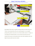
Remove the packing tape that was used to secure the low profile access lid and raise the cover.
Unscrew and remove head protection.
Release the Green shipping tab lock located at the base of the Print Carriage.
Remove screws to unblock table.
Plug the Unit into AC Power
Insert the AC cord into the unit and plug the opposite end into a power strip with surge
protection. Avoid plugging multiple items into the same power strip.
This machine has a main power switch, IR lamp power and a sub power switch. When using the
machine, you switch all on in this sequence: first heather, then printer and last the sub power.
Use IR lamp control to turn on the lamp only during printing. At all other time IR lamp
must be off.
1
2
Main power and IR lamp power switch
IR lamp control
Use IR lamp control to turn on the lamp only during printing. At all other time IR
lamp must be off.
3
Sub power switch
After powering on, Non-Genuine Message appears on LCD Display.
Preparing and Filling system with ink
Wait until the message in the LCD display shows “Ready”.
1. The Ink cartridges are numbered from 1-8. Using these
numbers as a guide, place the sealed Ink cartridges into
your Azon DTS and lower both blue levers to secure
them in place.
2. You must perform a Power Cleaning during setup to ensure ink is proper flowing
through the ink lines.
After every Power Cleaning always empty waste container.
Power Cleanings are executed from the LCD Display Panel.
With the printer in Ready status on the LCD Display Panel
located above the White ink cartridge press the RIGHT ARROW
once.
Press the UP ARROW and scroll through the menu items until
you come to "Maintenance." Press the RIGHT ARROW once.
Press the DOWN ARROW to scroll the menu items until you
come to "Power Clean." To execute a Power Cleaning, press
the RIGHT ARROW once. Confirm Power Cleaning by pressing
RIGHT ARROW again. Abort it with LEFT ARROW.
The LCD display will inform you of the Power Cleaning's status in percentages. At the
10% mark, the display will prompt you to move both blue levers into the UP position.
At the 20% mark, you will be prompted to move both blue levers into the DOWN position.
You will again be prompted to move both levers at the 30%, 40% and 50% marks. At the
50% point, both levers will be in the DOWN position and you will not have to adjust them
again during the power cleaning cycle.
Once the Power Cleaning is complete, the LCD Display will read "Ready."
Perform one more Power Cleanings.
Connecting to the Network
Make sure you have the correct cable for connecting the printer. To connect to a network switch
or hub, you need a standard RJ-45 “straight-through” network cable. To connect directly to your
computer’s network interface, you need an RJ-45 crossover cable.
1
Connect one end of the appropriate cable to the printer’s Ethernet port. Then connect
the other end to your network switch or hub or your computer’s Ethernet port.
2
Once the printer is connected to your network, you need to configure it.
Configuring the Network Interface
A Printer Driver is software needed to make any printer function. For your Azon DTS to operate
properly, you will need to install driver from DTS CD.
1. Run EPSetup.exe from folder Printer Driver. On Main Window select Epson Stylus Pro
4880C.
2. Select Set up the printer via a network connection
3. Select your printer and skip test page printing.
Now your Printer Driver is installed and your printer is connected to computer. Finish installation
and return to main window.
4. From the main window select Epson LFP Remote Panel
The LFP Remote Panel is a standalone application designed to give you several utility
functions, including the Nozzle Check and Power Cleaning utilities, right from your
computer. The alignment procedure is also completed by using the Epson LFP Remote
Panel.
5. Select Stylus Pro 4880
Finish installation and press exit on main window. Reboot printer.
Print Head Alignment
In addition to the initial setup requirements, it may be necessary to perform a Print Head
Alignment on other occasions such as:
•
•
•
If the Print Head makes contact with any object
If your prints contain vertical lines or misaligned parts of an image
If you see banding of any kind
Please be aware, should the Print Head make contact with ANY solid surface, it may be
permanently damaged and require replacement.
Performing a Head Alignment on an Azon DTS will require approximately 15-30 minutes. Before
beginning this procedure ensure you are familiar with all the required steps, as well as having
the necessary time to complete the process. Once you have begun a Head Alignment you
CANNOT exit the function without shutting down the machine. In addition, early exit may result
in severe misalignment of the Print Head or other operational concerns. Initial setup may require
2-3 alignment procedures to be completed.
It is necessary during setup to set and adjust the Calibration Plate to the proper height for output.
In addition, should you need to raise or lower the Calibration Plate to accommodate optimum
height for output, the following procedure would be used:
•
Place the Calibration Plate on top of and to the front and right edge (facing printer) of
your Plate guide. Secure Calibration Plate in place with double side tape.
•
Press ↓ down button on printer control panel. This will lift plate guide with calibration
plate up. Safety switch will stop plate movement. At this point calibration plate is too
far from print head.
•
Press memory button on printer control panel twice.
•
This will continue lifting table up.
•
When Calibration Plate reach maximum height, sensor return it automatically. Press
memory button again to stop movement.
•
For your security, check plate height manually. Lift the printer cover if it is not already.
Locate the Carriage Release button press and manually move the Print Carriage until its sits
near the center of Calibration Plate.
Carriage Release Button
•
Use the Platen Height Adjustment arrows on Control Panel to fine tune and set Print
Head clearance of approximately 2 - 3 mm. For bi-direction printing head clearance
must be 2 – 3 mm.
•
Slide the Print Carriage back to the capping station
•
Return to the CP and press → button. This will move the Calibration Plate to the rear. Place
the Platen so that it’s leading edge is just inside the Printing Head Unit.
Perform a Nozzle Check
You must print a Nozzle Check to ensure the Print Head is performing properly.
To initiate a Nozzle Check:
1. On the CP check that you are OFFLINE.
2. On Control Panel, press the RIGHT ARROW once and the display will read
"Printer Setup." Press the DOWN ARROW once to see "Test Print."
3. Press the RIGHT ARROW button once to see "Nozzle Check." Press the RIGHT
ARROW again and "Print" will appear in the display.
4. To execute the Nozzle Check, press the RIGHT ARROW button once.
•
If the Nozzle Check does not print correctly, perform a regular Head Cleaning. This is done
by holding down the RIGHT ARROW button for 3 seconds. After the Head Cleaning has
been completed, execute another Nozzle Check.
Before start printing you have to perform Nozzle Check. After rebooting your printer you
must also have to perform Nozzle Check prior printing.
Use normal white paper on the top of calibration plate for nozzle check printing.
Perform a Print Head Alignment.
1. Ensure that the gap between the top of the Calibration Plate and the Print Head is at minimum:
use the Up and Down buttons to adjust the height of the Printing Bed (with printing sheet on the
Platen) Press the Online button to move the Plate to the back position.
2. The DTS can only perform one “Dot Size” at a time. You will need to reload the media a total of
three times per alignment. A single Head Alignment procedure consists of 3 “Dot Sizes”.
3. On the CP check that you are ONLINE.
ONLINE
OFFLINE
There are 2 types of alignments: Uni-Directional and Bi-Directional. Uni-Directional aligns the
Print Head for printing one way (forward) across the garment, while Bi-Directional aligns the
Print Head for printing forward and backward.
Bi Directional Alignment
The following steps will cover sending the Print Head Alignment Test Print to the DTS
through the Epson LFP Remote Panel.
1. Open the LFP Remote Panel by double-clicking on the Epson LFP icon on your
Desktop.
If not present, using your Start menu, select Programs > Epson > Epson LFP Remote Panel.
2. From the main Window, select your printer
from the drop down menu.
3. Next, select Media Adjustment from the list
of icons in the Remote Panel window.
4. From the Media Adjustment screen select
Auto Adjustment Icon.
5.
In Auto Adjustment window select Other
for Media Type, enter 2 for Paper
Thichness and select Standard from
Platen Gap drop down menu.
6. Within the
Auto BiDirectional Alignment screens, place
a check mark in the first of the three boxes
ONLY, below Dot Size.You will have to
repeat the entire process two ADDITIONAL
times, placing check marks in Dot Size 2
the second time and Dot Size 3 the third.
WARNING: It is EXTREMELY crucial that you only
select ONE Dot Size per printout! The DTS does
not have enough calibration plate to print out all dot
sizes in one run. If you do not deselect the other
two check boxes, the printer will error out.
Press the Print button on the LFPRemote Panel
Screen.
After the print is complete, be careful not to
smudge the ink, it will be wet for a short while
Uni Directional Alignment
The following steps will cover sending the Print Head Alignment Test Print to the DTS
through the Epson LFP Remote Panel.
1. Open the LFP Remote Panel by double-clicking on the Epson LFP icon on your
Desktop.
If not present, using your Start menu, select Programs > Epson > Epson LFP Remote Panel.
2. From the main Window, select your printer
from the drop down menu.
3. Next, select Media Adjustment from the list
of icons in the Remote Panel window.
4. From the Media Adjustment screen select
Auto Adjustment Icon.
5.
In Auto Adjustment window select Other
for Media Type, enter 2 for Paper
Thichness and select Standard from
Platen Gap drop down menu.
6. Within the Auto UniDirectional Alignment
screens, place a check mark in the first of
the three boxes ONLY, below Dot Size.You
will have to repeat the entire process two
ADDITIONAL times, placing check marks in
Dot Size 2 the second time and Dot Size 3
the third.
WARNING: It is EXTREMELY crucial that you only
select ONE Dot Size per printout! The DTS does
not have enough calibration plate to print out all dot
sizes in one run. If you do not deselect the other
two check boxes, the printer will error out.
Press the Print button on the LFPRemote Panel
Screen.
After the print is complete, be careful not to
smudge the ink, it will be wet for a short while
Printing with the Azon DTS
Default settings in the printer driver
From your windows start menu choose and open “Devices and Printers”. In the upcoming window right
click on the “Stylus Pro 4880C (Network)” and choose Printing Preferences.
Click on the tab “Utility”. On the following screen press Export or Import icon. Press Import tab,
navigate or browse DTS driver settings on DTS CD and import it:
Select Uni or Bi printing direction, depending on printing material
Nozzle Check
You must print a Nozzle Check to ensure the Print Head is performing properly. You may use common
plain paper for this test.
To initiate a Nozzle Check:
1. Place plain paper on DTS table, taking care to align it with
print head, right hand corner (as you face the
front of the printer) and between sensors.
2. Adjust the Print Bed (or Platen) to the proper height for
output. Press ↓ button on control panel. The Print Bed will
stopped at proper height for output
3. On the CP check that you are OFFLINE.
4. On Control Panel, press the RIGHT ARROW once and the display will read
"Printer Setup." Press the DOWN ARROW once to see "Test Print."
5. Press the RIGHT ARROW button once to see "Nozzle Check." Press the RIGHT
ARROW again and "Print" will appear in the display.
6. To execute the Nozzle Check, press the RIGHT ARROW button once.
•
If the Nozzle Check does not print correctly, perform a regular Head Cleaning. This is done by
holding down the RIGHT ARROW button for 3 seconds. After the Head Cleaning has been
completed, execute another Nozzle Check.
Print Position and Head Height Adjustment
It is necessary during setup to adjust the Print Bed (or Platen) to the proper height for output. In
addition, should you need to raise or lower the Platen to accommodate different material heights, the
following procedure would be used:
The print does always start from the front end of the machine bed. Internal sensors position the printer
and guarantee that the images will always be printed in the same position.
To find out where the objects must be placed, it is necessary to pre print on paper. This print out can be
used to accurately position the print items or trays with your prepared media.
•
For print head height adjustment always place material your wanna print near the sensor
mark with yellow arrow.
•
Press down arrow ↓ button on control panel. This will lift table up. The sensor will
automatically stop table movement at right distance from print head.
•
For your security check table height manually. Lift the printer cover if it is not already. Locate
the Carriage Release button press and manually move the Print Carriage until its sits over
the material for printing.
Carriage Release Button
•
Use the Platen Height Adjustment arrows on Control Panel to fine tune and set a Print
Head clearance of approximately 2 - 3 mm. For bi-direction printing head clearance
must be 2 – 3 mm.
•
Slide the Print Carriage back to the capping station
Preheating Materials for Print
Once the material is positioned and ready for printing, it is necessary to preheat some materials.
Adjust IR lamp according to recommended settings in table. When IR lamp
reaches desired value, preheat material 30 seconds prior printing. IR lamp
should me on during printing. After printing turn IR lamp immediately.
IR lamp must be turned off after every print.
Material Needs
Primer
Printing Resolution
and Direction
IR Lamp Settings
(depending of material
thicknes)
Post prining Material
Fixation
Acrylic acid resin
no
1440*720 dpi bi
20
no
ABS resin
no
1440*720 dpi bi
20
no
Polycarbonate
no
1440*720 dpi bi
20
no
PET
no
1440*720 dpi bi
20
no
Vinyl
no
1440*720 dpi bi
20
no
Plastic Corrugated
Cardboard
no
1440*720 dpi bi
20
no
Aluminum Compound
Plate
yes
1440*720 dpi bi
20
yes for better
abrassion resistance
Soft Wrapping Materials
no
1440*720 dpi bi
20
no
Other Resin
no
1440*720 dpi bi
20
no
Aluminum Plate
yes
1440*720 dpi bi
20
SUS
no
1440*720 dpi bi
20
yes for better
abrassion resistance
Brass
no
1440*720 dpi bi
20
yes for better
abrassion resistance
Paper and Corrugated
Cardboard
no
1440*720 dpi bi
20
Leather Skin
no
1440*720 dpi bi
20
no
Building Materials
no
1440*720 dpi bi
20
no
Wood
no
1440*720 dpi bi
20
no
Glass
no
1440*720 dpi uni
20
yes for better
abrassion resistance
Aluminum-Plastic
Composite Board
no
1440*720 dpi bi
yes for better
abrassion resistance
Anodized Aluminium
no
1440*720 dpi bi
Salt Bath
Stainless Steal
no
1440*720 dpi uni
yes for better
abrassion resistance
How to print using Windows or Mac applications
When the material is ready for printing you can use the print dialog from your Windows or Mac
application (e.g. Photoshop, CorelDraw or Illustrator) to start the printing process. Follow the on screen
instructions to start the print out.
A Word about Resolutions, Speed and Quality
The resolution you choose will not only determine print quality, but print speed as well. If you use a
lower resolution Print Mode, you will achieve a much faster print speed, but may not get the quality
needed for photo images. Lower resolutions apply fewer ink dots per inch (DPI), which allows the Print
Head to move much faster.
If you use higher resolution Print Modes, you will notice a decrease in print speed but an improvement
in image quality. A higher DPI increases print quality by increasing the density of the dots per inch.
Therefore, we recommend a lower resolution for cartoon images, but a higher resolution for photo type
images.
When a Printing Job Is Finished
We recommend using Acrylic or Urethane post treatment compatible with Azon DTS Ink.