1
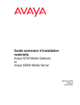
Quick Start for Hardware Installation:
Avaya G700 Media Gateway
and
Avaya S8300 Media Server
555-233-150
Issue 4
June 2004
Copyright 2004, Avaya Inc.
All Rights Reserved
Notice
Every effort was made to ensure that the information in this document
was complete and accurate at the time of printing. However,
information is subject to change.
Warranty
Avaya Inc. provides a limited warranty on this product. Refer to your
sales agreement to establish the terms of the limited warranty. In
addition, Avaya’s standard warranty language as well as information
regarding support for this product, while under warranty, is available
through the following Web site: http://www.avaya.com/support.
Preventing Toll Fraud
“Toll fraud” is the unauthorized use of your telecommunications
system by an unauthorized party (for example, a person who is not a
corporate employee, agent, subcontractor, or is not working on your
company's behalf). Be aware that there may be a risk of toll fraud
associated with your system and that, if toll fraud occurs, it can result
in substantial additional charges for your telecommunications
services.
Avaya Fraud Intervention
If you suspect that you are being victimized by toll fraud and you need
technical assistance or support, in the United States and Canada, call
the Technical Service Center's Toll Fraud Intervention Hotline at
1-800-643-2353.
How to Get Help
For additional support telephone numbers, go to the Avaya support
Web site: http://www.avaya.com/support. If you are:
• Within the United States, click the Escalation Management link.
Then click the appropriate link for the type of support you need.
• Outside the United States, click the Escalation Management link.
Then click the International Services link that includes telephone
numbers for the international Centers of Excellence.
Providing Telecommunications Security
Telecommunications security (of voice, data, and/or video
communications) is the prevention of any type of intrusion to (that is,
either unauthorized or malicious access to or use of) your company's
telecommunications equipment by some party.
Your company's “telecommunications equipment” includes both this
Avaya product and any other voice/data/video equipment that could be
accessed via this Avaya product (that is, “networked equipment”).
An “outside party” is anyone who is not a corporate employee, agent,
subcontractor, or is not working on your company's behalf. Whereas, a
“malicious party” is anyone (including someone who may be
otherwise authorized) who accesses your telecommunications
equipment with either malicious or mischievous intent.
Such intrusions may be either to/through synchronous (timemultiplexed and/or circuit-based) or asynchronous (character-,
message-, or packet-based) equipment or interfaces for reasons of:
• Utilization (of capabilities special to the accessed equipment)
• Theft (such as, of intellectual property, financial assets, or toll
facility access)
• Eavesdropping (privacy invasions to humans)
• Mischief (troubling, but apparently innocuous, tampering)
• Harm (such as harmful tampering, data loss or alteration,
regardless of motive or intent)
Be aware that there may be a risk of unauthorized intrusions
associated with your system and/or its networked equipment. Also
realize that, if such an intrusion should occur, it could result in a
variety of losses to your company (including but not limited to,
human/data privacy, intellectual property, material assets, financial
resources, labor costs, and/or legal costs).
Responsibility for Your Company’s Telecommunications Security
The final responsibility for securing both this system and its
networked equipment rests with you - Avaya’s customer system
administrator, your telecommunications peers, and your managers.
Base the fulfillment of your responsibility on acquired knowledge and
resources from a variety of sources including but not limited to:
•
•
•
•
•
•
Installation documents
System administration documents
Security documents
Hardware-/software-based security tools
Shared information between you and your peers
Telecommunications security experts
To prevent intrusions to your telecommunications equipment, you and
your peers should carefully program and configure:
• Your Avaya-provided telecommunications systems and their
interfaces
• Your Avaya-provided software applications, as well as their
underlying hardware/software platforms and interfaces
• Any other equipment networked to your Avaya products
TCP/IP Facilities
Customers may experience differences in product performance,
reliability and security depending upon network configurations/design
and topologies, even when the product performs as warranted.
Standards Compliance
Avaya Inc. is not responsible for any radio or television interference
caused by unauthorized modifications of this equipment or the
substitution or attachment of connecting cables and equipment other
than those specified by Avaya Inc. The correction of interference
caused by such unauthorized modifications, substitution or attachment
will be the responsibility of the user. Pursuant to Part 15 of the Federal
Communications Commission (FCC) Rules, the user is cautioned that
changes or modifications not expressly approved by Avaya Inc. could
void the user’s authority to operate this equipment.
Product Safety Standards
This product complies with and conforms to the following
international Product Safety standards as applicable:
Safety of Information Technology Equipment, IEC 60950, 3rd Edition
including all relevant national deviations as listed in Compliance with
IEC for Electrical Equipment (IECEE) CB-96A.
Safety of Information Technology Equipment, CAN/CSA-C22.2
No. 60950-00 / UL 60950, 3rd Edition
Safety Requirements for Customer Equipment, ACA Technical
Standard (TS) 001 - 1997
One or more of the following Mexican national standards, as
applicable: NOM 001 SCFI 1993, NOM SCFI 016 1993, NOM 019
SCFI 1998
The equipment described in this document may contain Class 1
LASER Device(s). These devices comply with the following
standards:
• EN 60825-1, Edition 1.1, 1998-01
• 21 CFR 1040.10 and CFR 1040.11.
The LASER devices operate within the following parameters:
• Maximum power output: -5 dBm to -8 dBm
• Center Wavelength: 1310 nm to 1360 nm
Luokan 1 Laserlaite
Klass 1 Laser Apparat
Use of controls or adjustments or performance of procedures other
than those specified herein may result in hazardous radiation
exposures. Contact your Avaya representative for more laser product
information.
Electromagnetic Compatibility (EMC) Standards
This product complies with and conforms to the following
international EMC standards and all relevant national deviations:
Limits and Methods of Measurement of Radio Interference of
Information Technology Equipment, CISPR 22:1997 and
EN55022:1998.
Information Technology Equipment – Immunity Characteristics –
Limits and Methods of Measurement, CISPR 24:1997 and
EN55024:1998, including:
•
•
•
•
•
•
•
•
•
Electrostatic Discharge (ESD) IEC 61000-4-2
Radiated Immunity IEC 61000-4-3
Electrical Fast Transient IEC 61000-4-4
Lightning Effects IEC 61000-4-5
Conducted Immunity IEC 61000-4-6
Mains Frequency Magnetic Field IEC 61000-4-8
Voltage Dips and Variations IEC 61000-4-11
Powerline Harmonics IEC 61000-3-2
Voltage Fluctuations and Flicker IEC 61000-3-3
Federal Communications Commission Statement
Part 15:
Note: This equipment has been tested and found to comply with
the limits for a Class A digital device, pursuant to Part 15 of the
FCC Rules. These limits are designed to provide reasonable
protection against harmful interference when the equipment is
operated in a commercial environment. This equipment generates,
uses, and can radiate radio frequency energy and, if not installed
and used in accordance with the instruction manual, may cause
harmful interference to radio communications. Operation of this
equipment in a residential area is likely to cause harmful
interference in which case the user will be required to correct the
interference at his own expense.
Avaya attests that this registered equipment is capable of providing
users access to interstate providers of operator services through the use
of access codes. Modification of this equipment by call aggregators to
block access dialing codes is a violation of the Telephone Operator
Consumers Act of 1990.
REN Number
For MCC1, SCC1, CMC1, G600, and G650 Media Gateways:
This equipment complies with Part 68 of the FCC rules. On either the
rear or inside the front cover of this equipment is a label that contains,
among other information, the FCC registration number, and ringer
equivalence number (REN) for this equipment. If requested, this
information must be provided to the telephone company.
For G350 and G700 Media Gateways:
This equipment complies with Part 68 of the FCC rules and the
requirements adopted by the ACTA. On the rear of this equipment is a
label that contains, among other information, a product identifier in
the format US:AAAEQ##TXXXX. The digits represented by ## are
the ringer equivalence number (REN) without a decimal point (for
example, 03 is a REN of 0.3). If requested, this number must be
provided to the telephone company.
For all media gateways:
The REN is used to determine the quantity of devices that may be
connected to the telephone line. Excessive RENs on the telephone line
may result in devices not ringing in response to an incoming call. In
most, but not all areas, the sum of RENs should not exceed 5.0. To be
certain of the number of devices that may be connected to a line, as
determined by the total RENs, contact the local telephone company.
REN is not required for some types of analog or digital facilities.
Means of Connection
Connection of this equipment to the telephone network is shown in the
following tables.
For MCC1, SCC1, CMC1, G600, and G650 Media Gateways:
Manufacturer’s Port
Identifier
FIC Code
SOC/REN/ Network
A.S. Code Jacks
Off premises station
OL13C
9.0F
RJ2GX,
RJ21X,
RJ11C
DID trunk
02RV2-T
0.0B
RJ2GX,
RJ21X
CO trunk
02GS2
0.3A
RJ21X
02LS2
0.3A
RJ21X
Tie trunk
TL31M
9.0F
RJ2GX
Basic Rate Interface
02IS5
6.0F, 6.0Y
RJ49C
1.544 digital interface
04DU9-BN
6.0F
RJ48C,
RJ48M
04DU9-IKN
6.0F
RJ48C,
RJ48M
04DU9-ISN
6.0F
RJ48C,
RJ48M
04DU9-DN
6.0Y
RJ48C
Part 68: Answer-Supervision Signaling
Allowing this equipment to be operated in a manner that does not
provide proper answer-supervision signaling is in violation of Part 68
rules. This equipment returns answer-supervision signals to the public
switched network when:
• answered by the called station,
• answered by the attendant, or
• routed to a recorded announcement that can be administered by
the customer premises equipment (CPE) user.
This equipment returns answer-supervision signals on all direct
inward dialed (DID) calls forwarded back to the public switched
telephone network. Permissible exceptions are:
• A call is unanswered.
• A busy tone is received.
• A reorder tone is received.
120A4 channel service unit
Declarations of Conformity
For G350 and G700 Media Gateways:
Manufacturer’s Port
Identifier
FIC Code
SOC/REN/ Network
A.S. Code Jacks
Ground Start CO trunk
02GS2
1.0A
RJ11C
DID trunk
02RV2-T
AS.0
RJ11C
Loop Start CO trunk
02LS2
0.5A
RJ11C
1.544 digital interface
04DU9-BN
6.0Y
RJ48C
Basic Rate Interface
04DU9-DN
6.0Y
RJ48C
04DU9-IKN
6.0Y
RJ48C
04DU9-ISN
6.0Y
RJ48C
02IS5
6.0F
RJ49C
For all media gateways:
If the terminal equipment (for example, the media server or media
gateway) causes harm to the telephone network, the telephone
company will notify you in advance that temporary discontinuance of
service may be required. But if advance notice is not practical, the
telephone company will notify the customer as soon as possible. Also,
you will be advised of your right to file a complaint with the FCC if
you believe it is necessary.
The telephone company may make changes in its facilities, equipment,
operations or procedures that could affect the operation of the
equipment. If this happens, the telephone company will provide
advance notice in order for you to make necessary modifications to
maintain uninterrupted service.
If trouble is experienced with this equipment, for repair or warranty
information, please contact the Technical Service Center at
1-800-242- 2121 or contact your local Avaya representative. If the
equipment is causing harm to the telephone network, the telephone
company may request that you disconnect the equipment until the
problem is resolved.
A plug and jack used to connect this equipment to the premises wiring
and telephone network must comply with the applicable FCC Part 68
rules and requirements adopted by the ACTA. A compliant telephone
cord and modular plug is provided with this product. It is designed to
be connected to a compatible modular jack that is also compliant. It is
recommended that repairs be performed by Avaya certified
technicians.
The equipment cannot be used on public coin phone service provided
by the telephone company. Connection to party line service is subject
to state tariffs. Contact the state public utility commission, public
service commission or corporation commission for information.
United States FCC Part 68 Supplier’s Declaration of Conformity
(SDoC)
Avaya Inc. in the United States of America hereby certifies that the
equipment described in this document and bearing a TIA TSB-168
label identification number complies with the FCC’s Rules and
Regulations 47 CFR Part 68, and the Administrative Council on
Terminal Attachments (ACTA) adopted technical criteria.
Avaya further asserts that Avaya handset-equipped terminal
equipment described in this document complies with Paragraph
68.316 of the FCC Rules and Regulations defining Hearing Aid
Compatibility and is deemed compatible with hearing aids.
Copies of SDoCs signed by the Responsible Party in the U. S. can be
obtained by contacting your local sales representative and are
available on the following Web site: http://www.avaya.com/support.
All Avaya media servers and media gateways are compliant with FCC
Part 68, but many have been registered with the FCC before the SDoC
process was available. A list of all Avaya registered products may be
found at: http://www.part68.org by conducting a search using “Avaya”
as manufacturer.
European Union Declarations of Conformity
Avaya Inc. declares that the equipment specified in this document
bearing the “CE” (Conformité Europeénne) mark conforms to the
European Union Radio and Telecommunications Terminal Equipment
Directive (1999/5/EC), including the Electromagnetic Compatibility
Directive (89/336/EEC) and Low Voltage Directive (73/23/EEC). This
equipment has been certified to meet CTR3 Basic Rate Interface (BRI)
and CTR4 Primary Rate Interface (PRI) and subsets thereof in CTR12
and CTR13, as applicable.
Copies of these Declarations of Conformity (DoCs) can be obtained
by contacting your local sales representative and are available on the
following Web site: http://www.avaya.com/support.
Japan
This is a Class A product based on the standard of the Voluntary
Control Council for Interference by Information Technology
Equipment (VCCI). If this equipment is used in a domestic
environment, radio disturbance may occur, in which case, the user
may be required to take corrective actions.
This equipment, if it uses a telephone receiver, is hearing aid
compatible.
Canadian Department of Communications (DOC) Interference
Information
This Class A digital apparatus complies with Canadian ICES-003.
Cet appareil numérique de la classe A est conforme à la norme
NMB-003 du Canada.
This equipment meets the applicable Industry Canada Terminal
Equipment Technical Specifications. This is confirmed by the
registration number. The abbreviation, IC, before the registration
number signifies that registration was performed based on a
Declaration of Conformity indicating that Industry Canada technical
specifications were met. It does not imply that Industry Canada
approved the equipment.
To order copies of this and other documents:
Call:
Avaya Publications Center
Voice 1.800.457.1235 or 1.207.866.6701
FAX 1.800.457.1764 or 1.207.626.7269
Write:
Globalware Solutions
200 Ward Hill Avenue
Haverhill, MA 01835 USA
Attention: Avaya Account Management
E-mail:
[email protected]
For the most current versions of documentation, go to the Avaya
support Web site: http://www.avaya.com/support.
Contents
Contents
1
Before You Go to the Installation Site
7
• Other documents
7
• License file, software, and firmware
7
• Laptop requirements
8
2
Conduct Equipment Inventory
9
3
Mount Media Gateway
13
4
Install Octaplane Stacking Module
15
5
Connect Media Gateways
16
6
Install S8300 Media Server
18
7
Install Media and Expansion Modules
20
8
Install USB Modem and CD-ROM Drive
21
9
Install UPS and Apply Power
22
10 Connect the Laptop — G700 without an S8300
23
11 Connect the Laptop — G700 with S8300
25
Quick Start: G700 and S8300
June 2004
5
Contents
6
Quick Start: G700 and S8300
June 2004
Before You Go to the Installation Site
Other documents
1
Before You Go to the Installation
Site
The following activities must be completed before going to an installation site.
Other documents
Obtain access to the following documentation:
• The G700/S8300 Installation guide: Installation and Upgrades for Avaya G700 Media Gateway
and Avaya S8300 Media Server, 555-234-100.
• The documentation library on CD, installed on your laptop, or accessible from the Avaya Support
web site: Documentation for Avaya Communication Manager, Media Gateways and Servers,
555-300-151.
License file, software, and firmware
The following tasks must be completed before you can install an Avaya S8300 Media Server and Avaya
G700 Media Gateway.
1
Meet with the customer to complete the Electronic Preinstallation Worksheet. The Electronic
Preinstallation Worksheet contains specific information about the customer’s network
configuration and telephony requirements. This information is required to use the Avaya
Installation Wizard to configure the Avaya IP solution.
NOTE:
To use the Avaya Installation Wizard, Release 2.0 or later of the Communication Manager
must be installed on the media server. If a pre-2.0 release of the Communication Manager
is installed on the media server, the software must be upgraded before the Avaya
Installation Wizard can be used.
NOTE:
The current release of the Avaya Installation Wizard supports only an English-language
operating system.
2
If you are using the Avaya Installation Wizard to generate basic translations on an S8300 primary
controller in a G700, get the customer’s Name and Number list file and the Custom Templates.
Copy these files to your laptop. The Electronic Preinstallation Worksheet contains instructions for
the Name/Number and Custom Templates files.
Quick Start: G700 and S8300
June 2004
7
Before You Go to the Installation Site
Laptop requirements
3
Complete the following steps to retrieve the required license files and password files from
Remote Feature Activation (RFA):
• For an S8300 configured as a primary controller, one license file.
• If you are using the Avaya Installation Wizard to generate basic translations on an S8300
primary controller, you need to retrieve two license files:
— Generate one license file with FEAT_DADMIN turned on by selecting
FEAT_DADMIN on the RFA Features screen.
— Generate a second license file with FEAT_DADMIN turned off by clearing the
FEAT_DADMIN selection on the RFA Features screen. The Modify System
Record function is used to create the second license file. This step is not required
for installations completed by Avaya authorized dealer technicians.
NOTE:
Each license file must be labeled carefully because the files will be used at different points
in the installation process.
• Retrieve the password (authentication) file.
4
5
Obtain the most recent versions of software and firmware on CD-ROM.
6
The technician will be advised if ProVision will be used in addition to the Avaya Installation
Wizard. ProVision can be used to upload all of the Communication Manager translations.
Information on the Avaya Installation Wizard options for ProVision is in the Electronic
Preinstallation Worksheet.
If necessary for your installation, obtain a USB CD-ROM drive for use at the site. This drive is
not necessary if you have TFTP server installed on your laptop.
Laptop requirements
The laptop PC that you use to access the S8300 and/or G700 and to launch the Avaya Installation Wizard
must meet the following requirements:
•
•
•
•
A minimum display resolution of 800 by 600
10/100 ethernet card installed
Windows 95 or later
Internet Explorer 5.0 or later
Once you have verified that all the above activities are completed, you can begin product hardware
installation following the instructions in this guide.
8
Quick Start: G700 and S8300
June 2004
Conduct Equipment Inventory
2
Conduct Equipment Inventory
The following list of equipment contains items that may not be needed for your configuration — those
items are specified as "optional" and may not be included in your inventory.
ALM PWR CPU MSTR
LNK COL Tx
Rx
51
52
53
54
55
56
57
58
59
60
61
62
63
64
65
66
Avaya G700 Media Gateway Chassis
V2
EXT1 EXT2
FDX FC Hspd LAG
V3
V1
V4
EXT1
EXT2
Optional Avaya S8300B Media Server
ALM
TST
ACT
OK TO
REMOVE
SHUT DOWN
SERVICES
ALM
TST
ACT
SIG
SO
EI
SM
EM
SI
USB1
USB2
Optional Avaya MM710 T1/E1 Media Module
EO
EIA 530A DCE
E1/T1
Optional Avaya MM711 Analog Media Module
AVAYA
ALM
TST
ACT
1
2
3
4
5
6
7
NOTE:
8
The Analog and the DCP media
modules look similar. Check their
labels to verify the module type.
AVAYA
ALM
TST
ACT
1
2
3
4
5
6
7
Optional Avaya MM712
DCP Media Module
8
NOTE:
The DCP and the Analog media
modules look similar. Check their
labels to verify the module type.
ALM
TST
ACT
AVAYA
Optional Avaya MM760 VoIP Media Module
Optional Avaya MM714 4FXS x 4FXO Analog
Media Module
ALM
TST
ACT
Optional Avaya MM717 24-port DCP Media
Module.
NOTE:
Endpoints connected to this media
module must be in-building only.
Optional Avaya MM722 2-port BRI Media Module
Quick Start: G700 and S8300
June 2004
9
Conduct Equipment Inventory
51
52
53
54
55
56
57
58
59
60
61
62
63
64
65
66
X330T16
Optional Expansion Module.
Optional X330STK Octaplane
Stacking Module.
Optional Avaya IA770 Messaging Module.
Optional USB modem.
Material ID: 700277551
Optional Teac USB CD-ROM Drive.
Material ID: 700289580.
Optional Uninterruptable Power Supply (UPS) for
AC-Powered Gateways Only.
NOTE:
A stand-alone version of the UPS is
shown.
10
Quick Start: G700 and S8300
June 2004
Conduct Equipment Inventory
Screw Packet and Rack Mount Brackets
For each bracket:
• three flat-head machine screws attach the
bracket to the G700
• two round-head lock-washer machine screws
attach the bracket to the rack
NOTE:
There are four sizes of lock-washer
screws in the packet for attaching the
brackets to the rack. Use the
appropriate size screws to match the
specific hole size of the rack.
Optional X330SC Short Cable.
NOTE:
The X3300SC Short Cable is
sometimes shipped attached to the
X3300STK Octaplane Stacking
Module.
Optional X3300RC Redundancy Cable.
Optional X3300 LC Long Cable.
Optional USB Cable and Adapter for use with the
USB modem.
Quick Start: G700 and S8300
June 2004
11
Conduct Equipment Inventory
Crossover Ethernet Cable (CAT5)
Serial or "Console" Cable and Adapter
Ground wire.
Optional AC Power Cord
Optional DC Power Cord.
Feet used for table mounting.
12
Quick Start: G700 and S8300
June 2004
Mount Media Gateway
3
Mount Media Gateway
1
Wear an anti-static ground wrist strap and
attach to an approved ground.
2
For rack mount, install the mounting brackets
on the left and right sides of the gateway
chassis using the flathead screws from the
bracket packet.
NOTE:
The brackets can also be installed in
the middle of the chassis.
3
Lift the media gateway chassis and mount in
a rack using two lock-washer screws for each
bracket.
CAUTION:
The weight of the media gateway is
unevenly distributed and may require
two persons to mount in the rack.
ALM PWR CPU MSTR
LNK COL Tx
Rx
51
52
53
54
55
56
57
58
59
60
61
62
63
64
65
66
V2
EXT1 EXT2
FDX FC Hspd LAG
V3
V1
4
For desktop mount. Install feet using plastic
push rivets.
V4
EXT1
EXT2
Quick Start: G700 and S8300
June 2004
13
Mount Media Gateway
14
5
Connect the ground wire to the ground
conductor on the back of the media gateway.
6
Attach the other end of the ground wire to an
approved ground.
Quick Start: G700 and S8300
June 2004
Install Octaplane Stacking Module
4
Install Octaplane Stacking Module
NOTE:
Complete these steps only if you are connecting more than one G700 Media Gateway in a
stack configuration.
1
Remove the blank faceplate from the
Octaplane slot on the back of the media
gateway.
2
Align the X330STK Octaplane
Stacking Module with the interior
guides and insert until firmly seated
! WARNING:
To prevent damage to
equipment, handle the module
by the faceplate or edge.
3
Quick Start: G700 and S8300
June 2004
Tighten the captive screws.
15
Connect Media Gateways
5
Connect Media Gateways
NOTE:
Complete these steps only if you are connecting more than one G700 Media Gateway in a
stack configuration.
1
Using the gray X330SC short cables,
connect the media gateways from the
bottom up:
• Connect the light gray connector to
the port labeled “Cable to upper
unit.”
• Connect the dark gray connector to
the port labeled “Cable to lower
unit.”
• Repeat both steps until all units in
the stack are connected (maximum
of 10 units).
2
For single-stack redundancy, connect the
bottom unit and the top unit using the black
X330RC redundancy cable:
• Connect the light gray connector to
the port labeled “Cable to upper
unit: on the top unit of the stack.
• Connect the dark gray connector to
the port labeled “Cable to lower
unit” on the bottom unit of the stack.
Single-stack redundancy
16
Quick Start: G700 and S8300
June 2004
Connect Media Gateways
3
For multiple stack redundancy, connect the
stacks using the black X330RC redundancy
cable and the gray X330LC long cable:
• Connect the light gray connector of the
black X330RC redundancy cable to the port
labeled “Cable to upper unit” on the top unit
of the stack 2.
• Connect the dark gray connector of the
black X330RC redundancy cable to the port
labeled “Cable to lower unit” on the top unit
of the stack1.
• Connect the light gray connector of the gray
X3300LC long cable to the port labeled
“Cable to upper unit” on the top unit of the
stack 1.
• Connect the dark gray connector of the gray
X330LC long cable to the port labeled
“Cable to lower unit” on the bottom unit of
the stack 2.
Multiple-stack redundancy
Quick Start: G700 and S8300
June 2004
17
Install S8300 Media Server
6
Install S8300 Media Server
NOTE:
Complete these steps if you are installing an S8300 Media Server (configured as the
primary controller or as a Local Survivable Processor).
1
From the front of the G700 Media Gateway,
remove the blank faceplate from slot V1.
2
Remove the LED module (located above slot
V1) and place in an anti-static bag.
3
Optional. Using the instructions packaged
with the IA770 Messaging Module, attach the
IA770 module to the S8300 Media Server.
NOTE:
For small configurations, a softwarebased messaging feature may be
supported. This feature does not
require the IA770 Messaging Module
shown here.
AL
M
TS
ACT
OK T
RE TO
MO
VE
SH
UT
DO
WN
SE
RV
ICES
US
B1
US
B2
4
18
Align the S8300 Media Server with the lower
interior guides and insert about 2" into slot
V1.
Quick Start: G700 and S8300
June 2004
Install S8300 Media Server
5
Align the LED module with the upper interior
guides and insert until the faceplate is flush
with the S8300 Media Server.
6
Continue inserting both modules together
until firmly seated.
! WARNING:
Failure to seat both modules together
could result in equipment damage.
ALM PWR CPU MSTR
V1
ALM
TST
ACT
OK TO
REMOVE
LNK COL Tx
Rx
51
52
53
54
55
56
57
58
59
60
61
62
63
64
65
66
V2
EXT1 EXT2
FDX FC Hspd LAG
7
Tighten the captive screws on the S8300.
V3
SHUT DOWN
SERVICES
USB1
USB2
V4
EXT1
EXT2
Quick Start: G700 and S8300
June 2004
19
Install Media and Expansion Modules
7
Install Media and Expansion
Modules
NOTE:
In each gateway, a single expansion module can be installed in the lower left slot only. If
the S8300 is installed (in slot V1), up to 3 media modules can be installed in slots V2–V4.
If no S8300 is installed, a fourth media module can be installed in Slot V1.
20
1
To install a media module, first remove the
upper right blank faceplate.
2
Align the media module with the interior guides
and insert into slot until firmly seated.
3
4
Tighten the captive screws.
5
To install the expansion module, first remove
the lower left blank faceplate.
6
Align the expansion module with the interior
guides and insert into slot until firmly seated.
7
Tighten the captive screws.
Repeat steps 1 through 3 for each media module
to be installed.
Quick Start: G700 and S8300
June 2004
Install USB Modem and CD-ROM Drive
8
Install USB Modem and CD-ROM
Drive
USB Modem
1
Connect the USB cable to either of the two
USB port on the faceplate of the S8300.
2
Following the instructions packaged with the
modem, connect the other end of the USB
cable to the modem.
3
Connect the analog telephone line to the
RJ-11 jack on the modem.
Teac USB CD-ROM Drive
The USB CD-ROM drive is used primarily as a
software source location when remastering a S8300
hard drive.
1
Connect the USB cable into either of the two
USB ports on the faceplate of the S8300.
2
Connect the other end of the USB cable to the
CD-ROM drive.
NOTE:
If you have installed a TFTP server on
your laptop, you can use the your
laptop’s CD-ROM drive instead of the
external USB CD-ROM drive when
remastering the S8300 hard drive.
Quick Start: G700 and S8300
June 2004
21
Install UPS and Apply Power
9
Install UPS and Apply Power
UPS (AC only)
1
The UPS is an option for AC-powered
gateways only. From the back of the G700
Media Gateway, connect the Uninterruptable
Power Supply (UPS) using the
manufacturer’s instructions.
NOTE:
A stand-alone version of the UPS is
shown.
AC power
1
Apply power to each media gateway by
connecting the AC power cord.
NOTE:
There is no on/off switch. The units
will power up when connected.
DC power
1
Apply power to each media gateway by
connecting the DC power cord.
NOTE:
There is no on/off switch. The units
will power up when connected.
22
Quick Start: G700 and S8300
June 2004
Connect the Laptop — G700 without an S8300
10 Connect the Laptop — G700 without
an S8300
This section assumes the G700 does not contain an S8300 Media Server. Use the Gateway Installation
Wizard from the laptop to enter the initial gateway configuration parameters.
Quick Start: G700 and S8300
June 2004
1
Connect the RJ45 end of a serial cable
to the Console port on the lower right
of the front of the G700.
2
Connect the other end of the cable to
the Serial port on the laptop.
3
4
Power on the laptop.
5
Start the Gateway Installation Wizard
(GIW).
6
Follow the GIW instructions to Enter
the configuration parameters.
Start a Hyperterm (or similar
application) session.
23
Connect the Laptop — G700 without an S8300
ALM PWR CPU MSTR
LNK COL Tx
Rx
51
52
53
54
55
56
57
58
59
60
61
62
63
64
65
66
V2
EXT1 EXT2
FDX FC Hspd LAG
V3
V1
To connect to the customer’s LAN
1
Connect a straight Ethernet cable to
one of the Ethernet ports (labeled Ext
1 and Ext 2) on the front of the G700.
2
Connect the other end of the cable to a
LAN connector.
V4
EXT1
24
EXT2
Quick Start: G700 and S8300
June 2004
Connect the Laptop — G700 with S8300
11 Connect the Laptop — G700 with
S8300
This section assumes the G700 has an S8300 Media Server installed.
1
Connect a crossover Ethernet cable to the
Services port on the faceplate of the S8300
Media Server.
2
Connect the other end of the cable to the
Ethernet port on the laptop.
3
4
Power on the laptop.
Verify the Services network settings:
a IP Address: 192.11.13.5
b Subnet Mask: 255.255.255.252
c Domain Name Service (DNS):
disabled.
5
Open MS Internet Explorer and disable the
Proxy Server.
6
In the browser address field, initiate access to
the S8300 by typing in lower case:
http://192.11.13.6
7
8
Quick Start: G700 and S8300
June 2004
Click Continue to access the Logon page.
Click OK or Yes, as appropriate, for any
security pages that may appear prior to the
Logon page.
25
Connect the Laptop — G700 with S8300
9
10
Log in to the S8300 Media server with the
craft login and password for initial
installation.
Use the Avaya Installation Wizard. Click on
Launch Avaya Installation Wizard and
continue.
NOTE:
If you are not using the Avaya
Installation Wizard, refer to Installation
and Upgrades for Avaya G700 Media
Gateway and Avaya S8300,
555-234-100, for additional
instructions.
ALM PWR CPU MSTR
LNK COL Tx
Rx
51
52
53
54
55
56
57
58
59
60
61
62
63
64
65
66
V2
EXT1 EXT2
FDX FC Hspd LAG
V3
V1
To connect to the customer’s LAN
1
Connect a straight Ethernet cable to one of the
Ethernet ports (labeled Ext 1 and Ext 2) on the
front of the G700.
2
Connect the other end of the cable to a LAN
connector.
V4
EXT1
26
EXT2
Quick Start: G700 and S8300
June 2004
Connect the Laptop — G700 with S8300
To connect USB Modem
To configure the G700 and S8300 remotely, connect
the USB modem.
Quick Start: G700 and S8300
June 2004
1
Connect the USB cable to either of the two
USB port on the faceplate of the S8300.
2
Following the instructions packaged with the
modem, connect the other end of the USB
cable to the modem.
3
Connect the analog telephone line to the
RJ-11 jack on the modem.
4
Go to the Maintenance Web Interface and
select Modem in the Security Category.
5
Select the box labeled "Enable modem for
unlimited incoming calls" an click Submit.
27
Connect the Laptop — G700 with S8300
28
Quick Start: G700 and S8300
June 2004