1
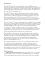
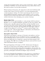
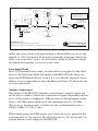
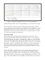
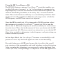
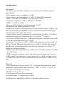
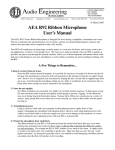
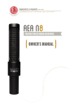
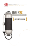
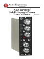
Audio Engineering
Associates
1029 N. Allen Ave.
Pasadena
CA
91104
www.ribbonmics.com
Phone: (626) 798-9128
Fax: (626) 798-2378
AEA RPQ500
High Performance Preamp
Owner’s Manual
© December 2011
Introduction
The RPQ500 module, designed after the successful RPQ preamp,
provides the same ultra-clean, high-gain signal path that has earned AEA
preamps their great reputation, in a 500 series package. The RPQ500 has
been enhanced with additional features, turning it into a workhorse tool
for your API 500 compatible rack.
The RPQ500 delivers the bandwidth and quietness needed for high
resolution recording. JFET circuit topology provides all the dynamics,
subwoofer bass, and fast transients that your microphones can record.
The input impedance of 10,000 Ω means the RPQ500 will not load
down a mic and change its sound. Low Energy Storage™ circuit design
instantly recovers from overloads for superior dynamic performance.
The CurveShaperTM offers a natural option for sculpting your sound right
at the start of the signal path. Switchable and tunable low frequency (LF)
and high frequency (HF) controls allow you to tame proximity problems
and provide HF extension and slope control. The high-frequency
CurveShaperTM excels at adding a touch of air or presence, and the
low-frequency control can remove boxiness and boominess in a fast and
unobtrusive way. The bottom line is a versatile channel strip that will
deliver an unadulterated performance in any application.
The Line/Mic switch bypasses the microphone gain stage and allows
the EQ to be used for tracking with other preamps or during mixdown.
Add the output level control and the RPQ500 becomes a high-quality
processing tool that can be used for mixing and mastering when
combined with summing racks and mixers such as the Purple Audio
Moiyn or the Roll Music Folcrom.
The original RPQ with CurveShaperTM was designed to fully capture
every nuance of ribbon microphones: vintage or modern, passive
or phantom-powered. Engineers have discovered that the RPQ also
complements their moving coil, tube and solid-state mics. By virtue of its
sonic qualities and versatility, the AEA RPQ500 is the tool of choice for
all microphones whenever a true and pristine signal path is needed.
The Front Panel
1 – Audio Signal Level indicators: The green LED snaps on at -6 dBu
to indicate the presence of signal; the red LED snaps on at +23 dBu to
warn of approaching signal overload; the yellow LED varies in bright-
1
2
3
4
5
6
7
8
9
10
11
Figure 1: AEA RPQ500 Front Panel Diagram
ness with the signal level from -3 dBu to +20 dBu.
2 – HF Gain control: This continuously variable control adjusts the HF
gain from flat (+0dB) to maximum (+20 dB); the slope of the CurveShaperTM EQ varies interactively and directly with the boost frequency
and gain settings.
3 – HF In switch: OUT is bypass; IN inserts the CurveShaperTM circuitry.
4 – HF Frequency control: This continuously variable control adjusts
the +3dB break-frequency from 2.1 kHz to 26 kHz.
5 – LF In switch: OUT is bypass; IN inserts the 20 dB low-cut shelving
filter.
6 – LF Filter Frequency ontrol: This continuously variable control
adjusts the -3dB break-frequency of the filter from 18 Hz to 360 Hz;
maximum LF reduction is -20dB.
7 – P48 switch: OUT is off; IN applies full-spec P48 Phantom Power to
the input. The red LED above the switch will indicate when P48 Phantom
Power is engaged.
8 – Mic/Line switch: OUT is mic input mode; IN bypasses the mic
preamp stage to accomodate line-level signals. The green LED above the
switch will indicate when the Line Input Mode is engaged.
9 – Polarity Invert switch: OUT is normal; IN is inverted.
10 – Input Gain rotary switch: This twelve-position switch selects from
about +7 dB to +56 dB of preamplifier gain, as measured between the
input and the unbalanced output.
11 – Output Gain control: This continuously variable control provides
up to +19 dB additional output gain in Mic Input Mode, following the
CurveShaper circuitry. It acts as a fader and allows maximum attenuation of the output signal in the full counter clockwise position. Additonal
+6 dB are applied by the balanced line driver in the output stage of the
module.
Initial Setup
The RPQ500 is a module designed for API 500 series consoles or racks.
Operation of the module in racks not compatible with the API VPR alliance specification is not recommended and will void the warranty of the
unit.
Carefully insert the module in an open slot of your 500 series console
or rack and secure it with the two flathead Phillips screws supplied with
your rack.
Do not place your rack on or in close proximity to any object that emits
strong electro-magnetic fields, such as power transformers, motors, or RF
transmitters. Similarly, do not place this unit on any surface that is hot to
the touch or where it can become overheated.
Before turning on the power, all connections to this unit should be made
and the Gain controls (ref. #10 and #11) set at their minimum (fully
counterclockwise) settings. Also before powering up this unit, be sure
that the RPQ500 module is properly seated within its rack or console,
and that the next item in the signal chain is turned down to prevent any
sudden loud noises from damaging your system or hearing.
Input Connections
The RPQ500 can be operated either as a mic preamp with the optional
EQ/filter, or as a standalone EQ/filter and fader for line level signals. The
default mode is the Microphone Input Mode with the Line/Mic switch
(ref. #8) in the OUT position. Depressing the Line/Mic switch bypasses
the first gain stage and routes the signal from the XLR input connector
straight to the optional CurveShaperTM circuitry and the Output Gain
control (ref. #11). The Line Input Mode is indicated by the illuminated
green LED above the Line/Mic switch.
Microphone Input Mode
With ribbon microphones, moving-coil dynamic microphones, and any
other microphones that do not use phantom power it is recommended
that the Phantom Power switch (ref. #7) is set to the OUT/OFF position
before and while they are connected, to prevent possible damage to the
microphones. The LED above the Phantom Power switch will be lit in red
when P48 Phantom Power is engaged.
The input impedance of the input is 10 kΩ, which means that the preamp does not load down a microphone connected to its input. This is
particularly beneficial when using ribbon microphones, because they are
sensitive to low preamp input impedances. A higher input impedance will
generally yield higher bandwidth and higher output sensitivity.
To prevent damaging the equipment in your system, it is a good idea to
test your microphone cables regularly to determine whether they have
any open, shorted, reversed, or intermittent connections.1 Defective
Input Gain
1
Input Impedance:
10 kΩ
Mic Input
1
7
10
13
17
21
26
31
36
41
45
51
56
+7 dB
Output Gain
Curve Shaper
Line Input
Input Impedance: 33 kΩ
26 kHz
+20
2
Peak
dB
Boost
9 kHz
3
- 6 dB
2.1 kHz
-64
+0 dB
Level LEDs
Red snaps on at +24 dBu
Yellow brightens from 0 to +20 dBu
Green snaps on at -6 dBu
+19
+0
High
Gain
Balanced XLR Out
(Pin 2 High)
Max Gain: +81 dB
+56
2
+6 dB
3
Phantom
On / Off
+48 V
Low Cut
18
1
2
3
Filter
85 Hz
360
RPQ500 Single Line
API 500 series preamp with P48 and CurveShaper
Minimum path, high gain and impedance, fast transient recovery JFET preamp
Audio Engineering
Associates
www.ribbonmics.com 626 - 798 - 9128
Handcrafted in Pasadena, California
Figure 2: RPQ500 Single Line diagram
cables can cause absence of signal which, as Richard Heyser once commented, is 100% distortion. Even more potentially damaging, defective
cables can cause loud “pops” or other noises, which if the level is high
can launch loudspeaker cones across the room.
Line Input Mode
The P48 Phantom Power cannot and should not be applied to line-level
devices. In Line Input Mode the inputs of the RPQ500 will always be
free from P48 Phantom Power, even if it is accidentally engaged. Nevertheless, it is recommended to keep the Phantom Power off when the unit
is used in this mode.
Output Connections
The output of the RPQ500 emulates a transformer-coupled output and
can be used as either a balanced or unbalanced signal (depending on how
your cable/system is configured). When balanced, the maximum output
level is +28 dBu; when unbalanced, the maximum level is +22 dBu.
(These are as measured into a 600Ω load; the recommended load is >
10kΩ). 0 dBu = 0.7746 V rms.)
When unbalancing the XLR output, pin-3 must be tied to ground at the
receiving end (i.e. the input of the following device). Do not tie pin-3 to
ground directly at the output of the RPQ500.
As noted above, test your cables regularly to be sure that they are in
proper working order.
Setting the Gain
Microphone Input Mode
As with any piece of audio equipment, setting and maintaining proper
signal levels are critical to obtaining optimum performance: if the level
is too low, you sacrifice noise performance; if too high, you risk overload
distortion. The AEA RPQ500 provides an easy method for setting and
monitoring the system gain.
The Input Gain control (ref. #10) provides from about +7 dB to +56 dB
of gain for the preamplifier input stage. The Output Gain control (ref.
#11) adds another +19 dB of output gain, following the CurveShaperTM
circuitry, for a total of +75 dB of gain. At any gain setting, the balanced
line driver adds another +6 dB to the final output for a total of +81 dB of
gain available.
The LED level indicators (ref. #1) monitor the signal level at a point in
the signal path just prior to the input of the balanced output driver. The
green LED comes on in the presence of low-level signal; the red LED
turns-on when you are approaching signal overload or “clipping.” The
yellow LED varies in brightness between the two to indicate the general
signal level.
Start with the Output Gain control (ref. #11) fully clockwise and the
Input Gain control (ref. #10) fully counterclockwise. Then, with the
microphone in position increase the Input Gain until the red LED turns
on when the soundsource is at its loudest. If the LED is illuminated too
often or too long, reduce the Input Gain control one step at a time until
the red LED illuminates only briefly at the loudest peaks. Once this
setting has been determined, reduce the Output Gain control to the one
o’clock position. This will provide you with a little extra headroom for
an optimum setting of the gain of the microphone preamplifier.
Note, however, that if you subsequently apply HF boost, you may need to
Figure 3: Amplitude frequency responses of mic input and filters.
reduce the Input Gain control correspondingly to avoid system overload.
Also remember, the energy and excitement generated during a performance guarantees that it will always be louder than the rehearsal, so after
determining the gain during the sound-check it is a good idea to set the
Input Gain control one or two clicks lower for the performance to allow
yet a little more margin for headroom.
Line Input Mode
When using the Line Input mode the Input Gain control (ref. #10) is
bypassed and only the Output Gain control (ref. #11) is active. For additional headroom, the signal is attenuated by 6 dB prior to the EQ/filter
section and the Output Gain control. The Output Gain control can either
apply up to +19 dB of gain in the full clockwise position or can attenuate
the signal as much as -64 dB just like a fader on a console. The output
line driver adds an additonal fixed gain of 6 dB following the Output
Gain control. The unity gain position can be found near the two o’clock
position.
Again, the LED level indicators (ref. #1) monitor the signal level at a
point in the signal path just prior to the input of the balanced output
amplifier. The green LED comes on in the presence of low-level signal;
the red LED turns-on when you are approaching signal overload or “clipping.” The yellow LED varies in brightness between the two to indicate
the general signal level.
It is suggested to start with the Output Gain control in the one o’clock
position for a setting near unity gain. Note, however, that if you subsequently apply HF boost, you may need to reduce the Output Gain control
correspondingly to avoid system overload.
Using the LF Filter
The RPQ500 was designed to complement ribbon microphones perfectly.
AEA Big RibbonTM mics deliver sub-woofer lows, which the RPQ500
renders faithfully. Such strong low frequency content can mask high
frequency intelligibility, so the tunable LF filter was engineered to reduce
low frequency energy to appropriate levels.
Directional microphones when moved closer on-axis to a sound source
become more sensitive to low frequencies. This proximity effect, otherwise known as “bass tip-up,” becomes more pronounced the closer the
distance. With some large transducer microphones such as the RCA-44
BX proximity effect begins at six feet and is extremely pronounced at a
distance of one inch.
LF filters tame proximity effect and reduce other unwanted low-frequency noise, such as air-conditioning rumble, traffic noise, “P-pops” and
breath-noise noise. However, a fixed-frequency, constant slope lowcut filter cannot handle all situations effectively. The RPQ500 offers a
flexible LF filter that can be tailored to satisfy the varying and critical
demands of both speech and music.
Pushing in the LF Filter switch (ref. #5) inserts a - 20dB (maximum)
low-cut shelving filter. The tuning control (ref. #6) adjusts the -3 dB
break-frequency of the filter. Setting the filter is easy: push in the LF
Filter switch and adjust the tuning control until you like the sound. Then
toggle the LF Filter switch quickly to compare the result against the
original.
In Line Input Mode, the LF Filter can be utilized to reduce low-frequency rumble and “muddiness” for more clarity and transparency.
Using the HF CurveShaperTM EQ
The RPQ500 features a unique CurveShaperTM circuit that enables you
to add a little extra “presence” or “air” to the pickup to compensate for
high-frequency losses that are inherent to most ribbon microphones, the
result of distant mic placement, or an overly “dry” acoustical environment. This circuit functions similarly to a conventional parametric shelving boost, but with a significant difference: the slope varies as both the
HF Frequency and HF Gain controls are adjusted.
Once the HF In switch (ref. #3) is depressed to IN/ON position, adjust
the continuously variable CurveShaperTM control (ref. #4) to tune the
filter to the +3 dB break-frequency at and above which you want to introduce the boost. Then, dial-in the amount of boost you desire with the HF
Gain control (ref. #2). The two controls are interactive, so as with the LF
filter, listen carefully to determine at what frequency and gain setting you
achieve satisfactory results.
In Line Input Mode, the CurveShaperTM becomes a versatile EQ to add
presence or air to any line level signal on a mix or even mastering.
Be careful when you add HF gain because this also affects the overall
gain structure of the preamplifier and could introduce overload distortion.
After you make this adjustment, you may need to reduce the Input Gain
control (ref. #10) correspondingly to compensate for the HF signal boost.
Specifications:
Electronic
• 81 dB of gain at 1kHz, balanced-in to balanced-out in Microphone
Input Mode
• Noise figure, rms A-weighted: < 2 dB
• Noise figure, rms unweighted: < 3 dB, 20 kHz LPF bandwidth
• EIN < -130 dBu A-weighted, 150 Ω resistive source
• Frequency response: -3dB < 1Hz and > 100 kHz
• THD: < 0.02% at 1 kHz
• Balanced Microphone Input Impedance: 10 kΩ
• Balanced Line Input Impedance: 33 kΩ
• Input Gain control: twelve-position switch provides from +7 dB to +56
dB of gain for the preamplifier circuit, as measured between the input
and the before the output line driver.
• Output Gain control: continuously variable from -64 dB to + 19 dB of
additional output gain, following the CurveShaperTM circuitry
• Switched LF Shelving filter: -3 dB break-frequency tunable from 18 Hz
to 360 Hz; maximum reduction -20 dB
• Switched CurveShaperTM EQ: +3dB break-frequency tunable from 2.1
kHz to 26 kHz; HF gain adjustable from +0 dB to +18 dB; the slope of
the HF filter varies interactively and directly with the CurveShaperTM
frequency and gain settings
• XLR output maximum level into 600Ω load: +28 dBu, balanced; 0 dBu
= 0.7746 V rms
• XLR connectors polarity: pin-1 is ground, pin-2 is high, pin-3 is low
• LED signal level indicators: green snaps on at -6 dBu, red snaps on at
+23 dBu, and yellow varies in brightness with level from -3 dBu to +20
dBu.
Physical
• Zinc-plated steel chassis with 0.125” anodized aluminum front panel
(measured without knobs and switches): 1.488” w, 6.033” d, 5.247” h
(3.78 cm x 15.32 cm x 13.32 cm)
• Weight: 14.5 oz (411 g)
• Laser engraved front panel markings
• Grayhill series 71 stepped gain switch
Specifications and details subject to change without notice.
WARRANTY
Audio Engineering Associates its microphones and preamplifiers to be
free from defects in materials and workmanship for one year. AEA offers
an additional two-year extended warranty for products registered within
60 days of purchase at no charge.
These warranties cover the original owner who has purchased equipment
from an authorized AEA dealer and are not transferrable. These warranties do not cover user damage or abuse and are void if the product has
been disassembled, repaired, or modified by anyone other than an AEA
authorized service facility. Peripheral items such as cases are not covered
under these warranties. No other warranties are expressed or implied.
For warranty service, either an existing registration must be already on
file with AEA, or an invoice from an AEA dealer showing the product serial number must accompany the equipment when it is sent to AEA.
When returning equipment for service, please download and complete a
repair form from www.ribbonmics.com. Please pack the equipment with
at least three layers of large bubble wrap and ship to:
Repair Department
Audio Engineering Associates
1029 N. Allen Ave.
Pasadena, CA 91104
AEA is committed to manufacturing quality products and reserves the
right to make improvements to its products without notice or obligation.
N.B. Disclaimer for RPQ500 modules:
The RPQ500 is a module designed for API 500 series consoles or racks.
Operation of the module in racks not compatible with the API VPR alliance specification is not recommended and will void the warranty of the
unit.
Other Products by Audio Engineering Associates:
KU4 The best unidirectional ribbon ever made - made all over again.
A440 The first active 44-style microphone. Finally, the warm sound
you love combined with the signal strength of a powered mic.
TRP High-gain 2-channel half rack unit optimized for passive ribbon microphones
RPQ Two channels of ribbon preamp with CurveShaperTM in a full
rack package
RCA Working Reproduction Microphones and replacement parts
AEA R44C Microphone - Museum Quality Reproduction
Our tribute to the classic RCA 44B using new old stock ribbon
material
AEA 44CX Microphone
6db more output for critical digital recordings
AEA 44CE Microphone
The R44CE and CXE contain the same motors as their museum-quality counterparts, but use a less expensive shell
for those who are interested in having that 44 sound, but would
rather not pay for the museum-quality trimmings.
AEA Ribbon Microphones
R84 - Studio Ribbon Mic
A840 - Active version of the award-winning R84
R88 mk2 - Stereo Ribbon Mic
R92 - Studio Ribbon Mic specifically designed for close
micing and guitar
Studio Microphone Stands and Booms
Modular Microphone Positioners and Decca Trees
Since 1983 AEA has imported and serviced the Coles 4038 studio ribbon microphone and the 4104B, “lip” mic for voice-over work in high
noise environments. We sell, service, and stock replacement parts.
In North America AEA represents CB Electronics, a leading worldwide supplier of machine control equipment to the sound-for-picture
industry. Their products specialize in professional control of and
translation between bi-phase, 9-pin serial and time code machines.
Their SR line provides low cost multiple machine remote controls
for RS-422, Sony, and Tascam DA88 protocol machines.
Audio Engineering
Associates