1
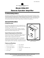
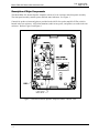
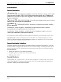
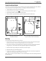
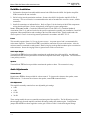
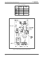
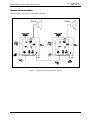
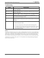
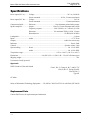
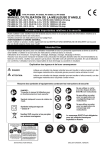
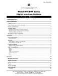
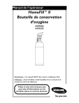
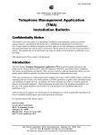
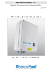
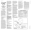
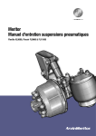
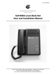
Pub.: 42004-452A GAI-TRONICS® CORPORATION A HUBBELL COMPANY Model DSA-201 Remote Speaker Amplifier TABLE OF CONTENTS Confidentiality Notice .....................................................................................................................1 General Information .......................................................................................................................1 Product Overview ................................................................................................................................... 1 System Requirements and Limitations ................................................................................................. 1 Features and Functions .......................................................................................................................... 1 Description of Major Components ........................................................................................................ 2 Installation ......................................................................................................................................3 General Information............................................................................................................................... 3 General Installation Guidelines ............................................................................................................. 3 Security Hardware.................................................................................................................................. 3 Conduit Installation Details ................................................................................................................... 4 Mounting.................................................................................................................................................. 4 Field Wire Installation............................................................................................................................ 5 Power ....................................................................................................................................................................5 Audio Input /Output..............................................................................................................................................5 Speaker .................................................................................................................................................................5 Audio Adjustments ................................................................................................................................. 5 Volume Control ....................................................................................................................................................5 Gain Adjustment ...................................................................................................................................................5 System Interconnection .......................................................................................................................... 7 Operation.........................................................................................................................................8 Power Status .........................................................................................................................................................8 Fault Status ...........................................................................................................................................................8 Maintenance....................................................................................................................................8 General Information............................................................................................................................... 8 Troubleshooting ...................................................................................................................................... 9 Service ..................................................................................................................................................................9 Specifications ................................................................................................................................10 Replacement Parts ................................................................................................................................ 10 GAI-Tronics Corporation 400 E. Wyomissing Ave. Mohnton, PA 19540 USA 610-777-1374 800-492-1212 Fax: 610-796-5954 VISIT WWW.GAI-TRONICS.COM FOR PRODUCT LITERATURE AND MANUALS Pub. 42004-452A GAI-TRONICS® CORPORATION A HUBBELL COMPANY Model DSA-201 Remote Speaker Amplifier Confidentiality Notice This manual is provided solely as an operational, installation, and maintenance guide and contains sensitive business and technical information that is confidential and proprietary to GAI-Tronics. GAI-Tronics retains all intellectual property and other rights in or to the information contained herein, and such information may only be used in connection with the operation of your GAI-Tronics product or system. This manual may not be disclosed in any form, in whole or in part, directly or indirectly, to any third party. General Information Product Overview The GAI-Tronics Digital Intercom system is designed for use in hazardous and non-hazardous area communications, both indoors and outdoors, and in high noise areas. The Model DSA-201 Remote Speaker Amplifier is designed specifically to enable audio received by a DHx Series Intercom Station to be broadcast into high noise areas. System Requirements and Limitations The DSA Series Remote Speaker Amplifier requires a 24 V ac or dc power source to operate. A DHx Intercom Station with an audio line output is required as the audio source. Audio received by the DHx Intercom Station is automatically transmitted to the remote speaker amplifier, except when the intercom station’s handset is off-hook. A maximum of six remote speaker amplifiers can be connected to a single Intercom Station. Figure 1. Model DSA-201 Remote Speaker Amplifier Features and Functions • 24 V ac or dc power • Power indicator • Enclosure rated Type 4X • Fault indicator • 12-watt speaker amplifier • Suitable for Div. 2 Hazardous Areas • Volume control • UL Listed • Gain control • CE Mark GAI-Tronics Corporation 400 E. Wyomissing Ave. Mohnton, PA 19540 USA 610-777-1374 800-492-1212 Fax: 610-796-5954 VISIT WWW.GAI-TRONICS.COM FOR PRODUCT LITERATURE AND MANUALS MODEL DSA-201 REMOTE SPEAKER AMPLIFIER Pub.: 42004-452A Page 2 of 10 Description of Major Components The Model DSA-201 Remote Speaker Amplifier consists of a rear enclosure and a front panel assembly. The front panel assembly contains power and fault status indicators. See Figure 1. Controls for speaker volume and gain are provided on the 69829-10x speaker amplifier PCBA, which is housed in the rear enclosure. All field terminations (audio in/out, power, and speaker) are made in the rear enclosure. Refer to Figure 2 and Figure 6. Figure 2. DSA Series Remote Speaker Amplifier Outline - Interior View f:\standard ioms - current release\42004 instr. manuals\42004-452a.doc 11/11 MODEL DSA-201 REMOTE SPEAKER AMPLIFIER Pub.: 42004-452A Page 3 of 10 Installation General Information CAUTION This equipment is suitable for use in Class I, Division 2, Groups A, B, C and D, Class II Division 2, Groups F, and G, Class III OR non-hazardous locations only. Combinations of equipment in your system are subject to investigation by the local Authority Having Jurisdiction at the time of installation. WARNING EXPLOSION HAZARD – Do not disconnect equipment unless power has been removed or the area is known to be non-hazardous. WARNING EXPLOSION HAZARD - Substitution of components may impair suitability for Class I, Division 2. Averttissement – Risque d’explosion - la substitition de composants peut rendre ce matériel inacceptable pour les em-placements de Classe 1, Division 2. Averttissement – Risque d’explosion – avant de déconnector l’equipment, couper le courant ou s’assurer que l’emplacement est désigné non dandereux. Install equipment without modification and according to all applicable local and national electrical codes. USA and Canada -Consult the National Electrical Code (NFPA 70), Canadian Standards Association (CSA 22.1), and local codes for specific requirements regarding your installation. Class 2 circuit wiring must be performed in accordance with NEC 725.55. General Installation Guidelines This station contains a high gain amplifier that enables operation in high noise environments. To prevent feedback problems in the system, the ambient noise levels, volume settings, and station placement must be taken into consideration. This minimum spacing requirement between stations can be reduced under the following conditions: • • • Pointing the speaker as away from Intercom Stations Placing the speaker in separate rooms from Intercom Stations Reducing volume levels Security Hardware The Model DSA-201 is vandal resistant. The front panel is attached to its enclosure with security screws. A GAI-Tronics Model 233-001 Security Screwdriver or Torx T-25 security head tip (sold separately) is required for installing or removing the front panel. f:\standard ioms - current release\42004 instr. manuals\42004-452a.doc 11/11 Pub.: 42004-452A Page 4 of 10 MODEL DSA-201 REMOTE SPEAKER AMPLIFIER Conduit Installation Details GAI-Tronics recommends installing wiring in conduit to protect against accidental damage and vandalism. To prevent moisture from entering the enclosure, we strongly recommend the following: • Conduit should enter the enclosure from the bottom. • If entered from the top, the conduit must be internally sealed to prevent moisture ingress. • Sealed fittings should be installed at all cable entry points. • Silicone sealant or equivalent should be applied around and inside all conduit entries. Figure 3. Bottom entry conduit installation details for metallic enclosures Figure 4. Top entry conduit installation details for metallic enclosures (NOT recommended) Mounting The mounting and wiring instructions are as follows: 1. Remove the four security screws from the front of the intercom station, and separate the front panel from the rear enclosure. Place the front panel and the screws in a safe location. 2. Secure the rear enclosure to the mounting surface using the four 0.28-inch mounting holes provided along with four ¼-inch diameter bolts of the appropriate length for the mounting surface. 3. Install the field wiring according to the instructions provided on page 5. 4. Adjust the audio levels as described on page 5. 5. Complete the installation by reattaching the front panel assembly to the rear enclosure using the four security screws and a toque setting of 30 in-lbs. or 35 cm-kg. NOTE: When using the GAI-Tronics Model 231-001 Pole Mounting Kit, follow the mounting instructions provided in the kit. f:\standard ioms - current release\42004 instr. manuals\42004-452a.doc 11/11 MODEL DSA-201 REMOTE SPEAKER AMPLIFIER Pub.: 42004-452A Page 5 of 10 Field Wire Installation 1. Unfasten the front panel assembly and disconnect both LEDs from the 69829-10x Speaker Amplifier PCBA located in the rear enclosure. 2. Pull all wiring into the termination enclosure. Remove the 69829-10x Speaker Amplifier PCBA if necessary. The use of ferrules is recommended on the ends of stranded wire to create a secure, reliable connection. 3. Install all connections as indicated below. Refer to Figure 5 for the location of the PCBA components wiring details and Figure 6 for the wiring details of the typical system configuration. NOTE: USA AND CANADA - Consult the National Electrical Code (NFPA 70), Canadian Standards Association (CSA 22.1), and local codes for the specific requirements regarding your installation. Install all equipment without modification and according to the local and national codes. Install conduit and seals where required. Class 2 circuit wiring must be performed in accordance with NEC 725.55. Power This assembly operates from a 24 V ac or dc power source. A separate power feed is recommended for each remote amplifier. Terminal block TB8 is provided for connection of power to the station. Also, the enclosure must be connected to earth ground. Install a ring lug on the ground conductor prior to connection to the enclosure. Secure the ring lug to the #6 ground screw on the rear enclosure. Audio Input /Output Terminal block TB6 has been provided to terminate the audio input line to this amplifier. An additional terminal block TB7 has been provided to feed the next amplifier in the chain, if applicable. The connection is not polarity sensitive. Speaker Terminal block TB5 has been provided to terminate the speaker or horn. The connection is not p Audio Adjustments Volume Control Potentiometer R38 has been provided for volume control. To increase the volume to the speaker, rotate R38 clockwise. To decrease the volume to the speaker, rotate R38 counterclockwise. Gain Adjustment This amplifier assembly contains four user adjustable gain settings: • • • • 0 dB 6 dB 12 dB 24 dB These settings enable the user to control the maximum gain of the amplifier. The 24-dB setting provides the maximum gain from the amplifier and the 0-dB setting enables the minimum gain. Configuration jumpers P9 and P6 have been supplied to set the gain. Refer to Table 1 for the desired gain settings. f:\standard ioms - current release\42004 instr. manuals\42004-452a.doc 11/11 Pub.: 42004-452A Page 6 of 10 MODEL DSA-201 REMOTE SPEAKER AMPLIFIER Table 1. Gain Settings Jumper P6 Jumper P9 0 dB 0 0 6 dB 0 1 12 dB 1 0 24 dB 1 1 Setting Figure 5. 69829-10x Remote Speaker Amplifier PCBA f:\standard ioms - current release\42004 instr. manuals\42004-452a.doc 11/11 MODEL DSA-201 REMOTE SPEAKER AMPLIFIER System Interconnection Refer to Figure 6 for a typical system wiring diagram. Figure 6. Typical system interconnection diagram f:\standard ioms - current release\42004 instr. manuals\42004-452a.doc 11/11 Pub.: 42004-452A Page 7 of 10 MODEL DSA-201 REMOTE SPEAKER AMPLIFIER Pub.: 42004-452A Page 8 of 10 Operation The Model DSA-201 Remote Speaker Amplifiers are designed to amplify audio received by the digital intercom stations. The audio is transmitted to this station via the digital intercom station’s audio line. The audio line can be routed to multiple Remote Speaker Amplifiers for broadcast into additional areas. Power Status The Power Status LED on the front panel indicates when power is applied to the unit. Fault Status The Fault Status LED on the front panel indicates when an amplifier fault (speaker line fault) has occurred. The speaker line fault must be repaired and power to this unit must be cycled in order to reset the fault indication. Maintenance General Information WARNING Always remove power to this station and any associated equipment before beginning any maintenance. 1. Inspect and replace frayed or cracked wiring. 2. Secure/replace loose wires, ferrules, and terminal lugs. 3. Remove corrosion from terminals. 4. Inspect fuses F5 and F6 of the Remote Amplifier PCBA. f:\standard ioms - current release\42004 instr. manuals\42004-452a.doc 11/11 Pub.: 42004-452A Page 9 of 10 MODEL DSA-201 REMOTE SPEAKER AMPLIFIER Troubleshooting Problem Possible Solution Low speaker volume Increase the volume settings via potentiometer R38 and/or increase the gain setting via P9 and P6. High speaker volume Decrease the volume settings via potentiometer R38 and/or decrease the gain setting via P9 and P6. No speaker output Increase the volume settings via potentiometer R38. Verify power is applied to the unit at TB8. Verify audio is present at the audio input TB6. No power indication Verify power is applied to the unit at TB8. Check fuses F5 and F6. Replace fuses with identical rating/type if faulty. Fault Indication An amplifier fault is an indication that a speaker line fault has occurred. Repair the speaker line fault and cycle power (off/on) in order to reset the fault indication. Feedback 1. Point the speakers away from the interfering station. 2. Reduce the speaker volume. 3. Increase the distance between the speaker and the interfering station. 4. Two digital intercom stations can be barred from communication. Refer to the “Protection against Feedback Configuration” section of the Central Switch manual for details. Service If your Intercom Station requires service, contact your Regional Service Center for a return authorization number (RA#). Equipment should be shipped prepaid to GAI-Tronics with a return authorization number and a purchase order number. If the equipment is under warranty, repairs will be made without charge. Please include a written explanation of all defects to assist our technicians in their troubleshooting efforts. Call 800-492-1212 inside the USA or 610-777-1374 outside the USA for help identifying the Regional Service Center closest to you. f:\standard ioms - current release\42004 instr. manuals\42004-452a.doc 11/11 MODEL DSA-201 REMOTE SPEAKER AMPLIFIER Pub.: 42004-452A Page 10 of 10 Specifications Power input (24 V ac) ......... Voltage ................................................................................ 24 V ac, 50/60 Hz Power consumed ................................................ 44 VA, 36 watts (maximum) Power input (24 V dc)......... Voltage ................................................................................................. 24 V dc Power consumed ............................................................. 35 watts (maximum) Construction finish.............. Enclosure............................................... Cast aluminum painted safety orange Speaker amplifier ................ Output............................................... Class D, 12 watts minimum into 8 ohms Frequency response ............................. 200–7,000 Hz, +0/−3 dB ref. @ 1 kHz Distortion............................................ 2% maximum THD @ 1 kHz, 12 watts Hum and noise........................................................... −55 dB (20 Hz–20 kHz) Loudspeaker........................................................................................................................................ 8 ohms Inputs ................................. Audio............................................................................................. 0.775 Vrms Outputs ..................................................................................................................... Audio line to next amp Indicators ................................................................................................................................... Power, Fault Controls ...................................................................................................................... Speaker volume, Gain System cabling.................... Power..................................................................................... No. 12–18 AWG Audio..................................................................................... No. 16–24 AWG Temperature range ............................................................................... −4 ºF to + 140 ºF (−20 ºC to +60 ºC) Dimensions ........................................................ 8.0 (203.2) W × 9.5 (241.3) H × 3.9 (99.0) D inches (mm) Shipping weight .................................................................................................................................... 7 lbs. Unit must be locally powered. Approvals NRTL Listed for USA and Canada Class I, Div. 2, Groups A, B, C, and D, T3C Class II, Div. 2, Groups F and G Class III, Div. 2 Type 4X CE Mark Safety of Information Technology Equipment ...... UL 60950, CAN/CSA-C22.2 No. 60950-00, IEC 60950 Replacement Parts Contact GAI-Tronics for replacement part information. f:\standard ioms - current release\42004 instr. manuals\42004-452a.doc 11/11 Warranty Equipment. GAI-Tronics warrants for a period of one (1) year from the date of shipment, that any GAI-Tronics equipment supplied hereunder shall be free of defects in material and workmanship, shall comply with the then-current product specifications and product literature, and if applicable, shall be fit for the purpose specified in the agreed-upon quotation or proposal document. If (a) Seller’s goods prove to be defective in workmanship and/or material under normal and proper usage, or unfit for the purpose specified and agreed upon, and (b) Buyer’s claim is made within the warranty period set forth above, Buyer may return such goods to GAI-Tronics’ nearest depot repair facility, freight prepaid, at which time they will be repaired or replaced, at Seller’s option, without charge to Buyer. Repair or replacement shall be Buyer’s sole and exclusive remedy. The warranty period on any repaired or replacement equipment shall be the greater of the ninety (90) day repair warranty or one (1) year from the date the original equipment was shipped. In no event shall GAI-Tronics warranty obligations with respect to equipment exceed 100% of the total cost of the equipment supplied hereunder. Buyer may also be entitled to the manufacturer’s warranty on any third-party goods supplied by GAI-Tronics hereunder. The applicability of any such third-party warranty will be determined by GAI-Tronics. Services. Any services GAI-Tronics provides hereunder, whether directly or through subcontractors, shall be performed in accordance with the standard of care with which such services are normally provided in the industry. If the services fail to meet the applicable industry standard, GAI-Tronics will re-perform such services at no cost to buyer to correct said deficiency to Company's satisfaction provided any and all issues are identified prior to the demobilization of the Contractor’s personnel from the work site. Re-performance of services shall be Buyer’s sole and exclusive remedy, and in no event shall GAITronics warranty obligations with respect to services exceed 100% of the total cost of the services provided hereunder. Warranty Periods. Every claim by Buyer alleging a defect in the goods and/or services provided hereunder shall be deemed waived unless such claim is made in writing within the applicable warranty periods as set forth above. Provided, however, that if the defect complained of is latent and not discoverable within the above warranty periods, every claim arising on account of such latent defect shall be deemed waived unless it is made in writing within a reasonable time after such latent defect is or should have been discovered by Buyer. Limitations / Exclusions. The warranties herein shall not apply to, and GAI-Tronics shall not be responsible for, any damage to the goods or failure of the services supplied hereunder, to the extent caused by Buyer’s neglect, failure to follow operational and maintenance procedures provided with the equipment, or the use of technicians not specifically authorized by GAI-Tronics to maintain or service the equipment. THE WARRANTIES AND REMEDIES CONTAINED HEREIN ARE IN LIEU OF AND EXCLUDE ALL OTHER WARRANTIES AND REMEDIES, WHETHER EXPRESS OR IMPLIED BY OPERATION OF LAW OR OTHERWISE, INCLUDING ANY WARRANTIES OF MERCHANTABILITY OR FITNESS FOR A PARTICULAR PURPOSE. Return Policy If the equipment requires service, contact your Regional Service Center for a return authorization number (RA#). Equipment should be shipped prepaid to GAI-Tronics with a return authorization number and a purchase order number. If the equipment is under warranty, repairs or a replacement will be made in accordance with the warranty policy set forth above. Please include a written explanation of all defects to assist our technicians in their troubleshooting efforts. Call 800-492-1212 (inside the USA) or 610-777-1374 (outside the USA) for help identifying the Regional Service Center closest to you. (Rev. 10/06)