1
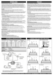
KVA-S300
AUDIO VIDEO SELECTOR
INSTRUCTION MANUAL
SELECTEUR AUDIO VIDEO
MODE D’EMPLOI
AUDIO-VIDEO-WÄHLER
BEDIENUNGSANLEITUNG
AUDIO-VIDEO-KIEZER
GEBRUIKSAANWIJZING
SELETTORE AUDIO VIDEO
ISTRUZIONI PER L’USO
SELECTOR DE AUDIO VÍDEO
MANUAL DE INSTRUCCIONES
SELECTOR AUDIO VÍDEO
MANUAL DE INSTRUÇÕES
©B64-2020-00 (W) (DT)
Installation
Safety precautions
2WARNING
To prevent injury or fire, take the following precautions:
• Insert the unit all the way in until it is fully locked in place. Otherwise it may fall out of place when
jolted.
• When extending the ignition, battery, or ground wires, make sure to use automotive-grade wires or
other wires with a 0.75mm2 (AWG18) or more to prevent wire deterioration and damage to the wire
coating.
• If the unit starts to emit smoke or strange smells, turn off the power immediately and consult your
Kenwood dealer.
2CAUTION
To prevent damage to the machine, take the following precautions:
• Make sure to ground the unit to a negative 12V DC power supply.
• Do not open the top or bottom covers of the unit.
Accessories
Part name
q
w
External view
......... Number of items
Remote controller
(cable length:5m)
Installation
bracket
.........1
t (Loop : 25x70mm)
.........2
Double-side
.........2
y adhesive tape
.........2
Tapping screw
.........2
Velcro strips
r (Hook : 12x65mm)
External view
......... Number of items
Velcro strips
Velcro strips
e (20x60mm)
Part name
u (ø3x6mm)
.........4
Tapping screw
.........2
i (ø4x12mm)
.........4
2CAUTION
The use of any accessories except for those provided might result in damage to the unit. Make sure
only to use the accessories shipped with the unit, as shown above.
Installation procedure
1. Remove the ignition key and disconnect the negative - terminal of the battery to prevent short
circuits.
2. Set the unit according to the intended usage.
3. Connect the input and output cables of the units.
4. Connect the Ignition wire and grounding wire following this order.
5. Install the unit in the car.
6. Connect the negative - terminal of the battery.
2CAUTION
• Be sure to turn the power off before changing the setting of any switch.
• If the fuse blows, check cables for shorts, then replace the fuse with one of the same rating.
• Check that no unconnected wires or connectors are touching the car body.
• After installation, check that the brake lamps, winkers, and wipers work properly.
2-English
Connecting Cables to Terminals (example)
Remote control terminal 1
(Front side)
REVERSE VIDEO
OFF
AUTO
REMOTE
3
Remote
controller
REMOTE
1
REMOTE
2
Remote control
terminal 3
Power indicator
Remote control
terminal 2
NOTE
When connecting the remote control connector, note
that the arrow marking on the connector is upper side.
Headphone terminal
Reverse Lamp
Video & audio-in Video & audio-in
terminals 3
terminals 2
Video & audio-in
Reverse switch terminals 1
(Right side)
VIDEO
AV INPUT 1
L
R
VIDEO
AV INPUT 2
L
R
VIDEO
AV INPUT 3
L
R
RCA cable
(Commercially available part)
Reverse detection wire (Pink)
Video input (Yellow)
Audio left input (White)
Audio right input (Red)
Ignition wire
(Red)
Rear-view camera etc.
Fuse
VCR,GAME Player,DVD Player etc.
+
Ground wire
(Black)
–
(AV out)
Battery
Video & audio-out
terminals 3
KVC-1000 ,VZ807P/N ,LZ-800W,
TV Tuner etc.
Video & audio-out
terminals 2
AV OUTPUT 3
L
VIDEO
(Left side)
RCA cable
(Commercially available part)
Video output (Yellow)
Audio left output (White)
Audio right output (Red)
R
Video & audio-out
terminals 1
AV OUTPUT 2
L
VIDEO
R
AV OUTPUT 1
L
VIDEO
R
NOTE
Reconnecting the output signal
from the AV OUTPUT1 to the TV
TUNER input when connecting
the TV TUNER to the AV
INPUT1 allows you to display the
video of AV INPUT2 and AV
INPUT3 on the monitor
connected to the TV TUNER.
(AV in)
Monitor (AV in) etc.
Monitor (AV in) etc.
English-3
Installation
Installation
■ Securing to audio board
Tapping screw
(ø4X12mm)
(Accessoryi)
1 Attach the installation brackets to the
bottom of the KVA-S300 using the binding
screws (ø3 x 6mm).
2 Mount the KVA-S300 to an audio board using
the self-tapping screws (ø4 x 12mm).
Installation board,etc.
(thickness:15mm or more)
Installation
brackets
(Accessoryw)
Tapping screw
(ø3X6mm)
(Accessoryu)
■ Securing to the body of the vehicle
Peel off the protection paper from the Velcro strip
(Accessory 3) and paste the one side to the
bottom of the KVA-S300 and the other side to the
body of the vehicle.
2CAUTION
Please do not install the unit near the
dashboard, the rear tray, or other important
components. Doing so could lead to injury or
accident should the unit come off due to a
shock and strike a person or an important
component.
Tapping screws should be used for mounting.
(Attachment with velcro strips, although easy,
can come off with a shock.)
Velcro strips
(Accessorye)
Attaching the remote controller
1 Clean the place where you want to attach
the remote controllor with a detergent to
remove dirt or oil and wipe the surface with
a soft dry cloth.
Velcro strips
(Hook:Accessory4 )
2 Attach the remote controller to the center
console or any convenient place using the
supplied Velcro strips.
NOTE
If you find that the Velcro strips (Loop:
Accessory5) will not attach to the center
console surface, provide the double-sided
adhesive tape (Accessory6) to the Velcro for
secure attachment. (Paste the yellow
protection paper side to the Velcro strip and
the transparent protection paper side to the
body of the vehicle.)
4-English
Velcro strips
(Loop:Accessory5 )
Operation
Operation of remote controller
■ Volume adjustment
Turning clockwise the headphone volume knob on the
remote controller increases the sound volume from the
headphone and turning counterclockwise decreases the
volume.
Headphone
volume knob
NOTE
Headphone volume, if minimized, will not be muted.
■ AV-in source switching
AV-in source
switch control
If the remote control unit is connected to the remote
connection terminal 1, you can select the inputs from AV
INPUTs 1, 2 and 3 for the video available from AV
OUTPUT1.
Setting the remote control AV-in source control to 1
switches to the AV INPUT1 video, and 2 to the AV
INPUT2 and 3 to the AV INPUT3.The same is true with
the remote connection terminals 2 and 3.
NOTE
The outputs where no corresponding remote control
units are connected are fed with the video images from
the AV INPUT1.
Headphone
(Commercially available part)
REVERSE VIDEO AUTO/OFF switching
Setting the REVERSE VIDEO AUTO/OFF selector switch
to AUTO with the rear-view camera (Commercially
available part) connected to the AV INPUT3 allows you to
automatically switch the AV OUTPUT1 video alone to the
rear-view camera when you put your car into reverse
gear.
REVERSE VIDEO
OFF
AUTO
REMOTE
3
REMOTE
2
NOTE
If the KVA-S300 is not connected with the rear-view
camera, note that the REVERSE VIDEO AUTO/OFF
selector switch be turned off..
REVERSE VIDEO AUTO/OFF
selector switch
Specifications
Specifications subject to change without notice.
Switching Unit
Weight ......................................................814 g
Size....................168(W) x 180.4(H) x 30(D) mm
Video input level (RCA jack)
..............................................1 Vp-p/75 Ω
Audio input level (RCA jack)
....................................1.15 Vrms (22 KΩ)
Video output level (RCA jack)
..............................................1 Vp-p/75 Ω
Audio output level (RCA jack)
......................................1.15 Vrms (1 KΩ)
Controllor Unit
Size......................40(W) x 105(H) x 20.5(D) mm
Weight ......................................................160 g
Phone jack (Miniplug x 1) Audio output level
..........................15 mW + 15 mW (32 Ω)
General
Operating voltage ........14.4 V DC (10.5 to 16 V)
Current Consumption ............................≤300 mA
Input level (Reverse detection wire)
..............................................2.5 to 16 V
English-5
Installation
Précautions de sécurité
2AVERTISSEMENT
Pour éviter toute blessure et/ou incendie, veuillez prendre les précautions suivantes:
• Insérez l’appareil à fond jusqu’à ce qu’il soit complètement calé. Sinon, il risquerait d’être projeté en cas
de collisions ou de cahots.
• Si vous prolongez un câble d’alimentation, de batterie ou de masse, assurez vous d’utiliser un câble
pour automobile ou un câble avec une section de 0,75mm2 (AWG18) afin d’éviter tous risques de
détérioration ou d’endommagement du revêtement des câbles.
• Si l’appareil commence à émettre de la fumée ou une odeur bizarre, mettez immédiatement l’appareil
hors tension et consultez un revendeur Kenwood.
2ATTENTION
Pour éviter tout dommage à l'appareil, veuillez prendre les précautions suivantes:
• Assurez-vous de mettre l'appareil à la masse sur une alimentation négative de 12V CC.
• N'ouvrez pas le couvercle supérieur ou inférieur de l'appareil.
Accessoires
Nom de la piéce
Vue externe
......... Nombre d’éléments
Télécommande
w
Attaches
d’installation
t (Boucle :
.........1
.........2
y double face
.........2
Vis taraudeuse
.........2
Bandes velcro
r (Crochet :
12x65mm)
25x70mm)
Ruban adhésif
.........2
Bandes velcro
e (20x60mm)
Vue externe
......... Nombre d’éléments
Bandes velcro
q (longueur du
câble : 5 m)
Nom de la piéce
u (ø3x6mm)
.........4
Vis taraudeuse
.........2
i (ø4x12mm)
.........4
2ATTENTION
L’utilisation d’accessoires autres que les accessoires fournis pourrait endommager l’appareil.
Assurez-vous d’utiliser les accessoires fournis, indiqués ci-dessus.
Procédure d'installation
1. Retirer la clé de contact et débrancher la borne négative - de la batterie pour éviter les court-circuits.
2. Régler l'appareil en fonction de l'utilisation désirée.
3. Raccorder les câbles d’entrée et de sortie de l’appareil.
4. Relier, dans l'ordre, le câble d’allumage et le câble de masse.
5. Monter l’appareil dans la voiture.
6. Raccorder la borne négative - de la batterie.
2ATTENTION
• Veiller à mettre l'appareil hors tension avant de changer la position des commutateurs.
• Si le fusible saute, vérifier si les câbles ne sont pas court-circuités, et remplacer le fusible par un autre
fusible de même capacité nominale.
• Vérifier qu’aucun câble ou connecteur non raccordé ne touche la carrosserie de la voiture.
• Après l’installation, vérifier que les voyants de frein, les clignotants et les essuie-glace fonctionnent
correctement.
6-Français
Connexion des câbles sur les prises (exemple)
Borne de télécommande 1
(Avant)
REVERSE VIDEO
OFF
AUTO
REMOTE
3
REMOTE
2
Télécommande
REMOTE
1
Borne de
télécommande 3
Borne de
télécommande 2
Indicateur Power
REMARQUE
Lorsque vous branchez le connecteur de
télécommande, veuillez remarquer que la flèche
indiquée sur le connecteur est sur le côté supérieur.
Feu de recul
Interrupteur de
marche arrière
Borne de casque
Bornes d'entrée Bornes d'entrée
vidéo & audio 2 vidéo & audio 3
Bornes d'entrée
vidéo & audio 1
(Côté droit)
VIDEO
AV INPUT 1
L
R
VIDEO
AV INPUT 2
L
R
VIDEO
AV INPUT 3
L
R
Câble RCA (Pièces disponibles
dans le commerce)
Fil de détection de
marche arrière (Rose)
Entrée vidéo (Jaune)
Entrée audio gauche (Blanc)
Entrée audio droite (Rouge)
Câble d’allumage
(Rouge)
Caméra de rétrovision etc.
Fusible
VCR,Console de GAME,
Lecteur DVD etc.
+
Câble de
masse (Noir)
–
(Sortie AV)
Batterie
Bornes de sortie
vidéo & audio 3
KVC-1000,VZ807P/N,LZ-800W,
Tuner TV etc.
Bornes de sortie
vidéo & audio 2
AV OUTPUT 3
L
VIDEO
(Côté gauche)
Câble RCA (Pièces disponibles
dans le commerce)
Sortie vidéo (Rouge)
Sortie audio gauche (Blanc)
Sortie audio droite (Jaune)
R
Bornes de sortie
vidéo & audio 1
AV OUTPUT 2
L
VIDEO
R
AV OUTPUT 1
L
VIDEO
R
REMARQUE
La reconnexion du signal de
sortie depuis la sortie AV
OUTPUT1 vers l’entrée du TV
TUNER tout en connectant le
TV TUNER à l’entrée AV INPUT1
vous permet d’afficher la vidéo
de AV INPUT2 et de AV INPUT3
sur le moniteur connecté au TV
TUNER.
(Entrée AV)
Moniteur (Entrée AV) etc.
Moniteur (Entrée AV) etc.
Français-7
Installation
Installation
■ Fixation sur le panneau audio
Vis taraudeuses
(ø4X12mm)
(Accessoirei)
1 Fixez les attaches d'installation sur la face
inférieure du KVA-S300 en utilisant les vis de
fixation (ø3 x 6mm).
2 Installez le KVA-S300 sur une plaque audio
en utilisant les vis auto-taraudeuses (ø4 x
12mm).
Tableau d'installation,etc.
(épaisseur:15mm ou plus)
Attaches
d’installation
(Accessoirew)
Vis taraudeuses
(ø3X6mm)
(Accessoireu)
■ Fixation sur la carrosserie du véhicule
Retirez le papier de protection de la bande Velcro
(Accessoire 3) et collez ce côté sur le dessous du
KVA-S300 et l’autre sur la carrosserie du véhicule.
2ATTENTION
Prière de ne pas installer près du tableau de
bord, de la plage arrière ou d’éléments
importants. Cela pourrait occasionner une
blessure ou un accident si l’appareil devait se
détacher à cause d’un choc, et heurter une
personne ou un élément important.
Des vis taraudeuses doivent être utilisées pour
le montage. (Une fixation à l’aide d’une bande
velcro est facile, mais peut se détacher lors
d’un choc.)
Bandes velcro
(Accessoiree)
Fixation de la télécommande
1 Nettoyez l'emplacement où vous souhaitez
fixer la télécommande avec un détergent pour
retirer toute trace de poussière ou d'huile et
essuyez-le avec un chiffon doux sec.
Bandes Velcro
(Crochet:Accessoire4 )
2 Fixez la télécommande au centre de la
console ou à tout emplacement pratique en
utilisant le ruban adhésif à double face fourni.
REMARQUE
If you find that the Velcro strips (Loop:
Accessory5) will not attach to the center
console surface, provide the double-sided
adhesive tape (Accessory6) to the Velcro for
secure attachment.(Collez le côté avec le
ruban de protection jaune sur la bande Velcro
et le celui avec le ruban de protection
transparent sur la carrosserie du véhicule.)
8-Français
Bandes Velcro
(Boucle:Accessoire5 )
Opération
Fonctionnement de la télécommande
■ Réglage du volume
Tournez le bouton de volume de la télécommande dans
le sens horaire pour augmenter le volume du son et dans
le sens anti-horaire pour le diminuer.
Bouton de volume
de casque
REMARQUE
Le casque ne sera pas mis en sourdine, même si son
volume a été minimisé.
■ Commutation de source d'entrée AV
Lorsque l’unité de télécommande est connectée à la
borne de télécommande 1, il vous est possible de
sélectionner les entrées de AV INPUT 1, 2 et 3 pour la
vidéo disponible depuis AV OUTPUT1.
Le réglage du sélecteur de source d'entrée AV (AV-IN) de
la télécommande sur 1 commute l'appareil sur l'entrée
vidéo AV1, sur 2 avec l'entrée vidéo AV2 et sur 3 avec
l'entrée vidéo AV3.La même chose est valide pour les
bornes de connexion de télécommande 2 et 3.
Commande de
l'interrupteur
de source
d'entrée AV
REMARQUE
Casque
(Pièces disponibles dans le commerce)
La même chose est valide pour les bornes de
connexion de télécommande 2 et 3.
Commutation Auto/Arrêt du sélecteur rétro vision REVERSE VIDEO AUTO/OFF
Réglage du sélecteur REVERSE VIDEO AUTO/OFF sur
AUTO avec une caméra de rétro vision (disponible dans
la commerce) connectée à l’entrée AV INPUT3 vous
permet de commuter automatiquement la sortie vidéo AV
OUTPUT1 uniquement sur la caméra de rétro vision dès
que vous mettez le véhicule en marche arrière.
REVERSE VIDEO
OFF
AUTO
REMOTE
3
REMOTE
2
REMARQUE
Si le KVA-S300 n’est pas connecté à une caméra de
rétro vision, veillez noter que le sélecteur REVERSE
VIDEO AUTO/OFF doit être placé sur arrêt (OFF).
Sélecteur de REVERSE VIDEO
AUTO/OFF
Spécifications
Les spécifications sont sujettes à changements sans notification.
Unité de commutation
Poids ..................................................................814 g
Taille ..............................168(L) x 180.4(H) x 30(P) mm
Niveau d’entrée vidéo (fiches RCA)
......................................................1 Vp-p/75 Ω
Niveau d’entrée audio (fiches RCA)
............................................1.15 Vrms (22 KΩ)
Niveau de sortie vidéo (fiches RCA)
......................................................1 Vp-p/75 Ω
Niveau de sortie audio (fiches RCA)
..............................................1.15 Vrms (1 KΩ)
Unité de contrôleur
Taille ................................40(L) x 105(H) x 20.5(P) mm
Poids ..................................................................160 g
Niveau de sortie audio de la prise de casque
(Mini jack x 1)
....................................15 mW + 15 mW (32 Ω)
Généralités
Tension d'utilisation ..............14.4 V DC (10.5 to 16 V)
Consommation de courant ..............................≤300 mA
Niveau d'entrée (fil de détection de marche arrière)
........................................................2.5 to 16 V
Français-9
Einbau
Sicherheitshinweise
2WARNUNG
Zur Vermeidung von Bränden und Verletzungen beachten Sie bitte die folgenden Hinweise:
• Befestigen Sie das Gerät sicher im Einbauschacht, damit es bei einem Unfall nicht durch das Wageninnere
geschleudert wird..
• Verwenden Sie bei Verlegung des Betriebsstrom-, Speicherschutz- und Massekabels besonders
strapazierfähige und speziell für die Installation im Auto angebotene Kabel mit einem Leitungsquerschnitt
von mindestens 0,75 mm2 (AWG 18).
• Schalten Sie das Gerät bei Geruch- oder Rauchentwicklung sofort aus und suchen Sie einen KENWOODFachhändler auf.
2ACHTUNG
Bitte beachten Sie folgende Vorsichtsmaßnahmen, damit Ihr Gerät stets einwandfrei funktioniert:
• Betreiben Sie das Gerät ausschließlich mit 12-Volt-Gleichstrom und negativer Masseverbindung.
• Entfernen Sie nicht die oberen oder unteren Gehäuseabdeckungen.
Zubehör
Teilebezeichnung
q
w
Ansicht
......... Anzahl der Teile
Fernbedienung
(Kabellänge: 5m)
Installationshalter
ungen
Velcrostreifen
.........1
25x70mm)
.........2
Doppelseitiges
.........2
y Klebeband
.........2
Blechschraube
.........2
Velcrostreifen
r (Haken :
12x65mm)
Ansicht
......... Anzahl der Teile
t (Schlaufe :
Velcrostreifen
e (20x60mm)
Teilebezeichnung
u (ø3x6mm)
.........4
Blechschraube
.........2
i (ø4x12mm)
.........4
2ACHTUNG
Verwenden Sie nur dieses Original-Zubehör, um Beschädigungen Ihres Autoradios zu vermeiden.
Verwenden Sie nur das mit dem Gerät gelieferte, oben aufgeführte Zubehör.
Hinweise zum Einbau
1. Ziehen Sie den Zündschlüssel ab und trennen Sie den Minuspol von der Battrie, um einen
Kurzschluß zu vermeiden.
2. Das Gerät entsprechend der vorgesehenen Verwendung einstellen.
3. Verbinden Sie die Ein-und Ausgangskabel der einzelnen Geräte.
4. Das Spannungsversorgungskabel und das Massekabel in dieser Reihenfolge anschließen.
5. Bauen Sie die Geräte ein.
6. Schließen Sie den Minuspol Batterie an.
2ACHTUNG
• Bevor eine Schalterstellung verändert wird, muß unbedingt die Stromversorgung ausgeschaltet werden.
• Wenn die Sicherung anspricht, überprüfen Sie die Kabel nach Kurzschlüssen. Ersetzen Sie die defekte
Sicherung durch eine intakte Sicherung gleichen Werts.
• Achten Sie darauf, daß keine nicht angeschlossenen Kabelenden mit der Karrosserie des Fahrzeugs in
Verbindung kommen können.
• Prüfen Sie nach dem Einbau, ob Bremslichter, Blinker und Scheibenwischer einwandfrei funktionieren.
10-Deutsch
Anschlußdiagramm (beispiel)
(Vorderseite)
REMOTE
3
REVERSE VIDEO
OFF
AUTO
REMOTE
2
Fernbedienungs-Buchse 1
Fernbedienung
REMOTE
1
FernbedienungsBuchse 3
POWER-Anzeige
FernbedienungsBuchse 2
ANMERKUNG
Wenn Sie den Anschluss der Fernbedienung vornehmen,
vergewissern Sie sich, dass die Pfeilmarkierung am Anschluss
nach oben zeigt.
(Rechte Seite)
Kopfhörer-Buchse
Video & AudioVideo & AudioEingangsbuchsen 2 Eingangsbuchsen 3
Video & AudioRücklicht
Umkehrschalter Eingangsbuchsen 1
VIDEO
AV INPUT 1
L
R
VIDEO
AV INPUT 2
L
R
VIDEO
AV INPUT 3
L
R
RCA-Kabel
(Im Fachhandel erhältliches Teil)
RückwärtsErkennungsdraht (Rosa)
Video-Eingang (Gelb)
linker Audio-Ausgang (Weiß)
Rechter Audio-Eingang (Rot)
Spannungs
versorgungs
kabel (Rot)
Rückwärtige Kamera usw.
Sicherung
VCR,GAME-Player,DVD-Player etc.
+
Massekabel
(Schwarz)
–
(AV aus)
Batterie
Video & AudioAusgangsbuchsen 3
KVC-1000,VZ807P/N,LZ-800W,
TV-Tuner usw.
Video & AudioAusgangsbuchsen 2
AV OUTPUT 3
L
VIDEO
(Linke Seite)
R
Video & AudioAusgangsbuchsen 1
AV OUTPUT 2
L
VIDEO
R
AV OUTPUT 1
L
VIDEO
R
ANMERKUNG
Wenn Sie den Wiederanschluss
des Ausgangssignals vom AV
OUTPUT1 zum TV TUNEREingang vornehmen, während
TV TUNER an AV INPUT1
angeschlossen ist, ermöglicht
Ihnen dies die Anzeige des
Videos von AV INPUT2 und AV
INPUT3 auf dem Monitor, der an
TV TUNER angeschlossen ist.
RCA-Kabel
(Im Fachhandel erhältliches Teil)
(AV ein)
Video-Ausgang (Gelb)
linker Audio-Ausgang (Weiß)
Rechter Audio-Ausgang (Rot)
Monitor (AV ein) usw.
Monitor (AV ein) usw.
Deutsch-11
Einbau
Einbau
■ An der Audiotafel sichern
Schneidschraube
(ø4X12mm)
(Zubehöri)
1 Befestigen Sie die Installationsklammern mit
Hilfe der Klemmschrauben (ø3 x 6 mm) auf
der Unterseite des KVA-S300.
2 Befestigen Sie den KVA-S300 mit Hilfe der
Gewindeschrauben (ø4 x 12 mm) auf einer
Audioplatine.
Einbauplatte usw.
(Stärke:15mm oder mehr)
Installationshalt
erungen
(Zubehörw)
Schneidschraube
(ø3X6mm)
(Zubehöru)
■ Sichern der Fahrzeug-Karosserie
Lösen Sie das Schutzpapier vom Klebeband (Zubehör 3)
und kleben Sie die eine Seite auf die Unterseite des KVAS300 und die andere Seite auf die Karosserie des Fahrzeugs.
2ACHTUNG
Die Installation nicht in der Nähe des Armaturenbretts,
der hinteren Ablage oder von wichtigen Komponenten
durchführen. Anderenfalls kann es zu Verletzungen oder
einem Unfall kommen, sollte sich die Einheit aufgrund
einer Erschütterung lösen und eine Person oder eine
wichtige Komponente treffen.
Verwenden Sie für die Installation Schneidschrauben.
(Die Befestigung mit Velcrostreifen ist sehr einfach, kann
sich jedoch aufgrund einer Erschütterung leicht lösen.)
Velcrostreifen
Velcrostreifen
(Zubehöre)
Anbringen der Fernbedienung
1 Reinigen Sie die Fläche, auf der Sie die Fernbedienung
anbringen möchten, mit einem Reinigungsmittel,
damit eventuell vorhandene Verschmutzungen oder Öl
entfernt werden, und wischen Sie die Fläche danach
mit einem weichen trockenen Tuch ab.
Velcrostreifen
(Haken:Zubehör4 )
2 Bringen Sie die Fernbedienung an der mittleren
Konsole oder an einer anderen geeigneten Stelle mit
Hilfe des mitgelieferten beidseitigem Klebebandes an.
ANMERKUNG
Wenn Sie feststellen, dass das Klebeband (Schlaufe:
Zubehör 5) sich nicht an der Oberfläche der mittleren
Konsole befestigen lässt, verwenden Sie zusätzlich
das doppelseitige Klebeband (Zubehör 6) für eine
sichere Befestigung.(Kleben Sie die gelbe Seite des
Schutzpapiers auf das Klebeband und die transparente
Seite des Schutzpapiers auf die Karosserie des
Fahrzeugs.)
12-Deutsch
Velcrostreifen
(Schlaufe:Zubehör5 )
Betrieb
Betrieb der Fernbedienung
■ Einstellung der Lautstärke
Wenn der Lautstärkeregler für die Kopfhörer auf der
Fernbedienung im Uhrzeigersinn gedreht wird, erhöht
sich die Lautstärke an den Kopfhörern; das Drehen gegen
den Uhrzeigersinn verringert die Lautstärke.
ANMERKUNG
KopfhörerLautstärkeregler
Die Kopfhörer-Lautstärke, kann – wenn auf minimale
Lautstärke geschaltet – nicht stumm geschaltet werden.
■ AV-Eingangs-Quellenschaltung
Wenn das Fernbedienungsgerät an den
Fernbedienungsanschluss 1 angeschlossen ist, können
Sie den Eingang von AV INPUT 1, 2 und 3 für Video, das
an AV OUTPUT1 verfügbar ist, auswählen.
Wenn die Fernbedienungs-AV-Eingangs-Quellensteuerung
auf 1 gestellt ist, wird zu AV INPUT1-Video umgeschaltet;
wenn die Steuerung auf 2 steht, wird zu AV INPUT2 und
auf 3 zu AV INPUT3 umgeschaltet.Dasselbe gilt für die
Fernbedienungsanschlüsse 2 und 3.
AVEingangsquellenSchaltersteuerung
ANMERKUNG
Die Ausgänge, an die keine passenden
Fernbedienungsgeräte angeschlossen sind, werden mit
den Videobildern von AV INPUT1 gespeist.
Kopfhörer
(Im Fachhandel erhältliches Teil)
REVERSE VIDEO AUTO/OFF-Schaltung
Wenn der Auswahlschalter REVERSE VIDEO AUTO/OFF
auf AUTO gestellt wird, während die rückwärtige Kamera
(im Handel erhältlich) an AV INPUT3 angeschlossen ist,
ermöglicht Ihnen dies, AV OUTPUT1 Video automatisch
einzig auf die rückwärtige Kamera einzustellen, wenn Sie
den Rückwärtsgang Ihres Fahrzeuges einlegen.
REVERSE VIDEO
OFF
AUTO
REMOTE
3
REMOTE
2
ANMERKUNG
Wenn der KVA-S300 nicht an die rückwärtige Kamera
angeschlossen ist, nehmen Sie bitte zur Kenntnis, dass
der Auswahlschalter REVERSE VIDEO AUTO/OFF
ausgeschaltet sein sollte.
REVERSE VIDEO AUTO/OFFAuswahlschalter
Technische Daten
Die technischen Daten können sich ohne besonderen Hinweis ändern.
Schaltungseinheit
Gewicht ..............................................................814 g
Abmessungen ................168(B) x 180.4(H) x 30(T) mm
Videoeingangspegel (RCA-Buchsen)
......................................................1 Vp-p/75 Ω
Audioeingangspegel (RCA-Buchsen)
............................................1.15 Vrms (22 KΩ)
Videoausgangspegel (RCA-Buchsen)
......................................................1 Vp-p/75 Ω
Audioausgangspegel (RCA-Buchsen)
..............................................1.15 Vrms (1 KΩ)
Steuergerät
Abmessungen ..................40(B) x 105(H) x 20.5(T) mm
Gewicht ..............................................................160 g
Kopfhörerbuchse (Ministecker x 1) AudioAusgangspegel
....................................15 mW + 15 mW (32 Ω)
Allgemein
Betriebsspannung ..................14.4 V DC (10.5 to 16 V)
Stromverbrauch ................................................≤300 mA
Eingangspegel (Rückwärts-Erkennungsdraht)
........................................................2.5 to 16 V
Deutsch-13
Installeren
Veiligheidsvoorschriften
2WAARSCHUWING
Voorkom persoonlijk letsel en/of brand en let derhalve op de volgende voorzorgen:
• Steek het toestel geheel in totdat het op zijn plaats vergrendelt. Het toestel schiet anders namelijk in
geval van een botsing of schokken mogelijk van zijn plaats.
• Bij het verlengen van de kabels voor het kontakt, de accu of aarde moet u kabels gebruiken die voor
gebruik in auto’s zijn ontworpen of andere kabels met een doorsnede van tenminste 0,75 mm2 (AWG18)
zodat de kabels niet worden aangetast of de isolatie van de kabels wordt beschadigd.
• Schakel de spanning direkt uit en raadpleeg uw Kenwood handelaar indien er rook of een vreemde geur
uit het toestel komt.
2LET OP
Voorkom beschadiging van het toestel en let derhalve op de volgende voorzorgen:
• Zorg dat het toestel op een negatief 12 Volt gelijkstroomsysteem is geaard.
• Open nooit de boven- of onderpanelen van het toestel.
Toebehoren
Benaming
Onderdeel
......... Aantal stuks
Afstandsbediening
.........1
.........2
Klittenband
.........2
y plakband
.........2
Zelftapper
.........2
Klittenband
r (Haak : 12x65mm)
t (Lus : 25x70mm)
Dubbelzijdig
w Montagebeugels
e (20x60mm)
Onderdeel
......... Aantal stuks
Klittenband
q (lengte van kabel:
5 m)
Benaming
u (ø3x6mm)
.........4
Zelftapper
.........2
i (ø4x12mm)
.........4
2LET OP
Het gebruik van andere accessoires dan de bijgeleverde toebehoren kan het toestel beschadigen.
Gebruik uitsluitend de hierboven getoonde, bij het toestel geleverde toebehoren.
Handelingen voor het installeren
1. Haal de kontaksleutel uit het slot en ontkoppel de negatieve pool - van de accu ter voorkoming van
kortsluiting.
2. Stel het toestel voor gebruik in.
3. Verbind de ingangs- en uitgangskabels van de toestellen.
4. Verbind het ontstekingsdraad en aardedraad in deze volgorde.
5. Installeer het toestel in de auto.
6. Verbind de negatieve pool - van de accu.
2LET OP
• Schakel de spanning beslist uit alvorens een van de schakelaars in een andere stand te drukken.
• Kontroleer de kabels op sluiting indien de zekering doorbrandt. Vervang vervolgens de zekering door
een zekering van hetzelfde ampèrage.
• Kontroleer dat kabels die niet zijn aangesloten en stekkers geen kontakt met het chassis van de auto
maken.
• Kontroleer dat de remlichten, richtingaanwijzers en ruitewissers na het installeren van dit toestel juist
14-Nederlands
Verbinden van kabels met aansluitingen (voorbeeld)
Afstandsbedieningsaansluiting 1
(Voorzijde)
REVERSE VIDEO
OFF
AUTO
REMOTE
3
REMOTE
2
Afstandsbediening
REMOTE
1
Afstandsbediening
saansluiting 3
Power indikator
Afstandsbediening
saansluiting 2
OPMERKING
Let er bij het aansluiten van de aansluiting van de
afstandsbediening op dat de pijl op de aansluiting bovenaan is.
Hoofdtelefoonaansluiting
Achteruitrijlicht
Achteruitrij
schakelaar
Video- & audioingangen 2
Video- & audioingangen 1
(Rechterkant)
VIDEO
AV INPUT 1
L
R
VIDEO
AV INPUT 2
L
R
Video- & audioingangen 3
VIDEO
AV INPUT 3
L
R
RCA-kabel
(In de handel verkrijgbaar)
Omgekeerde
detectiedraad (Roze)
Video-ingang (Geel)
Linkse audio-ingang (Wit)
Rechtse audio-ingang (Rood)
Ontstekingskabel
(rood)
Achteruitkijk-camera etc.
Zekering
VCR,GAME-speler,DVD-speler etc.
–
+
Aardekabel
(Black)
(AV out)
Accu
Vvideo- & audiouitgangen 3
KVC-1000 ,VZ807P/N ,LZ-800W,
TV-tuner etc.
Vvideo- & audiouitgangen 2
AV OUTPUT 3
L
VIDEO
(Linkerkant)
RCA-kabel
(In de handel verkrijgbaar)
Video-uitgang (Geel)
Linkse audio-uitgang (Wit)
Rechtse audio-uitgang (Rood)
R
Vvideo- & audiouitgangen 1
AV OUTPUT 2
L
VIDEO
R
AV OUTPUT 1
L
VIDEO
R
OPMERKING
Als u het uitgangssignaal van AV
OUTPUT1 opnieuw op de TV
TUNER-ingang aansluit wanneer
u de TV TUNER op AV INPUT1
aansluit, kunt u het videobeeld
van AV INPUT2 en AV INPUT3
op de op de TV TUNER
aangesloten monitor weergeven.
(AV in)
Monitor (AV in) etc.
Monitor (AV in) etc.
Nederlands-15
Installeren
Installeren
■ Bevestiging aan het audiopaneel
Zelftapper
(ø4X12mm)
(Toebehoreni)
1 Bevestig de montagebeugels op de
onderkant van de KVA-S300 met behulp van
de drukkingsschroeven (ø3 x 6 mm).
2 Monteer de KVA-S300 op een audioplaat
met behulp van de plaatschroeven (ø4 x 12
mm).
Installatiepaneel, of dergelijk etc.
(dikte:15mm of meer)
Montagebeugels
(Toebehorenw)
Zelftapper
(ø3X6mm)
(Toebehorenu)
■ Bevestigen op de carrosserie van het voertuig.
Verwijder het afschermpapier van de velcro
(accessoire 3) en kleef één kant op de onderkant
van de KVA-S300 en de andere kant op de
carrosserie van het voertuig.
2LET OP
Installeer het toestel niet op het dashboard, de
hoedenplank of belangrijke onderdelen. Als dit
wel gebeurt kan het toestel door een schok
worden losgerukt en iemand verwonden of
belangrijke auto-onderdelen beschadigen.
Voor bevestiging moeten zelftappende
schroeven worden gebruikt. (Klittenband mag
niet worden gebruikt omdat het toestel door
een schok gemakkelijk losgerukt kan worden.)
Klittenband
(Toebehorene)
Bevestigen van de afstandsbediening
1 Reinig het bevestigingsoppervlak van de
afstandsbediening met een reinigingsmiddel
om vuil of olie te verwijderen en veeg het
oppervlak schoon met een zachte droge doek.
Klittenband
(Haak:Toebehoren4 )
2 Bevestig de afstandsbediening op de
middenconsole of een andere geschikte plaats
met behulp van de bijgeleverde dubbelzijdige
kleefband
OPMERKING
Als de velcro (lus: accessoire 5) niet blijft kleven
aan de middenconsole, breng dan dubbelzijdige
kleefband (accessoire 6) aan op de velcro voor
een stevige bevestiging.(Kleef de kant met het
gele afschermpapier op de velcro en de kant met
het doorschijnende afschermpapier op de
carrosserie van het voertuig.)
16-Nederlands
Klittenband
(Lus:Toebehoren5 )