1
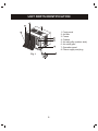
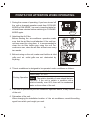
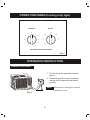
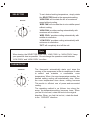
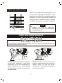
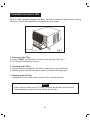
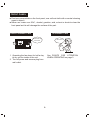
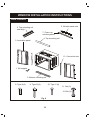
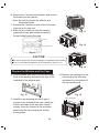
Keep Well This Manual.
Read Rules for Safe Operation and Instructions Carefully.
WINDOW - TYPE
AIR CONDITIONER
CONTENTS
1. ELECTRICAL SAFETY RULES..............................................................1
2. UNIT PARTS IDENTIFICATION..............................................................2
3. POINTS FOR ATTENTION WHEN OPERATING....................................3
4. OPERATION PANEL(Cooling only type).....................................................4
OPERATION INSTRUCTION..................................................................4
5. CARE AND MAINTENANCE...................................................................7
6. WINDOW INSTALLATION INSTRUCTIONS.........................................10
7. TROUBLESHOOTING TIPS...................................................................15
ELECTRICAL SAFETY RULES
CAUTION
All wiring must comply with local and national electrical codes and
be installed by a qualified electrician. If you have any questions
regarding the following instructions, contact a qualified electrician.
Never insert your fingers or any foreign objects into the air outlet.
Take special care to warn children of these dangers.
To avoid the possibility of personal injury, be sure to disconnect
power to the unit before installing and/or servicing and/or cleaning.
If the supply cord is damaged, it must be replaced by the manufacturer or its service agent or a similar qualified person in order to
avoid a hazard.
1. The power cord is distinguished according to the cord color:
2. For your safety and protection, this unit is grounded through the power cord plug
when plugged into a matching wall outlet. Please contact the manufacturer or its
service agent or a similar qualified person if you want to replace it.
3. Electrical requirement. (See the specifications)
4. Be sure that the unit being correctly grounded. The wall outlet should be provided
with reliable earth wire.
5. The unit should be provided with an individual branch circuit and the fuse size
should be same as that of the power cord plug and wall outlet.
1
UNIT PARTS IDENTIFICATION
1
3
4
1. Front panel
2. Air filter
3. Frame
4. Cabinet
5. Air inlet grille (outdoor side)
6. Air outlet grille
7. Operation panel
8. Power supply and plug
2
5
6
7
8
Fig. 1
2
POINTS FOR ATTENTION WHEN OPERATING
1. During the course of operating, if you have turned off
the unit or changed operation mode from COOLING
MODE to FAN MODE, be sure to keep that state for
at least three minutes before switching to COOLING
MODE again.
2. Attaching the Air Filter
Before starting the air conditioner operation, make
sure that the air filter is well attached. If the unit has
not been used for a long time, it is recommended to
clean the air filter before your using the unit. For
continuous use, clean the air filter at least once every
two weeks.
THREE
MINUTES
NO!
3. Before turning on the unit, make sure that the air inlet
grille and air outlet grille are not obstructed by
anything.
4. This air conditioner is designed to be operated under conditions as follows:
Outdoor temp.: 18-43 C
Indoor temp.: 21-32 C
Cooling Operation
Note: The relative humidity of room should be less
than 80%. If the unit is used in a condition with a
relative humidity over 80%, there will be condensed
water on the surface of the unit.
5. If the unit is operated beyond the conditions specified above, it may cause a failure
of the unit.
6. Relocation of the unit:
When changing the installation location of the air conditioner, consult the selling
agent from which you bought your unit.
3
OPERATION PANEL(Cooling only type)
THERMOSTAT
6
5
SELECTOR
OFF
7
HIGH
COOL
HIGH
FAN
8
4
9
3
10
2
1
MED
COOL
LOW
FAN
LOW
COOL
11
WAIT THREE MINUTES BEFORE RESTARTING
Fig. 2
OPERATION INSTRUCTION
OPERATION PANEL
1. Pull the top of the operation cover to
open it.
2. Close the operation cover and press
the top until it snaps into the locked
position.
Note: Don't press or swing the opened
operation cover.
Fig. 3
4
SELECTOR
To set desired cooling temperature, simply rotate
the SELECTOR knob to the appropriate setting.
"HIGH FAN" will circulate the air at a maximum
speed without cooling.
SELECTOR
"MED FAN" will circulate the air at a middle speed
without cooling.
OFF
HIGH
COOL
HIGH
FAN
MED
COOL
LOW
FAN
"HIGH FAN" provides cooling automatically with
maximum air circulation.
"MED COOL" provides cooling automatically with
middle air circulation.
LOW
COOL
"LOW COOL" provides cooling automatically with
minimum air circulation.
"OFF" will completely shut off the unit.
Note
When turning the SELECTOR knob from "LOW COOL" to "HIGH COOL", keep
your speed as slow as possible. Do not change the operation mode between
"LOW COOL" and "HIGH COOL" too often.
THERMOSTAT
THERMOSTAT
5
6
7
8
4
9
3
10
2
1
11
The thermostat automatically starts and stops the
running of the compressor in the air conditioner in order
to control and maintain a comfortable room
temperature. When the room temperature reaches the
desired setting, cooling will automatically stop. When
the room temperature rises above, cooling resumes.
This results in efficient use of power and economical
cooling.
The operating method is as follows: turn along the
arrow, the temperature setting becomes lower. When
you feel it is too cool, rotate the knob to the original
direction. When you feel it is too hot, rotate the knob
to the "COOLER" direction.
5
Note
During the cooling operation of the unit, when the thermostat knob is rotated
counterclockwise, allow at least three minutes before turning back the knob
to the "COOLER" direction. Otherwise the fuse may blow due to an
overload of the unit.
MANUAL LOUVER
Horizontal air flow adjustment (manually)
Move the "T" shaped handle left or right to
adjust horizontal air flow.
CLOSE
VENT.
Fig. 4
Vertical air flow adjustment (manually)
To adjust vertical air flow direction, adjust any one
of the horizontal louver blades.
Fig. 5
6
FRESH AIR VENTILATION
This is usually kept in the closed position and
use only when clearing smoke and/or odors
from the room. When the ventilation switch is
pushed to "CLOSE", the fresh air ventilation is
closed; when the ventilation switch is pushed
to "VENT", the fresh air ventilation is opened.
CLOSE
.
VENT.
Note
Keeping the fresh air ventilation
opened for a long time will reduce the
cooling effeciency.
Fig. 6
CARE AND MAINTENANCE
CAUTION
To avoid the possibility of personal injury, be sure to disconnect power to the unit
before servicing and/or cleaning.
CHEMICALS
Do Not use gasoline, benzene, thinner
or any other chemicals, or any liquid
insecticide on the air conditioner, as
these substances may cause flaking
off of the paint, cracking or deformation
of plastic parts.
Never attempt to clean the unit by
pouring water directly over any of the
surface areas, as this will cause
deterioration of electrical components
and wiring insulation.
7
CLEANING THE AIR FILTER
If the air filter becomes clogged with dust, air flow is obstructed and reduces cooling
efficiency. The air filter should be cleaned every two weeks.
6
3
9
WAI 1
T THR
EE
COOL
ER
MIN
UTE
HIGH
COO
L
MED
COO
L
OFF
LOW
COO
L
S BEF
ORE
LOW
FAN
HIGH
FAN
RES
TAR
TING
Push Here
Fig. 7
1. Removal of Air Filter
1) Press "PUSH" on the bottom corners of the inlet grill. See Fig. 7
2) Pull the air filter down to remove.
2. Cleaning of Air Filter
1) Remove the dust clogged in the filter by tapping it or vacuum clean it.
2) Wash the filter well with lukewarm water or a neutral cleaning agent.
3. Attaching the Air Filter
Installation of the air filter is the reverse of the removal process.
Note
Never use hot water over 40 C(104 F) to clean th e air filter and air fresher.
Never attempt to operate the unit without the air filter.
8
.
.
FRONT PANEL
Dust may accumulate on the front panel, use soft wet cloth with a neutral cleaning
agent to wipe it.
Never use water over 50 C, alcohol, gasoline, acid, solvent or brush to clean the
front panel as this will damage the surface of the part.
End-of Season Care
In-Season Care
OPERATING THE
FAN ALONE
SEE PAGE 3
See POINTS FOR ATTENTION
WHEN OPERATING on page 3.
1. Operating the fan alone for half a day
to dry out the inside of the unit.
2. Turn off power and remove plug from
wall outlet.
9
WINDOW INSTALLATION INSTRUCTIONS
Parts Insluded
5. Window sash seat
6. Top mounting rail
seal strip
7. Foam top
window gasket
4. Top mounting rail
3. Accordion panel
13. Connection bar
1. Sill support
2. Bottom mounting rail
8. Type A (4)
9. Type B (9)
10. Type C (8)
11. Nut (2)
12. Bolt (2)
Fig. 8
10
.
.
.
.
Window Requirements
5000 and 6000 BTU models
These instructions are for a standard
double-hung window. You will need to
modify them for other types of windows.
The air conditioner can be installed
without the accordion panels if needed to
fit in a narrow window. See the window
opening dimensions below.
All supporting parts must be secured to
firm wood, masonry or metal.
The electrical outlet must be within reach
of the power cord.
14" min.
22" to 30"
(With accordion panels)
17.5" min.
(Without accordion panels)
Fig. 9
Storm Window Requirements
A storm window frame will not allow the air
conditioner to tilt towards the outside and will
keep it from draining properly. To adjust for this,
attach a piece of wood to the stool.
WOOD PIECES--WIDTH: 2"
LENGTH: Long enough to fit inside the window
frame.
Wood
1 /2" higher
than frame
Stool
Storm window
frame
THICKNESS: To determine the thickness, place a
piece of wood on the stool to make it 1/ 2" higher
than the top of the storm window frame.
Attach securely with nails or screws provided by
the installer.
Remove the Air conditioner From the Case
1. Removal of Air Filter
A. Press "PUSH" on the bottom corners of the inlet grill.
Pull the air filter down to remove.
11
Fig. 10
B. Remove the 2 screws at the bottom, and remove
the frame from the cabinet.
Note: No need to remove the selector and
thermostat knobs.
C. Remove the 2 screws on each side of the case.
Keep these for later use.
D. Slide the air conditioner from the case by
gripping the base pan handle and pulling
forward while bracing the case.
Fig. 11
Foam
Fig. 12
Compressor
Fig. 13
CAUTION!
Be sure to remove the foam surrounding the compressor when installing.
If not, it would harm the operation of the compressor. (See Fig.13)
Fig. 14
Prepare the Window and the Case
A. Cut the window sash seal to the proper length.
Peel off the backing and attach the seal to the
underside of the window sash.
B. Remove the backing from the
top mounting rail seal strip
and attach it to the bottom of
the top mounting rail.
Fig. 16
Fig. 15
C. Install the top mounting rail with 4 type A
screws on the outside of the case. Install the
bottom rail inside of the case with 4 type C
screws. Insert the frames for the accordion
panels into the top mounting rail and the
frame guides.
12
Top mounting rail
Fig. 17
D. Install the Accordion panels
1 Attach the two Connection Bar to
the case.
2 Connect the shutter with the Connection
Bar.
Shutter
Connection Bar
Fig. 18
3 Insert the shutters into its frame bar.
And install the upper and lower frame
bars.
Fig. 19
4 Clip the shutters onto the frame bars
with the clips.
Upper Frame Bar
Left Frame Bar
Fig. 20
Fig. 21
Lower Frame Bar
Install the Case in the Window
A. Open the window and mark the centerline of
the window stool.
B. Carefully place the case on the window stool
and align the center mark on the bottom front
with the centerline of the stool.
C. Pull the window down behind the top mounting
rail.
NOTE: Do not shut the window so tightly that the movement
of the accordion panels is restricted.
Fig. 22
13
D. Loosely assemble the sill supports.
Indoor
Outdoor
Sill support
Bolt
E. Select the position that will place the sill
supports near the outermost point on the
sill. Attach the sill supports to the case
track hole in relation to the selected
position using 4 type C screws in each
supports.
Nut
Fig. 23
Frame guide
1/3"
Maximum
Fig. 24
F. Adjust the bolt and the nut in each support
so that the case is installed with a slight tilt
to the outside. Use a level; about 1/3" will
be the correct case slant to the outside.
G. Secure the case to the window stool by using
6 type B screws.
Sill support
Fig. 25
H. Pull the accordion panels to each window
sash track. Attach them on each side to
the window sash and the window stool
using 5 type B screws.
Fig. 26
Install the Window Locking Bracket and the Foam Top Window Gasket
A. Cut the foam top window gasket to the
window width.
B. Stuff the foam between the glass and
the window to prevent air and insects
from getting into the room.
Fig. 27
14
Install the Air Conditioner in the Case
The installation process is the reverse of the removal
process on page 11 and 12. See Fig 11.
Fig. 28
TROUBLESHOOTING TIPS
Save time and money! Review the chart below first and you may not need to call for
service.
Problem
Possible Causes
Air conditioner
does not start
The air conditioner is
unplugged.
.
.
.
What To Do
Make sure the air conditioner plug is pushed
completely into the outlet.
The fuse is blown/circuit
breaker is tripped.
Check the house fuse/circuit breaker box and
replace the fuse or reset the breaker.
Power failure.
If power failure occurs, turn the air conditioner
OFF. When power is restored, wait 3 minutes to
restart the air conditioner to prevent tripping of
the compressor overload.
15
Problem
Possible Causes
Air conditioner
does not cool
as it should
Airflow is restricted.
.
.
.
.
.
.
..
.
.
.
.
.
What To Do
Make sure there are no curtains, blinds or
furniture blocking the front of the air conditioner.
The temp control may
not be set correctly.
On models with touch pads: In COOL mode,
press the DECREASE pad.
On modes with control knobs, turn the
temperature knob to a higher number.
The air filter is dirty.
Clean the filter at least every 30 days. See the
Operating Instructions section.
When the air conditioner is first turned on you
need to allow time for the room to cool down.
Check for open furnace and cold
air returns.
Set the air conditioner's vent to the closed
See "Air conditioner freezing up" below.
The room may have been
hot.
Cold air is escaping.
Cooling coils have iced
up.
Air conditioner
freezing up
Ice blocks the air flow and
stops the air conditioner
from cooling the room.
On models with control knobs, set the mode
control at HIGH FAN or HIGH COOL with the
temp at 1 or 2.
On models with touch pads, set the controls at
HIGH (F3) FAN or HIGH (F3) COOL and set the
thermostat to a higher temperature.
Water drips outside Excessively hot and humid
weather.
This is normal.
Water drips indoors The air conditioner is not
tilted to the outside.
Water collects in
base pan
Normal Operating
Sounds
For proper water disposal, make sure the air
conditioner slants slightly from the case front to
the rear.
Moisture is removed from
indoor air and drains into
rear of a cabinet where a
fan blows it against the
outdoor condenser coil.
This is normal for a short period in areas with
little humidity; normal for a longer period in very
humid areas.
You may hear a pinging noise caused by water being picked up and thrown
against the condenser on rainy days or when the humidity is high. This design
feature helps remove moisture and improve efficiency.
You may hear the thermostat click when the compressor cycles on and off.
Water will collect in the base pan during high humidity or on rainy days. The
water may overflow and drip from the outdoor side of the unit.
The fan may run even when the compressor does not.
16
CS45-U
2200019260