1
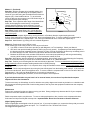
Installation, Compensation, and Maintenance Instructions
For all
RITCHIE® HELMSMAN™
Compass Models
Made in U.S.A.
CAUTION:
All Magnetic Compasses are vulnerable to magnetic interference, which will produce errors, called deviation.
It is the Owner/Operator and/or Helmsman’s responsibility to make sure the compass is properly installed
and compensated. Compensation is the act of correcting for deviation. Magnets (speakers, microphones
etc.), ferrous metals (steel, iron, etc.) and current carrying devices are common causes of deviation. It is
important to understand that magnetic compasses point toward Magnetic North. There is a difference
between Magnetic North and True North, and that difference is called variation. Variation differs depending
on your geographical location and can be determined by referring to a local chart.
Please read the Instructions completely before beginning installation.
Selecting the Proper Location
The compass should be close enough to the helmsman and positioned below the helmsman's line of sight so it is
easily read during normal operation. Direct Read Dial or CombiDamp Dial models will allow the compass to be
mounted higher, near or at eye level.
You will need a flat and level surface (when the boat is on a level keel). Many boats have a curved mounting surface
and if this is the case, a fairing block should be utilized to bring the compass to a level position.
Select a location that has no more that 20 degrees deviation on any of the four cardinal points (N S E and W). Most
compasses have a built in compensation system that will correct for fixed deviation up to 20 degrees. It is important
to realize that proper compensation is not possible when a compass is subjected to a magnetic field that is variable.
Some shipboard devices can cause varying magnetic fields. Devices such as windshield wipers, high current carrying
wire and even some steering wheels must be considered when selecting a location for your compass.
Testing Your Chosen Location
Use your compass to test a location. There are two brass rods near the bottom of the compass which rotate 360
degrees, the slotted ends may be all that is visible. These compensation rods are used to correct your compass
for deviation. When testing a location, you do not want pre-set corrections in your compass, so neutralize the comprods by setting the slots in a horizontal position.
Begin your test by holding the compass away from any possible interference and observing the compass reading.
Then move the compass into position carefully; keeping it pointed in the same direction. If the compass reading is
different without a change in direction you are observing deviation. You need to find a location that has less than 20
degrees of deviation on the 4 cardinal points if you intend to adjust your compass using the compensator rods.
After finding a location you should test for intermittent changes in the magnetic field. With the compass mounted
temporarily in its intended position try moving the steering wheel, throttle controls or anything else that might cause
deviation. It is also advised to turn electrical devices off and on. Please be advised that a changing magnetic field
can not be corrected with compensation and you will need to find another location for your compass.
Installation (all Models)
Mounting the Compass
Great care must be taken to mount the compass so that it is aligned with the keel of the boat. An alignment error is
a constant error on all headings caused by the compass not being pointed in the same direction as the boat.
One recommendation is to temporarily mount the compass using one fastener so if an alignment error is detected it is
easily corrected. Masking tape can be used as a reference or to keep the compass steady during installation.
If you are mounting to a bulkhead that is not perpendicular to the centerline of the boat, a fairing block must be used.
Due to variations in bulkhead and deck materials, mounting screws are not supplied. Use hardware that is suitable for
your specific installation. SELECT MOUNTING HARDWARE THAT IS NON-MAGNETIC. Most quality stainless steel
and solid brass fasteners can be used. If you are unsure test them with a magnet.
Most models have built-in lights which will require routing the wire or wires to your power source. To assure a clean
installation you may want to wait and drill the routing holes after you are satisfied with the compass alignment.
Specific model installation instructions are as follows:
Note for all flush and bulkhead mount compasses:
It is important that you use the mounting gasket included with each model. We do NOT recommend the use of
bedding compound since some brands contain chemicals that could damage the plastic dome.
HF-72, HF-72W, HF-73, HF-73W, HF-79, HF-79G, HF-79W, SS-1000& SS-1000W Flush Mount
Using the mounting template supplied with the compass, make the cutout in your chosen location and mount as
instructed above (Mounting the Compass). For all HF-79 models, loosen but do NOT remove the single screw in the
rear of the dress-bezel. Lift the rear of the dress-bezel and slide it forward to remove it from the compass. When
mounting and compensation are completed, replace the dress-bezel. Note: If you cannot access the compensation
rods from below you need to allow for easy removal of the compass during compensation. (See Compensation
instructions below).
HV-76 & HV-77 Bulkhead Mount
Before making the cut, make sure the bulkhead surface at the mounting location is at a ninety-degree (90°)
angle to the centerline of the boat and is in a vertical position. If such is not the case, a fairing block must
be used between the compass and the bulkhead. Use the mounting template supplied with the compass
for cutting the necessary opening in the vertical bulkhead. If the compass is not mounted in a vertical
position, serious errors can develop when the boat heels over and pitching occurs simultaneously. There
is also potential error from the built-in compensator magnets if the compass is not mounted vertically.
HD-74, HD-75 & SS-1100 Deck Mount
Follow the instructions above (Mounting the Compass). After mounting, remove the black plastic inserts and
begin compensation (see Compensation instructions below).
HB-70, HB-71 & HB-85 Bracket Mount
Remove the bracket from the compass and mount it as instructed above (Mounting the Compass). If you mounted
the bracket to a gunwale simply rotate the compass 90 degrees in it’s housing by removing the four Phillips head
screws located in the bottom of the housing. After re-installing the compass in the bracket remove the black plastic
inserts, which cover the compensators and begin compensation (see Compensation instructions below).
IMPORTANT NOTE REGARDING HB-85
This model is designed to be mounted on STEEL HULL Vessels. Special compensation is required and you will need
to hire a professional compass adjuster.
Night Light Wiring (all Models)
All models are supplied with a 12-volt night lighting system. To connect lights to a 24 or 32-volt system, dropping
resistors are available.
Lights should be wired to an appropriately fused 12-volt circuit in your electrical system (i.e. running light circuit).
Connect the red wire (white on some models) to positive and black to ground. Some models have a second light
assembly, which should be connected to the same circuit.
Compensation
A built-in correcting magnet system consists of two sets of magnets fixed to two adjusting rods with slotted ends. The
slots should be horizontal before starting the adjusting procedure. A small non-magnetic screwdriver is provided for
this purpose.
Before starting compensation, make sure you have a suitable location (see Testing Your Chosen Location).
Method 1. (Preferred)
Step One. With the compass in its intended position, but
LIGHTHOUSE
not finally secured, (see Mounting the Compass) select a
course on your chart using two fixed aids that are within ten
degrees (10°) of the North/South line. Try to select this
course so that you can maneuver your boat “down range” of
the marks selected (See example).
LIGHTHOUSE
TOWER
Step Two. From a position down range of the North/South
marks, and keeping the marks lined up, run the boat
visually along the Northerly course selected. Turn the
port/starboard compensator (slot is facing starboard) until
the compass reads correctly.
DOWN RANGE
Step Three. Simply repeat steps 1 & 2, except this time,
EXAMPLE
using an East/West course and the fore/aft compensator
(slot is facing aft).
Step Four. Check compass alignment by running the boat in a Southerly direction, again keeping the mark
lined up. If the compass is not correct at this time, there is an alignment error. To correct, rotate the compass itself to
remove one half of this error. Repeat steps 1, 2 & 4 until your North/South line is correct then repeat step 3.
Step Five. Install fastener (s), taking care not to disturb alignment.
Method 2. (Requires the use of GPS or Loran)
In this method you will be using a GPS or Loran as your reference.
1. Your GPS or Loran must be set to provide you with Magnetic, not True headings. Check your Manual.
2. GPS and Loran provide headings based on COG (course over ground). Compasses provide heading based on
the direction the boat is actually pointed. Because of Tides, Currents and Winds, the boat may not always point in
the same direction as COG. Pick a time and location that will minimize these effects.
3. Because the GPS and Loran calculate COG based on current and past positions you will see greater heading
accuracy while traveling at higher speeds. We recommend at least 10 knots.
Step One. While at sea, with the compass in its intended position, but not finally secured, (see Mounting the Compass),
o
obtain the Loran/GPS bearing to a fixed aid or landmark that is within 10 of a North/South line.
Step Two. Position your boat along that line and steer directly at that mark. Turn the port/starboard compensator (slot is
facing starboard) until the compass heading matches the Loran/GPS bearing.
Step Three. Simply repeat steps 1 & 2, except this time, using an East/West course and the fore/aft compensator (slot is
facing aft).
Step Four. Check compass alignment by running the boat 180 degrees from the heading used in step 2. If the compass
is not correct at this time, there is an alignment error. To correct, rotate the compass itself to remove one half of this error.
Repeat steps 1, 2 & 4 until your North/South line is correct then repeat step 3.
Step Five. Upon completing the procedure, secure the compass in its final position.
If you feel that the deviation on your boat is of an unusual nature, the services of a professional compass
adjuster will be a wise investment.
To assure accuracy on all headings, check for deviation every thirty degrees and record any deviation on a deviation card.
We recommend checking at the start of each boating season, and any time new equipment is added near the compass,
for deviation.
Maintenance
Protect your compass from the sun when not using your boat. Strong sunlight may decrease the life of your compass.
Custom fit covers are available from Ritchie.
Ritchie compasses require very little care. To remove salt spray deposits or dirt, rinse the entire compass with clean,
fresh water and wipe carefully with a damp cloth. Important Note: Never Use Chemical or Abrasive Cleaners.
Night Lighting Systems
Ritchie’s night-lights are designed to last for years of use. If you need to replace one, contact the factory with your model
and serial number for a part number and price. Tel. 781-826-5131 Fax. 781-826-7336 E-mail
[email protected]
Warranty:
We warrant all Ritchie Magnetic Marine Compasses to be free of defects in workmanship or materials. If within three
years of purchase date, a compass fails to give satisfactory service, it will be repaired or replaced without charge. This
warranty does not cover breakage through accident or misuse. Replacement or repair will be made if the instrument is
returned prepaid to a Ritchie Service Station or directly to E.S. Ritchie & Sons, Inc., 243 Oak Street, Pembroke, MA
02359.
RITCHIE NAVIGATION
E.S. RITCHIE & SONS, INC., P.O. BOX 548, 243 OAK ST., PEMBROKE, MASSACHUSETTS 02359 U.S.A.
Tel. (781) 826-5131 Fax (781) 826-7336
www.ritchienavigation.com
Rev D 4/00
HL-0032
Printed in U.S.A.