1
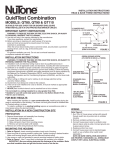
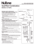
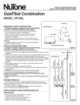
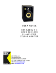
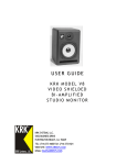
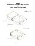
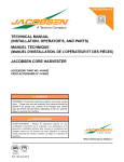
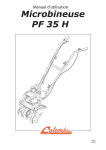
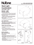
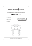
INSTALLATION INSTRUCTIONS
READ & SAVE THESE INSTRUCTIONS!
SmartSense Combination
™
MODEL: QT110H
SUITABLE FOR USE OVER TUB OR SHOWER ENCLOSURE
WHEN INSTALLED IN A GFCI PROTECTED BRANCH CIRCUIT.
IMPORTANT SAFETY INSTRUCTIONS
WARNING: TO REDUCE THE RISK OF FIRE. ELECTRIC SHOCK,
OR INJURY TO PERSONS, OBSERVE THE FOLLOWING:
A. Use this unit only in the manner intended by the manufacturer. If you
have questions, contact the manufacturer.
B. Before servicing or cleaning unit, switch power off at service
panel and lock service panel to prevent power from being
switched on accidentally.
When the service disconnecting means cannot be locked, securely
fasten a prominent warning device, such as a tag, to the service
panel.
CAUTION:
For general ventilating use only. Do not use to exhaust hazardous
or explosive materials and vapors.
INSTALLATION INSTRUCTIONS
WARNING: TO REDUCE THE RISK OF FIRE, ELECTRIC SHOCK,
OR INJURY TO PERSONS, OBSERVE THE FOLLOWING:
A. Installation work and electrical wiring must be done by qualified
person(s) in accordance with all applicable codes and standards,
including fire-rated construction.
B. Sufficient air is needed for proper combustion and exhausting of
gases through the flue (chimney) of fuel burning equipment to prevent
back drafting. Follow the heating equipment manufacturer's guideline
and safety standards such as those published by the National Fire
Protection Association (NFPA), and the American Society for
Heating, Refrigeration and Air Conditioning Engineers (ASHRAE),
and the local code authorities.
C. When cutting or drilling into wall or ceiling, do not damage electrical
wiring and other hidden utilities.
D. Ducted fans must always be vented to the outdoors.
E. If this unit is to be installed over a tub or shower, it must be marked
as appropriate for the application and be connected to a GFCI
(Ground Fault Circuit Interrupter) - protected branch circuit.
F. NEVER place a switch where it can be reached from a tub or shower.
G. Handle the sensor unit with care. Avoid direct contact with electronic
components while installing.
• Do not install in a ceiling insulated to a value greater than R40.
• Not for use in kitchens.
FOR BEST RESULTS
When installing the Ventilator in a new construction site, install
housing during the rough-in construction of the building. The blower unit,
sensor unit and grille should be installed after the finished ceiling is in
place.
To install a ventilator in an existing building requires an accessible
area (attic or crawl space) above the planned location.
This unit is designed to detect increased humidity levels and to
automatically activate the fan. For best results, the fan should be located
near the humidity source. Increasing the distance from the source will
lengthen the response time of the unit.
4" DIAMETER DUCT
(CONDUIT DE 4 PO DE DIAMÉTRE)
ROOF CAP
(COUVERCLE DE TOÎT)
90° ELBOW
(COUDE À 90°)
WALL CAP
(COUVERCLE MURAL)
CEILING INSTALLATION
(POSE AU PLAFOND)
FIGURE 1
INSTALLATION IN A NEW CONSTRUCTION SITE
PREPARATION
1. Remove blower/power unit assembly from housing:
A. If necessary, unplug power unit.
B. Loosen three (3) mounting screws.
C. Slide unit back to free it from mounting screws.
D. Remove unit and set aside until needed.
2. Remove one of the wiring knockouts from housing.
MOUNTING THE HOUSING
1. Refer to Figure 4. Insert mounting brackets at each end of housing.
2. Place long side of housing parallel to ceiling joist. Position housing in
desired location. Make sure housing flange is even with the planned
finished ceiling.
3. Use screws or nails (not provided) to secure mounting brackets to
ceiling joists.
4. Refer to Figure 1. Use 4" round duct to discharge the ventilator to the
outside.
IMPORTANT: Be sure nothing obstructs the discharge of the
ventilator. Make sure that insulation does not get into the duct work
or into the fan.
CONNECTOR
BLACK
BLUE
AC
ITE
WH
BL
BLACK
120 VOLT
AC SUPPLY
K
WHITE
WHITE
JUNCTION
BOX COVER
JUNCTION BOX
WIRING CONNECTIONS
MOTOR PLUG
FIGURE 2
SENSOR COVER TABS
WIRING
Refer Figure 2.
1. Run 120v AC house power wiring (with ground) through switch box to
junction box in ventilator housing.
2. Remove ventilator junction box cover.
3. Referencing figure 2 connect the house power wire (black) to the
connector black wire. Connect the house neutral wire (white) to both
the connector and motor plug wires (white). Connect the ground wire
to the green ground screw. Connect the blue connector wire to the
black motor plug wire.
4. Replace junction box cover.
5. Connect house power wire to standard toggle switch.
NOTE: BE SURE VENTILATOR AND SWITCH ARE PROPERLY
GROUNDED. ALL WIRING MUST COMPLY WITH LOCAL
ELECTRICAL CODES.
SENSOR UNIT INSTALLATION
Refer Figure 3.
1. Align sensor cover tabs with slots in junction box cover. Firmly
press sensor cover to engage connector.
2. Secure sensor unit using mounting screw through hole in unit
cover flange.
POWER/BLOWER UNIT INSTALLATION
1. Plug motor into socket in housing's junction box.
2. Position power unit mounting plate over mounting screws in
housing.
3. Slide unit forward until the gasket fits firmly against discharge
opening in housing and mounting screws are seated in narrow
end of keyhole slots.
4. Refer to Figure 4. Securely tighten screws.
GRILLE INSTALLATION
1. Refer to Figure 4. Snap grille mounting springs' center loop into
notched bosses on the back of grille.
2. Place grille mounting springs into slots in power unit mounting
plate.
3. Press grille firmly into place against the ceiling.
SENSOR
UNIT
TIMER ADJUSTMENT
FIGURE 3
INSTALLATION IN EXISTING CONSTRUCTION
Installing the ventilator in an existing house requires an accessible
area (attic crawl space) above the planned installation location.
Review “INSTALLATION IN A NEW CONSTRUCTION” and
follow all instructions which apply to your installation.
Location – locate ventilator parallel to a ceiling joist.
Wiring and Ducting – plan ducting and wiring before proceeding
with installation.
Refer to Figure 2 for wiring and Figure 1 for ducting.
CAUTION: Check area above planned installation to be sure that:
1. Ducting can be installed.
2. Wiring can be run to the planned location.
3. No wiring or other obstructions might interfere with
installation.
INSTALLATION FROM ACCESSIBLE
AREA ABOVE
1. From below, drill a small hole in ceiling at the planned location.
Stick clothes hanger through hole to help locate it.
2. Locate hole in attic or crawl space.
3. In attic or crawl space, mark ceiling for cutout by using the
housing as a template. The long side of cutout must be parallel
to ceiling joist.
4. Make cutout along marked line.
NOTE: If ceiling is plaster, cutout should be made from below
to avoid chipping plaster.
5. Install housing, connect wiring and ducting, install sensor unit,
install power unit/blower assembly and install grille.
DISCHARGE OPENING
(OUVERTURE DE DÉCHARGE
WIRING KNOCKOUT
(DÉBOUCHURE)
HOUSING
(BOÌTIER)
MOUNTING
BRACKET
(PATTE DE
FDCATION)
MOUNTING SCREWS
(VIS DE MONTAGE)
POWER UNIT MOUNTING PLATE
(PLAQUE DE MIONTAGE DU
MOTEUR
MOUNTING SPRING
(RESSORT DE
MONTAGE)
GRILLE
(LA GRILL)
NOTCHED BOSS
(BOSSAGE CRANTE)
MOUNTING SPRING
(RESSORT DE MONTAGE)
FIGURE 4
SENSOR OPERATION AND CARE
The SmartSense™ humidity sensing fan is designed to sense
changes in room humidity and to automatically activate the fan.
The humidity sensor unit continually monitors humidity levels and
continues to operate the fan until humidity levels return to normal.
The length of time that the unit operates after humidity levels have
normalized is user adjustable.
Note: When power is first applied to the unit the fan will
operate for approximately 5 minutes (or longer depending
upon timer control setting. See below). After the initial
operation the unit will operate automatically when humidity
level changes trigger the sensor. Leave wall switch in ON
position for normal operation. Power should be removed
during servicing.
TIMER ADJUSTMENT
The humidity sensor control timer can be adjusted to operate the
fan from approximately 5 to 20 minutes after humidity levels have
returned to normal. To adjust the delay time:
1. Disconnect power to the ventilator.
2. Remove the ventilator grille.
3. Using a small flat-blade screwdriver, slowly rotate the timer
control (located in one corner of the ventilator - see figure 3)
to the desired point.4. Replace the grill and turn on the power.
Note: The delay time should be adjusted to suit the specific
conditions of your application. Observe room moisture levels
and allow adequate time after visible condensation has been
removed to assure that residual moisture has been eliminated.
SENSOR CLEANING
The humidity sensor is permanently mounted in the control unit and
is visible in one corner of the ventilator behind the grille.
Periodically check and clean the sensor as follows:
1. Disconnect power to the ventilator.
2. Remove the ventilator grille.
3. Locate the sensor. Gently remove accumulated dirt or
lint using a cotton swab.
4. Replace the grille and turn on power.
One Year Limited Warranty
WARRANTY OWNER: NuTone warrants to the original consumer purchaser of its products that such products will be free from defects in materials or workmanship for a period
of one (1) year from the date of original purchase. THERE ARE NO OTHER WARRANTIES, EXPRESS OR IMPLIED, INCLUDING, BUT NOT LIMITED TO, IMPLIED
WARRANTIES OF MERCHANTABILITY OR FITNESS FOR A PARTICULAR PURPOSE.
During this one year period, NuTone will, at its option, repair or replace, without charge, any product or part which is found to be defective under normal use and service.
THIS WARRANTY DOES NOT EXTEND TO FLUORESCENT LAMP STARTERS OR TUBES, FILTERS, DUCT, ROOF CAPS, WALL CAPS AND OTHER ACCESSORIES
FOR DUCTING. This warranty does not cover (a) normal maintenance and service or (b) any products or parts which have been subject to misuse, negligence, accident,
improper maintenance or repair (other than by NuTone), faulty installation or installation contrary to recommended installation instructions.
The duration of any implied warranty is limited to the one year period as specified for the express warranty. Some states do not allow limitation on how long an implied warranty
lasts, so the above limitation may not apply to you.
NUTONE’S OBLIGATION TO REPAIR OR REPLACE, AT NUTONE’S OPTION, SHALL BE THE PURCHASER’S SOLE AND EXCLUSIVE REMEDY UNDER THIS
WARRANTY. NUTONE SHALL NOT BE LIABLE FOR INCIDENTAL, CONSEQUENTIAL OR SPECIAL DAMAGES ARISING OUT OF OR IN CONNECTION WITH
PRODUCT USE OR PERFORMANCE. Some states do not allow the exclusion or limitation of incidental or consequential damages, so the above limitation or exclusion may
not apply to you. This warranty gives you specific legal rights, and you may also have other rights, which vary from state to state. This warranty supersedes all prior warranties.
WARRANTY SERVICE: To qualify for warranty service, you must (a) notify NuTone at the address stated below or telephone 1/800-543-8687, (b) give the model
number and part identification and (c) describe the nature of any defect in the product or part. At the time of requesting warranty service, you must present
evidence of the original purchase date.
Date of Installation
Builder or Installer
Model No. and Product Description
IF YOU NEED ASSISTANCE OR SERVICE:
For the location of your nearest NuTone Independent Authorized Service Center:
Residents of the contiguous United States Dial Free 1-800-543-8687
Please be prepared to provide:
Product model number • Date and Proof of purchase • The nature of the difficulty
Residents of Alaska or Hawaii should write to: NuTone Inc. Attn: Department of National Field Service, 4820 Red Bank Road, Cincinnati Ohio 45227-1599.
Residents of Canada should write to: Broan-NuTone Canada, 1140 Tristar Drive, Mississauga, Ontario, Canada L5T 1H9.
Rev. 03/2001
Product specifications subject to change without notice.
4820 Red Bank Road, Cincinnati, Ohio 45227-1599
Printed in U.S.A., Rev. 5/2001, Part No. 89697