1
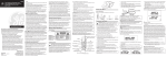
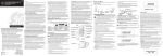
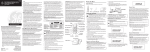
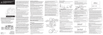
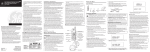
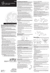
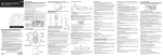
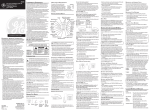
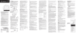
21009
Extra Handset and Recharge Cradle
with Call-Waiting Caller ID for Use with
Models 21018, 21028 and 21098
User’s Guide
•
•
•
•
We bring good things to life.
EQUIPMENT APPROVAL INFORMATION
Your telephone equipment is approved for connection to the Public
Switched Telephone Network and is in compliance with parts 15 and
68, FCC Rules and Regulations and the Technical Requirements for
Telephone Terminal Equipment published by ACTA.
1 Notification to the Local Telephone Company
On the bottom of this equipment is a label indicating, among
other information, the US number and Ringer Equivalence
Number (REN) for the equipment. You must, upon request,
provide this information to your telephone company.
CAUTION:
RISK OF ELECTRIC SHOCK
DO NOT OPEN
WARNING: TO
PREVENT FIRE OR
ELECTRICAL SHOCK
HAZARD, DO NOT
EXPOSE THIS
PRODUCT TO RAIN
OR MOISTURE.
Model 21009
00001583 (Rev. 0 E)
04-31
Printed in China
THE LIGHTNING
FLASH AND ARROW
HEAD WITHIN THE
TRIANGLE IS A
WARNING SIGN
ALERTING YOU OF
“DANGEROUS
VOLTAGE” INSIDE
THE PRODUCT.
CAUTION: TO REDUCE THE
RISK OF ELECTRIC SHOCK, DO
NOT REMOVE COVER (OR
BACK). NO USER
SERVICEABLE PARTS INSIDE.
REFER SERVICING TO
QUALIFIED SERVICE
PERSONNEL.
THE EXCLAMATION
POINT WITHIN THE
TRIANGLE IS A
WARNING SIGN
ALERTING YOU OF
IMPORTANT
INSTRUCTIONS
ACCOMPANYING
THE PRODUCT.
SEE MARKING ON BOTTOM / BACK OF PRODUCT
ATLINKS USA, Inc.
101 West 103rd Street
Indianapolis, IN 46290
© 2004 ATLINKS USA, Inc.
Trademark(s) ® Registered
Marca(s) Registrada(s)
2
The REN is useful in determining the number of devices you may
connect to your telephone line and still have all of these devices
ring when your telephone number is called. In most (but not all)
areas, the sum of the RENs of all devices connected to one line
should not exceed 5. To be certain of the number of devices you
may connect to your line as determined by the REN, you should
contact your local telephone company.
A plug and jack used to connect this equipment to the premises
wiring and telephone network must comply with the applicable
FCC Part 68 rules and requirements adopted by the ACTA. A
compliant telephone cord and modular plug is provided with this
product. It is designed to be connected to a compatible modular
jack that is also compliant. See installation instructions for
details.
Notes
This equipment may not be used on coin service provided by the
telephone company.
Party lines are subject to state tariffs, and therefore, you may not
be able to use your own telephone equipment if you are on a
party line. Check with your local telephone company.
Notice must be given to the telephone company upon permanent
disconnection of your telephone from your line.
If your home has specially wired alarm equipment connected to
the telephone line, ensure the installation of this product does
not disable your alarm equipment. If you have questions about
what will disable alarm equipment, consult your telephone
company or a qualified installer.
Rights of the Telephone Company
Should your equipment cause trouble on your line which may
harm the telephone network, the telephone company shall, where
practicable, notify you that temporary discontinuance of service
may be required. Where prior notice is not practicable and the
circumstances warrant such action, the telephone company may
temporarily discontinue service immediately. In case of such
temporary discontinuance, the telephone company must: (1)
promptly notify you of such temporary discontinuance; (2) afford
you the opportunity to correct the situation; and (3) inform you of
your right to bring a complaint to the Commission pursuant to
procedures set forth in Subpart E of Part 68, FCC Rules and
Regulations.
The telephone company may make changes in its
communications facilities, equipment, operations or procedures
where such action is required in the operation of its business and
not inconsistent with FCC Rules and Regulations. If these changes
are expected to affect the use or performance of your telephone
equipment, the telephone company must give you adequate
notice, in writing, to allow you to maintain uninterrupted service.
FCC RF RADIATION EXPOSURE STATEMENT
This equipment complies with FCC RF radiation exposure limits set
forth for an uncontrolled environment. This equipment should be
installed and operated with a mininum distance of 20 centimeters
between the radiator and your body. This transmitter must not be colocated or operated in conjunction with any other antenna or
transmitter.
For body worn operation, this phone has been tested and meets the
FCC RF exposure guidelines when used with the belt clip supplied
with this product. Use of other accessories may not ensure
compliance with FCC RF exposure guidelines.
INTERFERENCE INFORMATION
This device complies with Part 15 of the FCC Rules. Operation is
subject to the following two conditions: (1) This device may not
cause harmful interference; and (2) This device must accept any
interference received, including interference that may cause
undesired operation.
This equipment has been tested and found to comply with the limits
for a Class B digital device, pursuant to Part 15 of the FCC Rules.
These limits are designed to provide reasonable protection against
harmful interference in a residential installation.
This equipment generates, uses, and can radiate radio frequency
energy and, if not installed and used in accordance with the
instructions, may cause harmful interference to radio
communications. However, there is no guarantee that interference
will not occur in a particular installation.
If this equipment does cause harmful interference to radio or
television reception, which can be determined by turning the
equipment off and on, the user is encouraged to try to correct the
interference by one or more of the following measures:
• Reorient or relocate the receiving antenna (that is, the antenna
for radio or television that is “receiving” the interference).
• Reorient or relocate and increase the separation between the
telecommunications equipment and receiving antenna.
• Connect the telecommunications equipment into an outlet on a
circuit different from that to which the receiving antenna is
connected.
If these measures do not eliminate the interference, please consult
your dealer or an experienced radio/television technician for
additional suggestions. Also, the Federal Communications
Commission has prepared a helpful booklet, “How To Identify and
Resolve Radio/TV Interference Problems.” This booklet is available
from the U.S. Government Printing Office, Washington, D.C. 20402.
Please specify stock number 004-000-00345-4 when ordering copies.
HEARING AID COMPATIBILITY
This telephone system meets FCC standards for Hearing Aid
Compatibility.
• know who called while you are on the other line or when you
were away.
• screen unwanted calls, eliminate harassment from annoying
calls, or to get prepared before answering a call.
Congratulations on purchasing this extra GE cordless handset with Call
Waiting Caller ID. This telephone has been designed to be simple to
use, however, you can reach its full potential more quickly by taking a
few minutes to read this instruction book. This telephone is a
multifunction product for use with Call Waiting and Caller ID services
available from your local telephone company.
IMPORTANT: In order to use all of the features of this
telephone, you must subscribe to two separate services available
from your local telephone company: the standard Name/
Number Caller ID Service to know who is calling when the
phone rings and Call Waiting Caller ID Service to know who is
calling while you are on the phone.
INSTALLATION NOTE: Some cordless telephones operate at
frequencies that may cause interference to nearby TVs, microwave
ovens, and VCRs. To minimize or prevent such interference, the
base of the cordless telephone should not be placed near or on top
of a TV, microwave ovens, or VCR. If such interference continues,
move the cordless telephone farther away from these appliances.
Certain other communications devices may also use the 2.4 GHz
frequency for communication, and, if not properly set, these
devices may interfere with each other and/or your new telephone.
Typical devices that may use the 2.4 GHz frequency for
communication include wireless audio/video senders, wireless
computer networks, multi-handset cordless telephone systems, and
some long-range cordless telephone systems.
HANDSET AND CHARGE CRADLE LAYOUT
Make sure your package includes the items shown here.
display
del
(delete button)
TALK/END/callback
(button)
format/conf button
(format/conference button)
cid/vol (up or down arrow)
(caller ID/volume button)
SPKR
(speaker button)
*exit (button)
redial (button)
#pause/ringer
(button)
mem
(memory button)
flash (button)
page/int
page/intercom button mute/prog
(mute/program button)
BLACK WIRE
Handset
Belt
Clip
Handset charge
Battery
Handset
cradle
compartment battery pack
cover
INSTALLING THE PHONE
IMPORTANT: Make sure the extra handset is registered
to GE Models 21018, 21028 or 21098 before use. Refer
to the GE 21018, 21028 or 21098 instruction book for
detailed installation and operation information.
• Never install telephone wiring during a lightning storm.
• Never install telephone jacks in wet locations unless the jack is
specifically designed for wet locations.
• Never touch non-insulated telephone wires or terminals, unless
the telephone line has been disconnected at the network
interface.
• Use caution when installing or modifying telephone lines.
• Temporarily disconnect any equipment connected to the phone
such as faxes, other phones, or modems.
• Install telephone near an electrical power outlet.
• Avoid sources of noise, such as a window by a busy street, and
electrical noise, such motors, microwave ovens, and fluorescent
lighting.
• Avoid heat sources, such as heating air ducts, heating appliances,
radiators, and direct sunlight.
• Avoid areas of excessive moisture or extremely low temperature.
• Avoid dusty locations.
• Avoid other cordless telephones or personal computers.
1. Plug the charge cradle power supply into an electrical outlet.
2. Install the handset battery.
NOTE: You must connect the handset battery before use.
• Push down on the top of the battery compartment cover (located
on the back of each handset) and remove the cover.
• Lift the battery pack and connect it's plug to the jack inside the
compartment.
NOTE: It is important to maintain the polarity (black and red
wires) to the jack inside the compartment as shown in the
illustration.
AC power supply
charge indicator
• Close the battery compartment by pushing the cover up until it
snaps into place.
• Place the handset in the charging cradle. The charge indicator
turns on to indicate the battery is charging.
• Allow the handset to charge for 16 hours prior to registration to
GE Models 21018, 21028 or 21098. If you don't properly charge the
phone, battery performance is compromised.
BATTERY
IMPORTANT INSTALLATION GUIDELINES
Your Call Waiting Caller ID phone allows you to:
• view the name and telephone number of a caller while you are on
the phone (Call Waiting Caller ID).
• identify callers before you answer the phone.
• view the time and date of each incoming call.
• record up to 40 Caller ID messages sequentially in each handset
and the base.
PARTS CHECKLIST
IMPORTANT: Because cordless phones operate on electricity,
you should have at least one phone in your home that isn’t
cordless, in case the power in your home goes out.
INTRODUCTION
CAUTION: When using telephone equipment, there are
basic safety instructions that should always be followed. Refer
to the IMPORTANT SAFETY INSTRUCTIONS provided
with this product and save them for future reference.
BEFORE YOU BEGIN
PRESS DOWN
FIRMLY
RED WIRE
NOTE: If the battery is not properly installed in the handset, or
if the battery pack is not properly connected to the jack inside
the battery compartment. "NO BATTERY" shows in the display
when the handset is placed in the charging cradle.
IMPORTANT: After you place the handset in the cradle the
display shows "CHARGING...", then, "SEARCHING...", then
"HANDSET NEEDS REGISTRATION" alternately. Wait until the
handset charges properly, then register the handset to the base as
described below.
PROGRAMMING THE TELEPHONE
HANDSET REGISTRATION
CAUTION: The extra handset must be registered before use.
NOTE: This extra handset is only compatible with the GE
Models 21018, 21028 and 21098 series.
During the registration process, keep your handset near the base.
When your handset displays:
HANDSET #
REGISTERED
HANDSET NAME
3. The handset number (1 to 4) is assigned. You may also give the
handset a specific identifying name.
HANDSET NAME
1. Use the touch-tone keypad to enter the name (up to 15 characters).
More than one letter is stored in each of the number keys. For
example, to enter the name Bill Smith, press the 2 key twice for
the letter B. Briefly pause and the cursor moves to the next field.
Press the 4 key 3 times for the letter I. Briefly pause and the
cursor moves to the next field. Press the 5 key 3 times for the
second letter L. Briefly pause and the cursor moves to the next
field. Press the 5 key 3 times for the second letter L, press 1 key to
add a space between the first and last name. Press the 7 key 4
times for the letter S. Briefly pause and the cursor moves to the
next field. Press the 6 key once for the letter M. Briefly pause and
the cursor moves to the next field. Press the 4 key 3 times for the
letter I. Briefly pause and the cursor moves to the next field. Press
the 8 key for the letter T. Briefly pause and the cursor moves to the
next field. Press the 4 key twice for the letter H.
NOTE: If you make a mistake press the delete button to
backspace and erase the wrong character(s).
NOTE: Press MUTE/PROG button once to skip this step and
exit to standby screen.
2. Press the MUTE/PROG button to save. You will hear a
confirmation tone, and the display returns to the main menu.
HANDSET NEEDS
REGISTRATION
1. Press the MUTE/PROG button and HOLD BASE PAGE WAIT FOR
BEEP shows in the display.
HOLD BASE PAGE
WAIT FOR BEEP
2. Press and hold the page button on the base of Models 21018,
21028 or the PAGE/INT button on the base of Model 21098 until
you hear a long beep. The handset displays HANDSET #
REGISTERED followed by HANDSET NAME.
HANDSET DE-REGISTRATION
Deregistration cancels a handset’s registration. If you do not know a
handset’s name, you should deregister the handset according to the
steps below. During the de-registration process, keep the handset
near the base.
WARNING: It is not recommended that a handset be deregistered unless absolutely necessary because once a
handset is de-registered, that handset's telephone features
cannot be used until the handset is re-registered.
1. Make sure your handset is in menu mode and make sure your
phone is OFF (not in talk mode).
2. Press the MUTE/PROG button to display main menus: ROOM
MONITOR and HANDSET SETUP.
3. Use CID/VOL button to locate to HANDSET SETUP and then
press MUTE/PROG button to select.
4. Use CID/VOL ( or ) button to locate the DEREGISTRATION and
then press MUTE/PROG button to select.
5. Then, handset shows DEREGISTRATION 1YES 2NO in the display.
DEFAULT
DEREGISTRATION
1YES 2NO
6. Use the touch-tone pad to enter 1YES, or use the CID/VOL ( or
) button to scroll to 1YES.
7. Press MUTE/PROG and MOVE NEAR TO BASE displays until you
move the handset closer to the base.
MOVE NEAR TO
BASE
As you become familiar with this system, you may prefer to use the
system’s original settings. Follow the steps below to return to the
factory default settings.
1. Make sure your handset is in menu mode. Make sure your phone
is OFF (not in talk mode).
2. Press the MUTE/PROG button to display main menus: ROOM
MONITOR and HANDSET SETUP.
3. Use CID/VOL () button to locate to HANDSET SETUP and then
press MUTE/PROG button to select.
4. Use CID/VOL ( or ) button to locate the DEFAULT SETTING
and then press MUTE/PROG button to select.
5. Then the handset shows DEFAULT SETTING 1YES 2NO in display.
6. Use the touch-tone pad on your handset to enter 1YES or 2NO, or
use the CID/VOL ( or ) button on your handset to scroll to
1YES or 2NO. 2NO is the default setting.
Then the handset displays CONFIRM? 1YES 2NO.
CONFIRM
1YES 2NO
8. Use the touch-tone pad to enter 1YES or use CID/VOL ( or )
button to scroll to 1YES.
NOTE: Press the *EXIT button once to keep the previous
setting and return to the main menu screen.
9. Press the MUTE/PROG button to confirm the deregistration.
DE-REGISTER... displays for 30 seconds, then HANDSET # DEREGISTERED displays for one second followed byHANDSET
NEEDS REGISTRATION
HANDSET NEEDS
REGISTRATION
GLOBAL DE-REGISTRATION
If one or more handsets becomes lost, you should de-register all
handsets to ensure proper system operation. Follow the steps below
to deregister both handsets at the same time.
1. Press and hold the page button on the base of GE 21018/21028 or
the PAGE/INT button of GE21098 until the in use/charge indicator
on the base flashes.
2. Press and hold the page button on the base of GE 21018/21028 or
the PAGE/INT button of GE21098 again until the in use/charge
indicator on the base flashes rapidly.
3. Press and release the page button on the base of GE 21018/21028 or
the PAGE/INT button of GE21098 once. All handsets are deregistered
and HANDSET NEEDS REGISTRATION shows in the display.
IMPORTANT : It is strongly recommended that a handset not
be de-registered unless absolutely necessary.
DEFAULT SETTING
1YES 2NO
NOTE: If you choose “YES” all settings in the programmable
menu return to the factory default settings.
NOTE: Press the *EXIT button once to keep the previous
setting and return to the main menu.
7. Press the MUTE/PROG button to save your selection, and return
to the main menu. The default setting you choose shows on the
display for two seconds, and you will hear a confirmation tone.
DEFAULT SETTING
YES
1. Make sure the telephone is OFF before
you replace battery.
2. Remove the battery compartment door.
3. Disconnect the cord attached to the
battery pack from the jack inside the
battery compartment and remove the
battery pack from the handset.
4. Insert the new battery pack and
reconnect the battery plug.
5. Put the battery compartment door
back on.
6. Place handset in the base to charge. If
you don’t charge the handset battery
properly (for 16 hours) when you first set up the phone and/or
when you install a new battery pack, the battery’s long-term
performance will be compromised.
NOTE: If the battery is not properly installed in the handset, or
if the battery pack is not properly connected to the jack inside
the battery compartment. “NO BATTERY” shows in the display
when the handset is placed in the charging cradle.
BATTERY SAFETY PRECAUTIONS
• Do not burn, disassemble, mutilate, or puncture. Like other
batteries of this type, toxic materials could be released which can
cause injury.
• Keep batteries out of the reach of children.
• Remove batteries if storing over 30 days.
NOTE: The RBRC seal on the battery used in your
ATLINKS USA, Inc. product indicates that we
are participating in a program to collect and
recycle Nickel Cadmium batteries throughout the
United States. Please call 1-800-8-BATTERY for
information or contact your local recycling center.
HEADSET AND BELT CLIP INSTALLATION
PAGING ALL HANDSETS FROM A HANDSET
CONNECTING AN OPTIONAL HEADSET TO THE HANDSET
1. Make sure the originating phone is OFF (not in talk mode).
2. Press and release the PAGE/INT button on a handset. PAGING
EXTENSION? shows in the display.
3. Use the touch-tone pad to enter the handset number you want to
page. (1=to page Handset 1, 2=to page handset 2, 3=to page
handset 3, 4=to page handset 4, and 5=to page all handsets)
4. To cancel the page on the originating handset, press the *EXIT,
PAGE/INT, or TALK/END/CALLBACK button.
For hands free conversation.
REPLACING THE BATTERY
CAUTION: to reduce the risk of fire or personal injury,
use only the 5-2522 replacement battery listed on the
accessory order form, which is compatible with this unit.
CAUTION: To ensure the phone/battery performance, use
ONLY 21009 charging cradle, 21018, 21028 or 21098 base for
battery charging only.
1. Insert the headset plug into the headset jack.
2. Adjust the headset to rest comfortably on the ear.
3. Move the microphone to approximately 2 to 3 inches from
your mouth.
4. Press the talk/callback button to answer or place a call while using
the headset.
CONNECTING THE BELT CLIP
SERVICE
There are two slots, one on each side of the handset.
If trouble is experienced with this equipment, for repair or warranty
information, please contact customer service at 1-800-448-0329. If the
equipment is causing harm to the telephone network, the telephone
company may request that you disconnect the equipment until the
problem is resolved.
Attach the belt clip by inserting the sides of the belt clip into the slots.
Snap the ends of the belt clip into place.
Slot
for
belt
clip
Headset jack
Slot for
belt clip
Headset plug
GENERAL PRODUCT CARE
To keep your unit working and looking good, follow these guidelines:
• Avoid putting the phone near heating appliances and devices that
generate electrical noise (for example, motors or fluorescent
lamps).
• DO NOT expose to direct sunlight or moisture.
• Avoid dropping the handset, as well as other rough treatment to the phone.
• Clean the phone with a soft cloth.
• Never use a strong cleaning agent or abrasive powder because
this will damage the finish.
• Retain the original packaging in case you need to ship the phone
at a later date.
• Periodically clean the charge contacts on the handset and base
with a clean pencil eraser.
CAUSES OF POOR RECEPTION
• Aluminum siding.
• Foil backing on insulation.
• Heating ducts and other metal construction that can shield radio
signals.
• You’re too close to appliances such as microwaves, stoves,
computers, etc.
• Atmospheric conditions, such as strong storms.
• Base is installed in the basement or lower floor of the house.
• Base is plugged into AC outlet with other electronic devices.
• Baby monitor is using the same frequency.
• Handset battery is low.
• You’re out of range of the base.
This product may be serviced only by the manufacturer or its
authorized service agents. Changes or modifications not expressly
approved by ATLINKS USA, Inc. could void the user’s authority to
operate this product. For instructions on how to obtain service, refer
to the warranty included in this guide or call customer service at 1800-448-0329.
Or refer inquiries to:
ATLINKS USA, Inc.
Manager, Consumer Relations
P O Box 1976
Indianapolis, IN 46206
Attach your sales receipt to the booklet for future reference or jot
down the date this product was purchased or received as a gift. This
information will be valuable if service should be required during the
warranty period.
Purchase date _______________________________________________
Name of store________________________________________________
LIMITED WARRANTY
What your warranty covers:
• Defects in materials or workmanship.
For how long after your purchase:
• One year, from date of purchase.
(The warranty period for rental units begins with the first rental or
45 days from date of shipment to the rental firm, whichever
comes first.)
What we will do:
• Provide you with a new or, at our option, a refurbished unit. The
exchange unit is under warranty for the remainder of the original
product’s warranty period.
How you get service:
• Properly pack your unit. Include any cables, etc., which were
originally provided with the product. We recommend using the
original carton and packing materials.
• ”Proof of purchase in the form of a bill of sale or receipted invoice
which is evidence that the product is within the warranty period,
must be presented to obtain warranty service.” For rental firms,
proof of first rental is also required. Also print your name and
address and a description of the defect. Send via standard UPS or
its equivalent to:
ATLINKS USA, Inc.
c/o Thomson
11721 B Alameda Ave.
Socorro, Texas 79927
• Pay any charges billed to you by the Exchange Center for service not
covered by the warranty.
• Insure your shipment for loss or damage. ATLINKS accepts no
liability in case of damage or loss.
• A new or refurbished unit will be shipped to you freight prepaid.
What your warranty does not cover:
• Customer instruction. (Your Owner’s Manual provides information
regarding operating instructions and user controls. Any additional
information, should be obtained from your dealer.)
• Installation and setup service adjustments.
• Batteries.
• Damage from misuse or neglect.
• Products which have been modified or incorporated into other
products.
• Products purchased or serviced outside the USA.
• Acts of nature, such as but not limited to lightning damage.
Product Registration:
• Please complete and mail the Product Registration Card packed
with your unit. It will make it easier to contact you should it ever
be necessary. The return of the card is not required for warranty
coverage.
Limitation of Warranty:
• THE WARRANTY STATED ABOVE IS THE ONLY WARRANTY
APPLICABLE TO THIS PRODUCT. ALL OTHER WARRANTIES,
EXPRESS OR IMPLIED (INCLUDING ALL IMPLIED WARRANTIES OF
MERCHANTABILITY OR FITNESS FOR A PARTICULAR PURPOSE)
ARE HEREBY DISCLAIMED. NO VERBAL OR WRITTEN
INFORMATION GIVEN BY ATLINKS USA, INC., ITS AGENTS, OR
EMPLOYEES SHALL CREATE A GUARANTY OR IN ANY WAY
INCREASE THE SCOPE OF THIS WARRANTY.
• REPAIR OR REPLACEMENT AS PROVIDED UNDER THIS
WARRANTY IS THE EXCLUSIVE REMEDY OF THE CONSUMER.
ATLINKS USA, INC. SHALL NOT BE LIABLE FOR INCIDENTAL OR
CONSEQUENTIAL DAMAGES RESULTING FROM THE USE OF
THIS PRODUCT OR ARISING OUT OF ANY BREACH OF ANY
EXPRESS OR IMPLIED WARRANTY ON THIS PRODUCT. THIS
DISCLAIMER OF WARRANTIES AND LIMITED WARRANTY ARE
GOVERNED BY THE LAWS OF THE STATE OF INDIANA. EXCEPT TO
THE EXTENT PROHIBITED BY APPLICABLE LAW, ANY IMPLIED
WARRANTY OF MERCHANTABILITY OR FITNESS FOR A
PARTICULAR PURPOSE ON THIS PRODUCT IS LIMITED TO THE
APPLICABLE WARRANTY PERIOD SET FORTH ABOVE.
How state law relates to this warranty:
• Some states do not allow the exclusion nor limitation of
incidental or consequential damages, or limitations on how long
an implied warranty lasts so the above limitations or exclusions
may not apply to you.
• This warranty gives you specific legal rights, and you also may
have other rights that vary from state to state.
If you purchased your product outside the USA:
• This warranty does not apply. Contact your dealer for warranty
information.
ACCESSORY ORDER FORM
DESCRIPTION
MODEL NO.
PRICE*
Belt clip
5-2649
$8.75
Replacement battery
5-2522
$11.90
Headset
5-2425
$36.35
To place order, have your Visa, MasterCard, or Discover Card ready
and call toll-free 1-800-338-0376.
A shipping and handling fee will be charged upon ordering.
We are required by law to collect appropriate sales tax for each
individual state, country, and locality to which the merchandise is
being sent.
Items are subject to availability.
*Prices are subject to change without notice.