1
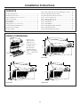
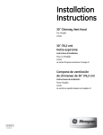
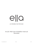
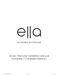
Installation
Instructions
If you have questions, call 800-GE-CARES or visit our website at: www.monogram.com
30", 36" and 48"
Restaurant Style
Vent Hoods
Models:
ZV48R
ZV36R
ZV30R
Monogram.
®
We bring good things to life.
1
Installation Instructions
BEFORE YOU BEGIN
WARNING:
Read these instructions completely and carefully.
TO REDUCE THE RISK OF FIRE, ELECTRICAL
SHOCK OR INJURY TO PERSONS, OBSERVE THE
FOLLOWING:
A. Use this unit only in the manner intended by the
manufacturer. If you have any questions, contact the
manufacturer.
B. Before servicing or cleaning unit, switch power off at
the service panel and lock service panel to prevent
power from being switched on accidentally. If the
service panel cannot be locked, fasten a tag or
prominent warning label to the panel.
• IMPORTANT - Save these instructions for
local inspector’s use.
• IMPORTANT - Observe all governing codes
and ordinances.
• Note to Installer - Be sure to leave these instructions
with the Consumer.
• Note to Consumer - Keep these instructions for
future reference.
• Skill Level – Installation of this vent hood requires
basic mechanical and electrical skills.
• Completion time – 1 to 3 hours.
• Proper installation is the responsibility of the installer.
• Product failure due to improper installation is not
covered under the Warranty.
ADVERTISSEMENT
POUR RÉDUIRE LE RISQUE D’INCENDIE, DE
CHOC ÉLECTRIQUE OU DE BLESSURES, IL FAUT
OBSERVER LES REGLES SUIVANTES:
A. Utiliser cet appareil uniquement de la maniére
prévue par le fabricant. En cas de question, consulter
le fabricant.
B. Avant toute intervention ou nettoyage, couper
l’alimentation électrique au disjoncteur et
verrouiller le panneau du disjoncteur pour éviter la
mise sous tension accidentelle. S’il n’est pas possible
de verrouiller le panneau du disconcteur, attacher
un placard ou une étiquette trés visible au panneau.
• For general ventilating use only. Do not use to exhaust
hazardous or explosive materials or vapors.
• Structural framing, installation work and electrical
wiring must be done by qualified person(s). In
accordance with all applicable codes and standards
including fire-rated construction.
• Sufficient air is needed for proper combustion and
exhausting of gases through the flue (chimney) of fuel
burning equipment to prevent back drafting. Follow
the heating equipment manufacturer’s guideline and
safety standards such as those published by the
National Fire Protection Association (NFPA), and the
American Society for Heating, Refrigeration and Air
Conditioning Engineers (ASHRAE), and the local
code authorities.
• Local codes vary. Installation electrical connections
and grounding must comply with applicable codes. In
the absence of local codes, the vent should be installed in accordance with National Electrical Code
ANSI/NFPA 70-1990 or latest edition.
CAUTION:
Due to the weight and size of these vent hoods and to
reduce the risk of personal injury or damage to the
product, TWO PEOPLE ARE REQUIRED FOR
PROPER INSTALLATION.
PRUDENCE
À cause du poids et de la taille de ces hottes et pour
reduire le risque de blessures et de dommages, IL FAUT
DEUX PERSONNES POUR FAIRE L’INSTALLATION
CORRECTEMENT.
WARNING:
To reduce the risk of fire or electrical shock, do not use
this range hood with any external solid-state speed
control device. Any such alteration from original factory
wiring could result in damage to the unit and/or create
an electrical safety hazard.
ADVERTISSEMENT
Pour réduire le risque d’incendie ou de choc électrique,
il ne faut pas utiliser cette hotte avec un régulateur de
vitesse électronique externe. Toute modification de ce
type du branchement d’usine peute endommager
l’appareil ou créer un risque de choc électrique.
CAUTION: To reduce risk of fire and to
properly exhaust air, be sure to duct air outside – Do
not vent exhaust air into spaces within walls or ceilings
or into attics, crawl spaces, or garages.
TO REDUCE THE RISK OF FIRE, USE ONLY METAL
DUCTWORK.
PRUDENCEIl faut prendre soin d’installer
un conduit vers l’extérieur pour réduire le risque
d’incendie et pouvoir évacuer l’air correctement. Il ne
faut pas évacuer l’air correctement. Il ne faut pas
évacuer l’air dans l’espace entre les parois d’un mur, un
plafond ou un grenier, un espace sanitaire ou un
garage.
2
Installation Instructions
CONTENTS
Step 1, Determine Ductwork and Wiring Locations .... 10
Step 2A, Install Hood Onto Wall ................................... 11
Step 2B, Install Hood Beneath Soffit ............................ 12
Step 3, Connect Ductwork ............................................. 13
Step 4, Connect Electrical .............................................. 13
Step 5, Install Duct Covers ............................................. 13
Step 6, Install Motor ....................................................... 13
Step 7, Install Filters ....................................................... 14
Step 8, Install Backguard and Shelf ............................... 14
Step 9, Install Shelf Only ................................................ 15
Step 10, Install Implement Rods ................................... 15
Product Dimensions ......................................................... 3
Installation Clearances ..................................................... 4
Optional Duct Cover Accessories .................................... 4
Advance Planning ............................................................. 5
Power Supply .................................................................... 5
Duct Fittings ...................................................................... 6
Using Duct Cover Accessories .......................................... 7
Tools and Materials Required .......................................... 8
Remove the packaging ..................................................... 8
Parts Provided ................................................................... 9
PRODUCT DIMENSIONS
12"
Warming
Shelf
ard
Backgu
Each hood is
shipped with a
stainless steel
backguard and a
warming shelf.
Hoods may be
installed with the
shelf or backguard
alone, or with both
as shown.
47-15/16"
10"
22-1/2"
47-15/16"
25"
Model ZV48R
12"
35-15/16"
29-15/16"
12"
10"
10"
22-1/2"
22-1/2"
25"
35-15/16"
25"
Model ZV36R
Model ZV30R
3
29-15/16"
Advance Planning
INSTALLATION CLEARANCES
OPTIONAL DUCT COVER
ACCESSORIES
These vent hoods are designed to be installed onto a
wall or beneath a soffit or cabinet.
Installation with Warming Shelf
• Hoods must be installed 32" Min., 38" Max over any
type cooking surface when warming shelf is used.
Installation without Warming Shelf
• Install these hoods 30" Min. to 36" Max. above the
cooking surface when installed over any professional
style cooktop or range.
• These hoods may be installed 24" min. above a gas or
electric drop-in style cooktop.
Decorative duct covers are available in 6" and 12"
heights. Duct covers may be stacked, in various
combinations, to conceal the ductwork running from
the top of the hood to the ceiling.
• Before you begin, you should determine the installation height of the hood and order the correct size
duct cover. The duct covers should be ordered at the
same time as the vent hood and be on site before
installation. Order the duct cover corresponding to
your model.
Note: Clearances may vary due to type of cooking product and
local codes. Check with local inspectors to be sure standard is
applicable.
6" Duct Cover
12" Duct Cover
Soffit Installation
SOFFIT
SOFFIT
30" Min.
36" Max.
Install these hoods 30" Min. to
36" Max. over a professional
style cooktop or range.
32" Min.
38" Max.
Allow 32" min. and 38" max.
clearance above any cooking
surface when installed with shelf.
In this installation the ductwork running from the top
of the hood will be concealed in the soffit or upper
cabinetry.
Wall Mount Installation
30" Min.
36" Max.
Install these hoods 30" Min. to
36" Max. over a professional
style cooktop or range.
32" Min.
38" Max.
Allow 32" min. and 38" max.
clearance above any cooking
surface when installed with shelf.
For this installation, a decorative duct cover is available to conceal the ductwork running from the top of
the hood. Use of the duct cover requires special
consideration to the installation height above the
countertop.
4
6" Duct Covers
Hood Model
ZV48R
ZV36R
ZV30R
6” Duct Cover
ZX48DC6
ZX36DC6
ZX36DC6
Dimensions
6"H x 19-11/16"W x 11-7/8"D
6"H x 15-3/4"W x 11-7/8"D
6"H x 15-3/4"W x 11-7/8"D
12" Duct Covers
Hood Model
ZV48R
ZV36R
ZV30R
12” Duct Cover
ZX48DC12
ZX36DC12
ZX36DC12
Dimensions
12"H x 19-11/16"W x 11-7/8"D
12"H x 15-3/4"W x 11-7/8"D
12"H x 15-3/4"W x 11-7/8"D
Advance Planning
ADVANCE PLANNING
POWER SUPPLY
Ductwork Planning
• These vent hoods are equipped for 10" round
ductwork. For best performance, use 10" round
ductwork on the 48" wide hoods. 30" and 36" hoods
may be transitioned to 8" round.
• This hood may be vented vertically through upper
cabinets, soffit or ceiling. A duct transition piece is
supplied for vertical exhaust. Use locally supplied
elbows to vent horizontally through the rear wall.
• Determine the exact location of the vent hood.
• Plan the route for venting exhaust to the outdoors.
• Use the shortest and straightest duct route possible.
For satisfactory performance, duct run should
not exceed 150 ft. equivalent length for any duct
configurations.
• Refer to “Duct Fittings” chart to compute the maximum permissible length for duct runs to the outdoors.
• Use metal ductwork only.
• Install a wall cap or roof cap with damper at the
exterior opening. Order the wall or roof cap and any
transition needed in advance.
Wall Framing for Adequate Support
• These vent hoods are heavy. Adequate structural
support must be provided. Hoods must be secured to
vertical studs in the wall.
• It is strongly recommend that the vent hood with
duct cover be on site before final framing and wall
finishing. This will also help to accurately locate the
ductwork and electrical service.
Decorative Duct Covers:
Decorative duct covers, 6" and 12" high, are available to
fit all models. The duct cover conceals the ductwork
running from the top of the hood to the ceiling or
soffit. Stack one or more duct covers over the top of
the hood to reach your ceiling height.
IMPORTANT - (Please read carefully)
WARNING:
FOR PERSONAL SAFETY, THIS APPLIANCE MUST
BE PROPERLY GROUNDED.
ATTENTION – POUR DES RAISONS
DE SÉCURITÉ, CET APPAREIL DOIT ÊTRE
CORRECTEMENT MIS À LA TERRE.
Remove house fuse or open circuit breaker before
beginning installation.
Do not use an extension cord or adapter plug with this
appliance. Follow National electrical codes or prevailing local codes and ordinances.
Electrical supply
These vent hoods must be supplied with 120V, 60Hz,
and connected to an individual, properly grounded
branch circuit, and protected by a 15 or 20 amp circuit
breaker or time delay fuse.
• Wiring must be 2 wire with ground.
• If the electrical supply does not meet the above
requirements, call a licensed electrician before
proceeding.
• Route house wiring as close to the installation
location as possible on the back wall or ceiling.
• Connect the wiring to the house wiring in accordance with local codes.
Grounding instructions
The grounding conductor must be connected to a
ground metal, permanent wiring system, or an equipment-grounding terminal or lead on the hood.
WARNING: The improper connection of
the equipment-grounding conductor can result in a
risk of electric shock. Check with a qualified electrician
or service representative if you are in doubt whether
the appliance is properly grounded.
ADVERTISSEMENT
Le mauvais branchement du fil de mise à la terre peut
causer un choc électrique. En cas de doute, consulter
un électricien qualifié ou un technicien pour
déterminer si l’appareil est à la terre.
5
Advance Planning
DUCT FITTINGS
Use this chart to compute maximum
permissable lengths for duct runs to
outdoors.
Note: Do not exceed maximum permissable
equivalent lengths!
Equivalent
Length*
Duct Piece
10" round
to 8" round
Round,
straight
Quantity
Used
10 ft.
1 ft.
(per foot
length)
Maximum recommended duct
length for these hoods: 150 feet
3-1/4" x 24"
straight
1 ft.
(per foot
length)
Flexible ducting:
If flexible metal ducting is used, all
the equivalent feet values in the table
should be doubled. The flexible
metal duct should be straight and
smooth and extended as much as
possible.
90° elbow
15 ft.
45° elbow
9 ft.
3-1⁄4" x 12" or
3-1/4" x 24"
90° elbow
15 ft.
3-1/4" x 24"
45° elbow
9 ft.
3-1/4" x 24"
90° flat elbow
20 ft.
10" round to
3-1/4" x 24" transition
1 ft.
3-1/4" x 24" to 10"
round transition
5 ft.
10" round
to 3-1/4" x 24"
transition 90° elbow
5 ft.
Do NOT use flexible plastic ducting.
Note: Any home ventilation system, such as a
ventilation hood, may interrupt the proper flow of
combustion air and exhaust required by fireplaces,
gas furnaces, gas water heaters and other naturally
vented systems. To minimize the chance of interruption
of such naturally vented systems, follow the heating
equipment manufacturer’s guidelines and safety
standards such as those published by NFPA and ASHRAE.
Hoods Are Equipped
For 10" Round Duct
*Hoods are supplied with a 10"
round transition. A locally
supplied transition is required
for other sizes.
Note: Outlet on top of hood is
8-1/8" x 8".
* Actual length of straight duct plus duct fitting
equivalent. Equivalent length of duct pieces
are based on actual tests conducted by GE
Evaluation Engineering and reflect requirements for good venting performance with
any ventilation hood.
3-1/4" x 24" to 10"
round transition 90° elbow 15 ft.
Round
wall cap
with damper
30 ft.
3-1/4" x 24" wall cap
with damper
30 ft.
Round
roof cap
26 ft.
Round
roof vent
24 ft.
Total Duct Run
6
Total
Length
Advance Planning
USING DUCT COVER ACCESSORIES
We recommend that the vent hood and decorative
duct cover (if used) be on site before final framing and
wall finishing. This will help to accurately locate studs,
ductwork and electrical service.
• Read these examples carefully to determine the need
for one or more 6" or 12" duct covers.
To avoid unsightly gaps, plan the hood installation
height for duct cover use. Use the following formula
to calculate the need for one or more duct covers
and to ensure a trouble free installation.
Ceiling Height
B
10" Hood
Height
A = Countertop to ceiling height.
B = Gap at the top of the hood to the ceiling.
C = Hood installation height - Plus 10" hood height.
A
C
NOTE: Dim. C should be between 40" and 46" (for a
30" to 36" installation height). Raise or lower the hood
installation height to allow use of one or more 6" and
12" duct covers.
A-B=C
INSTALLATION EXAMPLES
24"
12"
38"
32"
8 ft. ceilings: When the hood is installed
32" above the cooking surface and there is
no soffit or upper cabinetry, order one 12"
and one 6" duct cover accessory.
42"
32"
9 ft. ceilings: When the hood is installed 38"
above the cooking surface, order two 12" duct
cover accessories.
7
10 ft. ceilings: When the hood is installed
36" above the cooking surface, order three
12" and one 6" duct cover accessories.
Installation Preparation
TOOLS AND MATERIALS REQUIRED
(NOT SUPPLIED)
1/4" pivoting
hex socket
Duct tape
Hammer
Key Hole Saw
Wire cutter/stripper
Pencil and tape measure
Safety glasses
Wire nuts
Spirit level
Flashlight
Pliers
Electric or battery operated drill
and 1/8", 3/8" bits
10" round metal
duct, length to
suit installation.
Phillips and flat
blade
screwdrdivers
Strain relief for
junction cover.
Step ladder
Metal Snips
120V 60Hz. 15 or 20 Amp,
2-wire with ground. Properly
grounded branch circuit.
Saber saw
or Sawsall
REMOVE THE PACKAGING
• Remove packages from the “V” shaped cardboard
section. Remove shipping pads.
• Lift the hood out of the box.
• Grease filters must be removed. Grasp the latch, pull
the filter up and lift out.
IMPORTANT: Lift the hood by grasping
the outside edges of the exhaust opening on the top.
Duct
Transition
Wood
Mounting
Support
Hood
Parts
• Lift to remove the grease trays. Set grease filters and
trays aside for later installation. DO NOT DISCARD.
Motor
Mounted
on Skid
Shipping Carton
• The vent hood motor is shipped secured to the skid with
4 screws. Locate and remove 2 screws on each side of the
motor. Discard the shipping skid and screws.
• From the inside of the hood, loosen (do not remove)
the 2 screws holding the wood mounting support to
the back of the hood. Remove and set aside the
mounting support with screws for later installation.
DO NOT DISCARD.
• Remove tape and packing material from the hood and
all supplied parts.
8
Installation Preparation
PARTS PROVIDED
Locate the parts packed with the hood.
Duct Transition
with Damper
Wood Support
with Original Screws
2 Stainless Steel Grease Filters
(3 filters with 48" models)
Heat Lamp
(2 with 48" models)
2 Implement Rods and 4 Stand-offs
Allen Wrench
For Implement Rods
Backguard
Grease Tray
Warming Shelf
HARDWARE
PACKAGE
4 Phillips head screws to
secure the duct transition to
the hood outlet on the top.
Locate and check
contents. Screws
shown actual size.
4 screws to secure the wood
support to the wall
POZIDRIV 3
2 flat washers
for wall anchors
6 (3/16") hollow wall anchors
with screws use 2 to secure
hood to the wall at the bottom.
Use 4 to secure backguard
and shelf.
10 Phillips head screws.
Use 6 to secure hood to the
wood support. (2 are
secured to wood support)
Use 2 to secure 30" and 36"
backguards to wall. Use 4 to
secure a 48" backguard.
2 Phillips head machine
screws to secure shelf to
bottom of hood.
2 shoulder screws
to secure shelf to
bottom of hood.
9
1 safety screw and lock
washer, to secure the
blower (screw is marked
with red paint).
Installation Instructions
STEP 1 DETERMINE HOOD, DUCTWORK AND WIRING LOCATIONS
• Use a level to draw the cooktop centerline location.
Draw the line to ceiling height.
• Measure desired distance from the bottom of the
hood to the cooking surface.
Top of Hood
20"
Note: If you are installing the hood with duct covers, be sure to read
“Using Duct Cover Accessories” page 7. Exact installation height
may be determined by use of one or more duct covers.
Wood
Support
22-1/2"
Bottom of Hood
• Determine bottom
of hood location
(Dimension A) by
subtracting 12-1/2"
from the desired
installation height.
*House Wiring
Location
Dimension A
Cooking Surface
Installation
Height
Dim. A
*See recessed
location below.
FOR VERTICAL (Straight Up) DUCTING:
• Use a level to draw a centerline from the bottom of the
hood to ceiling or soffit.
• If venting out the ceiling, extend the centerline
forward on the ceiling or soffit.
• Locate the centerline of a 10-1/2" hole on the ceiling
or soffit by measuring 6" from the wall.
• Use a level to draw a straight horizontal pencil line
indicating the bottom of the hood.
• From the line indicating the bottom of the hood,
measure 20" up and draw another line for the location of the wood support. See illustration.
FOR DUCTING THROUGH REAR WALL:
• Measure the supplied duct transition with any straight
run length of duct used, plus 90° elbow height. Draw
horizontal line on the wall intersecting the centerline.
House Wiring Location:
• The junction box is fastened to the back of the hood
on the right side.
18-1/16" for 48" Models
12-1/16" for 36" Models
9-1/16" for 30" Models
6-1/2"
14-1/4"
Electrical
Area
14" for 48" Models
8" for 36" Models
5" for 30" Models
Alternate Knockout Locations (for soffit installation)
If the installation requires, the junction box can be
relocated from the back to the top of the hood. Remove
3 screws, align box to top knockout and secure with
original screws.
• Remove junction box cover and knockout. Install strain
relief.
• The recessed back side of the hood provides a large
area for the house wiring to exit the wall and be
routed to the rear knockout and junction box.
• The location for the house wiring depends on the
installation height of the hood and the width of the
hood. See shaded “Electrical Area” for locations.
• Remove junction box cover and knockout. Install
strain relief.
10
Installation Instructions
STEP 2A INSTALL HOOD ONTO WALL
IMPORTANT: Framing must be capable of
supporting up to 150 lbs.
Install Transition Onto Top of Hood
SKIP THIS STEP IF INSTALLING BENEATH A SOFFIT
OR CABINET, GO TO STEP 2B.
• Locate at least 2 vertical studs at the wood support.
• Center the supplied wood support, left to right and
below the 20" marked line.
Duct
Transition
IMPORTANT: Remove
shipping tape from
damper and check that
damper moves freely.
Bottom
of
Hood
Wood
Support
20"
of
Top od
Ho
• Place the duct transition piece over the hood exhaust
and secure with 4 screws provided.
• Use duct tape to seal the connection. Check to be sure
the damper moves freely.
Hang Hood On Wood Support
• Lift the hood and hold close to the installation location.
Route house wiring through the knockout and into the
junction box.
• Place the hood over the wood support. Be sure the
mounting screws engage the keyhole slots in the back of
the hood.
• Check to be sure the hood is level and centered.
Centerline of
Installation
Space
• Secure the wood support to 2 or more vertical studs,
using at least 2 of the 4 supplied long screws.
IMPORTANT: Screws must penetrate at least 1-1/2"
into vertical studs. Countersink screws into support.
Note: The mounting
screws must remain in
their original shipping
location. These screws
are positioned to engage
the keyhole slots in the
back of the hood.
Bottom
Mounting
Holes
30"
to
36"
Centerline of
Installation
Space
Original Mounting
Screws as Shipped
Test Duct Cover Fit
• Place duct cover(s) over the top of the hood to check
for gaps. Adjust the hood up or down if necessary.
1/4"
Gap
Install Bottom Mounting Screws
• Drill 1/8" pilot holes into the two bottom mounting
holes. Enlarge the holes if they did not enter studs to
3/8". Insert anchors for wall fasteners into bottom
holes. Remove anchor screws and add flat washers
provided. Drive screws into anchors and tighten.
• Install 4 additional screws through the inside back of
the hood and into the wood support.
• Adjust depth of original mounting screws in wood
support until they protrude 1/4" forward. This 1/4"
gap will provide clearance to hang the hood.
11
Installation Instructions
STEP 2B Alternate Mounting Method
INSTALL HOOD TO SOFFIT OR BENEATH CABINETS
SKIP THIS STEP IF USING WALL MOUNTING
METHOD
When necessary, the hood may be installed so that it is
supported by the soffit.
• The soffit should be constructed with 2 x 4’s.
• Determine the installation location on the wall.
• Continue the centerline forward on the bottom of
the cabinet or soffit.
• The opening above the hood should allow for the 10"
round duct and clearance to slide the hood back
against the wall.
IMPORTANT: Soffit framing must be capable
of supporting up to 150 lbs.
Install Transition Onto Top of Hood
Duct
Transition
IMPORTANT: Remove
shipping tape from
damper and check that
damper moves freely.
Requires 10-1/2" Min.
Opening For Ductwork
and Hood Installation
of
Top od
o
H
• Place the transition piece over the hood exhaust and
secure with 4 screws provided.
• Use duct tape to seal the connection. Check to be sure
the damper moves freely.
Mount Hood onto Soffit or Cabinet
Note: If mounting to the underside of a cabinet with a
recessed bottom, install shims to fill the gap.
A
Soffit
A
• The 2 x 4 studs must be located as shown in the chart,
Dim. A. to accept mounting screws.
ZV48R
ZV36R
“A”
Centerline to Stud
and Keyhole Slots
23-9/16"
17-9/16"
“B”
Hood Width
At the Top
47-15/16"
35-15/16"
ZV30R
14-9/16"
29-15/16"
2"
Engage Top
Keyhole Slots
Push Back
to Wall
Top View
Front of Hood
A
8"
C
6"
2-9/16"
Add Shims
If Bottom
Is Recessed
Back
Wall
• Drive mounting screws into the studs until they
protrude 1/4". The 1/4" gap will provide clearance to
engage the keyhole slots in the top of the hood.
• Lift hood to installation position. Locate house wiring
and route through the knockout (from the back or
top of the hood).
• Lift hood onto mounting screws. Slide back against
the rear wall.
• Tighten mounting screws.
8-1/8"
7-1/2"
1/4" Gap
B
IMPORTANT: For additional support and to minimize vibration during operation, the hood must be
secured to the back wall. Use wall anchors to fasten
bottom back of hood to the wall.
Back of Hood
• Drill 1/8" pilot holes into the studs at the locations
shown in the top view illustration.
12
Installation Instructions
STEP 3 CONNECT DUCTWORK
STEP 5 INSTALL DUCT COVERS
• Install ductwork, making connections in direction of
airflow as illustrated.
• Secure joints in ductwork with sheetmetal screws.
• Wrap all duct joints with
duct tape for an airtight seal.
• Use duct tape to seal the
flange connection.
Air Flow
Reach inside the
Duct Tape
hood and push
Over Seam
Screw
the damper up
and Screw
to be sure it
moves freely.
Note: For easier handling, remove cardboard insert
after film is peeled off.
Remove protective film from duct covers. If more than
one duct cover is used, secure each piece together with
screws provided.
• Place the duct cover(s) on top of the hood.
• From inside the hood, secure the duct cover to the
top with the small Phillips head screws supplied with
the covers.
STEP 6 INSTALL MOTOR
Duct Tape
Over Transition
Outlet
STEP 4 CONNECT ELECTRICAL
Attachment
Slot
Verify that power is turned off at the source.
WARNING: If house wiring is not 2-wire
• From the inside of the hood, slip motor into the
attachment slot on the left.
• Rotate motor upwards until it snaps into the spring
clip on the right.
• Secure the motor to the hood with the machine
screw and lock washer. (Screw is marked with red
paint.)
• Plug connector into the motor.
with a ground wire, a ground must be provided by the
installer. When house wiring is aluminum, be sure to
use U.L. approved anti-oxidant compound and aluminum-to-copper connectors.
ATTENTION – Si le câblage de la
maison n’est pas du type à deux fils avec un fil de
terre, l’installateur doit fournir un circuit de terre.
Quand les fils de la maison sont en aluminium, il
prendre soin d’utiliser de la pâte antioxidation
approuvée par UL et des connecteurs pour
l’aluminium-cuivre.
A Remove
Junction Box
Cover
Spring
Clip
Attachment
Screw
Top
B Insert Power
Conduit Thru
Strain Relief
and Tighten
Ground
White
Black
IMPORTANT: Connector ends
are designed to mate only
one way. Match flat and
round connectors as shown.
C Use UL Listed
Wire Nuts
• Use wire nuts to connect incoming ground to green,
white to white and black to black.
• Push wires into junction box and replace cover. Be
sure wires are not pinched.
13
Spring
Clip
Installation Instructions
STEP 7 INSTALL FILTERS
• Insert the filter into the opening and drop into the
bottom. Raise filter to the top and lock into place.
• Drop grease tray into the hood. The rear tabs should
engage the slots in the hood track.
• To remove the filters, grasp the latch, pull the filter
up and lift out.
STEP 8 INSTALL BACKGUARD AND SHELF
INSTALL BACKGUARD:
• Remove packaging.
• Place backguard against the bottom of the hood to
use as a template. Mark upper screw locations “A”
and “B”
• Remove backguard.
• Drill four 1/8" pilot holes at screw locations “A”
and “B”.
• If drill did not enter studs, enlarge holes to 3/8".
• Insert wall anchors into the enlarged holes. Remove
screws from wall anchors.
• Align and secure backguard to wall using 2 wall
anchor screws or wood screws in locations “A”.
• For 30" and 36" models, install 2 screws through
hole locations “C” at the bottom of the backguard.
For 48" models, install 4 screws.
This hood can be installed with the warming shelf and backguard together or with
the warming shelf or backguard alone.
INSTALL SHELF OVER BACKGUARD:
• Install two shoulder screws into holes “D” in the
bottom of hood flange leaving 1/8" gap.
• Remove shelf packaging and protective film.
• Engage shoulder screws into the keyhole slots in the
top of the shelf. Slide shelf towards the left to lock
into place.
• Install two 3/4" long machine screws through the
bottom of the shelf into the bottom hood flange,
location “E”.
• Install anchor screws through the shelf and into the
wall holes “B”.
• Remove all protective film.
1/8"
Gap
E
D
A
A
Mounting
B
Holes for
UARD
BACKG
Backguard (A, C)
and Shelf (B)
D
E
B
B
C
• If installing the backguard alone, without the
shelf, drive screws in all locations shown.
14
B
Installation Instructions
STEP 10 INSTALL IMPLEMENT
RODS
STEP 9 INSTALL SHELF “ONLY”
• Remove shelf packaging and protective film.
• If installing the shelf alone, without the backguard,
place shelf against the bottom of the hood and mark
screw hole locations “B” on the wall.
• Drill two 1/8" pilot holes.
• If drill did not enter studs, enlarge holes to 3/8".
• Insert wall anchors into enlarged holes. Remove
screws from wall anchors.
• Install two shoulder screws into holes “D” in the
bottom of hood flange leaving 1/8" gap.
• Engage shoulder screws into the keyhole slots in the
top of the shelf. Slide shelf towards the left to lock
into place.
• Install two 3/4" long machine screws through the
bottom of the shelf into the bottom hood flange,
location “E”.
Screw
Stand-offs
Into
Hood
Use Allen
Wrench to
Secure Rod
to Stand-offs
• Use a flat blade screwdriver to install stand-offs into
the bottom of the hood.
• Align implement rod to stand-offs with the screw hole
towards the inside of the hood. Secure the rod to the
stand-offs with the supplied Allen wrench.
• Follow the same procedure on the opposite side.
1/8"
Gap
E
D
D
E
B
FINALIZE INSTALLATION
• Install the supplied infrared bulb(s).
• See the Owner’s Manual for instructions to test
operation.
B
Mounting
Holes
for Shelf (B)
15
Note: While performing installations described in this book,
safety glasses or goggles should be worn.
For Monogram® local service in your area, call
1-800-444-1845.
Note: Product improvement is a continuing endeavor at
General Electric. Therefore, materials, appearance and
specifications are subject to change without notice.
Monogram.
®
We bring good things to life.
General Electric Company
Louisville, KY 40225
Pub. No. 49-80152-2
Dwg. No. 164D4290P109
(N.D. 762) 5/03
Printed in Italy
16