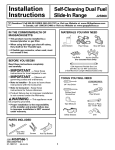
1
Installation
Instructions
Self-Cleaning Radiant Trivection™
Electric Slide-In Range JS998
Questions? Call 800.GE.CARES (800.432.2737) or Visit our Website at: www.GEAppliances.com
BEFORE YOU BEGIN
FOR YOUR SAFETY: (cont.)
Read these instructions completely
and carefully.
• To reduce the risk of burns or fire when
reaching over hot surface elements, cabinet
storage space above the cooktop should be
avoided. If cabinet storage space is to be
provided above the cooktop, the risk can
be reduced by installing a range hood that
protrudes at least 5” beyond the front of
the cabinets. Cabinets installed above a
cooktop must be no deeper than 13”
.
• Be sure your appliance is properly installed
and grounded by a qualified technician.
• To prevent damage to the door and to
prevent excessive microwave leakage,
do NOT remove the door on the oven.
•
IMPORTANT
•
IMPORTANT
•
•
•
•
•
•
— Save these
instructions for local inspector’s use.
— Observe all
governing codes and ordinances.
Note to Installer – Be sure to leave these
instructions with the Consumer.
Note to Consumer – Keep these
instructions for future reference.
Skill level – Installation of this appliance
requires basic mechanical and advanced
electrical skills.
Completion time – 1 to 3 hours
Proper installation is the responsibility of
the installer.
Product failure due to improper installation
is not covered under the Warranty.
ANTI-TIP DEVICE
WARNING
— To reduce the risk
of tipping, the appliance must be secured by
properly installed Anti-Tip bracket packed
with this appliance.
• If the Anti-Tip device supplied with the
range does not fit this application, use the
universal Anti-Tip device WB2X7909.
WARNING
— This appliance must
be properly grounded.
FOR YOUR SAFETY:
WARNING
WARNING
— For personal safety,
do not use an extension cord with this
appliance. Remove house fuse or open circuit
breaker before beginning installation. Failure
to do so could result in serious injury or
even death.
• All rough-in and spacing dimensions
must be met for safe use of your range.
Electricity to the range can be disconnected
at the outlet without moving the range if
the outlet is in the preferred location
(remove lower drawer).
229C4053P547-4
31-10558-4
05-04 JR
—
• All ranges can tip
• Injury to persons could result
• Install Anti-Tip bracket packed
with range
• See Installation Instructions
• If you pull the range out and away from the
wall for any reason, make sure the Anti-Tip
bracket is engaged when the range is
pushed back against the wall.
1
Installation Instructions
PREPARE TO INSTALL THE RANGE
TOOLS YOU WILL NEED
1/8” Drill Bit and
Electric or Hand Drill
(Extension May Be
Required)
MATERIALS NEEDED
Safety Glasses
Lag Bolts
Anchor Sleeves
(For Concrete Floors Only)
Tape Measure
Adjustable Wrench
(for 1-7/16″ Nut)
Pliers
(UL Approved 40 or 50 AMP)
Pencil
4-Wire Cord
4‘ Long
with Strain Relief
Level
3-Wire Cord
4‘ Long
with Strain Relief
PARTS INCLUDED
1/4” Nut Driver
Straight Edge
or Square
Hand or Saber Saw
OR
Rear Filler,
2 Screws
Gloves
2
Screws
Anti-Tip Bracket
Installation Instructions
1 PRE-INSTALLATION CHECKLIST
1 PRE-INSTALLATION CHECKLIST
(cont.)
INSPECT INSTALLATION LOCATION
• Counter opening extends to the wall:
Maintop Filler (supplied with the range).
(See Alternate Construction section for
Installation Instructions) or Backguard Kit
(Kit JXS37XX) (See Alternate Construction
section)
• Do not remove the protective channel from
the sides of the glass cooktop until later
in the installation.
Protective channel
• Counter height greater than 36-3/4″:
Lower Trim Slide-In Kit (Kit JXS56XX)
• One side is not enclosed by a cabinet:
Bodyside Kit (Kit JXS76XX)
• Island Installation:
To provide an optimum installation, the
top surface of the countertop must be level
and flat (lie on the same plane) around the
3 sides that are adjacent to the range
cooktop. Proper adjustments to make the
top flat should be made or gaps between
the countertop and range cooktop may
occur. Forcing the cooktop to fit may cause
excessive gaps and could break the glass
and void the warranty.
• Carefully, tilt the range to access the range
leveling legs. Use an adjustable wrench to
screw leveling legs out so that glass support
flanges clear the top of the countertop.
• Remove packing materials. Remove plastic
on trim and panel, and all tape around the
range.
To obtain kits, visit the GE Website or call
the GE Answer Center (800.432.2737), or
contact your dealer.
NOTE: To prevent damage to the door and
to prevent excessive microwave leakage,
do NOT remove the range door. DO NOT LIFT
THE RANGE BY THE HANDLE!
• Move range indoors in front of cabinet
opening.
(Do not use hand trucks when moving the
unpackaged range. Cooktop glass may be
broken.)
STORAGE DRAWER REMOVAL
• Pull the drawer out until it stops.
• Lift the front of the drawer until the stops
clear the guides.
• Protect the kitchen floor! Flatten and place
a piece of the shipping carton in front of the
installation location to protect the flooring.
Rail
Guide
Stop
Stop
• Pull forward and remove the drawer.
3
Installation Instructions
PREPARE TO INSTALL THE RANGE
(cont.)
2 PRE-INSTALLATION CUTOUT
AND REQUIRED CLEARANCES
NOTE: The oven below the cooktop meets
UL requirements for 0″ clearance to back and
side walls and cabinets.
Wall coverings, counters and cabinets around
the range must withstand heat (up to 194°F)
generated by the range.
If a 30″ clearance between the cooking surface
and the overhead combustible materials or
metal cabinets cannot be maintained, a
minimum clearance of 24″ is required and
the underside of the cabinets above the
cooktop must be protected with not less than
1/4″ insulating millboard covered with sheet
metal not less than 0.0122″ thick.
4
Installation Instructions
2 PRE-INSTALLATION CUTOUT
AND REQUIRED CLEARANCES (cont.)
STANDARD INSTALLATION
Wall
1/4″ Min.
Flat
23-3/16″
Flat
Area
25″
Typically
R
9/16″ Min.
Flat
9/16″ Min.
Flat
36″
1/4″
29-15/16″–30-1/16″
Smooth Cut
• Center the 30″ wide opening over the adjacent
cabinets and mark with a straight edge.
If the construction of your cabinet cannot
provide a 1/4″ flat area at the back of the
countertop opening, consider changing the
countertop to accommodate this dimension.
See Alternate Construction section. If the area
is not flat, excess tension may be applied to
the glass cooktop, causing breakage and
voiding the warranty.
If the existing cabinet opening is approximately
30-3/8,″ the Vertical Side Trim Kit (JXS86XX)
should be used to cover gaps between range
sides and cabinet. Refer to the kit instructions
for installation details.
When installing the range at the end of a
cabinet section that will expose the unfinished
side of the range, use Body Side Kit (JXS76XX).
Refer to the kit instructions for installation details.
If countertop height is between 36-1/2″ and 38,″
a lower trim kit (JXS56XX) is recommended.
Refer to the kit instructions for installation details.
• Using a straight edge, mark the back line at
23-3/16″ from the front edge of the counter.
• Be careful not to damage the adjacent
cabinets while cutting the countertop. Use a
hand or saber saw to make straight smooth
cuts.
• Remove countertop raised edge,
if incorporated.
9/16″
Shave raised edge
to clear 31-1/8″
wide control panel
Flat & Level
With Back &
Opposite Side
6"
3/1
23-
30"
"
1/4
1"
9
Ea /16"
ch
Sid
e
38"
to
4" or
/
3
36- o Flo
t
5
Installation Instructions
ELECTRICAL CONNECTIONS
ELECTRICAL REQUIREMENTS
Use only a 3-conductor or a 4-conductor
UL-listed range cord. These cords may be
provided with ring terminals on wire and a
strain relief device.
CAUTION:
For personal safety,
do not use an extension cord with this
appliance. Remove house fuse or open
circuit breaker before beginning
installation.
A range cord rated at 40 amps with 125/250
minimum volt range is required. A 50 amp
range cord is not recommended but if used, it
should be marked for use with nominal 1-3/8″
diameter connection openings. Care should
be taken to center the cable and strain relief
within the knockout hole to keep the edge
from damaging the cable.
This appliance must be supplied with the
proper voltage and frequency, and connected
to an individual properly grounded branch
circuit, protected by a circuit breaker or fuse
having amperage as specified on the rating
plate. The rating plate is located on the
oven frame.
• Because range terminals are not accessible
after range is in position, flexible service
conduit or cord must be used.
We recommend you have the electrical wiring
and hookup of your range connected by a
qualified electrician. After installation, have
the electrician show you where your main
range disconnect is located.
NOTE: If conduit is being used, go to Step 3D
and then to Step 6 or 7.
• On some models, a filter capacitor may be
connected between the black and white
leads on the junction block.
Check with your local utilities for electrical
codes which apply in your area. Failure to
wire your range according to governing
codes could result in a hazardous condition.
If there are no local codes, your range must
be wired and fused to meet the requirements
of the National Electrical Code, ANSI/NFPA
No. 70—Latest Edition. You can get a copy
by writing:
National Fire Protection Association
Batterymarch Park
Quincy, MA 02269
Effective January 1, 1996, the National
Electrical Code requires that new construction
(not existing) utilize a 4-conductor connection
to an electric range.
ALL NEW CONSTRUCTIONS,
MOBILE HOMES AND
INSTALLATIONS WHERE
LOCAL CODES DO NOT
ALLOW GROUNDING
THROUGH NEUTRAL,
REQUIRE A 4-CONDUCTOR
UL-LISTED RANGE CORD.
When installing an electric range in new
construction, follow Steps 3 and 5 for 4-wire
connection.
You must use a 3-wire, single-phase A.C.
208Y/120 Volt or 240/120 Volt, 60 hertz
electrical system.
If the electrical service provided does not
meet the above specifications, have a
licensed electrician install an approved outlet.
6
Installation Instructions
3 POWER CORD AND STRAIN
RELIEF INSTALLATION
A
B
Remove the wire cover
(on the back of the
range) by removing 2
screws, using a 1/4″
nut driver.
Do not discard these
screws.
C
Wire
cover
Remove the knockout ring (1-3/8″)
located on bracket directly below the
terminal block. To remove the knockout,
use a pair of pliers to bend the knockout
ring away from the bracket and twist
until ring is removed.
For power cord installations only (see
the next step if using conduit), assemble
the strain relief in the hole. Insert the
power cord through the strain relief and
tighten. Allow enough slack to easily
attach the cord terminals to the terminal
block. If tabs are present at the end of
the winged strain relief, they can be
removed for better fit.
NOTE: Do not install the power cord
without a strain relief. The strain relief
bracket should be installed before
reinstalling the rear range wiring cover.
Terminal
block
Terminal
block
(appearance
may vary)
Strain relief
Power cord
Bracket
Skip to Step 4 or 5.
D
Knockout
ring removed
Knockout ring
in bracket
For conduit installations only, purchase
a squeeze connector matching the
diameter of your conduit and assemble
it in the hole. Insert the conduit through
the squeeze connector and tighten. Allow
enough slack to easily attach the wires
to the terminal block.
NOTE: Do not install the conduit without
a squeeze connector. The squeeze
connector should be installed before
reinstalling the rear range wiring cover.
Terminal
block
Squeeze
connector
Conduit
Bracket
Skip to Step 6 or 7.
7
Installation Instructions
ELECTRICAL CONNECTIONS
4 3-WIRE POWER CORD
INSTALLATION
(cont.)
5 4-WIRE POWER CORD
INSTALLATION
WARNING:
WARNING:
The neutral or
ground wire of the power cord must be
connected to the neutral terminal located
in the center of the terminal block. The
power leads must be connected to the
lower left and the lower right terminals
of the terminal block.
A
The neutral wire of
the supply circuit must be connected to
the neutral terminal located in the lower
center of the terminal block. The power
leads must be connected to the lower
left and the lower right terminals of the
terminal block. The 4th grounding lead
must be connected to the frame of the
range with the ground plate and the
ground screw.
Remove the 3 lower terminal screws from
the terminal block. Insert the 3 terminal
screws through each power cord terminal
ring and into the lower terminals of the
terminal block. Be certain that the center
wire (white/neutral) is connected to the
center lower position of the terminal
block. Tighten screws securely into the
terminal block.
DO NOT remove the ground strap
connection.
A
B
C
Terminal
block
(appearance
may vary)
D
Neutral
terminal
Ground
plate
Ground
strap
Remove the 3 lower terminal screws from
the terminal block. Remove the ground
screw and ground plate and retain them.
Cut and discard the ground strap. DO
NOT DISCARD ANY SCREWS.
Insert the one ground screw into the
power cord ground wire terminal ring,
through the ground plate and into the
frame of the range.
Insert the 3 terminal screws (removed
earlier) through each power cord terminal
ring and into the lower terminals of the
terminal block. Be certain that the center
wire (white/neutral) is connected to the
center lower position of the terminal
block. Tighten screws securely into the
terminal block.
Before
Terminal
block
Ground strap
or
Ground
strap
Power cord
After
B
Terminal
block
Skip to Step 8 and proceed with the
installation.
Neutral
terminal
Ground
plate
(grounding
to range)
Ground
screw
E
8
Skip to Step 8 and proceed with the
installation.
Installation Instructions
6 3-WIRE CONDUIT INSTALLATION
A
7 4-WIRE CONDUIT INSTALLATION
Loosen the 3 lower terminal screws from
the terminal block. Insert the center bare
wire (white/neutral) tip through the
bottom center terminal block opening.
On certain models, the wire will need to
be inserted through the ground strap
opening and then into the bottom center
block opening. Insert the two side bare
wire tips into the lower left and the lower
right terminal block openings. Tighten the
screws until the wire is firmly secured (35 to
50 inch-lbs.). Do not over-tighten the
screws since it could damage the wires.
A
B
NOTE: ALUMINUM WIRING:
Aluminum building wire may be used but
it must be rated for the correct amperage
and voltage to make connection. Connect
wires according to this Step 6 or Step 7
depending on number of wires.
Loosen the three lower terminal screws
from the terminal block. Remove the
ground screw and ground plate and retain
them. Cut and discard the ground strap.
DO NOT DISCARD ANY SCREWS.
Insert the ground bare wire tip between
the range frame and the ground plate
(removed earlier) and secure it in place
with the ground screw (removed earlier).
Insert the bare wire (white/neutral) tip
through the bottom center of the terminal
block opening. Insert the two side bare
wire tips into the lower left and the lower
right terminal block openings. Tighten the
screws until the wire is firmly secured (35 to
50 inch-lbs.). Do not over-tighten the
screws since it could damage the wires.
Before
Terminal
block
Terminal
block
or
Ground
strap
Wire tips
After
Terminal
block
Wire tips
Bracket
Conduit
B
Ground strap
Neutral
terminal
Ground
plate
(grounding
to range)
Ground
screw
Wire used, location and enclosure of
splices, etc., must conform to good
wiring practices and local codes.
Skip to Step 8 and proceed with the
installation.
Bracket
C
9
Proceed to Step 8.
Installation Instructions
INSTALL THE ANTI-TIP BRACKET
8 REPLACE THE WIRE COVER
10 INSTALLING THE BRACKET
IN WOOD OR CONCRETE
Replace the wire cover
(on the back of the range)
by replacing the 2 screws
removed earlier.
INSTALLATION—WOOD CONSTRUCTIONS
• Locate the centers of the 4 holes identified
in the illustration at left as FLOOR–WOOD
and Wall.
Wire
NOTE: When reinstalling
cover
the wire cover, make sure
that wires do not become pinched
between the wire cover and the housing.
• Drill a 1/8″ pilot hole through the
pre-marked areas. Note the angle of the
wall screw in the illustration below.
• Mount the Anti-Tip bracket with the
4 screws provided.
9 LOCATING THE BRACKET
To Front Edge
of Countertop
• Decide whether the bracket will be installed
on the right or left side of the range opening.
Bracket
INSTALLATION—CONCRETE CONSTRUCTIONS
Wall
FLOOR–WOOD
• For concrete installation, you will need two
1/4″ x 1-1/2″ lag screws and two sleeve
anchors.
Bracket Side
Rear
Leveling Leg
Wall Plate
Screw
Must Enter
Wood
or Metal
• Place the bracket as shown below.
Adjacent Cabinet
25″
• Locate the center of the 4 holes identified in
the illustration at left as FLOOR–CONCRETE
and Wall. Drill the recommended size holes
in each.
FLOOR–CONCRETE
FOR ISLAND INSTALLATION
• Install the sleeve anchors into the predrilled
concrete holes and install the lag and wall
screws through the Anti-Tip bracket. Make
sure the screws are securely tightened.
Attach the Anti-Tip bracket per above, making
sure that the rear of the bracket is 25″ from
the front of the countertop.
Be aware that the screws provided are long
and may penetrate through the back of the
island cabinets. In this event, use shorter
screws (not provided) or the screws provided
should be used in the floor.
Do not use the Backguard Kit with this
type of installation. Use Maintop Filler Kit
(supplied with this range) if required, and
install using Alternate Construction section.
WARNING:
Range must be secured
by Anti-Tip bracket supplied. See instructions
to install (supplied with bracket). Unless
properly installed, the range could be tipped
by stepping or sitting on the door. Injury may
result from spilled hot liquids or from the
range itself.
10
Installation Instructions
INSTALL THE RANGE
11 SLIDE RANGE INTO OPENING
A
Position the range in front of the cabinet
opening.
B
Make sure that the glass that overhangs
the countertop clears the countertop.
If necessary, raise the unit by lowering
the leveling legs.
C
Push while lifting the range into the
opening, until the range is within 2″
of engaging the anti-tip bracket.
D
Remove the protective trim from the side
of glass (if provided).
E
Using the adjustable pliers or wrench,
carefully screw in the back leveling leg
until the glass overhang comes to rest
on the countertop.
11 SLIDE RANGE INTO OPENING (cont.)
H
Plug the range cord into the receptacle.
Locate the cord in the back of the range
in a manner that it will not touch or be
moved by the drawer.
Position range cord so that
there is no interference with
the storage drawer
STORAGE DRAWER
12 FINAL CHECK OF THE ANTI-TIP
BRACKET
When installation is
complete and the range is
in place, check to be sure
that the rear leveling leg is
fully inserted into the slot
of the Anti-Tip Bracket.
Adjustable wrench
or pliers
F
Then carefully screw in the front two
leveling legs (similar to E above) until the
glass overhang touches the countertop.
G
Carefully push the range into the opening
until the countertop fully engages the
control panel. The back glass overhang
should cover the cutout opening.
Countertop
Make sure the edge
of the countertop
fits flush against
the end of the
Front Control Panel
11
Installation Instructions
INSTALL THE RANGE (cont.)
13 REPLACE THE STORAGE
DRAWER
14 FINAL INSTALLATION
CHECKLIST
A
Place the drawer rail on the guides.
B
Push the drawer in until it stops.
• Check to make sure the circuit breaker is
closed (RESET) or the circuit fuses are
replaced.
• Be sure power is in service to the building.
• Check to be sure that all packing materials
and tape on metal panel (if applicable)
under control knobs and drawer have been
removed.
Stop
C
Lift the front of the drawer and push in
until the stops clear the guides.
D
Lower the front of the drawer and push
in until it closes.
15 OPERATION CHECKLIST
• Push down and turn any one of the four
surface knobs to MED setting to observe
that the element glows within 15 seconds.
Turn the knob off when glow is detected.
If the glow is not detected within the time
limit, recheck the range wiring connections.
If change is required, retest again. If no
change is required, have building wiring
checked for proper connections and voltage.
SPECIAL INSTRUCTIONS IF YOU ARE
HAVING PROBLEMS WHILE REPLACING
THE STORAGE DRAWER
If Drawer Won’t Close:
Drawer front
panel tipped
away from
body side
Drawer does
not close
completely
• Turn on the power to the oven. (Refer to
your Owner’s Manual). Verify that the bake
and broil functions make the oven hot by
feeling heat coming off the elements within
20 seconds.
Rear drawer support
is resting on top of
guide rail
Power cord may be
obstructing drawer in
this area
Remove and replace, making sure the
power cord is not obstructing the drawer
and/or the rail is in the guide.
If Drawer Is Crooked:
Rear drawer
support is on
top of guide rail
on the high side
Drawer front panel
tipped to one side
Remove and replace, making sure the
rail is in the guide.
12
Installation Instructions
ALTERNATE CONSTRUCTION
OPTIONAL MAINTOP FILLER
OR BACKGUARD KIT
OPTIONAL MAINTOP FILLER
OR BACKGUARD KIT (cont.)
If counter opening extends to the wall, it will
require Maintop Filler Kit (supplied with the
range) or Backguard Kit (JXS37XX) to close
the gap.
If you use the filler kit, place the metal filler
piece supplied with the range to the back of
the range as shown in the illustration below.
Start the 2 screws into the upper holes at the
outside rear of the range above the louvers
and through the slots in the trim, holding the
filler piece centered on the maintop frame
and pushing upward to close the gap between
the bottom of the glass and the filler trim.
NOTE: If the countertop is greater than 25″,
it will show a gap between the backguard
and wall or between filler kit and the wall.
If the countertop is less than 25″, a gap will
occur between the countertop front and the
control panel ends (see Step 2).
When the trim is set in the proper position,
tighten the 2 mounting screws. The top of the
trim should be located below the top surface
of the glass to prevent pots, pans and skillets
from damaging the painted parts.
If you are using the optional backguard kit,
refer to the backguard kit instructions for
installation details.
Refer to Step 2.
Wall
Cooktop
25″
Must Be
Level
Range
Must
Be Flat
30″
Smooth Cut
Must
Be Flat
Maintop
Filler
Must Be Level
31-1/8″
(2) #8 Screws
13
Notes
14
Notes
15
16
Printed in the United States