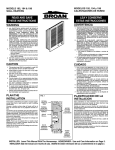
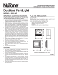
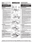
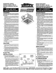
1
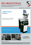
CALENTADOR DE PARED
IMPULSADO POR VENTILADOR
FAN-FORCED WALL
HEATER
READ AND SAVE
THESE INSTRUCTIONS
LEA Y CONSERVE
ESTAS INSTRUCCIONES
WARNING
ADVERTENCIA
1. ALL ELECTRICAL WORK MUST BE DONE IN
ACCORDANCE WITH LOCAL OR NATIONAL
ELECTRICAL CODE AS APPLICABLE. FOR
SAFETY, THIS PRODUCT MUST BE
GROUNDED. IF YOU ARE UNFAMILIAR WITH
METHODS OF INSTALLING ELECTRICAL WIRING, SECURE THE SERVICES OF A QUALIFIED
ELECTRICIAN.
2. WHEN WIRING, SERVICING OR CLEANING
THIS UNIT, TURN OFF POWER AND LOCK OUT
SERVICE PANEL. FAILURE TO DO SO COULD
ALLOW OTHERS OR THERMOSTAT TO TURN
ON POWER UNEXPECTEDLY WHICH MAY
CAUSE FATAL ELECTRICAL SHOCK.
3. To avoid electrical shock:
• DO NOT install unit in a tub or shower enclosure or any location where it may come in contact with water.
• NEVER place a switch where it can be reached
from a tub or shower.
4. DO NOT install this unit in an area where chemicals or other flammables are stored or used. Explosion and fire may result.
1. TODO EL TRABAJO ELECTRICO DEBE REALIZARSE
DE ACUERDO CON LOS CODIGOS ELECTRICOS
LOCALES Y/O NACIONALES CORRESPONDIENTES.
PARA SU SEGURIDAD, ESTE PRODUCTO DEBE
SER CONECTADO A TIERRA. SI USTED NO ESTA
FAMILIARIZADO CON LOS METODOS DE
INSTALACION DEL CABLEADO ELECTRICO,
OBTENGA LOS SERVICIOS DE UN ELECTRICISTA
COMPETENTE.
2. AL HACER EL CABLEADO, LIMPIAR O DAR SERVICIO
A ESTA UNIDAD, DESCONECTE LA POTENCIA Y
TRABE EL PANEL DE SERVICIO. EL NO HACERLO
PUEDE HACER POSIBLE QUE OTRAS PERSONAS
O EL TERMOSTATO RESUMA LA POTENCIA EN
FORMA INESPERADA, LO QUE PUEDE CAUSAR UN
GOLPE ELÉCTRICO MORTAL.
3. Para evitar golpe eléctrico:
• NO instale la unidad en una bañera o recinto de ducha.
• NUNCA coloque un interruptor en un lugar que pueda
ser alcanzado desde una bañera o ducha.
4. NO instale esta unidad en un área donde se almacenen
o usen productos químicos u otros productos inflamables.
De lo contrario, pueden producirse explosiones e
incendios.
CUIDADO
CAUTION
1. Este producto SOLAMENTE se puede instalar en una
pared. NO LO MONTE EN NINGUNA OTRA POSICION.
2. Instale el calentador por lo menos a 15,24 cm (6 pulg.)
de distancia del piso o de alguna superficie vertical
adyacente.
3. NO COLOQUE el calentador detrás de una puerta,
muebles, cortinas, etc., donde el flujo de aire a la unidad
se encuentre restringido.
4. Proporcione al calentador un circuito eléctrico de
capacidad adecuada, a fin de impedir la desconexión
de disyuntores o quemado de fusibles. (Véase el
diagrama abajo).
5. NO CONECTE EL CALENTADOR A UN VARIADOR DE
LUZ O CONTROL DE VELOCIDAD.
6. Para evitar daños al cojinete del motor e impulsores
ruidosos y/o desequilibrados, mantenga la unidad de
potencia lejos de rocíos de yeso, polvo de construcción,
etc.
7. Para más información y requisitos, lea la etiqueta de
especificación sobre el producto.
1. This product may ONLY be installed horizontally
in a wall. DO NOT MOUNT IN ANY OTHER POSITION.
2. Install heater at least 6” from floor or any adjacent vertical surface.
3. DO NOT locate heater behind a door, furniture,
drapes, etc., where the air flow to the unit would
be restricted.
4. Provide heater with an appropriately-rated electrical circuit to prevent tripped breakers or blown
fuses. (See chart below).
5. DO NOT CONNECT HEATER TO DIMMER
SWITCH OR SPEED CONTROL.
6. To avoid motor bearing damage and noisy and/
or unbalanced impellers, keep drywall spray, construction dust, etc., off power unit.
7. Please read specification label on product for further information and requirements.
PLAN THE
INSTALLATION
PLANIFICACION
DE LA INSTALACION
This heater is intended to be used to suppply supplemental heat from a wall location in new or existing
construction.
The heater can be operated using its built-in thermostat or a remote thermostat (Broan Model 86 LineVoltage Thermostat - purchase separately).
Plan to supply the heater with proper line voltage and
appropriate power cable.
NOTE: Power can be tapped from a nearby circuit
depending on the heater wattage required and the
amperage rating of the circuit.
The table below lists the ratings for each model.
MODELS
VOLTS
AMPS
WATTS
BTU/HR
170
120
240
208
8.33/4.16
4.16
3.61
1000/500
1000
750
3413/1707
3413
2560
120
240
208
12.5/6.25
6.25
5.41
1500/750
1500
1125
5120/2560
5120
3840
240
208
8.33/4.16
7.21/3.61
2000/1000
1500/750
6827/3413
5120/2560
174
178
FIG. 1
DRYWALL
PARED DE
YESO
GRILLE
REJILLA
WALL
STUD
VIGA DE
PARED
HEATER
HOUSING
CAJA DEL
CALENTADOR
BUILT-IN
THERMOSTAT
TERMOSTATO
INCORPORADO
POWER
CABLE
CABLE DE
POTENCIA
ELECTRICA
Este calentador ha sido diseñado para proporcionar
calefacción adicional desde la pared en una construcción
nueva o una ya existente.
El calentador se puede poner en funcionamiento usando
su termostato incorporado o un termostato a distancia
(termostato de tensión de línea Broan modelo 86 adquiéralo en forma separada).
Planifique ponerele al calentador la tensión eléctrica y
cable de potencia apropiados.
NOTA: La potencia se puede tomar de un circuito cercano
dependiendo del vatiaje requerido en el calentador y el
amperaje del circuito.
La tabla que aparece a continuación enumera las
corrientes nominales para cada modelo.
MODELOS
VOLTIOS
AMPS
VATIOS
BTU/HR
170
120
240
208
8.33/4.16
4.16
3.61
1000/500
1000
750
3413/1707
3413
2560
174
120
240
208
12.5/6.25
6.25
5.41
1500/750
1500
1125
5120/2560
5120
3840
178
240
208
8.33/4.16
7.21/3.61
2000/1000
1500/750
6827/3413
5120/2560
INSTALLER: Leave This Manual With The Homeowner. HOMEOWNER: Use and Care Information on Page 3.
INSTALADOR: Deje este manual con el dueño de casa. DUEÑO DE CASA: Información del uso y mantenimiento en la página 3.
BOLD ratings are factory wired. See “OPTIONAL WIRING CONVERSIONS” section on page 3 for wattage
and voltage conversion instructions.
Heater can be converted to half-wattage to avoid overloading such circuits.
Follow these basic steps when installing this heater.
• Nail housing to studs.
• Connect power cable.
• Fasten heater assembly and grille to housing.
(FIG. 1)
PREPARE
THE HOUSING
Las corrientes nominales en letras oscuras indican
cableados en fábrica. En la página 3, sección
“CONVERSIONES DE CABLEADO OPCIONAL”
encontrará las instrucciones de conversión de vatiaje y
voltaje.
El calentador se puede convertir a medio vatiaje para
evitar la sobrecarga de dichos circuitos.
Al instalar este calentador, siga estos pasos básicos:
• Clave la caja a las vigas de pared.
• Conecte el cable de potencia
• Fije el equipo del calentador y rejilla a la caja. (FIG. 1)
FIG. 2
PREPARACION DE LA
CAJA
FIG. 3
1. Quite el tornillo de retención, desenchufe el cableado
preconfigurado y levante el equipo del calentador de la
caja. (FIG. 2)
2. Saque la cubierta del cableado de la caja. (FIG. 3)
1. Remove the retaining screw, unplug wiring harness and lift heater assembly from housing. (FIG.
2)
2. Slide the wiring cover out of housing. (FIG. 3)
INSTALACION DEL
CALENTADOR
INSTALL THE HEATER
(16”-ON-CENTER STUDS ONLY)
1. Choose which side of housing will be mounted
directly to a wall stud. Then, insert a mounting
bracket, from the opposite side, into the channel
at the top of housing. (FIG. 4)
NOTE: Locate housing at least 6” from the floor
and any adjacent walls.
2. Use measuring guide on side of housing to position housing so that it will be flush with finished
wall. Drive two (2) nails through the holes in side
of housing and into stud. (FIG. 5)
3. Extend mounting bracket, level housing, and nail
to other stud. (FIG. 6)
(24”-ON-CENTER STUDS ONLY)
1. Choose which side of housing will be mounted
directly to a wall stud. From this side, push a
mounting bracket as far as possible into the channel at the top of housing. (FIG. 4)
NOTE: Locate housing at least 6” from the floor
and any adjacent walls.
2. Use measuring guide on side of housing to position housing so that it will be flush with finished
wall. Drive two (2) nails through the holes in side
of housing and into stud. (FIG. 5)
3. Secure the two (2) mounting brackets together
(with screw supplied). Level housing and nail to
opposite stud, as shown. (FIG. 7)
WIRE THE HEATER
(ALL INSTALLATIONS)
1. Feed electrical power cable through open knockout in corner of housing and attach with appropriate connector. Allow 6” of wire inside of housing.
(FIG. 8)
NOTE: Use other housing knockout when wiring
units in parallel.
2. Connect black to black, white to white. Use
grounding clip to attach green or bare wire to
housing. Replace wiring cover. (FIG. 8)
FIG. 4
FIG. 5
MEASURING
GUIDE/GUIA
DE MEDIDA
FIG. 6
CABLEADO
DEL CALENTADOR
(TODAS LAS INSTALACIONES)
1. Pase el cable de potencia por la abertura del disco
removible que se sáco de la esquina de la caja, y conecte
con el conector adecuado. Deje 15,24 cm (6") de cable
dentro de la caja. (FIG. 8)
NOTA: Al hacer el cableado de unidades en paralelo,
use otros discos removibles de la caja.
2. Conecte negro a negro, blanco a blanco. Use el clip de
tierra para conectar el cable verde o descubierto a la
caja. Coloque de nuevo la cubierta del cableado. (FIG.
8)
FIG. 7
OPTIONAL WIRING
CONVERSIONS
1. Conversion to half-wattage. (FIGS. 9 & 10)
The heater will produce less heat and use less
electricity if converted to half-wattage.
Disconnect ONE of the two (2) black wires (with
insulated terminals) from the motor.
2. 120 VAC to 240 VAC Conversion (FIGS. 11 & 12)
(Factory-wired 120 VAC Models 170 and 174 ONLY)
These heaters can be converted to operate on
240 VAC.
1) Disconnect ONE of the two (2) black wires
(with insulated terminals) from the motor.
2) Disconnect the two (2) white wires (with insulated terminals) from each other. Do not remove the white wire from beneath plastic wire
tie.
3) Connect the black wire to the white wire.
NOTE: When heater is converted from 120 VAC to
240 VAC, half-wattage conversion is not possible.
(40,64 cm (16") EN EL CENTRO DE DOS VIGAS)
1. Escoja qué lado de la caja se montará directamente a
una viga de pared. Desde el lado opuesto, meta un
soporte de montaje en el canal en la parte de arriba de
la caja. (FIG. 4)
NOTA: Coloque la caja a una distancia de por lo menos
15,24 cm (6 pulg.) del piso o de cualquier pared
adyacente.
2. Use la guía de medida en el costado de la caja para
colocar ésta a nivel con la pared terminada. Clave dos
(2) clavos pasándolos por los agujeros al costado de la
caja y en la viga. (FIG. 5)
3. Extienda el soporte de montaje, nivele la caja y clave a
la otra viga. (FIG. 6)
(60,96 cm (24 PULG.) EN EL CENTRO DE DOS VIGAS)
1. Escoja qué lado de la caja se montará directamente a
una viga de pared. Desde el lado opuesto, meta un
soporte de montaje en el canal en la parte de arriba de
la caja. (FIG. 4)
NOTA: Coloque la caja a una distancia de por lo menos
15,24 cm (6 pulg.) del piso o de cualquier pared
adyacente.
2. Use la guía de medida en el costado de la caja para
colocar la caja a nivel con la pared terminada. Clave
dos (2) clavos pasándolos por los agujeros al costado
de la caja y en la viga. (FIG. 5)
3. Fije los dos (2) soportes de montaje (con el tornillo que
se provee). Nivele la caja y clave a la viga opuesta, tal
como se muestra. (FIG. 7)
NAIL
HERE/
MEASURING
GUIDES/
GUIAS DE
MEDIDA
FIG. 8
CLAVE
AQUI
GROUNDING CLIP/
SUJETADOR PARA
CONEXION A TIERRA
CONVERSIONES DE
CABLEADO OPCIONAL
1. Conversión a mitad de vatiaje. (FIGS. 9 & 10)
El calentador producirá menos calor y usará menos
electricidad si se le convierte a mitad de vatiaje.
Desconecte UNO de los dos (2) alambres negros (con
los terminales aisladas) del motor.
2. Conversión de 120 VCA a 240 VCA. (FIGS. 11 & 12)
(SOLAMENTE Modelos 170 & 174 de 120 VCA cableados
en fábrica).
Estos calentadores se pueden convertir de modo que
puedan funcionar con 240 VCA.
1) Desconecte UNO de los dos (2) alambres negros
(con los terminales aisladas) del motor.
2) Desconecte los dos (2) alambres blancos (con
terminales aisladas). No quite el alambre blanco de
abajo del enlace del cable plástico.
3) Conecte el alambre negro al alambre blanco.
NOTA: Cuando el calentador se convierte de 120 VAC a
240 VAC, no es posible la conversión a mitad de vatiaje.
USE AND CARE
WARNING
DISCONNECT FOR
HALF-WATTAGE
DESCONECTE PARA
BLK
MEDIO VATIAJE
NEGRO
BLK
BLK
HEATING NEGRO NEGRO THERMAL
OVERLOAD
ELEMENT
SOBRECARGA
ELEMENTO
M
TERMICA
BLK
NEGRO
(NEW CONSTRUCTION)
1. A housing mask has been provided to keep construction dust, drywall spray, paint, etc. from damaging heater.
Bend the flaps on the mask and push it into the
heater housing.
NOTE: Mask can be put in place before or after
heater assembly is re-installed.
2. Remove mask before operation.
(ALL INSTALLATIONS)
3. Secure heater assembly with retaining screw and
plug wiring harness into receptacle.
4. Fasten grille to heater with two (2) screws provided. (FIG. 13)
5. Push knob onto thermostat stem.
6. Turn on power at service entrance. Turn thermostat to its highest setting and make sure heating
element and blower come on. Then make sure
element and blower shut off at lowest thermostat
setting.
FIG. 9
DE CALOR
WHT
BLANCO
FACTORY-WIRED
HEATER (FULL
WATTAGE)
CALENTADOR
CABLEADO EN
FABRICA (VATIAJE
COMPLETO)
WHT
WHT
BLANCO BLANCO
BLK
BLK
NEGRO NEGRO
COMPLETE
THE INSTALLATION
THERMOSTAT
TERMOSTATO
LINE IN LINEA DE ENTRADA
FIG. 10 - HALF-WATTAGE CONVERSION
CONVERSIÓN DE MEDIO VATIAJE
(2) BLACK WIRES (connected to motor)
(2) CABLES NEGROS (conectados al motor)
(NUEVA CONSTRUCCIÓN)
1. Se provee una cubierta de caja para evitar que el polvo
de la construcción, rocíos de yeso, pintura, etc., dañen
el calentador.
Doble las aletas de la cubierta y póngala dentro de la
caja del calentador.
NOTA: La cubierta se debe colocar en su lugar antes o
después de reinstalar el equipo del calentador.
2. Quite la cubierta antes del funcionamiento.
(TODAS LAS INSTALACIONES)
3. Fije el conjunto del calentador con el tornillo de retención
y conecte el conjunto preconfigurado de cables al
enchufe.
4. Sujete la rejilla al calentador con los dos (2) tornillos que
se proveen. (FIG. 13)
5. Empuje la perilla en el vástago del termostato.
6. Conecte la potencia en la entrada de servicio. Active el
termostato en su graduación más alta y compruebe que
se activan el elemento de calor y el soplador. Luego
compruebe que el elemento y el soplador se apaguen
en la graduación de termostato más baja.
USO Y MANTENIMIENTO
ADVERTENCIA
DISCONNECT ELECTRIC POWER AT SERVICE
ENTRANCE BEFORE CLEANING OR SERVICING UNIT.
THERMAL OVERLOAD PROTECTOR
If heater fails to operate when thermostat is turned to
its highest setting: Turn power off at service entrance.
Remove knob and grille and press button marked “RESET”.
CLEANING
Clean the heater assembly using the round brush tool
on your vacuum cleaner. Remove large accumulations
of dust, lint, etc., that might impede the flow of air
through the heater. Such blockage will lower its efficiency and create a possible over-heating condition.
To clean grille, use a soft cloth which has been moistened with household window cleaner.
CAUTION: METAL AND ELECTRICAL PARTS
SHOULD NEVER BE IMMERSED IN WATER.
COMPLETE
LA INSTALACION
DESCONECTE LA ENERGIA ELECTRICA EN LA
ENTRADA DE SERVICIO ANTES DE HACER LA
LIMPIEZA O DAR SERVICIO A LA UNIDAD.
MOTOR
FIG. 11 - 120VAC TO 240VAC CONVERSION
CONVERSIÓN DE 120VCA A 240VCA
WHITE WIRES
CABLES BLANCOS
BLACK WIRE (from motor)
CABLE NEGRO (del motor)
PROTECTOR DE SOBRECARGA TERMICA
Si el calentador no funciona cuando el termostato está
prendido en su graduación más alta, desconecte la
potencia en la entrada de servicio. Quite la perilla y la rejilla
y oprima el botón marcado “RESET”.
LIMPIEZA
Limpie el calentador con el cepillo redondo de su
aspiradora. Quite las acumulaciones de polvo, pelusa, etc.,
que puedan impedir el flujo de aire a través del calentador.
Ese bloqueo disminuirá la eficiencia y creará una posible
condición de sobrecalentamiento.
Para limpiar la rejilla, use un paño humedecido con
limpiador de ventanas casero.
CUIDADO: LAS PIEZAS METALICAS Y ELECTRICAS
NUNCA SE DEBEN SUMERGIR EN AGUA.
MOTOR
BLK
NEGRO
WHT
BLANCO
CONVERTED 240
VAC HEATER
CALENTADOR 240
VCA CONVERTIDO
WHT
WHT
BLANCO BLANCO
WHT
BLANCO
M
THERMAL
OVERLOAD
SOBRECARGA
TERMICA
BLK
NEGRO
HEATING
ELEMENT
ELEMENTO
DE CALOR
BLK
NEGRO
BLK
BLK
NEGRO NEGRO
BLK
NEGRO
BROAN ONE YEAR LIMITED WARRANTY
Broan warrants to the original consumer purchaser of its products that such products will be free from defects in materials or
workmanship for a period of one year from the date of original
purchase. THERE ARE NO OTHER WARRANTIES, EXPRESS
OR IMPLIED, INCLUDING, BUT NOT LIMITED TO, IMPLIED WARRANTIES OF MERCHANTABILITY FITNESS FOR A PARTICULAR PURPOSE.
During this one-year period, Broan will, at its option, repair or
replace, without charge, andy product or part which is found to
be defective under normal use and service.
THIS WARRANTY DOES NOT EXTEND TO FLUORESCENT
LAMP STARTERS AND TUBES. This warranty doen not cover (a)
normal maintenance and service or (b) any products or parts
which have been subject to misuse, negligence, accident, improper maintenance or repair (other than by Broan), faulty installation or installation contrary to recommended installation instructions.
The duration of any implied warranty is limited to the one-year
peiod as specified for the express warranty. Some states do not
allow limitation on how long an implied warranty lasts, so the
above limitation may not apply to you.
BROAN’S OBLIGATION TO REPAIR OR REPLACE, AT BROAN’S
OPTION, SHALL BE THE PURCHASER’S SOLE AND EXCLUSIVE REMEDY UNDER THIS WARRANTY. BROAN SHALL NOT
BE LIABLE FOR INCIDENTAL, CONSEQUENTIAL OR SPECIAL
DAMAGES ARISING OUT OF OR IN CONNECTION WITH PRODUCT USE OR PERFORMANCE. Some states do not allow the
exclusion or limitation of incidental or consequential damages,
so the above limitation or exclusion may not apply to you.
This warranty gives you specific legal rights, and you may also
have other rights, which vary from state to state. This warranty
supersedes all prior warranties.
To qualify for warranty service, you must (a) notify Broan at the
address or telephone number below, (b) give the model number
and part identification and (c) describe the nature of any defect
in the product or part. At the time of requesting warranty service,
you must present evidence of the original purchase date.
Broan-NuTone LLC, 926 West State Street, Hartford, WI 53027
WHT
BLANCO
FIG. 12
THERMOSTAT
TERMOSTATO
240 VAC LINE IN
LINEA DE ENTRADA 240 VCA
FIG. 13
GARANTIA BROAN LIMITADA POR UN AÑO
Broan garantiza al consumidor comprador original de sus productos
que dichos productos carecerán de defectos en materiales o en mano
de obra por un período de un año a partir de la fecha original de compra.
NO EXISTEN OTRAS GARANTIAS, NI EXPLICITAS NI IMPLICITAS,
INCLUYENDO, PERO NO LIMITADAS A, GARANTIAS IMPLICITAS DE
COMERCIALIZACION O APTITUD PARA UN PROPOSITO PARTICULAR.
Durante el período de un año, y a su propio criterio, Broan reparará o
reemplazará, sin costo alguno, cualquier producto o pieza que se
encuentre defectuosa bajo condiciones normales de servicio y uso.
ESTA GARANTIA NO SE APLICA A TUBOS Y ARRANCADORES DE
LAMPARAS FLUORESCENTES. Esta garantía no cubre (a)
mantenimiento y servicio normales ni (b) cualquier producto o piezas
que hayan sido utilizadas de forma errónea, negligente, que hayan
tenido un accidente, o que hayan sido reparadas o mantenidas
incorrectamente (por otras compañías que no sean Broan), instalación
defectuosa, o instalación contraria a las instrucciones de instalación
recomendadas.
La duración de cualquier garantía implícita se limita a un período de
un año como se especifica en la garantía expresa. Algunos estados
no permiten limitaciones en cuanto al tiempo de expiración de una
garantía implícita, por lo que la limitación antes mencionada puede
no corresponderle.
LA OBLIGACION DE BROAN DE REPARAR O REEMPLAZAR,
SIGUIENDO EL CRITERIO DE BROAN, DEBERA SER EL UNICO Y
EXCLUSIVO RECURSO LEGAL DEL COMPRADOR BAJO ESTA
GARANTIA. BROAN NO SERA RESPONSABLE POR DAÑOS
INCIDENTALES, CONSIGUIENTES, O POR DAÑOS ESPECIALES
RESULTANTES A RAIZ DEL USO O DESEMPEÑO DEL PRODUCTO.
Algunos estados no permiten la exclusión o limitación de daños
incidentales o consiguientes, por lo que la limitación antes
mencionada puede no aplicarse a usted.
Esta garantía le proporciona derechos legales específicos, y usted
puede también tener otros derechos, los cuales varían de estado a
estado. Esta garantía reemplaza todas las garantías anteriores.
Para tener derecho al servicio de garantía, usted debe (a) notificar a
Broan en la dirección o al número de teléfono que se menciona abajo,
(b) dar el número del modelo y la identificación de la pieza, y (c)
describir la naturaleza de cualquier defecto en el producto o pieza. En
el momento de solicitar servicio cubierto por la garantía, usted debe
presentar comprobación de la fecha original de compra.
Broan-NuTone LLC, 926 West State Street, Hartford, WI 53027
SERVICE PARTS
PIEZAS DE SERVICIO
FAN-FORCED WALL
HEATERS
CALENTADOR DE PARED
IMPUSADO POR VENTILADORS
KEY NO.
NUMERO
DE CODIGO
PART NUMBER
NUMERO DE
PIEZAS
1
2
3
4
5
6
7
8
97008681
98003036
99260512
99390015
97005422
98006975
99020130
99080248
99080252
99270735
99030194
99271091
98006974
99150491
99270741
99270725
99270742
93270619
97008682
99260428
97008675
97008677
97008678
99030191
98006973
99260464
99150533
98006970
99150528
99360135
99090681
93270493
99150470
9
10
11
12
13
14
15
16
17
18
19
20
21
22
23
24
25
26
27
28
29
30
DESCRIPTION
DESCRIPCION
Housing
Mounting Bracket (2 Required)
#8-18 Sheet Metal Nut (2 Required)
Ground Clip
Receptacle Assembly
Wiring Cover
Blower Wheel
Motor (Models 170 & 174)
Motor (Model 178)
Tab Adaptor
Thermal Overload
Guard
Element Bracket
Screw, #8-18 x 3/8 Ph. Pan Head (7 Required)
Heating Element (Model 170)
Heating Element (Model 174)
Heating Element (Model 178)
Wire Clamp
Partition Plate Assembly
Nut, #6-32 x 5/16 Keps (2 Required)
Plug Assembly
Thermostat Wire Assembly
Overload Wire Assembly
Thermostat
Thermostat Bracket
Lock Nut
Screw, #8-18 x 5/8 Ph. Pan Head
Grille
Grille Screw (2 Required)
Knob
Grille Logo
Wire Tie
Screw, #8-18 x 3/8 Ph. Truss Hd.
Caja
Soporte de montaje (se requieren 2)
Tuerca de chapa metálica #8-18 (se requieren 2)
Clip de tierra
Conjunto del enchufe
Cubierta del cableado
Rueda del soplador
Motor (Modelos 170 & 174)
Motor (Modelo 178)
Adaptador de lengua
Sobrecarga térmica
Dispositivo de protección
Soporte del elemento
Tornillo, cabeza de chanfle #8-18 x 3/8 (se requieren 7)
Elemento de calor (Modelo 170)
Elemento de calor (Modelo 174)
Elemento de calor (Modelo 178)
Sujetador del alambre
Equipo de placa de partición
Tuerca, keps #6-32 x 5/16 (se requieren 2)
Conjunto del enchufe
Conjunto de cableado del termostato
Conjunto de cableado de la sobrecarga
Termostato
Soporte de termostato
Contratuerca
Tornillo, cabeza chanfle . #8-18 x 5/8
Rejilla
Tornillo de rejilla (se requieren 2)
Perilla
Logotipo de la rejilla
Enlace de cable
Tornillo, cabeza “truss” 8-18 x 3/8 (se requieren 2)
Always order replacement parts by" PART NUMBER" - NOT "KEY NUMBER". Encargue piezas de repuesto por "NUMERO DE PIEZAS" -NO por "NUMERO DE
CODIGO".
99041219L