1
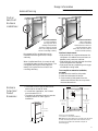
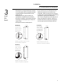
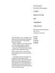
GE Monogram® Installation Instructions Stainless Steel Bottom Mount Built-In Refrigerators Models ZICS36N RH ZICS36N LH Before you begin - Read these instructions completely and carefully. IMPORTANT - Save these instructions for local inspector’s use. IMPORTANT - OBSERVE ALL GOVERNING CODES AND ORDINANCES. Note to Installer - Be sure to leave these instructions with the Consumer. Note to Consumer - Keep these instructions with your Use and Care Book for future reference. CAUTION WARNING This appliance must be properly grounded. See “Grounding the Refrigerator,” page 6. If you have a question concerning the installation of this product, call the GE Answer Center® Consumer Information Service at 800.626.2000, 24 hours a day, 7 days a week. If you received a damaged refrigerator, you should immediately contact your dealer or builder. Proper installation is the responsibility of the installer. Product failure due to improper installation is not covered under the GE Appliance Warranty. See the Use & Care Guide for warranty information. Contents WARNINGS: • Use this appliance only for its intended purpose. • Immediately repair or replace electric service cords that have become frayed or damaged. • Unplug the refrigerator before cleaning or making repairs. • Repairs should be made by a qualified service technician. For Monogram local service in your area, 1-800-444-1845. For Monogram Service in Canada 1-888-880-3030. For Monogram Parts and Accessories, call 1-800-626-2002. Design Information Flush or Semi-Flush Enclosure Installations ................................................................................... 3 Enclosure Cutout and Product Dimensions ................................................................................... 3 Installation Examples ........................................................................................................................ 4 Installation Preparation Water Connection Location, Electrical ............................................................................................ 5 Product Dimensions & Clearances .................................................................................................. 5 Grounding the Refrigerator ............................................................................................................. 6 Tools Required .................................................................................................................................. 7 Materials Required ............................................................................................................................ 7 Hardware Supplied ........................................................................................................................... 7 Optional Hardware ........................................................................................................................... 7 Flooring .............................................................................................................................................. 7 Step 1: Remove Packaging ................................................................................................................ 7 Installation Instructions Step 2: Install Water Line ................................................................................................................. 8 Step 3: Install Side Panels ................................................................................................................ 9 Step 4: Install Anti-Tip Brackets ..................................................................................................... 10 Step 5: Level Refrigerator ............................................................................................................... 10 Step 6: Optional Anti-Tip Precaution ............................................................................................ 10 Step 7: Connect Water Supply ........................................................................................................ 11 Step 8: Connect Power .................................................................................................................... 11 Step 9: Mount Top Grill Panel ....................................................................................................... 11 Step 10: Install Toekick ................................................................................................................... 12 Step 11: Set Temperature Controls................................................................................................ 12 Step 12: Start Icemaker ................................................................................................................... 12 ZFC1 Trim Kit for Side to Side Installation .................................................................................... 13 Problem Solving .............................................................................................................................. 14 2 Design Information 36" Stainless Bottom Mount Refrigerators Advance Planning Flush or Semi-Flush Enclosure Installations 0" 3/4" True Flush Installation In a flush installation, the refrigerator doors will align evenly with the front face of adjacent cabinet doors. The refrigerator blends into the surrounding cabinetry. Monogram built-in refrigerators can be installed flush with typical 24-3/4" deep cabinetry. When installed semi-flush, the case trim will conceal slight gaps around the enclosure. The refrigerator will project forward approximately 3/4" beyond the front face of surrounding cabinetry. Enclosure Cutout and Product Dimensions • To achieve a flush fit the finished cutout width must be at least 36" wide. • In a semi-flush installation, the finished cutout must be 35-1/2". • The electrical and water locations must be located as shown for either type of installation. Semi-Flush Installation These refrigerators can also be installed semi-flush into an enclosure using the minimum cutout width. The case trim creates a frame around the opening. Side Panels Requirements: • Side panels are not required whenever the refrigerator is installed into an enclosure or between pantry and oven cabinets. • Side panels are required whenever the sides of the refrigerator are exposed. • Side panel sizes vary depending on the type of installation being made. To accomplish an attractive installation, you must: 1. Determine the need for side panels. 2. Determine side panel thickness. 3. Order matching side panels from the cabinet manufacturer. Be sure to provide the exact dimensions. *Finished Width 24-3/4" 36" Wall View 7" 5" 84 1/2" max 83 1/2" min Finished Opening 24 3/4" Total Depth 5" 83-1/2" Min 84-1/2" Max Electrical Area 7 1/2" Water Supply 74" From Floor to Bottom of Electrical 5" 3 1/2" 3 1/2" *36" for for a flush installation. 35-1/2" Min. for a semi-flush installation. Note: Additional cutout width may be required when side panels are used. Add side panel thickness to the finished cutout to calculate rough-in width. See installation examples on the following page. 3 Design Information 36" Stainless Bottom Mount Refrigerators Side panels are required whenever the sides of the refrigerator will be exposed. 1/2" to 3/4" side panels are normally set into place and fastened to adjacent cabinetry or to the back wall before rolling the refrigerator into the opening. Therefore, the rough-in dimensions must allow for side panel thickness. In both a flush and semi-flush installation, the finished dimension, (the width of the opening after side panels are installed), must accommodate the full width of the refrigerator. See page 9 for side panel sizes. Installation Between Base & Wall Cabinets Flush and Semi-Flush Installations 1/4" Thick Side Panels Finished Dim. Roughed-In Dim. Refrigerator Cabinet 35-1/2" 36" Refrigerator door NOTE: 1/4" thick side panels can be inserted into the case trim, making the rough-in the same as the outside trim width, 36". Installation At End-of-Run Cabinet 1/4" Side Panels. Insert end of side panel into trim Flush and Semi-Flush Installations 1/2" Thick Side Panels Finished Dim. 36" Roughed-In Dim. 37" Refrigerator Cabinet Refrigerator door Cabinet 1/2" To 3/4" Side Panels. Leading Edge Flush With Cabinet NOTE: 1/2" thick side panels shown. Side panels can be any thickness. Add side panel thickness to outside trim width (36") to calculate the rough-in dimension. The leading (front) edge must be finished to match surrounding cabinetry. Frameless Cabinets Side panels, 1/2" minimum thickness are required when using frameless cabinets. The side panel acts as a spacer between the cabinet and the case trim and prevents interference with cabinet door swing. The leading (front) edge must be finished to match surrounding cabinetry. 1/2" To 3/4" Side Panels. Leading Edge Flush With Cabinet Refrigerator Cabinet Refrigerator door 4 Installation Preparation 36" Stainless Bottom Mount Refrigerators Product Dimensions ZICS36N RH Handle on the left side, the door swings left to right. ZICS36N LH Handle on the right side, the door swings right to left. A – 36" outside trim width B – 35" case width C – 10-3/4" D – 72-1/4" E – 84" Shipping height Adjustable from 83-1/2" to 84-1/2" F – 24-3/4" (excluding handles) G – 26-3/4" (including handles) H – 4" G A B F C E D Caution: Refrigerators are much heavier at the top than at the bottom – be extra careful when moving. H Clearances Electrical and Water Connection Locations These refrigerators are equipped with special hinges that allows the door to swing out and away from the cabinet. No clearances are required on the sides. Electrical Outlet The water line can be routed through Location 7-1/2" the floor or back wall. • Water line should be: –Approximately 3-1/2" from the floor on the back wall, or 3-1/2" from the back wall on the floor. –At least 5" from either side of the opening. A 115 volt, 60 Hz. 15 or 20 amp power supply is required. An individual properly grounded branch circuit or circuit breaker is recommended, as noted on the rating plate. The rating plate is located on the top on the evaporator box and is visible when grille panel is removed. • Locate the electrical outlet within 5" x 7" shaded area shown. –7-1/2" from the left side. • Between 74" and 81" from the floor. Accessory Grille Panel Kits When the refrigerator is installed in a corner: • A 4" min. clearance on the hinge side will assure a 90° door opening and access to all drawers. • A 10" clearance on the hinge side is required for removal of pans. These models are factory set for 84" installation height. Adjustments to 83-1/2" or 84-1/2" heights can be made by changing the grille panel. 7" 5" 74" 5" 3-1/2" Water Location Important: To insure a flush fit and access to the power cord, locate the electrical outlet as shown. Order ZGCSS36RH (right hand) or ZGCSS36LH (left hand) Grille Panel Kit. These kits include 2 grille panels, for 83-1/2" and 84-1/2" installation heights. 5 Installation Preparation 36" Stainless Bottom Mount Refrigerators Grounding the Refrigerator IMPORTANT - (Please read carefully) FOR PERSONAL SAFETY, THIS APPLIANCE MUST BE PROPERLY GROUNDED. The power cord of this appliance is equipped with a three-prong (grounding) plug which mates with a standard three-prong (grounding) wall receptacle to minimize the possibility of electric shock hazard from this appliance. Have the wall outlet and circuit checked by a qualified electrician to make sure the outlet is properly grounded. DO NOT, UNDER ANY CIRCUMSTANCES, CUT OR REMOVE THE THIRD (GROUND) PRONG FROM THE POWER CORD. Where a standard 2-prong wall outlet is encountered, it is your personal responsibility and obligation to have it replaced with a properly grounded 3-prong wall outlet. Use of Adapter plug Because of potential hazards under certain conditions, we strongly recommend against use of an adapter plug. However, if you still elect to use an adapter, where local codes permit, a TEMPORARY CONNECTION, may be made to a properly grounded 2-prong wall outlet by use of a UL listed adapter available at most hardware stores. The larger slot in the adapter must be aligned with the larger slot in the wall outlet to provide proper polarity in the connection of the power cord. CAUTION: Attaching the adapter ground terminal to a wall outlet cover screw does not ground the appliance unless the cover screw is metal, and not insulated, and the wall outlet is grounded through the house wiring. You should have the circuit checked by a qualified electrician to make sure the outlet is properly grounded. When disconnecting the power cord from the adapter, always hold the adapter in place with one hand and pulling the power cord with the other hand. If this is not done, the adapter ground terminal is very likely to break with repeated use. Should the adapter ground terminal break, DO NOT USE the appliance until a proper ground has again been established. Use of Extension Cords Because of potential safety hazards under certain conditions, we strongly recommend against the use of an extension cord. However, if you still elect to use an extension cord, it is absolutely necessary that it be a UL listed 3-wire grounding type appliance extension cord having a grounding type plug and outlet and that the electrical rating of the cord be 15 amperes (minimum) and 120 volts. 6 Installation Preparation 36" Stainless Bottom Mount Refrigerators • Appliance Hand Truck • Tubing cutter • 7/16" open-end wrench • #2 Phillips screwdriver • Stubby Phillips screwdriver Tools Required • Tinsnips to cut banding • Stepladder • Bucket • Level Materials Required • Side panels to match cabinetry • 2x4, 36" long, for Anti-Tip support, see page 10 Hardware Supplied • 1-1/2" stamped open-end wrench • Special velcro adhesive strips for 1/4" side panels • 1/4-1/4 union with nuts Hardware Recommendations • Water shut-off valve • Water filter WR97X0214 Flooring For proper installation, this refrigerator must be placed on a level surface of hard material that is at the same height as the rest of the flooring. This surface should be strong enough to support a fully loaded refrigerator. 1 CAUTION: Refrigerator is much heavier at the top than at the bottom – be careful when moving. When using a hand truck, handle from side only. • Remove outer carton. –Carefully cut banding at the top and bottom. • Slide out back corner posts (2). • Slide carton off top of cabinet. • Remove styrofoam pads taped to base cabinet. NOTE: IT IS NOT NECESSARY TO LAY CABINET DOWN IN ORDER TO REMOVE SKID! • To remove skid, remove the four 7/16" bolts and their brackets. CAUTION: DO NOT ATTEMPT TO ROLL UNIT OFF SKID. • There are support blocks on the bottom of the cabinet and door. They must be removed before sliding unit off skid or damage will occur. • Carefully, tilt cabinet and slide blocks out from beneath cabinet, slide unit off skid. • Remove toekick from the fresh food compartment, set aside for later installation. Step Remove Packaging • Drill and appropriate bits • 7/16" socket with 3" extension for ratchet • Safety glasses • Anti-tip mounting brackets CAUTION: Protect the finish of the flooring. Cut a large section of the cardboard carton and place under the refrigerator where you are working. 7/16" Bolt 7 Installation 36" Stainless Bottom Mount Refrigerators 2 Step Install Water Line • A cold water supply is required for automatic icemaker operation. The water pressure must be between 20 and 120 p.s.i. • Route 1/4" OD copper tubing between house cold water line and the water connection location. Floor Copper Tubing • Copper tubing should be long enough to extend to the front of the refrigerator. Allow enough to accommodate bend leading into the water valve. Shut off the main water supply. Turn on the nearest faucet long enough to clear the line of water. Install a shut-off valve between the icemaker water valve and cold water pipe in a basement or cabinet. The shut-off valve should be located where it will be easily accessible. NOTE: It is best to install the valve into a vertical water pipe. If you install the valve into a horizontal water pipe, make the connection at the top or side, rather than at the bottom, to avoid drawing off any sediment from the water pipe. • Drill a 1/4" hole in the water pipe. • Fasten the shut-off valve to the pipe with pipe clamp. • Tighten the clamp screws until the sealing washer begins to swell. Do not over tighten. • Place a compression nut and ferrule (sleeve) onto the end of the tubing and connect it to the shut-off valve. Make sure the tubing is fully inserted into the valve and ferrule is tightened. Washer Pipe Clamp Saddle Type Shutoff Valve Inlet End Vertical Cold Water Pipe Compression Nut Saddle Type Shutoff Valve Packing Nut Outlet Valve Ferrule (Sleeve) • Turn on the main water supply and flush debris from the line. Run about a quart of water through the tubing into a bucket. Shut off water supply at the shut-off valve. NOTE: Saddle type shut-off valves are included in many water supply kits. Before purchasing, make sure a saddle type valve complies with your local plumbing codes. • Install optional water filter in the water line near the refrigerator. A water filter is recommended in areas where water supply contains sand or particles. Installation instructions are packed with the filter. 8 Installation 36" Stainless Bottom Mount Refrigerators 3 Step Install Side Panels • Side panels are required whenever the sides of the refrigerator will be exposed and when installed between frameless cabinets. See pages 3 and 4. • Side panels are not required when the refrigerator is installed into an enclosure. • Side panel installation will be determined by the design of the side panel you have previously chosen. • Side panels must be installed plumb. • If you choose to use 1/4" side panels, they should be inserted into the case trim as illustrated. Fasten the panels to the refrigerator with velcro strips (provided) before setting refrigerator in place. See illustration A. • 1/2" to 3/4" side panels are normally set into place and fastened to adjacent cabinetry or the back wall before rolling the refrigerator into the opening. See illustrations B and C. Illustration A 1/4" Side Panels – Insert end of side panel into case trim. Fasten with Velcro strips included. Illustration B 1/2" to 3/4" Side Panels – Leading edge of side panel is flush with cabinet front. Fasten to the back wall using a cleat. 23-9/16" 84" 24-3/4" 84" Trim 2-9/16" Standard 4" high toekick or trim to fit. Height may vary depending on application. Illustration C 1/2" to 3/4" Side Panels – Recessed front edge of side panel. Fasten to adjacent cabinet. 3-3/4" Standard 4" high toekick or trim to fit. Height may vary depending on application. 23-5/16" 84" 2-5/16" Standard 4" high toekick or trim to fit. Height may vary depending on application. 9 Installation 36" Stainless Bottom Mount Refrigerators 4 Step Install Anti-Tip Brackets Note: If you are installing under a soffit, attach brackets to wood block before mounting the brackets to the rear wall. WARNING CAUTION ANTI-TIP PRECAUTIONS The refrigerator is heavy at the top and must be secured to prevent the possibility of tipping forward. • Mount brackets provided using #12 or #14 wood screws located 83-1/2" from the finished floor. • Screws must protrude at least one inch into vertical wall studs. • Attach a 36" long 2x4 block to brackets as shown. Roll Refrigerator Into Opening • Gently push refrigerator into opening with hands against front corners. The cardboard protective pad should be beneath the refrigerator. • Roll refrigerator into the opening until it is flush or semi-flush with adjacent cabinets. 5 Step Level Refrigerator 6 Step Optional Anti-Tip Precaution Note: Whenever possible, perform this step for additional anti-tip security. This step can be used as an alternate to Step 4, Anti-Tip bracket installation, whenever brackets cannot be used. 83-1/2" From floor to bottom of wood block Mounting Bracket 2 x 4 Cut To 36" Length 83-1/4" From Floor Important Note: If your installation situation does not allow enough height for this method of security, use step 6 as an alternate. The refrigerator must be secured to prevent tipping. This refrigerator has 4-point leveling. The front is supported by leveling legs, the rear is supported by wheels. • Adjust rear wheels beneath the refrigerator to just barely touch the 2x4 block. • Turn the 7/16" hex nut located above the front wheels. Turn to raise or lower the refrigerator. • For front leveling legs, use the 1-1/2" openend wrench (provided). • Adjust carefully, the refrigerator should be level and plumb with cabinetry, and should align with toekick height. 2x4 Block 36" Wide Wood Screws Mounted into Vertical Wood Studs Hex Nut Adjusts Rear Wheels Leveling Leg Stud Refrigerator Cabinet Door Spacer Block OR When using 1/2" to 3/4" side panels, the front flange of the case trim is attached to the side panel. • Open fresh food door to access case trim. • Drill hole in trim below fresh food opening. Drive screw through trim and side panel. • Follow the same procedure on opposite side. If refrigerator is installed between cabinets with no side panels or in a custom enclosure, install a spacer block as shown. • Open fresh food door to access case trim. • Drill hole in trim below fresh food opening. Drive screw through trim and into block. • Follow the same procedure on opposite side. 10 Installation 36" Stainless Bottom Mount Refrigerators 7 Step Connect Water Supply Check to be sure that refrigerator power cord is not plugged into the wall outlet. • Locate and bring copper tubing to the front of the cabinet. • The copper tubing should be just long enough to reach the coupling. Excess tubing length could interfer with drawer closing or toekick installation. • Slip a 1/4-1/4 union nut (provided) over both ends of the copper tubing at the right front leg of the refrigerator and couple the lines. • Turn on the water to check for leaks. 8 • Connect the refrigerator power cord plug to properly grounded receptacle, accessible through the top left side of the hood opening. • Check to make sure power to refrigerator is on by opening refrigerator door to see if interior lights are on. 9 • For shipping purposes, the top case trim is secured at 84" installation height. To raise case trim to 84-1/2" installation height or to lower case trim to 83-1/2": • Loosen 2 screws on both sides and raise or lower the top case trim to meet soffit height or to the top of adjacent cabinets. • Tighten all 4 screws. • Mount the grille panel by dropping into slots on the case trim. Step Connect Power Step Mount Top Grille Panel Screws Top Case Trim Raise To Installation Height The grille panel assembly is factory set for an 84" installation height. If installation height is 83-1/2" or 84-1/2", order ZGCSS36RH (right hand) or ZGCSS36LH (left hand) grille panel kit. 1-1/2" min. gap Important: Maintain 1-1/2" min. gap between top of doors and bottom of grille panel. 11 Installation 36" Stainless Bottom Mount Refrigerators 10 • A standard toekick is supplied. Install with 2 screws provided, adjust to desired height and tighten screws. 11 • Set Fresh Food control at “5”. • Set Freezer control at “5”. 12 • Lower the feeler arm to the ON position and the icemaker will begin operation automatically. • Discard the first few batches of ice cubes to be sure that any remaining impurities in the water line will be flushed out. NOTE: During operation, you will hear the hum of the motor, movement of the cube ejector, humming or clicking of the water valve, and ice falling into the bin. These sounds are normal. Step Install Toekick Step Temperature Controls Step Start Icemaker Important: The vented toekick must remain unobstructed for proper air circulation and operation. 5 IS NORMAL 9 IS COLDEST FREEZER 5 IS NORMAL 9 IS COLDEST FRESH FOOD SET HERE IF MOISTURE APPEARS ON EXTERIOR OFF ENERGY SAVER IMPORTANT: Allow 24 hours for temperatures to stabilize before making adjustments. 12 ZFC1 Trim Kit Side to Side Installation For the ultimate in convenience, install two refrigerators side to side. This trim kit includes 6 foam spacer pads to fill the gap between the refrigerator side case trims. For a finished appearance, a trim strip is provided to conceal the side case trim of the two refrigerators. If you are installing into an enclosure, provide a 72" wide opening. If you are installing where the sides of the refrigerators will be exposed, allow additional width for any side panels used. • Apply foam spacer pads evenly to the side of one refrigerator as shown. • Slide second refrigerator into position. • Check to be sure both refrigerators are level. If they are not level, an obvious gap can be seen between the side trims. Adjust leveling legs if needed. Slight gaps will be concealed with the trim strip. • Open both fresh food doors to access side trim. • The U-shape trim will overlap the side case trim of both refrigerators. • Set the top case trim (see page 11) to installation height. • Hold U-shaped trim strip up against case trim as shown. Mark length with pencil at the point where U-shaped trim overhangs case trim at bottom. • Mark length with a pencil. • Trim excess length. • Starting at the top, press U-shaped trim strip over case trims of both refrigerators. • Continue pressing about half way down. Slide open freezer drawers and continue pressing trim until you reach the bottom of the strip. Foam Spacer Pads Case Trim U-Shape Trim 13 Notes 36" Stainless Bottom Mount Refrigerators 14 Installation 36" Stainless Bottom Mount Refrigerators Problem Solving Moisture If moisture forms between the doors or on the cabinet, turn on the energy saver switch. This should only occur when humidity is high. Operation of Refrigerator If the refrigerator does not operate after checking the installation instructions: • Check the electrical connections inside the cooling compartment. • Check to be sure power cord is plugged in the wall outlet. • Check to be sure that fuse or circuit breaker is turned on. Stainless Steel Magic is available at Ace, True Value, Servistar, HWI and other leading stores. It is also available through GE Parts by calling 1-800-626-2002. Order part number WX10X15. If any of these problems persist: Call for Monogram local service in your area, 1-800-444-1845. Cleaning the Stainless Steel Refrigerator Stainless Steel has some unique cleaning characteristics. In order to keep your refrigerator looking like new, we suggest cleaning it with Stainless Steel Magic or a similar product. 15 Note: While performing installations described in this book, safety glasses or goggles should be worn. To obtain specific information concerning any Monogram product or service, call GE Answer Center® consumer information service at 800.626.2000—any time, day or night. For Monogram local service in your area, call 1-800-444-1845. ® Monogram. General Electric Company Louisville, KY 40225 NOTE: Product improvement is a continuing endeavor at General Electric. Therefore, materials, appearance and specifications are subject to change without notice. Pub. No. 49-6984 1998 GE Appliances (N.D. 978) 8/98 5A95497