1
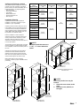
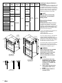
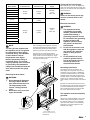
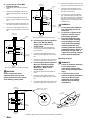
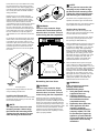
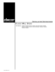
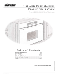
Installation Instructions
Wall Ovens
SAVE AND READ THESE INSTRUCTIONS
TESTED IN ACCORDANCE WITH THE LATEST EDITION OF UL858 STANDARD FOR HOUSEHOLD ELECTRIC
COOKING APPLIANCES.
CONVENTIONS USED IN THESE INSTRUCTIONS
WARNINGS:
Must be followed carefully to avoid personal injury or damage.
NOTES:
Contain helpful hints and tips to facilitate the installation.
IMPORTANT
1.
2.
3.
4.
5.
Before beginning installation, please thoroughly read and become familiar with these instructions.
Installation and service must be completed by a qualified installer or service agency.
Installer: Please leave these Installation Instructions with the owner.
Owner: Please keep these instructions for local electrical inspector’s use and for future reference.
Read the accompanying Use & Care Manual prior to operating this appliance.
TABLE OF CONTENTS
STEP
STEP
STEP
STEP
STEP
STEP
STEP
STEP
STEP
STEP
STEP
1
2
3
4
5
6
7
8
9
10
11
Package contents verification
Installation Planning
Installing the support platform in the cabinet
Electrical power supply requirements
Removing the oven door(s)
Turning of the power supply
Electrical connection
Mounting the oven
Installing the exhaust grill
Re-installing the oven door(s)
Verifying oven operation
Part No. 65030 Rev. C
Page 2
Pages 2-3
Page 3
Pages 3-4
Page 4
Page 4
Pages 4-5
Pages 5-6
Page 6
Page 6
Page 6
IMPORTANT SAFETY INSTRUCTIONS
WARNINGS:
To reduce the risk of burns,
electric shock, fire or injury to
persons:
1.
Read all instructions before
using the appliance.
2.
This appliance must be
grounded. Connect only to a
properly grounded outlet. See
“Grounding Instructions” on
pages 4-5.
3.
Install or locate this appliance
only in accordance with these
installation instructions
4.
Use this appliance only for
its intended use as described
in this manual. Do not use
corrosive chemicals or vapors
in this appliance. This type of
oven is specifically designed
to heat and cook dry food. It is
not designed for industrial or
laboratory use.
5.
As with any appliance, close
supervision is necessary
when used by children.
6.
Do not operate this appliance
if it has a damaged electrical
cord or plug. if it is not
working properly or if it has
been damaged or dropped.
7.
This appliance should be
serviced only by qualified
service personnel. Contact the
nearest DACOR Authorized
Servicer at (800) 772-7778.
or at www.dacor.com for
examination, repair or
adjustment.
8.
Do not cover or block any
openings on the appliance.
9.
Do not store or use this
appliance outdoors. Do not
use this product near water
– for example, near a kitchen
sink, in a wet basement or
near a swimming pool, etc.
1
10. Do not immerse the electrical
cord or plug in water.
11. Keep the electrical cord away
from heated surfaces.
NOTES:
1.
Some products, such as whole
eggs, and sealed containers
such as closed glass jars may
explode and should not be
heated in this oven.
2.
To reduce the risk of fire in the
oven cavity: Do not overcook
food. Carefully attend the
appliance if paper, plastic or
other combustible materials
are placed inside the oven to
facilitate cooking.
3.
If materials inside the oven
should ignite, keep the oven
door closed, turn the oven
off and shut off the power at
the fuse or the circuit breaker
panel.
Verifying the Package Contents
Verify that all required components have been
provided. If any item is missing or damaged,
please contact your dealer immediately. Do not
install a damaged or incomplete appliance.
• Mounting Screws
• Use & Care Videotape
• Oven Racks
• Broiler Grill and Pan
• Exhaust Grill/Lower Trim
• Rear Top Trim
Dacor
Model Number
Cutout Width
“A”
ECS127
25 1/2”
(648mm)
MCS127
ECS130
PCS130
MCS130
A qualified technician must complete the
installation of this built-in appliance. Proper
installation is your responsibility.
Carefully check the location where the oven is
to be installed. The oven should be placed for
convenient access, but away from drafts that
may be caused by doors, windows and HVAC
outlets. Make certain that electrical power can
be provided in the selected location.
Plan the installation so that all minimum
clearances are met or exceeded. Dimensions
shown provide minimum clearances, unless
otherwise noted. Be certain that proper
clearance is provided for the oven door when it
is in the open position.
The specified minimum cabinet depth and width
must be provided. The cabinet depth and width
must completely enclose the recessed portion of
the oven.
Minimum Cabinet
Overall Depth
“C”
27 3/8”
(695mm)
34 1/2”
(876mm)
30”
(762mm)
27 3/4”
(705mm)
36”
(914mm)
ECS227
MCS227
24”
(610mm)
25 1/2”
(648mm)
ECD227
ECS230
49 1/16”
(1246mm)
PCS230
MCS230
28 1/2”
(724mm)
ECD230
30”
(762mm)
PCD230
MCD230
Cutout Dimensions
NOTE:
Electrical
access
All dimensional tolerances are
+ 1/16”, - 0” unless otherwise
stated.
"D"
"C"
36"
(915mm)
"B"
"A"
3/4" (19mm)
Support platform
(flush with cutout)
"D"
Recommended
electrical
access
1
1
2
3/4" (19mm)
Support platform
(flush with cutout)
24"
(610mm)
Min. interior
cabinet depth
2
Single Wall Oven
Cutout Dimensions
3"
1" (25mm) Minimum
to combustible floor
Single Wall Oven Installed under-counter
Cutout Dimensions
"A"
"B"
24"
(610mm)
Minimum interior
cabinet depth
31 1/4"
(794mm)
Recommended
(may be altered)
3/4" (19mm)
Support platform
(flush with cutout)
3"
4"
Recommended
electrical
access
NOTE:
Alternate
electrical
access
"A"
1" (25mm) Min.
clear to top of
doors for heat
exhaust
4"
"B"
1 1/2" (38mm)
Typical counter top
1
Make certain that you have everything
necessary to ensure a proper installation before
proceeding.
Alternate
electrical
access
27”
(686mm)
MCD227
Cabinet cutout dimensions must be used as
indicated. All contact surfaces between the
appliance and the cabinet must be solid and
level. The oven support platform must be flush
with the bottom edge of the cabinet cutout.
"D"
Minimum Cabinet
Width
“D”
27”
(686mm)
28 1/2”
(724mm)
ECS136
Installation Planning
Cutout Height
“B”
4"
1" (25mm) Min.
clear to top of
doors for heat
exhaust
3"
Electrical junction box may be
located:
1. Above the oven cutout, to the
right.
2. Below the oven platform, to
the right.
9 5/8"
(244mm)
Recommended
(may be altered)**
Double Wall Oven
Cutout Dimensions
2
Dacor
Model
Number
Overall
Width
“E”
ECS127
27”
(686mm)
MCS127
ECS130
Overall
Height
“F”
MCS130
28 3/8”
(721mm)
36”
(914mm)
ECS136
Recess
Width
“H”
Recess
Height
“J”
Recess
Depth
“K”
5”
(127mm)
30”
(762mm)
PCS130
Chassis
Depth
“G”
6 1/4”
(159mm)
28 5/8”
(727mm)
27”
(686mm)
ECD227
23 7/8”
5”
(127mm)
5 1/4”
(133mm)
8”
(203mm)
49 15/16”
(1270mm)
PCS230
MCS230
30”
(762mm)
ECD230
It is the owner’s responsibility to ensure that
a qualified electrician performs the electrical
connection of this appliance. The electrical
installation, including minimum supply wire size,
must comply with the National Electric Code
ANSI/NFPA 70-1990* (or to the latest revision)
and local codes and ordinances.
6 1/4”
(159mm)
PCD230
MCD230
*A copy of this standard may be obtained from:
National Fire Protection Association
1 Batterymarch Park
Quincy, Massachusetts 02269-9101
Overall Dimensions
Cooktop
Regulator
Recess
"K"
"H"
"G"
1"
(25mm)
"G"
"K"
Recess
3/8"
(10mm)
"J"
"J"
Rotating
1 5/16"
elbow
(33mm)
1 5/16"
(33mm)
"F"
48 5/8"
(1235mm)
"E"
60" (1524mm)
Flexible conduit
Single Wall Oven
Overall Dimensions
(Epicure Shown)
3 5/8"
(92mm)
1"
(25mm)
MILLENNIA™
PREFERENCE™
1"
2 3/8"
(25mm)
(60mm)
The correct voltage, frequency, and amperage
must be supplied to the appliance from a
separate, grounded, single phase circuit that is
protected by a properly sized circuit breaker or
time-delay fuse. If a time-delay fuse is utilized,
fuse both sides of the line (L1 and L2).
The required voltage, frequency and amperage
ratings are listed on the product data plate
(located inside the intake grill to the right of the
door latch) and in the Table on page 4.
Rotating
elbow
60" (1524mm)
Flexible conduit
EPICURE™
"H"
1"
(25mm)
3/8"
(10mm)
"F"
An oven that is not level may
provide poor or inconsistent
baking results.
Electrical Power Supply
Requirements
MCD227
ECS230
Provide a platform within the cabinet upon which
the oven will be supported. The platform must
be installed level and straight. The top edge of
the platform must be flush with the cutout at the
front of the cabinet. There are no provisions to
level the oven after it has been installed. 3/4”
(19mm) thick plywood is recommended.
NOTE:
6 3/8”
(162mm)
MCS227
MCS227
Installing the Support Platform in
the Cabinet
WARNING:
If the electrical service provided
does not meet the product
specifications, do not proceed
with the installation. Call a
licensed electrician to correct.
"E"
Double Wall Oven
Overall Dimensions
(Epicure Shown)
NOTES:
1.
2.
Side View Handle Projections
3
3.
Preheat times and cavity
temperature recovery times
will be increased slightly if
operating on a 120/208 volt
power supply.
208V models should not be
connected to 240V source
power.
Power supply must be an
isolated circuit.
Dacor
Model Number
Max. 208V
Connected Load
Max. 240V
Connected Load
Power
Supply
25 Amps
(5.2kW)
22 Amps
(5.2kW)
208/240V
4-wire
60Hz, 30A
ECS127
MCS127
ECS130
PCS130
29 Amps
(7.0kW)
n/a
Before attempting to connect the appliance to
power, turn off the electrical power supply. Also,
always turn off electrical power to the appliance
prior to servicing it.
WARNING:
Failure to disconnect power may
result in electrical shock or fire
hazard.
MCS130
ECS136
Turning Off the Power Supply
ECS227
Electrical Connection
MCS227
WARNING:
ECD227
208/240V,
4-wire,
60Hz, 40A
MCD227
ECS230
PCS230
39 Amps
(8.1kW)
34 Amps
(8.1kW)
1.
MCS230
ECD230
PCD230
MCD230
Electrical Requirements
NOTE:
The four (4) leads supplied with
this appliance are UL recognized
for connection to larger gauge
household wiring. The insulation
of these leads is rated at
temperatures much higher
than the temperature rating of
household wiring. The currentcarrying capacity of the conductor
is governed by the temperature
rating of the insulation around the
wire, rather than the wire gauge
alone.
Due to the weight of this appliance, removing
the door(s) will significantly reduce the lifting
load, while also providing the installer with a
place to grip the oven when lifting it into place.
2.
Open the door to its fully opened position.
Rotate the catch over the retaining arm on each
hinge. Lift the oven door to about a 30˚ angle
from the horizontal. Pull the door away from the
oven while continuing to lift.
3.
Hinge Catch
L
Grounding Instructions
®
The appliance must be connected to the
power supply with copper wire only. The use
of aluminum wire may result in unsatisfactory
connections. Flexible armored or non-metallic,
sheathed copper cable (with grounding wire)
should be used to connect the appliance to the
junction box. A UL-listed connector must be
used to directly connect the cable to the junction
box.
L
Removing the Oven Doors
WARNING:
1.
2.
Do not attempt to disengage
the hinge catches with the
door removed from the oven.
The hinge springs could
release, causing personal
injury.
Do not lift or carry oven door
by the door handle
This appliance must be
connected to a grounded,
metallic, permanent wiring
system. Alternatively, a
grounding conductor should
be connected to the grounding
terminal or lead on the
appliance. Failure to do so
may result in an electrical
shock hazard.
Do not use an extension cord
with this appliance. Such use
may result in fire, electrical
shock, or other personal
injury.
Do not install a fuse in the
neutral or ground circuit. A
fuse in the neutral or ground
circuit may result in an
electrical shock hazard.
Be certain to locate the junction box such that
the electrical supply may be easily disconnected
in the event that service becomes necessary.
Also, provide extra slack in the cable to allow
the oven to slide forward for servicing.
®
1
R
E
IM
T
This appliance must be electrically
grounded.
With the oven positioned directly in front of the
cabinet cutout, feed the appliance conduit to
the electrical junction box. Then, depending
upon local codes, utilize one of the following
techniques to connect the appliance to the
electrical power supply:
To remove door, rotate
catch up.
30°
Lift door up to 30° angle, then
pull the door away from the oven.
Door Removal
4
A. Connecting to a Four-Wire
Electrical System
Cable from
power supply
1.
Separate the green and white appliance
wires.
2.
Connect the white appliance wire to the
neutral (white) supply wire in the junction
box.
3.
4.
5.
Junction
box
RED
RED
Connect the black appliance wire to the
black (L1) power supply wire in the junction
box.
GREEN
6.
If connecting to a grounded cold water
pipe, a separate copper grounding wire
(No. 10 minimum) must be connected to a
grounded cold water pipe by means of a
clamp and then to an external grounding
connector screw.
BLACK
Wire nut
(3 places)
WARNINGS:
1.
2.
Conduit from
appliance
Junction
box
Connecting the Appliance Ground to Supply Neutral
3.
B. Connecting the Green Appliance
Wire to the Neutral (White)
Supply Wire – Where Local
Codes Permit
WHITE
WHITE
1.
Connect the green and white appliance
wires to the neutral (white) supply wire in
the junction box.
2.
Connect the black appliance wire to the
black (L1) power supply wire in the junction
box.
3.
Connect the red appliance wire to the black
(L2) power supply wire in the junction box.
BLACK
GREEN
Connect the green appliance wire to a
grounded wire in the junction box or to a
grounded cold water pipe.
BLACK
Cable from
power supply
GREEN
5.
WHITE
Connect the green appliance wire to the
green house grounding wire in the junction
box.
RED
Connect the red appliance wire to the red
(L2) power supply wire in the junction box
WHITE
Connect the red appliance wire to the red
(L2) power supply wire in the junction box.
RED
4.
BLACK
Wire nut
(4 places)
Conduit from
appliance
Connecting the Appliance to a Four-Wire Power Supply
WARNING:
Do not connect the green
appliance wire to the neutral
(white) junction box wire unless
local building codes permit.
Cable from
power supply
C. Connecting the Green Appliance
Wire to a Grounded Junction
Box Wire or Grounded Cold
Water Pipe – Where Local
Codes Permit
1.
Separate the green and white appliance
wires.
2.
Connect the black appliance wire to the
black (L1) power supply wire in the junction
box.
3.
Connect the red appliance wire to the black
(L2) power supply wire in the junction box.
Do not ground the appliance
to a gas supply pipe or hot
water pipe.
Do not turn on power to the
appliance until the oven is
permanently grounded.
Grounded cold water pipe
must have metal continuity
to electrically ground and
must not be interrupted by
insulating materials. Any
insulating materials must be
jumped as shown in Figure 10
below with a length of No. 4
copper wire securely clamped
to bare metal at both ends.
Mounting the Oven
WARNINGS:
1.
2.
Failure to install the mounting
screws may result in
movement or tipping of the
oven during use and personal
injury.
Do not block the oven air
exhaust located at the bottom
of the oven. Blocking the
intake may cause cabinet
damage and poor baking
performance.
Separate No. 10 (minimum)
copper grounding wire
Junction
box
No. 4
copper wire
Meter
RED
RED
GREEN
GREEN
WHITE
WHITE
Clamp must be
tight on pipe
BLACK
BLACK
Wire nut
(4 places)
Conduit from
appliance
5
Metal
water pipe
Connecting the Appliance Ground to a Grounded Junction Box Wire or Cold Water Pipe.
Clamps
Bare metal
Lift the wall oven up to the cabinet cutout, using
the upper edge of the cavity opening and the
bottom of the oven case side as gripping points.
Use extreme caution when lifting the appliance
as it is heavy. Be certain to take all necessary
safety precautions.
Resting the oven on the cabinet-mounting
platform, slide the oven into the recessed area
until the rear edge of the oven frame is flush
with the cabinet face and the oven is centered
within the cutout. Ensure that the electrical
conduit slides through the opening in the cabinet
platform or coils above the oven chassis as
the oven is slid into place. The cable must be
placed into the recessed area located along the
rear vertical edge of the oven or coiled above
the oven chassis. Do not trap the appliance
cable between the oven case back and the rear
wall.
NOTE:
Exhaust Grill
#8 Screw
Attaching the Exhaust Grill
WARNING:
Failure to fully rotate the hinge
catches will cause them to bend
when the door is closed. This will
make closing the door impossible.
Single Ovens – 4 screws
Double Ovens – 6 screws
Installing the Cabinet Mounting Screws
Reinstalling the Oven Doors
Installing the Exhaust Grill
With the oven now secured to the cabinet, install
the Exhaust Grill by mounting it to the oven with
the two screws provided.
NOTE:
You may need to loosen the side
mounting screws a little to align
the Exhaust Grill mounting holes.
Tighten the side mounting screws
after attaching the Exhaust Grill.
For stainless steel ovens, peel off the protective
layer of plastic that covers the door panel.
Verifying Oven Operation
Slide the oven racks onto the support racks
within the cavity. Place the broiler pan and tray
on a rack within the oven, if desired.
Press the BAKE selector pad for the upper oven
or single oven. Select a temperature of 350˚F
by pressing the TIME•TEMP “+” key. The oven
should now be heating. After approximately
three (3) minutes, the lower heating element
should glow red. Press the CANCEL•SECURE
pad to stop the oven heating process. It may
take longer than three (3) minutes when ovens
are running at voltages lower than 240V. If
checking the operation of the double oven,
repeat the bake test for the lower oven.
Secure oven to
cabinet with
screws provided
Repeat the mounting procedure for the lower
cavity if installing a double oven.
For double ovens, complete Verifying Oven
Operation for both the upper and lower doors.
Turn on the power supply to the oven. Set the
time of day by pressing the Clock touch pad
then pressing the TIME•TEMP key.
For the single ovens and the upper cavity of the
double ovens, locate the mounting holes found
in the sides of the oven frame. Using a 1/16”
drill, drill four pilot holes for the #6 x 3/4” screws
provided in the instruction envelope. Install the
screws through the oven frame and into the
cabinet to secure the oven. Do not over-tighten
the screws.
Oven Gripping Points
You may need to loosen the side
mounting screws a little to align
the Exhaust Grill mounting holes.
Tighten the side mounting screws
after attaching the Exhaust Grill.
WARNING:
Failure to fully rotate the hinge
catches will cause them to bend
when the door is closed. This will
make closing the door impossible.
Grasp the oven door on opposite sides and
lift it until the door hinges are aligned with the
openings in the oven frame. Holding the door at
about a 30˚ angle from the horizontal, slide the
hinges into the openings until the bottom hinge
arms drop fully into the hinge receptacles. Lower
the door to the fully opened position, and then
rotate the two hinge catches toward the oven.
Open and close the door completely to ensure
that it is properly installed.
Press the BROIL selector pad for the upper
oven or single oven. Select a temperature of
350˚F by pressing the TIME•TEMP “+” key. The
oven should now be heating. After approximately
three (3) minutes, the upper heating element
should glow red. Press the CANCEL•SECURE
pad to stop the oven heating process. It may
take longer than three (3) minutes when ovens
are running at voltages lower than 240V. If
checking the operation of the double oven,
repeat the broil test for the lower oven.
WARNINGS:
If the oven does not operate
properly, follow these
troubleshooting steps:
1. Verify that power is being
supplied to the oven.
2. Check the electrical
connections to ensure that
the installation has been
completed correctly.
3. Repeat the above bake test.
4. If the appliance still does
not work, contact an
authorized DACOR service
company at (800) 772-7778.
Do not attempt to repair the
appliance yourself. DACOR
is not responsible for service
required to correct a faulty
installation.
6
Web Site:
www.dacor.com
For a Dealer/Service: (800) 772-7778
Corporate Phone:
(800) 793-0093