1
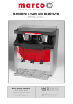
PORTABLE AIR CONDITIONER
INSTRUCTION MANUAL
Read Rules for Safe Operation and Instructions Carefully.
!
CAUTION
!
Do not leave this unit unattended in a space
where people or animals who cannot react to a
failed unit are located. A failed unit can cause
extreme overheating or death in such an
enclosed, unattended space.
2
Electrical Specifications
6. To avoid the possibility of personal injury, always
disconnect the power supply to the unit, before
installing and/or servicing.
1. All wiring must comply with local and national
electrical codes and be installed by a qualified
electrician. If you have any questions regarding
the following instructions, contact a qualified
electrician.
2. Check available power supply and resolve any
wiring problems BEFORE installation and
operation of this unit.
3. This unit draws 7.4 amps (nameplate rated)
under Cooling mode and 12.0 amps (nameplate
rated) under Heating Mode and may be used in
any properly wired, general purpose 15 amp
household grounded receptacle.
4. For your safety and protection, this unit is
grounded through the power cord plug when
plugged into a matching wall outlet. If you are
not sure whether the wall outlets in your home
are properly grounded, please consult a qualified
electrician. DO NOT USE PLUG ADAPTERS
OR EXTENSION CORDS.
5. The manufacturers nameplate is located on the
rear panel of the unit and contains electrical and
other technical data specific to this unit.
Table 1
Suggested Individual Branch Circuit
Nameplate Amps
7.4 to 12.0
AWG Wire Size
14
AWG-American Wire Gage
o
Based on copper wire at 60 C temperature rating.
Table 2
Receptacle and Fuse Types
Rated Volts
Amps
125
15
Wall Outlet
Fuse Size
Time Delay Fuse
(or circuit breaker)
Plug Type
Cooling Only Models
Heating/Cooling Models
Cooling Capacity
7200 Btu/h
7500 Btu/h
Heating Capacity
Not Applicable
1500W/1000W
52 Pints (24.6L/24Hrs)
52 Pints (24.6L/24Hrs)
Less than 54 dB(A)
Less than 54 dB(A)
115V / 60Hz
115V / 60Hz
R22
R22
5.5L(11.6Pints)
5.5L(11.6Pints)
38kg(83.7 lb.)
38kg(83.7 lb.)
Unit Specifications:
Dehumidifying Capacity
Noise Level
Power Source
Refrigerant
Water Tank Capacity
Unit Weight
Unit Dimensions(inches)W
D
Unit Dimensions(cm)W
H
D
Fan speeds
H
15 / "
18"
32 /8"
151/4"
18"
325/8"
38.7
45.6
82.9
38.7
45.6
82.9
1
4
5
3
3
Soft Touch Controls
Soft Touch Controls
Time of Day Clock
Yes
Yes
Auto - Timer
Yes
Yes
Cooling
851Watts(7.4 Amps)
851Watts(7.4 Amps)
Heating
Not Applicable
1500Watts(High) 12.0 Amps
Control Panel(llluninated)
Power Consumption:
1000Watts(Low)10.4 Amps
Dehumidifying
Fan
850W (7.4 Amps)
850W (7.4 Amps)
90W(0.8Amps)
90W(0.8Amps)
NOTE: Specifications are subject to change without notice, for further improvements.
3
Energy-Saving Tips
This appliance is designed to be highly efficient
4) Start your air conditioner before the outdoor air
in energy savings. Follow these recommendations
becomes hot and uncomfortable. This avoids an
for greater efficiency.
initial period of discomfort while the unit is
1) Select a thermostat setting that suits your
cooling off the room. Use of the automatic
start/stop programmable TIMER feature can be a
comfort needs and leave at that chosen setting.
major asset in this regard if utilized to the fullest
2) The air filter is very effcient in removing airborne
extent.
particles. Keep the air filter clean at all times.
3) Use drapes, curtains or shades to keep direct
5) When outdoor temperatures are cool enough,
sunlight form penetrating and heating room, but
turn the air conditioner off and use the FAN
do not allow drapes or curtains to obstruct the
MODE on HIGH, MED or LOW. This circulates
air flow around the unit.
indoor air, providing some cooling comfort and
utilizes less electricity.
Window Installation
The exhaust/window kit must be installed at all
Electric Shock Hazard
To avoid the possibility of personal
injury, disconnect power to the unit
before installing or servicing.
times when the unit is operating under the AIR
CONDITIONING mode.
There should be at least 11.8"(30 cm) clearance
between the unit and any other other objects or building
structure. The unit should be installed on a level
!
CAUTION
!
To avoid installation/operation difficulties,
read these instructions thorughly.
installed during operation of the remaining three
modes. (Heating/Dehumidifying/Fan).
Fig. 1 Installation Accessories
Installation Accessories Fig.1
Description
surface. The window kit does not have to be
Quantity
Drain Hose Connector
Flexible exhaust hose with adapters..........3/set
stretches from 191/2" (50cm) up to
Flexible Exhaust Hose
1
3
19 / 2" - 78 / 4"
783/4" (200cm)
Adapter
Window Exhaust
Adapter
Window exhaust adapter(flat mouth)...........1Pc
Adjustable window/patio door slider kit......2/set
from265/8" (67.5cm) up to
483/8"(203cm)
Drain hose connector.........................1 Pc
continuous drain option (hose not included)
Adapter
SPECIAL NOTE: Exterior drain hose extension
Adjustable
Window/Patio
DoorDoor
Slider
Kit Kit
Adjustable
Window/Patio
Slider
5
3
26 / 8" - 48 / 8”26 5/ - 48 3/ ”
"
8
(direct drain) is not included with this unit and can
be purchased through any local Hardware Store.
4
8
"
Window Kit Installation
Your window kit has been designed to fit most
Horizontal Window
standard "vertical"and "horizontal" window
applications. However, it may be necessary for
you to improvise/modify some aspects of the
installation procedures for certain types of
Window Slider Kit
5
Minimum: 26 /8"(67.5 cm )
3
Maximum: 48 /8"(123cm)
windows. Please refer to Fig. 2 & Fig. 2a for
minimum and maximum window openings.
Fig. 2
Water Tank Safety Feature
This unit is equipped with a fail-safe switch
mechanism which prevents the unit from condensing
water in the event the water tank is accidentally
displaced, and/or FULL with water. If this situation
occurs, the unit will signal 8 BEEPS and the
WATER FULL indicator light will flash red
Vertical
Window
continuously until the water tank is correctly
Fig. 2a
positioned and/or emptied.
NOTE: The fan motor will continue to operate
Window Slider Kit
5
Minimum: 26 /8"(67.5 cm )
3
Maximum: 48 /8"(123cm)
under this condition. This is normal, but no
cooling or dehumidifying will occur until the tank
is emptied and/or correctly installed (It may take
several minutes before the compressor resumes
normal operation).
Window Installation
Before Starting This Unit
1) Select a suitable location, making sure you have
easy access to an electrical outlet.
2) Install the Flexible Exhaust Hose and the
Adjustable Window Slider Kit as depicted in
Fig. 3
Fig. 3 & Fig. 3a.
Fig. 3a
NOTE: Step 2 is required only while using the
AIR CONDITIONER MODE
3) Plug the unit into a 115V/60Hz grounded
electrical outlet.
DO NOT USE AN EXTENSION CORD.
4) Make sure the Water Tank is correctly positioned
inside the cabinet otherwise the unit will not
operate. Fig 4.
Fig. 4
5) To turn the unit on, press the I/O key
(On/ Off Switch).
5
SWING: Allows the vertical louver grills
Key Pad Functions Fig.5
to oscillate back and forth automatically(70o Swing).
I/O: Power On/Off.
MODE: Selects the appropriate operating mode.
CLOCK: Allows you to initiate and/or change the
Cool-Heat-Dry (Dehumidifier)-Fan.
TIME OF DAY setting.
Note:"Heat Mode" is for Heating/Cooling Model
only .
I/O
MODE
FAN
ON
SWING
TIMER
OFF
MODE Indicator Lights: Illuminates under the
different mode settings Fig.6;
COOL Mode:
Green Light
HEAT Mode:
Red light
DRY(Dehumidifier)Mode:
FAN Mode:
CLOCK
Fig.5
Green Light
No indicator light
Green light while cooling
Green Light : Remains on while compressor is
operating. Green light turns off when desired
Red light while heating
temperature is achieved. Applicable to both
Green light while dehumidifying
Air Conditioner and Dehumidifier.
Cool/Heat/Dry
Red Light: Remains on while heater is
Fig.6
operating. Red light turns off when desired
temperature is achieved.
A warning signal of 8 beeps will
sound and the Water Full
indicator will flash every
0.5 seconds.
Water Full Indicator Light: Flashes red when
the water level of the water tank exceeds the
maximum set level or if the water tank is not
correctly positioned in the cabinet. Fig.7.
Water Full
FAN: Selects High-Medium-Low fan speeds
Fig.7
Fan Options:
Temperature Conversion Chart
Cooling (3 speeds) High-Medium-LOW.
Heating (2 speeds) High-Low.
O
Dry-Dehumidifying (1 speed) Medium.
O
C 10 11 12 13 14 15 16 17 18 19 20 21
F 50 52 54 55 57 59 61 63 64 66 68 70
Fan (3 speeds) High-Medium-Low.
O
C 22 23 24 25 26 27 28 29 30 31 32 33
O
F 72 73 75 77 79 81 82 84 86 88 90 91
: Used to adjust (forward ) Time of Day Clock
settings (1min, increments).
Used to adjust (forward) Temperature
settings (1oC increments).
Used to adjust (forward) Auto-Timer of settings
TIMER ON: Used to initiate the AUTO ON start time
(10 min. increments)
program, in conjuction with the
&
key pads
: Used to adjust (backward ) Time of Day Clock
settings (1min, increments).
TIMER OFF: Used to initiate the AUTO OFF stop time
Used to adjust (backward) Temperature
program, in conjuction with the
o
settings (1 C increments).
Used to adjust (backward) Auto-Timer of settings
(10 min. increments)
6
&
key pads.
Setting TIME OF DAY (Clock) Instructions:
1) Push and hold the CLOCK key pad for three(3)
l/0
12:00
seconds. The clock display will flash indicating
MODE
ON
FAN
TIMER
"12.00" for approximately 10 seconds.
SWING
OFF
CLOCK
Fig.8.
2) Push either the
or
key pad, to enter the
correct time of day. Each depression of the key pad
Fig. 8
will increase or decrease the time of day
setting (1 minute increments). Fig. 9.
l/0
12:01
3) When the correct time of day has been
MODE
ON
FAN
established in the display window, push the
TIMER
SWING
CLOCK key pad again to activate the TIME OF
OFF
CLOCK
DAY clock setting. The "colons" between the
TIME OF DAY will start to flash indicating the
Fig. 9
clock is operational.
Important Note: Any interruption to the electrical
DUCT
power supply will automatically cancel the TIME
Duct
Exhaust Air Outlet
OF DAY clock program. In the event this should
happen, you will be required to re-set the
clock program.
Fig. 10
Air Conditioner Operating Instructions
1) Install the Flexible Exhaust Hose Fig.10 and
the Adjustable Window/Patio Door Slider Kit
as depicted in Fig.2,2a & 2b (pg.5)
Water Full
TIMER
ON
MODE
COOL
12:00
l/0
MODE
ON
FAN SPEED
2) Press the I/O (on/off )key pad to switch on the
HIGH
TEMP.
Cool/Heat/Dry
TIMER
00
OFF
unit.
Green Light
Air Conditioner
3) Press the MODE key until the word COOL is
Mode
Fig. 12
displayed in the LCD (Liquid Crystal Display)
window.Fig.12. Each depression of the MODE
key will advance to a different mode setting
(Cool-Heat-Dry-Fan).
ON
MODE
COOL
FAN SPEED
or
12:00
l/0
FAN
HIGH
TEMP.
Note: Heat is for Heating/Cooling Model only.
4) Press the appropriate
TIMER
MODE
ON
TIMER
o
17 c
SWING
OFF
CLOCK
key to select a
Temperature
suitable temperature setting. The temperature
Fig. 13
selected will be indicated in the
LCD (Liquid Crystal Display) window.
Temperature settings are adjustable between
17oC(63oF)to 30oC(86oF). Fig.13.
The green indicator light will come on indicating the
air-conditioning mode is operational (there may be a
slight delay of 10-30 seconds before the cycle
begins, this is normal).
7
Air Conditioner Operating Instructions
(cont'd)
5) Press the FAN key to select the desired fan
speed setting (High-Med-Low). See Fig.14.
Your selection will be displayed in the LCD
window (each depression of the fan key will
advance to a different setting).
6) Press the SWING key to activate the automatic
air swing (oscillating )feature (the "air swing"
symbol will appear in the LCD window ). Fig. 15.
To deactivate the air swing feature, press the
SWING key again.
7) Condensed water will be accumulated in the
water tank. When the tank is full, the unit will
sound a signal (8 beeps) and the Water Full
indicator light start flashing. At this time the air
conditioning process will immediately stop
However , the fan motor will continue to operate
(this is normal ). Carefully remove the water tank
from the cabinet and dispose of the water .
Replace the water tank back to it's original
position (in cabinet) and the air conditioning
process will automatically resume. It may take
3-5 minutes for the compressor to re-start . This
is normal.
8) To adjust "air flow" direction , (up / down only )
adjust any one of the Horizontal Louver Blades
(excluding the top or bottom louver) and the
remaining louvers will automatically adjust to the
set position (excluding the top and/or bottom
louvers). Fig.16.
Cooling stops automatically when the set
temperature is achieved. Cooling resumes when the
room temperature rises above the set temperature
level. The temperature has no effect on the fan
operation. Therefore, the fan will operate
continuously (after the compressor has cycled off) to
maintain optimal temperature control.
12:00
TIMER
ON
MODE
COOL
I/O
FAN
FAN SPEED
MODE
ON
HIGH
TEMP.
00
TIMER
SWING
OFF
CLOCK
Fan Speed
Fig. 14
12:00
TIMER
TIMER
ON
MODE
MODE
COOL
FAN SPEED
I/O
FAN
MODE
ON
HIGH
SWING
TEMP.
00
TIMER
SWING
Air Swing
OFF
CLOCK
Fig. 15
Fig. 16
!
ATTENTION
!
Removal and/or partial displacement of the water
tank will cause the compressor to stop operating
(this is a safety feature). This condition will cause
the unit to "beep 8"times"and the "water full"light
will flash (red)continuously until corrected. The
compressor cannot operate during a flashing
"red" light condition. Check the following;
1. Is the water tank full?
Empty and re-install water tank.
2. Has the water tank been accidently displaced?
Re-Position water tank.
The "red" light will stop flashing automatically
When the water tank has been emptied and/or
correctly re-positioned.
!
CAUTION
!
During air conditioning and dehumidifying modes, if the
compressor cycle is interupted (unplugged, power
failure, etc.) And reinstated immediately thereafter,(within
3-5 minutes.) A "compressor protection circuit"is
automatically self-affected. The mode indicator light will
flash "green" for approximately 10 seconds, confirming the
protection circuit is activated. The compressor cannot
operate during a "compressor protecton" condition.(this is
normal)It may take 3-5 minutes before the "protection
circuit" self-deactivates.
DO NOT ATTEMPT TO START THE UNIT
(COMPRESSOR)DURING THIS PERIOD.
8
DRY (Dehumidifier ) Operating Instructions
1) Press the I/O ( on/off) key pad to switch on
the unit.
2) Press the MODE key until the word DRY
TIMER
(Dehumidifying) is displayed in the LCD display
Water Full
12:00
ON
I/O
MODE
DRY
MODE
ON
HIGH
FAN SPEED
window. Fig.17. Each depression of the MODE
TEMP.
Cool/Heat/Dry
TIMER
00
OFF
key will advance to a different mode setting
(Cool - Heat - Dry - Fan)
3) Press the appropriate
Green Light
or
Dry Mode
key to set a
Fig. 17
dehumidifying temperature between
10oC(50oF) to 30oC(86oF). Fig. 18. The green
indicator light will come on indicating the
dehumidifying mode is operational (there may be
TIMER
12:00
MODE
DRY
FAN SPEED
a slight delay of 10-30 seconds before the cycle
I/O
FAN
MODE
ON
MED
TEMP.
10 c
TIMER
SWING
OFF
CLOCK
begins, this is normal).
IMPORTANT: The temperature selected
Temperature
Fig. 18
should always be set a few degrees lower than the
room ambient temperature ,to ensure normal
dehumidifying operation. However, it is not
recommended to operate your Dehumidifier,
o
o
below temperatures of 15.5 C(60 F), this could
result in icing-up conditions of the evaporator coils,
minimizing efficiency. Under the dehumidifying
mode, you cannot select a fan speed. The fan
motor operates at a pre-set speed, which registers
as MED in the LCD window.
4) Condensed water will be accumulated in the
water tank. When the tank is full , the unit will
sound a signal(8 beeps) and the Water Full
indicator light start flashing. At this time the
dehumidification process will immediately stop.
However, the fan motor will continue to operate
(this is normal). Carefully remove the water tank
from the cabinet and dispose of the water.
Replace the water tank back to it's original
position (in cabinet) and the Dehumidifying
process will automatically resume. It may take
3-5 minutes for the compressor to re-start. This
is normal.
5) This unit also has provisions for a continuous
"drain" option (for basement applications having
a floor drain). The required drain hose extension
is not included with this unit. It can be purchased
through any local Hardware Store. Drain Hose
Specifications: Standard garden hose.
9
DRY( Dehumidifier) Operating Instructions
(cont'd)
6) To connect the continuous drain option. Remove
the water tank from the cabinet. Inside the
cabinet (water tank area) you will find a section of
hose hanging beside the water tank, which is
plugged/capped at the end. Remove the plug
from the end of the hose and install the drain
hose connector (included with this unit) into the
end of this hose section. Route the end of the
hose (with drain connection) into the water tank,
then through the hole provided in the face of the
water tank. Attach a section of Garden Hose (to
suit your continuous drain option requirements)
to the drain hose connector. Place the open end
of the hose directly over the drain area in your
basement floor. Fig.19.
IMPORTANT: Please make sure the drain hose
section routed through water tank does not interfere
with the correct positioning of the water tank inside
the cabinet, or the fail-safe switch mechanism will
be activated, not allowing the unit to operate.
7) You must remember to reverse the continuous
drain option procedure re-cap/plug the internal
drain hose and/or leave the internal drain hose
(unplugged) inside the water tank,
when re-locating your unit to a location(room)
where continuous draining is not possible.
Failure to comply with these procedures will
result in flooding.
Garden Hose
(not included)
Drain Hose Connector
!
!
CAUTION
!
During air conditioning and dehumidifying modes, if the
compressor cycle is interupted (unplugged, power
failure, etc.) And reinstated immediately thereafter,(within
3-5 minutes.) A "compressor protection circuit"is
automatically self-affected. The mode indicator light will
flash "green" for approximately 10 seconds, confirming the
protection circuit is activated. The compressor cannot
operate during a "compressor protecton" condition.(this is
normal)It may take 3-5 minutes before the "protection
circuit" self-deactivates.
DO NOT ATTEMPT TO START THE UNIT
(COMPRESSOR)DURING THIS PERIOD.
ATTENTION
Fig. 19
!
Removal and/or partial displacement of the water
tank will cause the compressor to stop operating
(this is a safety feature). This condition will cause
the unit to "beep 8"times"and the "water full"light
will flash (red)continuously until corrected. The
compressor cannot operate during a flashing
"red" light condition. Check the following;
1. Is the water tank full?
Empty and re-install water tank.
2. Has the water tank been accidently displaced?
Re-Position water tank.
The "red" light will stop flashing automatically
When the water tank has been emptied and/or
correctly re-positioned.
10
Heater Operating Instructions(For Heating/Cooling Models Only)
1) Press the MODE key until the word Heat is
displayed in the LCD window. Fig.20. Each
TIMER
depression of the MODE key will advance to a
MODE
different mode setting (Cool-Heat-Dry Fan). The
FAN SPEED
red indicator light will come on indicating the
"Heating "mode is operational (there may be a
slight delay of 5-10 seconds before the cycle
Red Light
begins, this is normal).
TIMER
MODE
ON
HEAT
TEMP.
TIMER
00
OFF
Heat Mode
Fig. 20
I/O
FAN
MODE
ON
HIGH
FAN SPEED
TEMP.
3) Press the FAN key to select the desired fan
speed setting (High-Low). Your selection will be
displayed in the LCD window. Each depression
of the fan key will alternate between the different
fan speed settings. Fig.22.
MODE
HIGH
12:00
ON
I/O
HEAT
Cool/Heat/Dry
2) Press the appropriate
or
key
to select a suitable temperature between
o
o
o
o
17 C (63 F) to 30 C (86 F). Fig.21.
12:00
ON
Water Full
25 c
TIMER
SWING
CLOCK
Temperature
Fig. 21
TIMER
MODE
4) Press the SWING key to activate the automatic
air swing (oscillating) feature, (the "air swing"
symbol will appear in the LCD window). Fig.23.
‘ press the
To deactivate the air swing feature,
SWING key again.
12:00
ON
HEAT
I/O
FAN
MODE
ON
HIGH
FAN SPEED
TEMP.
25 c
TIMER
SWING
OFF
CLOCK
Fan Speed
Fig. 22
5) To adjust"air flow" direction, (up / down only )
adjust any one of the Horizontal Louver Blades
(excluding the top or bottom louver) and the
remaining louvers will automatically adjust to the
same position. Fig.24.
Heating stops automatically when the room
temperature reaches the desired setting .The "red"
indicator mode light will close. Heating will resume
when the room temperature falls below the
established temperature setting.
TIMER
12:00
ON
MODE
FAN SPEED
SWING
Air Swing
HEAT
I/O
FAN
MODE
ON
HIGH
TEMP.
25 c
TIMER
SWING
OFF
CLOCK
Fig. 23
Fig. 24
11
Fan Operating Instructions
1) Press the I/O (on/off) key pad to switch on
the unit.
2) Press the MODE key until the word FAN is
displayed in the LCD window. Fig. 25. Each
depression of the MODE key will advance to a
different mode setting (Cool-Heat-Dry-Fan). No
indicator mode light is visible during operation of
the FAN mode (this is normal).
3) Press the FAN key to select the desired FAN
SPEED setting. Fig.26. Your selection will be
displayed in the LCD window. Each depression
of the fan key will advance to a different speed
(High-Med-Low).
MODE
I/O
Water Full
MODE
FAN SPEED
FAN
FAN
ON
HIGH
TIMER
Cool/Heat/Dry
OFF
No Light
Fan Mode
Fig. 25
I/O
MODE
FAN SPEED
FAN
FAN
MODE
ON
HIGH
TIMER
SWING
4) Press the SWING key to activate the automatic
air swing (oscillating) feature (the air swing
symbol will appear in the LCD window). Fig. 27.
To deactivate the swing feature, press the
SWING key again.
OFF
CLOCK
Fan Speed
Fig. 26
I/O
MODE
5) To adjust"air flow" direction, (up/down only)
adjust any one of the Horizontal Louver Blades
(excluding the top and bottom louver) and the
remaining louvers will automatically adjust to the
same position. Fig.28.
FAN SPEED
FAN
FAN
MODE
ON
HIGH
TIMER
SWING
Air Swing
SWING
OFF
CLOCK
Fig. 27
Fig. 28
12
Auto-Timer Instructions
NOTE: The TINE OF DAY CLOCK must be set
before the AUTO-TIMER feature will operate
The AUTO-TIMER feature offers a unique selection
of multiple choice, fully automatic on/off(start/stop)
programs between 0-23 hrs, 50 min. Under any one
mode of your Portable 4 Season Home Comfort unit.
The programs are as follows:
a) Auto-off: Pre-select a time that will turn off the
unit (automatically) at a specified time (between
0-23 hrs, 50 min.). This function must be
performed daily, (if required) as the program is
automatically canceled/erased upon completion.
b) Auto-On: Pre-select a time that will turn on the
unit (automatically) at a specified time (between
0-23 hrs, 50 min.). This function must be
performed daily, (if required) as the program is
automatically canceled/erased upon completion.
c) Auto-On & Auto-off: Pre-select a time that will
turn on and turn off the unit (automatically) at
specified times (between 0-23 hrs, 50 min.).
This program contains built-in memory. Unlike
programs a)and b) above. This program
automatically stores into memory the selected
times and will repeat daily,(same specified times)
until the program is overridden and/or canceled.
Any interruption to the electrical power supply
of the unit automatically cancels/erases all
auto timed programs. In the event this should
happen, you will be required to re-set
your program.
12:00
TIMER
ON
MODE
COOL
I/O
FAN
HIGH
FAN SPEED
TEMP.
00
MODE
ON
TIMER
SWING
OFF
Mode
Selection
Setting the AUTO-ON TIMER
Before setting the AUTO-ON timer, the TIME OF
DAY CLOCK must be set/operational. You must
also select the appropriate MODE and settings(FAN
SPEED,TEMP,SWING etc.) You will require under
the AUTO TIMED program.
1) Turn the unit"on"(I/O switch).
2) Select the appropriate MODE under which
you want the unit to operate (Cool-Heat-DryFan). Fig.29.
3) Select the appropriate FAN SPEED setting,
under which you want the unit to operate.(High,
Med,Low) (excluding Dehumidifying, as this
mode has"1" fan speed setting only ).Fig.30.
4) If you desire oscillation(auto-swing) push the
SWING key pad (the " air swing" symbol will be
displayed in the display window).Fig.31.
TIMER
MODE
CLOCK
Fig. 29
12:00
ON
COOL HEAT
I/O
FAN
MODE
ON
HIGH
FAN SPEED
TEMP.
2500c
TIMER
SWING
OFF
CLOCK
Fan Speed
Fig. 30
ON
MODE
COOL
FAN SPEED
SWING
Air Swing
13
12:00
TIMER
I/O
FAN
MODE
ON
HIGH
TEMP.
00
TIMER
SWING
OFF
CLOCK
Fig. 31
Setting the AUTO-ON TIMER(cont'd)
5) All of the settings are now registered. TURN
THE UNIT"OFF" USING THE I/O SWITCH.
6) To set the AUTO-ON timer, the unit must be
turned to the "off" position (non-operational).
7) Press the TIMER-ON key pad to initiate the
AUTO-ON time sequence. Fig. 32. The display
window will indicate TIMER-ON and the word ON
will flash for 5 seconds. Press the
or
key
to select the desired AUTO-ON start time.
Fig.32a.
Key pad will decrease the AUTO-TIMED
Setting in 10 minute increments.
Keypad will increase the AUTO-TIMED
Setting in 10 minute increments.
When the desired time is established,(the time
will flash in the display window) press the
CLOCK key pad to register the AUTO TIMERON program. The word ON will stop flashing and
remain "on" (TIMER ON)indicating the program
is set. The time of day clock setting will
immediately revert back in the display window.
IMPORTANT: The desired AUTO-ON time must
be registered within a 5 second period (after
pressing the TIMER-ON key pad) otherwise the
selected time will mot register and the system
will automatically revert back to the regular
"time of day" clock setting. If this occurs, you
must repeat step 7 again.
The unit will start automatically when the specified
AUTO-ON time is achieved on the time of day clock
(the "TIMER ON" prompt will disappear from the
display window). To cancel or override the AUTOTIMED program,simply turn on the unit before the
AUTO-ON time is scheduled to operate (the "TIMER
ON"prompt will disappear from the display window)
You can varify the AUTO-ON time selection anytime
(prior to the program starting )by pressing the
TIMER-ON key pad. The time you selected will
appear(flash)temporarily(replacing the time of day)
for approximately 5 seconds.
TIMER
ON
12:00
I/O
FAN
MODE
ON
TIMER
SWING
OFF
CLOCK
Fig. 32
TIMER
ON
12:00
I/O
FAN
MODE
ON
TIMER
SWING
OFF
CLOCK
Fig. 32a
14
Setting the AUTO-OFF TIMER
Beffor setting the AUTO-OFF timer, the time of
day clock must be set/operational.
1) To set the AUTO-OFF timer, the unit must be
turned on (I/O switch) and operational.
2) Press the TIMER-OFF key pad to initiate the
AUTO-OFF time sequence. Fig. 33. The display
window will indicate TIMER-OFF and the word
OFF will flash for 5 seconds. Press the
or
key pad to select the desired AUTO-OFF start.
Fig.33a.
Key pad will decrease the AUTO-TIMED
Setting in 10 minute increments.
Keypad will increase the AUTO-TIMED
Setting in 10 minute increments.
When the desired time is established,(the time
will flash in the display window) press the
CLOCK key pad to register the AUTO TIMEROFF program. The word OFF will stop flashing and
remain "on" (TIMER OFF)indicating the program
is set. The time of day clock setting will
immediately revert back in the display window.
You can varify the AUTO-OFF time selection
anytime by pressing the TIMER-OFF key pad. The
time you selected will appear(flash) temporarily
(replacing the time of day) for approwimately 5
seconds.
IMPORTANT: The desired AUTO-OFF time must
be registered within a 5 second period (after
pressing the TIMER-OFF key pad) otherwise the
selected time will not register and the system
will automatically revert back to the regular
"time of day" clock setting. If this occurs, you
must repeat step 2 again.
The unit will stop automatically when the specified
AUTO-OFF time is achieved on the time of day
clock. To cancal or override the AUTO-TIMED
program, simply turn off the unit manually, prior to
the scheduled AUTO-OFF time.
TIMER
OFF
12:00
I/O
FAN
MODE
ON
TIMER
SWING
OFF
CLOCK
Fig. 33
TIMER
OFF
12:00
I/O
FAN
MODE
ON
TIMER
SWING
OFF
CLOCK
Fig. 33a
15
Setting the AUTO-ON & AUTO-OFF TIMER
Before setting the AUTO-ON & AUTO-OFF Timer,
the time of day clock must be set/operational. You
must also select the appropriate operating MODE.
After the appropriate settings have been made, turn
off the unit.
1) Press the TIMER-ON key pad to initiate the
AUTO-ON time sequence.(Fig.32). The display
window will indicate TIMER-ON and the word ON
will flash for 5 seconds. Press the
or
key pad to select the desired AUTO-ON
start time.(Fig. 32a).
Key pad will decrease the AUTO-TIMED
setting in 10 minute increments.
Keypad will increase the AUTO-TIMED
setting in 10minute increments.
When the desired time is established,(the time
will flash in the display window) press the
CLOCK key pad to register the AUTO TIMERON program. The word ON will stop flashing and
remain"on" (TIMER ON) indicating the program
is set. The time of day clock setting will
immediately revert back in the display window
The unit must remain " OFF" while programming
the AUTO-OFF program.
2) Press the AUTO-OFF key pad to initiate the
AUTO-OFF time sequence. (Fig.33). The
display window will indicate TIMER-OFF and the
word OFF will flash for 5 seconds. Press the
or key pad to select the desired AUTOOFF time.(Fig. 32a).
Key pad will decrease the AUTO-TIMED
setting in 10 minute increments.
Key pad will decrease the AUTO-TIMED
setting in 10 minute increments.
When the desired time is established,(the time
will flash in the display window) press the
CLOCK key pad to register the AUTO TIMEROFF program. The word OFF will stop flashing
and remain "on" (TIMER OFF) indicating the
program is set. The time of day clock setting will
immediately revert back in the display window.
When the AUTO-ON & AUTO-OFF times are set.
Within the same program sequence, the display
window shows TIMER ON/OFF identifying that both
ON and OFF times are now programmed
(Repeatable daily until such time the program is
canceled and/or changed).
IMPORTANT: The desired AUTO-ON & AUTOOFF time must be registered within a 5 second
period (after pressing the TIMER-ON/OFF key
pads) otherwise the selected time will not
register and the system will automatically revert
back to the regular "time of day" clock setting
The unit will start automatically when the specified
AUTO-ON time is achieved on the time of day clock
and will stop automatically when the specified
AUTO-OFF time is achieved on the time of day
clock. To cancel or override the AUTO-TIMED
program, simply turn the unit on or off prior to the
scheduled AUTO-ON/OFF time. You can verify the
AUTO-ON/OFF time selection anytime by pressing
each respective TIMER-ON/TIMER-OFF key pad
and the selected time will temporarily appear
replacing the time of day clock for approximately
5 seconds.
16
Care and Maintenance
!
CAUTION
!
Before cleaning or servicing this
unit, it is recommended that the
unit be disconnected from any
electrical supply outlet
1) Do Not use gasoline, benzene, thinner or any
other chemicals to clean this unit, as these
substances may cause damage to the finish and
deformation of plastic parts.
2) Never attempt to clean the unit by pouring water
directly over any of the surface areas, as this will
cause deterioration of electrical components and
wiring insulation.
Removal and Cleaning of the Air Filter
If the air filter becomes clogged with dust/dirt, air
flow is restricted and reduces efficiency. The air
filter should be cleaned every two (2) weeks. More
frequent cleaning may be necessary depending
upon indoor air quality.
1) To remove the air filter: Grasp the air filter tab.
2) Pull the filter"out" then "up". Fig.34.
3) Dust/Dirt clogged in the filter can be removed by
vacuum cleaning the soiled areas.
4) The filter can also be washed in lukewarm soapy
water while rubbing it lightly with a brush. A mild
detergent (dishwashing soap) is recommended.
5) Rinse the filter well using clean water. Allow time
to dry before reinstalling into the unit.
6) Relace the air filter.
7) Replacement air filters are available through the
Customer Service Parts Department.
!
CAUTION
Air Filter
Tab
Fig. 34
!
Never operate the unit without the air filter
in place as this may result in damage to
the unit.
17