1
Winter
Summer
Spring
Thank you for purchasing
Fall
an American-built
product,
WARNING: This unit is equipped with an internal combustion engine and should not be used on or near any unimproved
forest-covered, brush-covered or grass-covered land unless the engine's exhaust system is equipped with a spark arrester
meeting applicable local or state laws (if any). If a spark arrester is used, it should be maintained in effective working order
by the operator.
In the State of California the above is required by law (Section 4442 of the California Public Resources Code). Other states
may have similar laws. Federal laws apply on federal lands. A spark arrester for the muffler is available through your nearest
engine authorized service dealer.
PRINTED IN U.S.A.
FORM NO. 770-7544F
DANGER:
Your unit was built to be operatedaccordingto the rules for safe operationin this manual. As with any
type of power equipment,carelessnessor error on the part of the operatorcan result in serious injury.
If you violate any of these rules, you may causeserious injury to yourself or others.
1. READTHISOWNER'S
MANUALcarefullyin its entiretybeforeattemptingto assembleor operatethis unit. Keepthis manualin
a safe placefor future and regularreferenceand for ordering
replacementparts.
2. This unitis a precisionpieceof powerequipment,nota plaything.
Thereforeexerciseextremecaution at all times.
3. Knowthe controlsand how to stop the machinequickly.
4. Donotallowchildrenunder14yearsoldto operatevehicle.Children
14 yearsandover shouldonlyoperateunit undercloseparental
supervision.Do not allowanyoneto operateit withoutproperinstruction. Onlypersonswell acquaintedwith theserules of safe
operationshouldbe allowedto useyour mower.
5. Wearsturdy,rough-soled
work shoesandclose-fittingslacksand
shirts. Do not wearloosefitting clothesor jewelry.Theycan be
caughtin movingparts. Neveroperatea unitin barefeet, sandals,
or sneakers.
6. To preventinjury, do not carry passengers
or give rides. Keep
children,petsand bystandersout ofthe areawhilemowing.Only
the operatorshould ride on the unit and only ride in the seat.
7. Checkoverheadclearancecarefullybeforedriving underpower
lines, guy wires, bridgesor low hangingtree branches,before
enteringor leavingbuildings,or in any other situationwherethe
operatormaybestruckor pulledfrom the unit,whichcould result
in seriousinjury.
8. To maintaincontrolof the unitand reducethe possibilityof upset
or collision,operatethe tractorsmoothly.Avoid erraticoperation
and excessivespeed.
9. Thoroughlyinspectthe areato be mowed. Removeall stones,
sticks, wire, bonesand otherforeign objects. Keepthe area of
operationclearof all persons,particularlysmallchildrenandpets.
Stopenginewhentheyarein the vicinityof yourmower.Although
the areaof operationshouldbe completelyclearedofforeignobjects, a small objectmayhavebeenoverlookedandcould be accidentlythrown by the mowerin any directionand causeinjury
to youor a bystander.Planyourmowingpatternto avoiddischarge
ofmaterialtowardroads,sidewalks,bystanders,petsandthelike.
10. Alwayswearsafetyglassesor eyeshieldsduringoperationorwhile
performingan adjustmentor repair,to protecteyesfrom foreign
objectsthat may be thrown from the machineIn anydirection.
11. Stop the blade(s)whencrossinggravel drives, walksor roads.
12. Disengage
all attachmentclutches,thoroughlydepressthe brake
pedal,and shift into neutral beforeattemptingto start engine.
13. Beforeleavingthe operator'sposition,disengageblade(s),place
shiftlever in neutral,engageparkingbrake, shutengineoff and
removekey.
14. Do not put handsor feetnearor underrotatingparts. Keepclear
of the dischargeopeningat all times as the rotatingblade(s)can
causeinjury.
15. Disengagepowerto attachment(s)and stop enginebeforemaking any repairsor adjustments.Disconnectthe sparkplug wire
andkeepthewire awayfrom theplugto prevent
accidental
starting.
16. Beforeattemptingto unclogthe moweror dischargechute,stop
the engine.The mowerblade(s)maycontinueto rotatefor a few
secondsaftertheengineis shutoff. Therefore,be suretheblade(s)
havestoppedcompletely.Disconnect
thesparkplugwire andkeep
the wire awayfrom the plug to preventaccidentalstarting.
17. Disengage
powerto attachment(s)
whentransporting
or notin use.
18. Foryoursafety,usetheslopegaugeincludedas partofthismanual
to measureslopesbeforeoperatingthis uniton a slopedor hilly
area. If theslopeis greaterthan150as shownon the slopegauge,
do notoperatethis uniton thatareaor seriousinjurycouldresult.
19. Donot stopor startsuddenlywhengoinguphillor downhill.Mow
up and down face of steepslopes;never acrossthe face. Use
extremecautionif it is necessary
to drivethetractorup anincline
or backthetractordownan inclinebecausethe front of the tractor could lift and rapidlyflip over backwardwhich could cause
seriousinjury.
20. Reducespeedon slopesandin sharpturns to preventtippingor
loss of control. Alwayskeepthe tractorin low gearwhengoing
downsteephillsto takeadvantage
ofenginebrakingaction.Choose
a low enoughgearso thatyouwill not haveto stop or shiftwhile
on the slope.
21. Stayalert for holesin terrainandother hiddenhazardswhichmay
causethe unit to tip over.
22. Use care whenpulling loadsor using heavyequipment.
A. Useonly approveddrawbarhitch points.
B. Limit loadsto those you can safelycontrol.
C. Do not turn sharply. Use care whenbacking.
D. Use counterweight(s)
or wheel weightswhen suggestedin
owner'smanual.
23. Watch out for traffic whencrossingor nearroadways.
24. Whenusing any attachments,neverdirectdischargeof material
towardbystanders
nor allowanyonenearvehiclewhilein operation.
25. Handlegasolinewith care. It is highlyflammable.
A. Extinguishcigarettes,cigars, pipesand all other sourcesof
ignition.
B. Use approvedgasolinecontainer.
C. Neverremovecap or add gasolineto a runningor hotengine
or fill fuel tankindoors.Allowto cool at least2 minutesbefore
refilling. Wipe up spilledgasoline.Alwaysuse original type
ventedcap.
D. Opendoors if engineis run in garage. Exhaustfumes are
dangerous.Do not run engineindoors.
26. Neverstorethe machinewithfuel in the fuel tankinsidea building
wherefumesmayreachan openflameor spark,suchas hotwater
andspaceheaters,clothesdryers,andthe like. Allowthe engine
to cool beforestoringin any enclosure.
27. To reducefire hazard,keepengineandcuttingdeckfree of grass,
leavesor excessivegreaseor oil.
28. Keepthe vehicle and attachmentsin good operatingcondition,
and keep safetydevicesin place. Use guardsas instructedin
operator'smanual.Donotoperatethis unitunlessthechutedeflector, guards,and safetyinterlocksystemare installedand functioningproperly.
29. Keep all nuts, bolts, and screws tight to be sure the equipment
is in safe working condition.
30. Thevehicleandattachments
shouldbe stoppedand inspectedfor
damageafter striking a foreign object. The damageshouldbe
repairedbeforerestartingand operatingthe equipment.
31. Do not changethe engine governorsettingsor overspeedthe
engine.
2
32. When using the vehiclewith mower, proceedas follows:
A. Mow only in daylightor in good artificiallight.
B. Nevermakea cuttingheightadjustment
whileengineisrunning
if operator must dismountto do so.
C. Shutthe engineoff andwait until the bladecomesto a complete stop beforeremovingthe grasscatcher.
D. Checkblademountingbolts for propertightnessat frequent
intervals.Also, checkbladesfor wearor damage(e.g. bent,
cracked).Replacewith bladewhich meetsoriginalequipment
specifications.
33. Checkgrasscatcherbagsfrequentlyfor wearor deterioration.For
safetyprotection,replaceonlywith newbagmeetingoriginalequipmentspecifications.
34. Look behindto makesure the area is clear beforeplacingthe
transmissionin reverseand continuelookingbehindwhile backingup. Disengage
bladesbeforeshiftinginto reverseandbacking
up.
35. This unit should not be driven up a ramp onto a trailer or truck
underpower,becausethe unitcouldtip over,causingseriouspersonalinjury. Theunit mustbepushedmanuallyto loadproperly.
36. Checkbrakeoperationfrequently.Adjustandserviceaccording
to brake adjustmentinstructionsin this manual.
37. Muffler,engine,and beltguardsbecomehotduringoperationand
can causea burn. Allow to cool down beforetouching.
This owner's manual covers two models of lawn
tractors. Follow only those instructions
which pertain to your model lawn tractor.
NOTE: Reference
unit is observed
forward.
UNPACKING
Refer to the separate deck manual for all information concerning
the deck.
1. Remove the lawn tractor from the carton as follows.
Open the top flaps. The loose parts (includes the
battery fluid, steering wheel with steering cap attached and chute deflector) may be on the seat and
wrapped in plastic, or may be located in a box.
Remove all loose parts and carton inserts. Cut the
front corners of the carton. Make certain brake is
released, use the relief valve and push the unit out
of the carton.
2. The seat has been mounted backward for shipping
purposes. If the loose parts are on the seat, carefully cut and remove the plastic wrap.
NOTE: On some units, the seat may be packed with
the loose parts. The self-tapping screws will be attached
to the seat. Remove the screws and assemble as instructed.
IMPORTANT:
This unit is shipped
WITHOUT
GASOLINE or OIL; however, a small amount of oil
may be present from the factory. Do not overfill.
After assembly, service engine with gasoline and
oil as instructed
in the separate engine manual
packed with your unit.
Self- Tapei_~g Screws
t
\
0
0
0
Seat
~
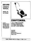
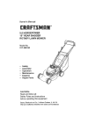
ASSEMBLINGTHE SEAT
~=-==-.-:
.-:~--~_.
~
~
r i
\
\
FIGURE 1.
/:1
~
to right or left hand side of the
from the driver's seat, facing
Remove the hex self-tapping screws which secure the
-seat to the seat pivot bracket. Turn the seat around and
place in position against the seat pivot bracket, lining
up the slotted holes in the pivot bracket with the holes
in the seat. Select desired position for the seat, and
secure with hex self-tapping screws. See figure 1.
BATTERYIt FORMATION
D. Since battery acid
any sink or drain.
trolyte containers,
solution.
E. NEVER connect or
tery while charger
WARNING
A. Battery acid must be handled with great care as
contact with it can burn and blister the skin. It is also
advisable to wear protective clothing (goggles, rubber gloves and apron) when working with it. *
is corrosive, do not pour it into
Before discarding empty elecrinse them with a neutralizing
disconnect charger clips to batis turned on as it can cause
sparks.
F. Keep all lighted materials (cigarettes, matches,
lighters) away from the battery as the hydrogen gas
generated during charging can be combustible.
G. As a further precaution, only charge the battery in
a well-ventilated area.
* Always shield eyes, protect skin and clothing
B. Should battery acid accidentally splatter into the
eyes or onto the face, rinse the affected area immediately with clean cold water. If there is any
further discomfort, seek prompt medical attention.
C. If acid spills on clothing, first dilute it with clean
water, then neutralize with a solution of ammonia/
water or baking soda/water.
when working
3
near batteries.
)~
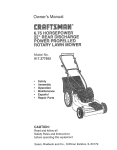
ACTIVATINGTHE BATTERY
Do not activate battery (fill with battery acid) until
battery is actually placed in service. Be certain to
read previous warnings before activating the battery.
NOTE: Some units may have the battery and battery
hardware packed with the battery fluid.
1. Lift the seat. Remove the battery cover by press-~ing
in on the sides and lifting up. See figure 2 inset. Remove the battery from the rear frame.
2. Open the battery pack. Be careful not to puncture
the box. It contains the battery fluid (acid) in a
plastic container and one short plastic tube.
3. Place the battery on a table or workbench. Make
certain the long plastic drain tube is in place on
the vent elbow.
4. Remove the six fill caps from the top of the battery with a screwdriver. Be careful not to damage
the fill caps. See figure 2.
5. Place the battery fluid container on the table or
workbench. Carefully cut off tip of the spout and
attach the short plastic tube provided. Do not
squeeze the container when cutting tip.
6. Fill each battery cell slowly and carefully to the UP~PER
LEVEL line marked on battery. See figure 3.
Use caution as the acid level will rise rapidly after
the bottom of the cell is filled.
7. Allow battery to stand for 30 minutes with the fill
caps removed, while the plates absorb acid.
8. If acid level has fallen after the 30 minute standing
period, refill each cell with battery acid to the UPPER LEVEL line on battery. Replace the fill caps.
9. Before discarding the empty container, neutralize
any residue with baking soda and rinse container
with water. Puncture container several times
before discarding.
10. Charge the battery after the 30 minute standing
period. SLOW CHARGE THE BATTERY (DO NOT
FAST CHARGE).
FIGURE 2.
\
Yo(,
FIGURE 3.
Model 704F: Charge the battery at a maximum bench
rate of 1.4 amperes until the specific gravity reading
is 1.260-1.280. Charge for a minimum of 2 hours and
a maximum of 8 hours.
Model 734G: Charge the battery at a maximum bench
rate of 2 amperes until the specific gravity reading is
1.265. Charge for a minimum of 3 hours and a
maximum of 5 hours.
NOTE: This engine is equipped with an alternator. The
current for the battery charger alternator is unregulated.
During normal operation, it is only necessary to charge
the battery:
1. When it is activated for the first time.
2. Before winter storage.
3. Before using the lawn tractor after winter storage.
NOTE-Model
704F: Charging rate after battery has
been put into operation-the
battery is to be charged
for a period of 14-16 hours. NO LONGER THAN 30
HOURS.
After battery has been charged, add only distilled
water. Do not add acid.
4
j,
""
/~
/
Battery
Drain
0\
Tube-j
INSTALLINGTHE BATTERY
Negative
Terminal
1. Raise the seat.
2. Make certain the positive cable (heavy red wire)
and negative cable (heavy black wire) are routed
outside the battery opening.
Positive
Terminal
3. Place the battery inside the opening so that the
positive terminal is toward the front of the unit. See
figure 3. Route the battery drain tube down beside
the battery.
J'r
-,'
Black
(Negative)
Cable
4. Remove the hex bolt from the positive (+) terminal.
Place the positive cable on the positive terminal.~See
figure 4. Secure with hex bolt. Be careful not
to lose the nut inside the terminal.
5. Secure the negative cable to the negative (-) terminal in the same manner. Replace the battery
cover over the positive terminal. Lower the seat.
Red
(Positive)
Cable
FIGURE 4.
Drain/""'- l
TUbeV
.on
I
6. Insert the drain tube through the cable tie which
is attached to the transaxle reinforcement bracket
the left side of the unit. Be certain drain tube
is routed away from the wheel rim. Pull on end of
cable tie to tighten (do not collapse drain tube).
Trim excess end of cable tie.
ATTACHINGTHE CHUTEDEFLECTOR
Cable
Tie
1A
Transaxle
Reinforcement
Bracket
Attach the chute deflector to the deck, following the instructions in the separate deck manual packed with
your unit.
ol
WARNING: Do not operate your unit unless
the chute deflector has been properly installed.
ATTACHINGTHE STEERINGWHEEL
FIGURE 5.
-=
r-~
,~
'":7-"
Model 704F Only:
1. Remove the hex lock nut and cupped washer from
the steering shaft, and remove the steering bellow.
Pry the steering insert off the center of the steering wheel.
~
2. Attach one end of steering bellow to the steering
wheel as shown in figure 6A, inset.
3. Position the front wheels of the tractor so they are
pointing straight forward.
4. Place the steering wheel and steering bellow over
the steering shaft, positioning steering wheel as
desired.
5. Place the washer with the cupped side down over
the steering shaft. Secure with hex lock nut. See
figure 6A.
6. Snap the steering wheel insert over the four spokes
of the steering wheel.
5
~
Model 734G Only:
tom of the steering wheel (6 o'clock position).
Model 734G is equipped with indicator lights, located
Secure with the cupped washer (cupped side
in the steering wheel. The steering wheel must beassembled down) and hex lock nut removed in step 1.
as follows for proper operation of the in-dicator
4. Place the indicator wires through the cable tie
lights.
located underneath the steering wheel insert. Con1. Remove the hex lock nut and cupped washer from
nect the wires to the same color wire leads in the
the steering shaft, and remove the steering bellow.
steering wheel insert. Tighten the cable tie to hold
Pry the sterring wheel insert off the center of the
the wires securely in position.
steering wheel.
5. Snap the steering wheel insert over the four spokes
2. The opening in the steering bellow is wider at one
of the steering wheel, making sure the indicator
end than the other. Route the five indicator wires
lights are positioned at the bottom of the steering
up through the smaller end of the steering bellow.
insert (toward the operator).
Slide steering bellow over steering shaft. Insert the
IMPORT ANT: Be certain to follow step six exactly to
five indicator wires up through the slot in the steerprevent damage to the indicator lights and wire harness
ing wheel as shown.
when using the lawn tractor.
3. Position the front wheels of the tractor so they are
6. Position the cable tie and secure the wire harness
pointing straight forward. Place the steering wheel
as follows.
over the steering shaft so the wires are at the bota. Raise the hood of the tractor, and pull excess
wire down through the dash panel.
Steering
Oil pro Clutch
sert
r
'
.r
b. Partially tighten the cable tie under the dash
panel so the cable tie is snug, but can still slide
up and down the wire harness. Slide the cable
"
tie up until it is against the dash panel.
ite
~ed
I
c. Turn the steering wheel fully in both directions
(wires will be pulled up into the steering bellow),
Brown
then
return the steering wheel to the center.
Lock
Nut;:?~~~~~
f?4S~
Carefully pull the wires down from the dash
panel, and move cable tie down the wires 1/4
inch.
~
BI.Ck~
Hex
reen
d. Tighten the cable tie securely. Trim end of cable
tie so at least one inch of the cable tie remains.
J
7. Pull bellow up against the bottom of the steering
wheel.
TIREPRESSURE
Bellow
FIGURE 68.
The tires on your unit may be over-inflated for shippingpur
Reduce the tire pressure before operating
the unit. Recommended operating tire pressure is approximately 12 p.s.i. (check sidewall of tire for tire
manufacturer's recommended pressure).
Model 734G
A
WARNING:
any
Maximum
circumstances
tire
is
pressure
30 p.s.i.
pressure should be maintained
under
Equal
tire
on all tires.
LEVELINGTHE DECK
With unit on hard, level surface, measure the distance
from the bottom edge of the center of the left side of
deck to the ground. Measure the same distance on the
center of the right side of the deck Oust behind the
chute area on side discharge units). Or, place the
blades in a straight line, and measure the distance fromthe
outside edge of the blade tips to the ground.
/'
Adjust the lift link on the left side of the deck asne
See figure 7. Recheck the adjustment.
FIGURE7.
\\'
Washer
Steering
~
6
IGNITIONSWITCH
LIGHTSWITCH
The ignition switch is located
the key to the START position
the engine is running, leave
tion. To stop the engine, turn
tion. See figure 8.
A
on the dashboard. Turn
to start the engine. When
the key in the ON posithe key to the OFF posi-
The head lamps are operated by pushing the light
switch located on the dashboard. The head lamps will
only operate when the engine is running. See figure 8.
AMMETER
The ammeter registers the rate of battery charge or
discharge. The ammeter will register on the discharging side with starting the engine. It should register on
the opposite side (charging) when the engine is running in the fast position until the battery is completely
charged. With a fully charged battery or with the engine
idling, the ammeter will not show a charge. See figure 8.
WARNING: Remove the key from the tractor when the tractor is not in use to prevent accidental starting.
THROTTLECONTROL
The throttle control is located on the left side of the
dashboard and is used to regulate the engine speed.
See figure 8. The engine should be operated from 3/4
to full throttle (FAST) when operating any equipment
that uses the tractor engine as a source of power such
as the mowing deck, snow thrower or rotary tiller.
HYDROSTATICCONTROLLEVER
The hydrostatic control lever is located on top of the
fender on the left side of the tractor. This single controllever, connected to the hydrostatic transmission,
controls both the speed and direction of the tractor. Infinite speed control is achieved by moving the control
lever forward or backward. The farther forward or
backward you move the control lever, the faster you
will travel. Pulling the control lever into neutral (N) area
will stop the tractor. See figure 9.
CHOKECONTROL
The choke control is located on the right side of the
dashboard and is operated manually. Details for the
choke operation are covered in the separate engine
manual packed with your unit. See figure 8.
Lift
Lever
Light
Switch
Control
I -
Clutch-Brake
Pedal I
I
~
Ignition
Switch
FIGURE 8A.-Model 704F
FIGURE 9.
Light
Switch
Lift
CLUTCH-BRAKEPEDAL
Throttle
The clutch-brake pedal is located on the left side of thetractor
See figure 8. Depressing the pedal returns the
drive unit to neutral (N) and applies the brake.
Control,j
l
Clutch-Brak~ 1'-..
fill
Pedal! II Y
~
I
<81
.
h
" SWltC..
1--1
PTO
NOTE: The clutch-brake pedal must be depressed
start the engine.
~
PARKINGBRAKE
To set the parking brake, depress the clutch-brakepedal,
pull up the parking brake knob and release the
clutch-brake pedal. It will stay in the raised position.
To release the parking brake, depress and release the
clutch-brake pedal. See figure 10.
Switch ~ ~
.--~
FIGURE 8B.-Model
Or~
~
to
734F
"7
NOTE: The parking brake must be set if the operator
leaves the seat with the engine running.
Parking
Brake
"""
Valve
=-,,-=
~~~
~~
CUTTINGCONTROLSA.
LIFT LEVER
Mode1704F:
The lift lever is used to raise and lower the cutting deck
and to engage and disengage the blades. Pulling it all
the way back and locking it disengages the blades.
~"'"
~1:/
NOTE: The lift lever must be in the disengaged position when starting the engine, when shifting into reverseand
if the operator leaves the seat. See figure 12.
~====-=
./
FIGURE 10.
Model 734G:The
lift lever is located on the right side of the lawn trac-tor.
It is used to raise and lower the cutting deck (which
sets the cutting height) and other attachments. Movethe
lift lever outward, select the desired cutting height
and release the lever. See figure 12.
RELIEF VALVE
A hydrostatic relief valve is provided so the unit can
be moved without the engine running. The lever which
operates the relief valve is located on the console. See
figure 10.
To operate the relief valve, place the hydrostatic control lever in neutral, release the parking brake, push
the lever forward and to the right to lock. Be certain
to release the lever by pushing it to the left before
operating the engine.
WARNING: The blade does not shut off
when the deck is raised. You must placethe
PTO switch in the OFF position.
B. DECK LIFT INDICATOR
The deck lift indicator marks the position being used
for the lift lever. Select the lift lever position desired,
press the indicator lever outward, move it to the position immediately below the lift lever and release the indicator lever. See figure 12.
INDICATOR LIGHTS (Model 734G Only)
Three indicator lights are located in the steering wheel.
If a light illuminates when attempting to start the unit,
proceed as follows.
CLUTCH-Depress
the clutch pedal.
PTO-Place
PTO switch in the OFF position.
OIL-Check
the crankcase oil level, and add oil as re-quired.
SETTING THE CUTTING HEIGHT
1. Select the position for the lift lever which gives the
desired cutting height. Move the deck lift indicator
POWER TAKE-OFF (PTO) SWITCH
so that the lift lever can be returned to the same
(Model 734G Only)
position after it is raised.
The PTO switch is located on the right side of thedashboard.
2. Move the deck wheels to the hole location so the
See figure 11. The PTO switch must be in
wheels are 1/4to 1/2 inch above the ground.
the OFF position (down) when starting the engine, when
shifting into reverse and if the operator leaves the seat.
To engage the PTO switch, pull knob out and lift up
to ON position, then release. The knob will return to
RUN position. See figure 11.
FIGURE 11.
"~ ./
~
C.
-
~\
NOTE: The PTO switch must be in OFF position when
starting the engine, when shifting into reverse and if theopera
leaves the seat.
FIGURE 12.
8
OPERA TION
1. Model 704F: Place the
ENGAGED position.
lift lever
in the
DIS-
Model 734G: Place the PTO switch in the OFF
position.
2. Depress the clutch-brake
pedal and set the park-
ing brake.
3. Place the hydrostatic control lever in the NEUTRAL
(N) position.
4. Set the throttle control in the FAST position.
5. Pullout the choke control (a warm engine may not
require choking).
6. Turn the ignition key to the right to the START position. After the engine starts, release the key. It will
return to the ON position.
NOTE: Protect the starter life by using short starting
cycles of several seconds. Cranking more than 15
seconds per minute can damage the starter motor.
GAS AND OIL FILL-UP
Service the engine with gasoline and oil as instructed
in the separate engine manual packed with your trac-tor.
Read instructions carefully.
7. Push choke knob in gradually. Move the throttle
control to desired engine speed.
STOPPINGTHE ENGINE
NOTE: Your tractor is shipped without oil; however, a
small amount of oil may be present from the factory. Do
not overfi".
Turn the ignition key to the left to the OFF position.
Remove the key to prevent accidental starting.
IMPORT ANT: If
engine. Remove
spect the unit for
before restarting
Never fill fuel tank indoors,
with engine running or while engine is hot.
Check the fluid level in the hydrostatic transmission
before initial operation. Refer to the Lubrication section on page 11.
you strike a foreign object, stop the
wire from spark plug, thoroughly inany damage, and repair the damage
and operating the mower.
NOTE: If any problems are encountered,
Trouble Shooting Chart on page 17.
refer to the
COLDWEATHERSTARTINGKIT
A cold weather starting kit is available to disengage the
drive belt to provide easier starting for the hydrostatic
transmission when the weather is cold. Order part
number 753-0509.
STARTING
THE ENGINE
IMPORT ANT: This unit is equipped with a safety interlock system for your protection. The purpose of the
safety interlock system is to prevent the engine from
cranking or starting unless the clutch-brake pedal is
depressed and the lift lever is in the disengaged position (Model 704F) or the PTO swith is in the OFF position (Model 734G). In addition, the lift lever must be in
the disengaged position (Model 704F) or the PTO
switch must be in the OFF position (Model 734G), when
the unit is put into reverse or the engine will shut off.
If the operator leaves the seat with the lift lever engaged
(Model 704F) or the PTO switch engaged (Model 734G),
and/or without setting the parking brake, the engine will
shut off.
WARNING:
OPERATINGTHE LAWN TRACTOR
1. Set the desired cutting height.
2. Start the engine as instructed
previously.
3. Move throttle control to full throttle to prevent strain
on the engine and to operate the cutting blades.
4. Depress the clutch-brake pedal so the parking
brake is released, and then release the clutchbrake pedal.
5. Place the hydrostatic control lever in either the
FORWARD or REVERSE position. The farther forward you move the hydrostatic control lever, the
faster you will travel.
WARNING: Do not operate the tractor if the
interlock
system
is malfunctioning
because it is a safety device, designed for
Look to the rear before
up.
protection.
9
back-ing
~.
,I
~
I'OiI
~.
~
/,
To stop the lawn tractor, pull the hydrostatic control
lever into NEUTRAL (N) or depress the clutch-brake
pedal.
Be sure that the lawn is clear of stones, sticks, wire,
or other objects which could damage lawn tractor or
engine. For best results and to insure more even grass
distribution, do not mow when lawn is excessively wet.
A
WARNING:
position
Before
for
any
leaving
reason,
the
Hydrostatic
Control Lever
operator's
disengage
the
~~acket
~
blades, place the hydrostatic control lever
in neutral, engage the parking brake, shut
engine off and remove the key.
When stopping the unit to empty a grass bag, etc.,
follow the instructions above. This procedure will also
eliminate "browning" the grass, which is caused by hot
exhaust gases from a running engine.
Loosen
FIGURE 13.
2. Start the engine.
3. Push the clutch-brake pedal all the way forward.
Then release the pedal completely.
The lawn tractor should not move in either direction.
If it does not move, depress the clutch-brake pedal all
the way and set the parking brake, retighten the bolt
and nut which secure the hydrostatic control lever. If
it does move, shut off the engine and adjust as follows.
4. Loosen the hex bolt which secures the pintle arm
extension to the pintle arm, using a rachet wrench
with '/2" socket extension. See figure 14.
GRASSCOLLECTOR
AVAILABLE
Grass Collector Model 190063 is available as optional
equipment for the lawn tractors shown in this manual.
A
WARNING:
The mower should
not be
operated without the entire grass catcher
or chute deflector in place.
NOTE: Under normal usage bag material is subject to
wear, and should be checked periodically. Be sure any
replacement bag complies with the mower manufacturer's recommendations. For replacement bags, use
only factory authorized replacement bag.
-~~
~wl
~rr~'
r
Pintle
Arm
WARNING: Disconnect the spark plug wire
and ground against the engine before performing any adjustments,
repairs or
~
maintenance.
~'"
SEAT ADJUSTMENT
To adjust the position of the seat, loosen the four selftapping screws on the bottom of the seat. See figure
1. Slide the seat forward or backward as desired.
Retighten the self-tapping screws.
I
C
Pintle Arm
Extension
HYDROSTATICCONTROLADJUSTMENT
The hydrostatic transmission control is in correct adjustment when the lawn tractor does not move with the
engine running, the clutch engaged and the hydrostatic
control lever in the neutral (N) position.
If adjustment
is necessary,
\Y~
~J\)'J=
,
FIGURE 14.-Top
View of Transmission
5. Raise both rear wheels off the ground by placing
blocks under the rear frame.
6. Start the engine. Make certain the clutch-brake
pedal is depressed and the parking brake is set.
follow these steps.
NOTE: A rachet wrench with a 112" socket extension
is required to make this adjustment.
1. Remove the transmission
parking brake knob and
Loosen the bolt and nut
hydrostatic control lever.
~~'-1:.n
7. Move the hydrostatic control lever to move the pintie arm until you find neutral (rear wheels do not
rotate in either direction).
panel by removing the
truss machine screws.
on the bracket on the
See figure 13.
WARNING: Be careful of the cooling
the hydrostatic transmission.
10
fan on
8. Tighten the hex bolt which secures the pintle arm
extension to the pintle arm.
9. Release the clutch-brake pedal by pushing all the
way forward, then releasing the pedal.
Check the wheels for movement. They should not rotate
in either direction. If they do, readjust until the wheels
do not move (steps 4, 7 and 8). Then adjust the position of the hydrostatic control lever as follows.
10. Depress the clutch-brake pedal all the way and set
the parking brake.
11. Shut off the engine.
12. Depress the clutch-brake pedal all the way and set
the parking brake.
13. Place the hydrostatic
CARBURETOR
ADJUSTMENTS
A
WARNING: If any adjustments
are made to
the engine while the engine is running
(e.g. carburetor),
disengage all clutches
and blades. Keep clear of all moving parts.
Be careful of heated surfaces and muffler.
Minor carburetor adjustments
may be required to
compensate
for differences
in fuel, temperature,
altitude and load. Refer to separate engine manual
for carburetor adjustment information.
NOTE: A dirty air cleaner will cause an engine to runrough.
Be certain air cleaner is clean and attached to
the carburetor before adjusting carburetor.
control lever in neutral (N).
14. Tighten the bolt and nut on the bracket on the
hydrostatic control lever.
15. Replace the transmission panel and parking brake
knob.
LUBRICA TION
WARNING:
Always
stop engine
and
disconnect spark plug wire before cleaning, lubricating or doing any kind of work
on lawn tractor.
16. Remove the blocks from under the frame, and test
the operation of the lawn tractor.
STEERINGGEARS
DECK LEVELINGADJUSTMENT
Lubricate teeth of steering gears with automotive multipurpose grease after every 25 hours of operation or
once a season. See figure 16.
If an uneven cut is obtained, the deck may be leveled
by following instructions in Assembly section.
BRAKEADJUSTMENT(See figure 15)
STEERINGSHAFT
Lubricate steering shaft at least once a season with lightoil.
The brake is located by the right rear wheel inside the
frame. During normal operation of this machine, the
brakes are subject to wear and will require periodic examination and adjustment.
A
WARNING: Do not adjust the brake while
the engine is running. Be sure to block the
wheels of the tractor before making the
brake adjustment.
To adjust the brake, remove the cotter pin. Adjust the
castle nut so the brake starts to engage when the brake
lever is 1/4" to 5/16" away from the axle housing.
NOTE: Figure 15 is shown with the unit tipped up on
rear wheels for clarity only.
11
FIGURE 16.
TRANSAXLE
The transaxle is lubricated and sealed at the factory
and does not require checking. If disassembled for any
reason, lubricate with 16 oz. of grease, part number
737-3047.
LINKAGE
Once a season lubricate all the pivot points on the
clutch, brake and lift linkage with SAE 30 engine oil.
WHEELS
The front wheels are provided with grease fittings. The
rear wheels must be removed from the axle for lubrication. Lubricate at least once a season with automotive
multi-purpose
grease.
If frequent additions are required, locate the leak andcorr
Inadequate supply of fluid may result in permanent internal damage.
PIVOTPOINTS
Lubricate all pivot points with light oil at least once a
season.
If the natural color of the transmission fluid hascha
black or milky, overheating and/or water contaminate is indicated. The fluid should be drained and
replaced with new transmission fluid.
BALL JOINTS
The ball joints and drag link ends are permanently
lubricated.
HYDROSTATICFLUID LEVEL
To drain the hydrostatic transmission, remove the hex
plug on the bottom of the hydrostatic transmission.
The transmission has been filled at. the factory and
should not require changing for the life of the
transmission.
HYDROSTATICTRANSMISSIONCOOLING
The hydrostatic transmission is cooled by the oil, fan
and fins. If the hydrostatic transmission runs hot, check
to see if the fan is in operating condition, the oil level
is correct and the fins are clean.
The transmission fluid level should be checked prior
to initial use. The level should not be above the LOWER
mark which is about 1/4" from the bottom of the expansion tank. See figure 17. Overfilling reduces the expansion area in the expansion tank and fluid will spill at
NOTE: DO NOT use high pressure water spray or steam
to clean the hydrostatic transmission.
operating temperatures.
If transmission fluid is needed, use only 1 OW3O engine
oil rated SF or CD.
MAINTENANCE
WARNING: Disconnect the spark plug wire
and ground against the engine before performing
any adjustments,
repairs
or
maintenance.
TROUBLESHOOTING
Refer to the chart on page 17 for trouble shooting
engine problems.
FIGURE 17.
ENGINE
To check or add fluid to the transmission:
Refer to the separate engine
maintenance
instructions.
1. Unscrew the parking brake knob.
for engine
Service air cleaner every 10 hours under normal conditions. Clean every few hours under extremely dusty
conditions. To service the air cleaner, refer to the
separate engine manual packed with your unit.
2. Unscrew the two screws holding the access cover
located in front of the seat.
3. Check the fluid level in the expansion tank. See
figure 17.
The spark plug(s) should be cleaned and the gap reset
once a season. Spark plug replacement is recommended at the start of each mowing season; check engine
manual for correct plug type and gap specifications.
4. If it is necessary to add fluid, unscrew the cap on
the expansion tank. The cap has left hand threads.
See figure 18. Remove the rubber bladder. Add
fluid using a funnel. Do not overfill.
5. Reassemble
manual
Maintain engine oil as instructed in the separate
engine manual packed with your unit. Read and follow
instructions
carefully.
parts.
Model 734G Only: Your engine is provided with a drain
hose for your convenience in draining oil from the
crankcase. A clamp secures the drain hose to the side
of the engine. See figure 19. To drain the oil, remove
the hose from the clamp, and remove the drain plug
from the end of the hose. Be certain to replace the drain
plug and to use the clamp to secure hose to the engine
before operating.
FIGURE 18.
12
Dimension "B" should be approximately 1/8" less than
Dimension "A." See figure 21. To increase Dimension
"B," screw tie rod into tie rod end. To decrease Dimension "B," unscrew tie rod from tie rod end. Reassemble tie rod. Check dimensions. Readjust if necessary.
A
G
Front
,t 4
FIGURE 19.-Model
(1/8"
B.
Less Than A)
.
FIGURE 21.
734G Only
FUELFILTER
CUTTINGBLADESA.
Removal for Sharpening or Replacement
~
WARNING: Be sure to disconnect
Your unit is equipped with a replaceable in-line fuel
filter. Replace filter whenever
contamination
or
discoloration
is noticed. Order replacement filter
through your authorized engine service dealer.
ground
and
the spark plug wire and remove
blade to prevent accidental engine starting. Protect hands by using heavy gloves
or a rag to grasp the cutting blades.
CLEANINGENGINEAND DECK
Any fuel or oil spilled on the machine should be wiped
off promptly. Grass, leaves, and other dirt must not be
left to accumulate around the cooling fins of the engine
or on any part of the machine.
1. Remove the large bolt and lock washer which holds
the blade and adapter to the blade spindle.
Clean the underside
2. Remove the blade and adapter from the spindle.
of the deck after each mowing.
3. If the blade or blade adapter needs replacing,
remove the two small bolts, lock washers and nuts
which hold the blade to the adapter.
WHEEL ADJUSTMENT
The caster (forward slant of the king pin) and the
camber (tilt of the wheels out at the top) require no adjustment. Automotive steering principles have been
used to determine the caster and camber on the tractor. The front wheels should toe-in 1/8 inch.
To adjust the toe-in, follow these steps.
B. Sharpening
Remove the cutting blades by following the directions
of the preceding section.
When sharpening the blades, follow the original angle
of grind as a guide. It is extremely important that each
cutting edge receives an equal amount of grinding to
prevent an unbalanced blade. An unbalanced blade will
cause excessive vibration when rotating at high speeds,
may cause damage to the mower and could break,
1. Remove the hex nut and lock washer, and drop
the end of the tie rod from the axle bracket. See
figure 20.
2. Loosen the hex jam nut on tie rod.
3. Adjust the tie rod assembly for correct toe-in.
causing personal injury.
The blade can be tested for balance by balancing it on
a round shaft screwdriver. Remove metal from the
heavy side until it balances evenly.
NOTE: It is recommended that the blade always be
removed from the adapter for the best test of balance.C.
Rod
I
Reassembly
Hex Jam
Before reassembling the blade and the blade adapter
to the unit, lubricate the spindle and the inner surface
of the blade adapter with light oil. Lubricating the bolt
holes, bolts and inner surface of the nuts with light oil
is also recommended. A 4 oz. p'lastic bottle of light oil
Nut
Hex Nut
Lock
Washer
Tie Rod
End
FIGURE
20.
13
lubricant is available, Order part number 737-0170.
Engine oil may also be used,
BATTERYREMOVALOR INSTAllATION
WARNING: When removing the battery,
follow this order of disassembly to prevent
your wrench from shorting
against thefram
When replacing blades, be sure to install the blade with
the side of the blade marked "Bottom" (or with part
number) facing the ground when the mower is in the
operating position.
Blade Mounting
Torque
1. Remove the Negative cable.
2. Remove the Positive cable.
3/8" Dia. Bolt 375 in, lb. min., 450 in. lb. max.
5/16" Dia. Bolt 150 in. lb. min., 250 in, lb. max,
To install a battery:
1. Attach the Positive cable.
2. Attach the Negative cable.
To insure safe operation of your unit, all nuts and bolts
must be checked periodically for correct tightness.
MAINTENANCEOF BATTERY
JUMP STARTING
1. Check electrolyte level periodically (at least every
two weeks). Keep the level to the split rings. Use
only distilled water or a good quality drinking water.
Never add acid or any other chemicals to the battery after initial activation.
1. Attach the first jumper cable from the Positive terminal of the good battery to the Positive terminal
of the dead battery.
2. Attach the second jumper cable from the Negative
terminal of the good battery to the FRAME OF THE
UNIT WITH THE DEAD BATTERY.
2. The battery should be checked with a hydrometer
after every 25 hours of operation. If the specific
gravity is less than 1 .225, the battery should be
recharged. For Model 704F, maximum charge rate
5 AMPS.
A
3. Coat the terminals and exposed wire with a thin
coat of grease or petroleum jelly for longer service
and protection against corrosion.
TIRES
Recommended operating tire pressure is approximately
12 p.s.i. (check sidewall of tire for tire manufacturer's
recommended pressure). Maximum tire pressure under
any circumstances is 30 p.s.i. Equal tire pressure
should be maintained on all tires.
4. The battery should be kept clean. Any deposits of
acid should be neutralized with soda and water.
Be careful not to get this solution in the cells.
5. Avoid tipping the battery. Even a "sealed"
will leak electrolyte when tipped.
WARNING: Failure to use this starting procedure could cause sparking,
and the
gases in either battery could explode.
battery
When installing a tire to the rim, be certain rim is clean
and free of rust. Lubricate both the tire and rimgen
Never inflate to over 30 p.s.i. to seat beads.
STORAGEOF THE BATTERY
1. Charge battery using normal methods. NEVER
store discharged battery as it will not recover.
WARNING: Excessive pressure (over 30p.s.
when seating beads may causetire/r
assembly to burst with force sufficient to cause serious injury.
2. When storing battery for extended periods, disconnect battery cables. Removing battery from unit is
recommended.
3. Store in cold, dry place.
DECK BELT REPLACEMENT
4. Recharge battery whenever the specific gravity is
less than 1.225, before returning to service, or
every two months, whichever occurs first.
When replacing the deck belt, disconnect the spring
from transaxle, inside the right rear wheel (step 5).
Refer to the separate deck manual packed with your
unit.
COMMONCAUSESFOR BATTERYFAILURE
1.
2.
3.
4.
5.
6.
7.
DRIVE BELT REPLACEMENT
Overcharging
Undercharging
Lack of water
Loose hold downs and/or corroded connections
Excessive loads
Battery electrolyte substitutes
Freezing of electrolyte
MODEL 704F (See Figure 22)
1. Depress the clutch pedal and set parking brake.
2. Remove the deck from the lawn tractor.
3. Raise and block the front wheels of the lawn tractor so you can work under it.
4. Remove the transmission panel, and unhook the
spring from the rear idler pulley.
NOTE: These failures do not constitute warranty.
14
5. Remove the four self-tapping screws which hold
the belt keeper assembly to the frame at the engine
pulley. Remove the belt keeper assembly.
Unplug the electric PTO.6.
Remove the torque bracket by removing two hex
bolts and washers. See figure 23.
6. Loosen both the front and rear idler pulleys.
Remove the belt from around the idler pulleys.
7. Remove the belt keeper assembly by removing the
four self-tapping screws which hold the belt keeper
assembly to the frame at the engine pulley. See
figure 23.
7. Roll the belt off of top sheave of engine pulley, onto the pulley hub.
8. Units with Cold Weather Starting Kits Installed:
Remove the rear belt guard at the transmission
pulley by removing two hex bolts, lock washers and
hex nuts.
9. Remove belt from the transmission pulley, lifting
the belt up over the fan on top of the pulley.
10. Remove belt from the engine pulley, and remove
from the unit.
Reassemble using a new belt, following instructions in
reverse order.
r aelt./Keeper
Engine
Pulley
Assembly
Self- TapPi g ,
~If- Tapping
Screws
/" Screws
~r
,
FIGURE 23.-
734G
8. Loosen the idler pulley.
around the idler pulley.
Remove the belt from
9. Roll the belt off of top sheave of engine pulley, onto
the pulley hub.
,J
10. Units with Cold Weather Starting Kits Installed:
Remove the rear belt guard at the transmission
pulley by removing two hex bolts, lock washers and
hex nuts.
11. Remove belt from the transmission pulley, lifting
the belt up over the fan on top of the pulley.
12. Remove belt from the engine pulley, and remove
from the unit.
Reassemble using a new belt, following instructions in
reverse order.
Rear'
Idler
Pulley
Belt Guard
(Cold Weather
Starting
Kit)
Unhook
-- I
..
Spring
1]
1=
Transmission
Pulley
FIGURE 22.-Model
==-
y
~
Pulley
704F
MODEL 734G (See Figures
Starting
Ki~L~
::L
--Ig~ !
2. Remove the deck from the lawn tractor.
3. Raise and block the front wheels of the lawn tractor so you can work under it.
Transmission
~r~
Pulley
4. Remove the transmission panel, and unhook the
spring from the idler pulley.
~
Spring
Belt Weather
Gua d'
(Cold
23 and 24)
1. Depress the clutch pedal and set parking brake.
5.
-Model
"Unhook
FIGURE 24.-
15
Model 734G
y
forming on essential carburetor
and fuel tanks.4.
parts, fuel lines
Refer to battery storage instructions
If the machine is to be inoperative for a period longer
than 30 days, prepare for storage as follows.
on page 14.
5. Store unit in a clean, dry area.
1. Clean the engine and the entire unit thoroughly.
2. Lubricate all lubrication points. Wipe the entire
machine with an oiled rag to protect the surfaces.
NOTE: When storing any type of power equipment in
an unventilated or metal storage shed, care should be
taken to rustproof the equipment. Using a light oil or
silicone, coat the equipment, especially any chains,
springs, bearings and cables.
3. Refer to the engine manual for correct engine
storage instructions. The engine must be completely drained of fuel to prevent gum deposits from
16
SHOOTING CHART FOR ELECTRIC START MODELS
TROUBLE
ngine will not
crank
LOOK FOR
REMEDY
Battery installed incorrectly
The battery must be installed with the negative terminal, identified at the terminal post by (Neg, N
or -). grounded. The positive terminal (Pos. P or +) attaches to the large cable from the solenoid.
The small red wire from the fuse holder or circuit breaker is also attached to the positive terminal.
Blown fuse or circuit
breaker
Replace fuse with 71/2 amp. fuse V4 x 1V4" Ig. Circuit breaker will reset itself when it cools off. Fuses
or circuit breakers seldom open or fail without a reason. The problem must be corrected. Check for
loose connections in the fuse holder. Replace fuse holder if necessary. A dead short may be in the
cranking or charging circuit where the insulation may have rubbed through and exposed the bare
wire. Replace the wire or repair with electrician's tape if the wire strands have not been damaged.
Note: Look for a wire pinched between body panels, burned by the exhaust pipe or muffler or rubbed
against a moving part.
Battery is dead or weak I
Use a hydrometer to check the condition of the battery. The Specific Gravity (s.g.) should be 1.265
at 80°F. (1.215 s.g. minimum needed for cranking engine). The reason for the battery failing must
be determined. (1) Defective battery. Battery will not accept or hold a full charge. (2) Short circuit.
Check for grounded wire. (3) Charging system not working.
The charging system is an alternator located under the flywheel. It is unregulated and rated 3 amp.
at 3600 r.p.m. A diode (rectifier) is located in the output lead just before the wire harness plug on
the engine side.
The diode changes A.C. to D.C. to charge the battery. A bad diode can either fail to charge the battery or discharge the battery if the alternator is shorted as well as the diode. To test: (1) Disconnect
charger lead from the battery (small red wire). (2) Connect 12 V small test lamp between the 3 amp.
D.C. charge lead and the positive terminal of the battery. (3) With the engine off, the lamp should
not light. If it does, the diode and possibly the alternator should be replaced. (4) Start the engine.
The lamp should light. If it does not, the alternator (stator) or lead wire is bad and should be replaced.
Engine cranks
but will not start
TROUBLE
Mechanical failure
(Wires and switches)
The interlock system includes two mechanical activated switches which are wired in series in the
circuit used to energize the starter solenoid. While testing the interlock system, you will make the
mower temporarily unsafe by permitting the engine to be started with the blade and clutch engaged.
WARNING: While testing, disengage the clutch, shut off the blade control, set the parking brake and
place the gear shift lever in neutral. Attach a wire (minimum 18 gauge) to the positive terminal of the
battery and touch the other end to the small terminal on the solenoid. If the engine does not crank: (1)
There is a loose connection or poor ground. (2) The solenoid may be bad. The solenoid can be checked
by using a heavy wire (#8 gauge minimum) and jumping between the two large terminals. If the engine
cranks, the solenoid is bad. (3) If the engine does not crank when you jump the solenoid, have the
starter motor tested by an authorized engine dealer. If the engine does crank, the problem is with
one of the safety switches, ignition switch or the wire between the fuse holder (or circuit breaker) and
the small terminal on the solenoid. Note: Look for a poor connection at the switches or a defective
switch. Replace if necessary.
Throttle or choke not in
starting position
Check owner's
No spark to spark plug
Spark plug lead disconnected.
Connect lead. Hold spark plug lead away from engine block about
1/8". Crank engine. There should be a spark. If not, have engine repaired at authorized engine service dealer.
guide for correct position
for throttle control and choke
for starting.
Faulty spark plug. To test, remove spark plug. Attach spark plug lead to spark plug. Ground the spark
plug body against the engine block. Crank the engine. The spark plug should fire at the electrode.
Replace if it does not.
17
SHOOTING CHART FOR ELECTRIC START MODELS
TROUBLE
LOOK FOR
No fuel to the carburetor!
REMEDY
Gasoline tank empty. Fill.
Fuel line or in-line fuel filter plugged. Remove and clean fuel line. Replace filter if necessary.
Air filter dirty
If the air cleaner is dirty, the engine
rRanufacturer.
Engine smokes
Engine loses crankcase
vacuum
Dipstick not seated or broken. Replace defective part.
Engine breather defective. Replace.
Excessive
vibration
Bent or damaged blade
spindle
Stop engine immediately.
Check all pulleys, blade
and damage. Tighten or replace any damaged parts.
Bent blade
Stop engine
Engine speed low
Transmission selection
Blades short or dull
Throttle must be set between 3/4 and full throttle.
Use lower transmission speed. The slower your ground
Sharpen or replace blades (uncut strip problem only).
Mower will not
discharge
grass or leaves
uncut strips
immediately.
may not start. Clean or replace as recommended
Replace damaged
adapters,
keys
blade. Only use original
and
by the engine
bolts
equipment
for tightness
blades.
speed, the better the quality of cut.
No output torque (power) in eitherdirection,
cold start.
1. Recheck relief valve position, control linkage, input drive.2.
Oil level in reservoir low.
3. Broken control shaft dowel pin. Transmission must be repaired or replaced.
Loss of output torque,
1. Operating
continuous
load.
at conditions
approaching
hydraulic stall. The transmission
fluid
has exceeded 1800 F.
2. Internal leakage due to wear. Transmission should be repaired or replaced.
3. Water in transmission fluid. Purge system of all fluid and replace with new
transmisison fluid. Replacement of the transmission is generally not necessary.
No output torque in one direction.
1. One of the directional
replaced.
2. Low oil level.
Lawn tractor cannot be pushed
with engine off.
1. Relief valve control not set.
2. Relief valve travel not adjusted.3.
Motor piston or rotor seized. Transmission
No neutral.
Oil leakage
should be repaired or
must be repaired or replaced.
Recheck linkage. Loose linkage creates an adjustment problem.
Note: The hydraulic neutral band is very narrow. Deflection in the linkage may
make it difficult to obtain neutral from both directions. It is recommended that
neutral should be positive from forward drive.
at the control shaft seal.
Noisy operation.
Output shaft rotates in the opposite
direction.
TROUBLE
valves is stuck. Transmission
1. Spillage when fluid has been added to the reservoir.
2. Spillage at the vent in the reservoir at operating temperatures due to cold
level being too high or water in the fluid. Reduce fluid level or replace fluid
in the event there is water in it (milky color).3.
Loose oil reservoir or cover.4.
Loose vent bolt.5.
Damaged control shaft seal. Transmission should be repaired.
1. Operating at part throttle. Hydrostatic transmission is designed to operate with
the engine running at full throttle.2.
Water in transmission fluid. Replace transmission fluid.
3. Air in transmission fluid. Bleed air from vent.
The transmission body is 1800 out of position. Transmission
be removed and reassembled correctly.
18
has to
For two years from the date of original retail purchase, YaRD-MaN
or replace, at its option, free of charge, F.O.B. factory or authorized
found to be defective in material or workmanship. Transportation
any power equipment unit or attachment are the responsibility of
charges for any parts submitted for replacement under this warranty
unless such return is requested by YaRD-MaN COMPANY.
COMPANY will either repair
service firm, any part or parts
charges for the movement of
the purchaser. Transportation
must be paid by the purchaser
This warranty will not apply to any part which has become inoperative due to misuse, excessive
use, accident, neglect, improper maintenance, alterations, or if the unit has not been operated
and maintained in accordance with the instructions furnished. This warranty does not apply to
the engine, Peerless components, motor, battery (except as noted below) or component partsthereof.
Please refer to the applicable manufacturer's warranty on these items.
A battery which proves defective within ninety (90) days will be replaced without charge. After
90 days but within one hundred twenty (120) days of purchase, YaRD-MaN COMPANY will replace
the defective battery for a charge of 1/2 of the current retail price of the battery in effect at the
date of return.
Warranty on units used commercially
is limited to sixty (60) days.
Warranty service is available through your local authorized service dealer or distributor. If you
do not know the dealer or distributor in your area, please write to the Customer Service Department of YaRD-MaN.
The return of a complete unit will not be accepted by the factory unless prior written permission
has been extended by YaRD-MaN.
This express limited warranty is in lieu of all other warranties, express or implied, including any
implied warranty of merchantability. The remedy of replacement is the sole and exclusive remedy
for YaRD-MaN obligations arising from the sale of its products. In no case will YaRD-MaN be
liable for incidental or consequential loss or damage.
This warranty gives you specific legal rights. You may also have other rights which vary from state
to state.
YaRD-MaN COMPANY.
P.O. BOX 360940 .CLEVELAND,
OHIO 44136
f:]
oom;-c
"0"0
~~
(/)~o
o~~
--~>-
~~"O"
0
--~-
3
~ ~
< ~
in. 5- ~
<oAI_Q.O
> §
r-Z~(QO
~O
3~=
~G'»<3~
m
~ 0 -m3 ~~~
~
(/)
~-~ -.
-Q.
Z ~ ~...
C ~-<n~
...0
(/)
Q.c
3c
0
~
n"o
-~(/)
3.Q.
m
3 3"0
~
-.~
:.<m
-~
~"O
~~
(/)Q.
~
-m
---~
mQ.Oco
Qo
0
'A
V,
(/)(/)
in'
0 ~,~
0
0 '"
-C
VO
--'A
V, Q.
(Q -.~
m
~ ~(Q
C ~
--m0 -.n
~><
~
~"O ~mn
-~,<C~
m (/) 0 (/) (/)
n~(/)
O~
~~
-~~(/)O
~
...
C ~ A.
ccj
-~
-~O n
~...
~
(/) (/)
0
CO...
n"O
~~(/)-"(/) Q.-<~
m
<~'<-~~
O-m
c
:'2!.o
Q
O~~
m
--~
-0
(/)(Qm
"O~
Q.(/)
o
--'<
~
I\)
s
~
3-
Q.
o.s:m:g<'"
"0
~
~ ~
...<
0
~(/)
~m><
---..~
(/) -(/)
-:'o-m
0
(Q
"0
-~~.~
"(/)
(/) 3 '"
0 ~
~
~ ...~
0 <
~ ~
...
-.Q. ~
~
~
...<
-.<
0
c
(/)
5"
-,(/)
~
cc'<
...n
~~o
..
<
<
>
:D
zZ
C)
--E
J
1
,
,,,
~
'..
,,
,,,
I
for future
!'
..
,
,,,
/J,
.
.
.
.
.
;';1
.
,.
---
.
.
.
:
.I
:
:
:
-GE
"
\
-:
:
:
:
:
:
.I
.A
:
:
:
:
.I
:
.A
.:
.I
:
.:I:
1
C
cn
m
-I
cn
I
I
I
I
I
I
I
I
I
I
I
I
cn II
m
m
-I
~
I:I:
I
I
I
I
cnl
I
I
I
I
~
I
~
co
0
>
c
I
I
I
I
I
1
WI
"I
I
I
I
I
I
~
0
m
1
I
I
I
I
I
I
I
I
I
-I
I
~..!j:r~~:
-
,
:
:
:
.I
.I
0
01
ml
m
:IJ
~.
r-
cn
m
-(')
I~-II
I
I>
I C
0
Z
>
~
1:
I
A
I(/)
115
I
I
I
I
:
:
.I
.I.z
:"
.0
.r-
:
reference.)
, .,,-
;',"
I
:), ,,..
,I'
, ,
'J /"1
I-. "!
-"',',
f
-4
°r-< C
<
JJ
I
I
I
0
~
"C
m -.In
~
y,
rm
0
1;A-4
r>
cn
I
<
m
:IJ
m
~
CD
m
'0
<
<:
-:I:
JJ
Z
m
JJ
~
>
I
I
I
I
I
-<
C
0
(')
<
m
JJ
0
'"T1
>
m
c:
--4
r--
C
--
~
--I
I
z
C>
r-4
II
JJ
~
-<
"0
0
(/)
m
'"T1
m
z
(')
>
g
I
I
I
t!!
I
~
I
1m
l
1"0
l
.0
.
.0
.~
:
.0
.0
."0
."'of
.-,..
.~
:&
.r-.-I
:~
.0
::b
.~
::b
',..
.(h'
:",
.~
.~
.~
.~
.~
:"
.,b
Z
I
I
I
m
0
-I
0
.-4
.-m
.:/!'
:~
:",
I
I
I
I
: :<11
0
:
"C
m
:IJ
~
I
I
I
I
I
I
I
cn
~
."
m
r-
-I
:<
m
- - - -
in a safe place
81
(Keep
-..-,
-"
(II
0
19
I
I
I
I
I
I
I