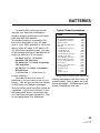
1
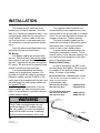
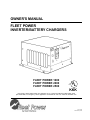
OWNER'S MANUAL
FLEET POWER
INVERTER/BATTERY CHARGERS
FLEET POWER 1000
FLEET POWER 2000
FLEET POWER 2500
C
U
®L
KKK
Fleet Power 1000 & 2000 models are certified by UL to comply with FED spec-KKK-A1822, SAE
spec-SAE-JRR1, for emergency vehicle application. All models UL and C-UL Listed for Canadian use.
90-0115-00
10/97 Fltman.pm65
INTRODUCTION
General safety information for installation
and operation is contained throughout this
manual where it applies and are not included
in this summary.
Warnings Warning statements identify conditions or practices which could result in personal
injury, loss of life, damage to equipment or
other property.
Power Source To avoid damage, operate the
equipment only within the specified AC (line)
and DC (battery) voltages.
Servicing To reduce the risk of electric shock
do not open this unit. There are no user serviceable parts inside. Refer all servicing to
qualified personnel.
Fuse Replacement For continued protection
against the possibility of fire, replace the fuse
only with a fuse of the specified voltage, current
and type rating.
The statements, specifications and instructions in this publication are believed to be correct. No warranty is made, expressed or implied by the seller or
manufacturer with respect to any results or lack thereof from the use of information in this publication and no liability is assumed for any direct or
consequential damages, personal loss or injury. All statements made herein are strictly to be used or relied on at the user's risk.
© 1997 Heart Interface Corporation. All rights reserved.
2
90-0115-00
10/97 Fltman.pm65
TABLE OF CONTENTS
Introduction . . . . . . . . . . . . . . . . . . . . . . . . . . 4
Things You Should Know . . . . . . . . . . . . . . . 5
Circuit Breaker Protection
Electronic Protection
Power Sharing
Power Switch
Remote Control Programming
Operation . . . . . . . . . . . . . . . . . . . . . . . . . . . . 6
Remote Control Panel . . . . . . . . . . . . . . . . . . 7
Remote Power Switch
System Status LEDs
DC Volts Bargraph
DC Amps Bargraph
Dip Switches
Equalize or 3-Stage Charging
Battery Type
Auto Range
Power Sharing
Dip Switch Status
Remote Control Wiring
Link 2000 Remote Control
Battery Charging . . . . . . . . . . . . . . . . . . 16
Conventional Battery Chargers
Fleet Power Battery Charger
Charging Over-Discharged Batteries
Battery Charger Voltage Table . . . . . . . . . . 21
Installation Precautions . . . . . . . . . . . . . . . 22
Installation . . . . . . . . . . . . . . . . . . . . . . . 23
Key Installation Points
Location
Grounding
Neutral Bonding
AC Wiring
Ground Fault Circuit Interrupters
Remote Control Wiring
DC Wiring
Battery Cable Fusing
Installation Options . . . . . . . . . . . . . . . . . . 29
DC Wiring Options . . . . . . . . . . . . . . . . . . . 32
Troubleshooting . . . . . . . . . . . . . . . . . . . . . .34
Status LEDs . . . . . . . . . . . . . . . . . . . . . . . . . 10
Glossary . . . . . . . . . . . . . . . . . . . . . . . . . 36
Dip Switch Programming . . . . . . . . . . 11
Specifications . . . . . . . . . . . . . . . . . . . 38
Batteries . . . . . . . . . . . . . . . . . . . . 12
Battery Types
Battery Interconnection
Battery Bank Ratings and Sizing
Warranty . . . . . . . . . . . . . . . . . . . . . . 40
3
90-0115-00
10/97 Fltman.pm65
INTRODUCTION
This owner's manual describes the
Fleet Power Inverter/Chargers from Heart
Interface. These units perform three distinct
functions:
1. DC to AC power inverting.
2. Automatic transfer switching between
inverter power and incoming AC power.
3. Automatic 3-Stage Battery charging plus
manual battery equalizing.
4. AC to DC power converter.
• The inverters provide regulated 120 Volt
AC power and crystal controlled frequency
at 60Hz from a deep cycle battery bank in
specified watts:
FP 1000-12................1000 watts
FP 2000-12................2000 watts
FP 2500-12................2500 watts
The output is a modified sinewave and
is compatible with appliances, tools and
other 120 VAC equipment. Momentary
surge power of three times the inverter
rating is available for starting electric motors. High efficiency insures the longest
possible battery life between recharges.
• The transfer switch allows the Fleet Power
Inverter/Chargers to be connected to an
external AC source and transfer the source
through to the loads. When disconnected,
the transfer switch allows automatic switching back to the inverter.
4
90-0115-00
10/97 Fltman.pm65
Fleet Power Inverter/Chargers operate
as self-contained backup power systems,
just add batteries.
• Fleet Power battery chargers are electronically controlled and rated:
FP 1000-12..................50 Amps DC
FP 2000-12................100 Amps DC
FP 2500-12................130 Amps DC
They are designed to rapidly and optimally
recharge either wet* or gel* cell deep-cycle
batteries. Battery charging is accomplished
in 3 automatic stages: Bulk Charge, Acceptance Charge and Float Charge. In addition,
using the remote control, a manually-engaged Equalizing Charge cycle is possible.
With an external AC source connected,
the Fleet Power charger also serves the
functions of a AC to DC converter to supply
all of the DC loads which are connected to
the battery.
Simple, automatic operation is made
possible by the microprocessor in the Fleet
Power Inverter/Chargers. In most cases, the
unit is left on and no attention or maintenance is required.
*Adustable with optional remote
THINGS YOU SHOULD KNOW
The optional Fleet Power Remote
Control Panel provides a power switch,
system status LEDs, DC Volts and DC Amps
LED bargraphs. On the back of the remote
is a set of dip switches which allow adjustment of the following:
• Manual Initiation of Equalize Charging
• Ambient Battery Temperature
• Battery Type
• Charger Mode (Auto or Controlled)
• Power Sharing
Circuit Breaker Protection
Fleet Power Inverter/Chargers are
circuit breaker protected.
The Fleet Power 1000 has a 12 Amp
INV/CHG circuit breaker on the front of the
unit that protects against sustained inverter
overloads over 1440 watts and the AC input
to the battery charger. The 15 Amp INPUT
circuit breaker on the unit protects the
incoming AC circuit which is transferred
through to the loads via the GFCI.
The Fleet Power 2000 has a 25 Amp
INV/CHG circuit breaker that protects
against sustained inverter overloads over
3000 watts and the AC input to the battery
charger. .
The Fleet Power 2500 has a 30 Amp
OUTPUT circuit breaker on the unit that
protects against sustained inverter overloads over 3600 watts. The 30 Amp circuit
breaker protects the incoming AC leg which
feeds the battery charger.
on the units protect the incoming AC circuit
which is transferred through to the loads
connected by the hardwire output.
The 15 Amp circuit breaker protects the
GFCI outlet on the Fleet Power 1000 and
2000 models. When a circuit breaker trips,
the circuit breaker is reset by pushing the
button back in.
Electronic Protection
Fast acting electronic circuits protect
the inverter from extreme overloads and
short circuits. Other protection includes a
low and high battery cutoff and automatic
shutdown if over temperature occurs. The
fault condition must be eliminated before
reset will occur. Example: remove overload, recharge batteries or allow to cool.
Reset by cycling the power switch OFF/ON.
Power Sharing
When connected to shorepower or
using a generator, the battery charger and
transfer functions are engaged. A unique
power sharing feature automatically reduces
the AC consumption of the battery charger
allowing necessary AC power to the load.
This prevents the circuit breaker from tripping. This feature can be adjusted using
the remote control panel. This feature is set
at the transfer rating of each unit by default.
INPUT
INV/CHG
The 30 Amp TRANSFER circuit breaker
GFCI
Fleet Power 2000 shown.
5
90-0115-00
10/97 Fltman.pm65
OPERATION
Power Switch
The Power Switch is located on the
front panel. This switch controls ON/OFF
and RESET for the inverter. Expect a 3
second delay when the power switch is
turned ON before the unit is activated.
If the unit is connected to external AC
power, the battery charger and transfer
switch will continue to function, regardless
of the position of the switch.
When external AC power is removed
and the power switch is in the ON position,
the inverter will automatically be ON. If the
switch is in the OFF position and external
AC power is removed, the inverter will be
OFF.
Inverter overload protection, transfer
switching, power sharing and battery
charger regulation will all function automatically.
If installed with the remote control
panel, the power switch on the unit should
be left in the OFF position. Refer to Remote Control Panel, page 7.
6
90-0115-00
10/97 Fltman.pm65
Power Switch
Fleet Power 1000 shown.
REMOTE CONTROL PANEL
An optional remote control panel is
available which offers several features not
found on the unit. The remote control panel
provides LED bargraphs which show system
status, battery voltage, and DC Amps in
both inverter and charge modes. These
bargraphs can also display dip switch positions and shut down conditions.
Remote Power Switch
The switch on the remote is used to
control the inverter and can also be used to
control the battery charger function. When
a remote control is used, the power switch
on the inverter should be left in the OFF
position.
System Status LEDs
These 4 LEDs monitor the system as
described in the table on page 10.
DC Volts Bargraph
These LEDs indicate battery voltage as
measured inside the unit. Each LED segment indicates .5 Volts. If an overload
occurs and the unit shuts down, the DC
Volts bargraph will stop indicating battery
voltage and display the dip switch settings.
It will return to indicating battery voltage
only after the unit has been reset.
DC Amps Bargraph
These LEDs approximate DC input
current in inverter mode and DC output
current in battery charger mode. Two
ranges are used -- below 50 Amps each
segment represents a 10 Amp increment,
above 50 Amps each segment represents a
20 Amp increment. Above 130 Amps, a
flashing LED segment indicates the value
displayed plus 100 Amps (flashing 50 LED
is equal to 50 + 100 or 150 Amps DC).
If a shutdown occurs, the DC Amps
bargraph will stop indicating DC Amps and
will indicate the type of problem . Each LED
segment indicates a different problem as
described in the troubleshooting section on
page 34.
7
90-0115-00
10/97 Fltman.pm65
REMOTE CONTROL PANEL
Dip Switches
On the back of the Fleet Power remote
control panel is a set of 8 dip switches
which are used to make several adjustments. On the switch block, each switch is
numbered . . .1 through 8 and the ON position is indicated. The switch settings can be
changed at any time, even while the unit is
operating. Following is a discussion of
each adjustment. Refer to the table on
page 11 for dip switch programming.
The battery LED blinks when equalizing. See page 18 for a discussion of the
theory and procedure for battery equalizing.
SWITCH #2 & #3 - Battery Type Gel cell
and wet cell batteries have slightly different
charge voltage requirements. Optimum
battery charging is temperature dependent.
For these reasons, the dip switches allow
four different battery charger voltage set
points, depending on battery type and
ambient temperature:
Cool Wet Cell
Warm Wet Cell
Cool Gel Cell
Warm Gel Cell
BACK VIEW
Fleet Power Remote Control Panel
SWITCH 1 - Manual Equalizing Cycling this switch ON for 1 second, then OFF,
will initiate an equalizing charge cycle. The
battery charger must be engaged before
cycling the switch. The dip switch must
always be returned to the OFF position.
If it is left ON, an equalizing charge cycle
will initiate every time the charger is
engaged - this could cause battery damage.
The equalizing cycle is timed to last 8
hours from the time the switch is cycled, at
which point the charger resumes normal
charging in the float stage.
8
90-0115-00
10/97 Fltman.pm65
< 80 degrees F.
> 80 degrees F.
< 80 degrees F.
> 80 degrees F.
Refer to the table on page 21 for the
specific voltages for each setting.
SWITCH #4 - Auto Charge With the switch
in the OFF position, the remote panel ON/
OFF switch only controls the inverter operation. With the switch turned ON, it allows
the power ON/OFF switch on the front of the
remote to control the battery charger as well
as the inverter.
SWITCH #5 & #6 - Not used for adjustments.
SWITCH #7 & #8 - Power Sharing These
switches should be set to match the value of
the circuit breaker which protects the incoming AC power. They may also limit the
output current from the battery charger.
REMOTE CONTROL PANEL
Use the 5 Amp setting for small generators, or for charging deeply discharged
batteries.
Dip Switch Status
You can check the position of the dip
switches by quickly cycling the power switch
OFF/ON twice. The DC Volts bargraph will
cease to display battery voltage and will
indicate the settings of each dip switch. In
this mode the bottom LED will illuminate if
switch 1 is on; the second LED will illuminate if switch 2 is on, etc. Dip switch settings are indicated for 10 seconds after
which time the display returns to indicating
battery voltage.
Factory default settings for all dip
switches are in the Off position.
Remote Control Wiring
The remote control panel is supplied
with 25 or 50 ft. of telephone cable. The
cable supplied may be 6 conductor, however, only 4 conductor is required. You may
buy standard 4 conductor telephone cable
and run up to 50 ft., if desired. Use only a
single length of telephone wire, do not
splice.
Refer to page 11 for the Dip Switch
Programming chart.
9
90-0115-00
10/97 Fltman.pm65
STATUS LEDs
Status LED
Purpose
Power on light. It will be illuminated whenever the
INV/CHRG
power switch is on (inverter on) or when there is
(Inverter/Charg
incoming AC power and the charger comes on.
AC Input
Illuminates when incoming AC power has been
applied and the transfer relays have engaged.
There is a 7-12 second delay from the time the AC
is applied and this LED illuminates.
Steady
Overload
Indicates an over-temperature condition, the unit is
shut down. It will reset automatically after cooling.
Blinking
Overload
Inverter mode- Shutdown, diagnose problem using
DC Amps bar graph. Charger mode- Thermal
shutdown, after cooling reset by cycling power
switch.
This is a High/Low Battery warning condition.
Steady Battery Inverter mode: Battery > 15.25 or < 10.50 volts
Charger mode: Battery > 15.25 or < 10.00 volts
Blinking
Battery
10
90-0115-00
10/97 Fltman.pm65
Indicates either a shutdown or equalizing.
Battery > 15.50 volts, will auto-reset at 15.25.
Inverter mode: Battery < 10.00 volts, will auto reset
at charger float voltage or upon AC input.
Charger mode: Battery < 8.00 volts for 1 minute,
remove all DC loads and manually reset by cycling
disconnecting
and reapplying shorepower.
the
power switch.
DIP SWITCH PROGRAMMING
Feature
Switch
Number
Set Point
1
Equalize or
3 Stage
Charging
Toggle
On/Off
Equalize (Do not leave on.)
Off
Battery
Type
3 Stage Charging*
2
3
On
On
Warm Gel Cell
(>80 deg. F.)
Off
On
Cool Gel Cell
(<80 deg. F.)
On
Off
Warm Wet Cell (>80 deg. F.)
Off
Off
Cool Wet Cell
(<80 deg. F.)*
4
Auto
Charge
Power
Sharing
On
Disable: Charger responds to On/Off
switch.
Off
Enable: Charger on when AC
connected.*
5
6
Not used.
7
8
1000
On
On
2.5 Amps
Off
On
On
Off
2000
5 Amps
2500
5 Amps
5 Amps
15 Amps
20 Amps
Off
10 Amps
20 Amps
30 Amps
Off
15 Amps*
30 Amps*
Disabled*
*indicates factory default setting.
11
90-0115-00
10/97 Fltman.pm65
BATTERIES
BATTERY TYPES
Use only deep-cycle batteries with your
Fleet Power Inverter/Charger. These fall
into two broad categories, wet cell and gel
cell.
Wet Cell Batteries
True deep-cycle wet cell batteries are
characterized by relatively thick plates that
are alloyed with antimony.
Common marine/RV deep-cycle
batteries are acceptable. However, golf
cart batteries have better performance and
life. They are 6 Volt batteries that must be
used in series pairs. High quality marine
deep-cycle batteries offer good performance and are available in a wide variety
of sizes. Floor sweeper, fork lift or large 2
Volt cells can also offer excellent performance, if their large size can be accommodated.
12
90-0115-00
10/97 Fltman.pm65
It should be noted that high antimony
deep-cycle batteries will give off gas as a
natural result of charging and will experience some water loss. It is very important
that the electrolyte level be checked
frequently and topped off with distilled
water when necessary. Never allow the
tops of the plates to be exposed to air, as
contamination of the cell will result. Keeping the tops of batteries clean will reduce
self-discharging. Always provide ventilation
for the battery storage compartment.
Do not use car batteries or engine
starting batteries of any kind with your
inverter/charger. Beware of any battery that
is rated in Cold Cranking Amps (CCA). This
is a rating which applies only to engine
starting batteries. In general, most wet cell
batteries that are described as hybrid batteries, suitable for either engine starting or
deep-cycle applications, are a compromise
and will give limited life if deeply discharged.
Beware of 8-D starting batteries that
are commonly used for starting diesel engines. These batteries are not deep-cycle.
BATTERIES
Beware of so-called maintenancefree batteries. These batteries have calcium alloyed with the lead and hold the
liquid electrolyte in a sponge-like material.
They are sealed and water cannot be
added. Do no confuse them with true gel
cell batteries, they will not hold up to deep
discharging.
Gel Cell Batteries
Gel cell batteries are lead-acid batteries similar in many ways to the common wet
cell battery, but differences in the chemistry
and construction provide some unique
features.
No Maintenance - There is no need to
add water and the tops of the batteries stay
clean. Also, the batteries can be used in
any position and may be used without a
battery box.
Low Self-Discharging - Unlike wet cell
batteries, the gel cell will hold its charge for
months if left sitting with no load and no
float charge. They can be stored without a
constant float charge and without fear of
freezing.
Low Internal Resistance - The result
of low internal resistance is a higher battery
voltage under load, which will result in
better inverter performance on demanding
high power loads. In addition, this allows
the gel cell to accept a high rate of charge,
a plus for rapid recharging.
The features of the gel cell batteries
solve many common problems. Cycle life is
high, even under constant deep discharging.
BATTERY INTERCONNECTION
In most cases you will be using a bank
of two or more batteries with your inverter/
charger. You may connect batteries together in two configurations, series and
parallel.
Series
Connecting 2 batteries in series will
double the voltage of the battery bank. For
instance, two 6 Volt batteries connected in
series will produce 12 Volts. The Amp-hour
capacity of the battery bank will be the
same as each individual battery. Example,
two 6 Volt 220 Amp-hour batteries in series
will produce on 12 Volt 220 Amp-hour battery bank.
-
+
+
Series
13
90-0115-00
10/97 Fltman.pm65
BATTERIES
Parallel
Connecting 2 batteries in parallel will
double the Amp-hour rating of the battery
bank, while the voltage will be the same as
each individual battery. Example, two 12
Volt 105 Amp-hour batteries in parallel will
produce one 12 Volt 210 Amp-hour battery
bank.
+
+
Parallel
Only similar batteries should be
connected together in one bank. Do not
connect old and new batteries together or
wet and gel cell batteries together. In the
above drawing, the load is connected to the
positive terminal of the first battery and the
negative terminal of the last battery. This
practice helps to balance the battery bank
and is called cross connecting the battery
bank.
14
90-0115-00
10/97 Fltman.pm65
Always use proper terminals for your
interconnecting battery cables which are
appropriate to handle the current.
Battery Bank Ratings and Sizing
Deep-cycle batteries are usually rated
in Amp-hours. The Amp-hour rating is
based on a 20 hour discharge cycle, therefore, a 100 Amp-hour battery can deliver 5
Amps for 20 hours. If the discharge rate is
greater than 5 Amps, the available Amphours are decreased. If the load is increased to 100 Amps, only about 45 Amphours will be available at this rate of discharge.
Another common rating is reserve
capacity expressed in minutes. This is
derived by placing a 25 Amp load on the
battery and measuring the time until the
battery voltage reaches 10.5 Volts.
Deep-cycle batteries can be discharged
about 80% before permanent damage
occurs, though shallower cycling will result
in much longer battery life. 50% cycling is
generally considered to be a good compromise between long battery life and a reasonably sized battery bank.
BATTERIES
To achieve 50% cycling you should
calculate your Amp-hour consumption
between charging cycles and use a battery
bank with twice that capacity.
To calculate Amp-hour consumption first
look at the rating plate on your AC appliance or tools. Each appliance or tool will be
rated in either AC Amps or AC watts or AC
VA (Volts-Amps) apparent power. Use one
of the following formulas to calculate the DC
Amp-hour draw for a 12 Volt system:
(AC Amps x 10) x 1.1 x hours of
operation = DC Amp-hours
(AC watts/12) x 1.1 x hours of operation
= DC Amp-hours
(AC VA/12) x 1.1 x hours of operation =
DC Amp-hours
In all formulas, 1.1 is the factor for
inverter efficiency.
Calculate the above for every AC
appliance or tool you intend to use on your
inverter. This will give you the total number
of Amp-hours used between recharges.
Size your battery bank using this number as
a guideline. A good rule to follow is to size
the battery bank about 2 times larger than
your total Amp-hour load requirement. Plan
on recharging when 50% discharged.
Typical PowerConsumption
Loads
On-Board Computers
Quartz Halogen Flood
0.2 HP Bench Grinder
Hammer Drill
3/8" Electric Drill Motor
Sawzall
0.5 HP Bench Grinder
1.0 HP Tile Saw
0.5 HP Skil® Saw
2.0 HP Radial Arm Saw
2.5 HP Chain Saw
Hand Blower/Vacuum
Quartz Halogen Flood
11 gal. Air Compressor
Chain Saw
20 gal. Air Compressor
10" Table Saw
10" Miter Saw
Planer
Coring System
Watts
200
300
300
500
500
500
750
800
1200
1200
1200
1450
1500
1600
1700
1800
1800
1800
1800
2000
Many electric motors have momentary
starting requirements well above their operational rating. Start up watts are listed
where appropriate. Individual styles and
brands of appliances may vary.
15
90-0115-00
10/97 Fltman.pm65
BATTERY CHARGING
Battery Charging
Completely recharging wet cell deepcycle batteries requires the battery voltage
to be raised beyond what is known as the
gassing point. This is the voltage at which
the battery begins to bubble and gas is
given off. If charging stops short of this
point, sulfate is left on the plates and deterioration of the battery begins. The gassing
point will vary with battery temperature.
Gel cell batteries must not be charged
to their gassing point. In fact, high voltage
charging which gasses these batteries is
harmful to them. They typically require a
lower bulk charge voltage and a higher float
voltage. Consult the battery manufacturer
for specifications.
Conventional Battery Chargers
Most conventional battery chargers are
single-stage constant voltage chargers.
They must stop short of the gassing point or
they will overcharge the battery bank.
Therefore, most 12 volt battery chargers
bring the battery voltage up to about 13.8
Volts.
16
90-0115-00
10/97 Fltman.pm65
This presents two problems. First,
since the battery voltage does not reach the
gassing point, sulfate is left on the plates.
Second, 13.8 volts is close enough to the
gassing point that some gas will escape,
and the wet cell battery will need to be
frequently topped off with distilled water.
Conventional battery chargers also
suffer from another inherent characteristic of
design, which is a tapering output. While
they will deliver their rated current into a
deeply discharged battery, as the battery
becomes charged and the voltage rises, the
output current of the charger tapers down.
This taper continues as the battery is
charged, taking a very long time to reach an
acceptable recharge.
Fleet Power Battery Chargers
Fleet Power battery chargers are designed to overcome the limitations of conventional chargers by utilizing 3 distinct
stages, each designed for optimal recharging of both wet cell and gel cell deep-cycle
batteries.
BATTERY CHARGING
NOTE: Fleet Power battery chargers are on
whenever there is AC power connected to
the charger input, regardless of the condition of the On/Off switch. This feature can
be disabled by setting the dip switch #4
(back of the remote) to "On" so that the
charger will also be controlled by the On/Off
switch.
Each time the battery charger is engaged, the 3 stages proceed automatically,
resulting in an efficient, complete recharge
and safe battery maintenance. Use of the
remote control provides the ability to periodically apply an 8-hour timed equalizing
charge.
The battery charger stages are:
Stage 1 - Bulk Charge During the bulk
charge stage most of the charge current is
delivered to the battery bank. This phase is
engaged as soon as the battery charger is
activated. Full rated charger current is
delivered to the battery bank until the bulk
charge voltage limit is reached. This results
in a relatively rapid recharge.
Generally, a wet cell battery bank
should not be charged up to the gassing
point at a rate which exceeds 25% of its
capacity. In other words, a 12 volt battery
bank of 520 Amp-hours should not be
charged at over 130 Amps.
17
90-0115-00
10/97 Fltman.pm65
BATTERY CHARGING
Gel cell batteries can accept a higher
rate of charge. Consult the manufacturer for
specifications.
Stage 2 - Acceptance Charge The
acceptance stage immediately follows the
bulk charge stage. During this stage the
battery voltage is held constant at the bulk
charge voltage limit and the current gradually ramps down. During this stage the
battery is accepting its final amount of
charge current and the last of the sulfate on
the plates is removed.
The acceptance stage lasts until the
charge current reaches about 6-7 Amps. A
timer will terminate the acceptance stage if
this current level is not reached. This timer
is set automatically when the dip switches
for battery type are set. Maximum acceptance time is 1 hour for wet cells and 3
hours for gel cells. Gel cell acceptance time
can be increased because the battery is not
gassing. Expect wet cell batteries to gas
somewhat during acceptance, this is a
necessary part of the charging process.
Stage 3 - Float Charge When the
acceptance stage is terminated, either
because the charge current ramped down to
6-7 Amps or the timer engaged, battery
charger current will shut off. The unit monitors the battery voltage while it drifts down
from the bulk charge voltage limit. When it
reaches the float voltage set point, the float
charge stage is engaged.
18
90-0115-00
10/97 Fltman.pm65
The float charge stage holds the battery
voltage at a lower level, where it is safe for
long term battery maintenance. During the
float charge stage, the full output current of
the battery charger is available to operate
any DC appliances that may be on the
system, while constantly maintaining the
float charge voltage.
The battery charger remains in the float
charge stage indefinitely until the charger is
disconnected from incoming AC power.
Stage 4 - Equalizing Charge This is
the only battery charger stage which is not
engaged automatically. It must be manually
initiated each time it is necessary to equalize using a dip switch on the back of the
remote control. Applying an equalizing
charge is not possible without the use of a
remote.
Periodic equalizing is recommended by
most wet cell deep-cycle battery manufacturers. There are no firm rules for how often
an equalizing charge should be applied, but
once a month is a good rule of thumb for
batteries which are regularly cycled, less
often for systems in only occasional use.
The equalizing charge is a timed, 8hour cycle. If desired, it can be ended by
interrupting the AC power to the charger at
any time during the cycle. Equalizing
should be engaged after the batteries have
been fully charged by a normal battery
BATTERY CHARGING
charging cycle. The battery voltage will
increase to 16.3 using the cool temperature
wet cell setting. This will cause the battery
bank to gas profusely and will accomplish
the following:
1. Removal of residual sulfate. Each time
a battery is cycled (discharged and recharged), a small amount of sulfate is left on
the plates. Over time, this gradual build-up
of sulfate will compromise the performance
of the battery. By applying an equalizing
charge, the sulfate is returned back to the
electrolyte, raising the specific gravity and
fully exposing the active material of the
plates.
2. Bring all cells to the same potential.
All lead-acid batteries are made up of individual 2 Volt cells. As the battery bank is
cycled, slight differences in the cells result
in different cell voltages, affecting the overall charge effectiveness. Equalizing brings
all cells up to the same voltage and the
electrolyte in each cell to the same specific
gravity.
3. Mixing up of the electrolyte. Electrolyte in battery cells tend to separate into
layers of acid and water. The vigorous
boiling action of the battery during equalizing serves to physically mix the electrolyte.
Equalizing is not required on gel cell
batteries. You will note that if the dip
switches are set in one of the two gel cell
positions, the equalizing charge voltage is
the same as the bulk charge voltage, therefore, equalizing is equivalent to an 8-hour
acceptance stage and is not harmful.
To limit the DC current during equalizing to less than 15 Amps, turn on dip
switches 7 and 8 before starting the equalize charge. Do not operate AC loads that
are on the output of the inverter/charger
when equalizing.
Charging Over-Discharged Batteries
Charging into a battery bank with a
terminal voltage of less than 8 Volts presents a special problem for the unit. If this
situation arises, the unit will attempt to
charge for 1 minute. If the inverter senses
excessive ripple voltage, it will shut down to
protect itself.
To successfully charge an overdischarged battery, you must remove as
much DC load as possible. Set dip
switches 7 and 8 to the ON position to limit
the amount of charge current and the resulting ripple voltage. After the battery voltage
has reached 10 Volts, these switches can
be set to their previous positions.
19
90-0115-00
10/97 Fltman.pm65
BATTERY CHARGING
WARNINGS
1. Do not equalize gel cell batteries
with the remote programmed for wet
cells.
2. Always monitor the equalize
charge. Provide proper ventilation for
battery fumes. Do not allow any sparks
during equalizing. If one or more cells
begin to overflow, terminate the equalize
charge.
3. Check and top off the battery electrolyte both before and after the
equalizing charge. Do not expose the
battery plates to air. Leave the battery
caps on while equalizing.
4. Remove all loads from the DC system before equalizing. Some DC loads
may not tolerate the high charge voltage.
5. Do not leave the equalize dip
switch in the ON position. It must be
cycled OFF and left in the OFF position.
If left ON, the unit will engage the equalizing cycle every time the battery charger
is engaged.
20
90-0115-00
10/97 Fltman.pm65
Note: If a continuous DC load in excess of the charge rate is placed on the
battery bank, eventually the battery voltage
will drop below 8 Volts and the battery
charger will shut off. This load must be
significantly reduced and the power to the
charger cycled to resume charging.
Blinking of the battery LED on the
remote control while charging is a warning
that an over-discharge is imminent and that
the DC load should be reduced.
NOTE: Equalize only after a regular
charge cycle.
BATTERY CHARGER VOLTAGE SETTINGS
B at t er y Ty p e an d
Temp er at u r e
B u lk Vo lt ag e/
Max T ime
Flo at
Vo lt ag e
Eq u alize
Vo lt ag e
12 Volt Wet Cell
Warm Temperature
14.0 / 1 hr
13.1
15.8
12 Volt Wet Cell
Cool Temperature
14.4 / 1 hr
13.5
16.3
12 Volt Gel Cell
Warm Temperature
13.8 / 3 hr
13.3
13.8
12 Volt Gel Cell
Cool Temperature
14.1 / 3 hr
13.6
14.1
21
90-0115-00
10/97 Fltman.pm65
INSTALLATION PRECAUTIONS
CAUTION This equipment is not ignition protected and employs components that tend to produce arcs or
sparks. To reduce the risk of fire or
explosions, do not install in compartments containing batteries or flammable materials or areas in which
ignition-protected equipment is required.
WARNING
For continued protection against risk of
electric shock, use only the groundfault circuit interrupter (GFCI) type
receptacles detailed in this owner's
manual. Other types may fail to operate
properly when connected to this inverter,
resulting in a potential shock hazard.
CAUTION To reduce the risk of electric
shock and prevent premature failure due to
corrosion, do not mount where exposed
to rain or spray.
CAUTION To prevent fire, do not obstruct
ventilation openings. Do not mount in a
zero clearance compartment, overheating
may result.
NOTICE The output of this device is not
sinusoidal. It has a maximum total harmonic distortion of 47% and a maximum
single harmonic of 34%.
22
90-0115-00
10/97 Fltman.pm65
CAUTION Risk of electrical shock. Both
AC & DC voltage sources are terminated
inside this equipment. Each circuit must
be individually opened before servicing.
CAUTION Risk of electrical shock. Do
not remove cover, no user serviceable
parts inside. Refer servicing to qualified
service personnel.
APPLICATION INFORMATION Provided
with integral electronic protection
against AC & DC overloads.
AC Inputs
AC Output
Remote
Jack
Chassis
Ground
Lug
Fleet Power 2500 shown.
INSTALLATION
Key Installation Points
The Power Switch must be turned OFF
before you begin.
1. Observe proper polarity when
connecting batteries. Reverse DC polarity
will result in damage to the unit and will void
the warranty. Use care when making the
DC connections.
2. Do not back-feed the AC output of
the inverter with incoming AC power. A
back-feed occurs when AC power from
shore power or generator is connected to
the output of the inverter. This will damage
the inverter and void the warranty. Remember that incoming AC must be fed only to
the AC input and never to the AC output.
Always check for AC voltage before connecting wires to the AC output. Do NOT
turn the inverter ON until all AC connections
have been made. Back-feeding the inverter
voids the warranty.
3. Do not connect the AC input to the
AC output. In effect, this would be plugging the battery charger into the inverter.
This could occur if the unit is connected to
the entire leg of a circuit breaker panel, then
a circuit breaker on that leg is used to feed
the battery charger. This will cause the unit
to oscillate ON and OFF when the unit is in
inverter mode.
4. Always use proper wire and connectors. The proper battery cable size is
critical because considerable amperage
flows in the DC circuit. Fusing the positive
DC cable is required. The AC wire size is
dependant on potential current in the circuit.
Consult the NEC (National Electric Code)
for proper wire gauge.
5. Keep the inverter/charger out of
the elements and out of direct contact
with water or spray. Remember that the
unit is a piece of electronic equipment and
treat it accordingly.
6. Mount the unit as close to the
batteries as possible but not in the presence of flammable fumes or in an enclosed
battery compartment.
7. The connectors for the remote
control and the chassis ground bonding
lug, as well as for the AC wires, are located on the bottom of the unit. Be sure
to make these connections before bolting
the unit down.
8. You may mount the unit horizontally (on a shelf) or vertically (on a wall or
bulkhead). If mounted vertically, you must
orient the unit so the switch and the circuit
breakers are facing up and the fan and
battery cables are facing down.
9. Allow several inches of clearance
around the unit and allow for a supply of
fresh air to the cooling fan. Do not block
any of the vents or louvers. The fan pulls
air from outside the unit. It blows air across
the internal components, particularly the
transformer and heat sinks, then out the
side vents.
23
90-0115-00
10/97 Fltman.pm65
INSTALLATION
10. If installing in a system which includes an existing battery charger or converter, make sure these do not operate
from the inverter output AC power. This
sets up a power loop which, due to inefficiencies, will quickly drain the batteries.
11. Make sure all wiring conforms to
local and national electrical codes. If in
doubt, consult with a qualified electrician.
12. Keep the overall length of each
battery cable less than 10 feet. If needed,
attach short extension cables. Do not use
frame ground or a ground bonding system
as a current carrying conductor. Run the
negative cable directly to the battery bank.
If the positive and negative cables run
parallel to each other, twist the cables
together. This will minimize the adverse
effects of inductance.
13. To meet electrical codes, a fuse
must be installed in the positive battery
cable within 18 inches of the battery post.
This fuse is intended to protect the battery
and cables against a dead short circuit.
The inverter is protected internally and will
not blow a properly sized fuse.
14. DC wiring is generally very simple,
the positive and negative cables from the
inverter/charger are connected to the house
or auxiliary battery. In the case of multiple
batteries the interconnecting jumper cables
must be of the same AWG as those supplied with the inverter/charger.
24
90-0115-00
10/97 Fltman.pm65
15. If multiple battery banks are to be
charged, a battery selector switch can be
installed, allowing the banks to be charged
either individually or simultaneously. A
solenoid can also be used.
WARNING
Do not mount the unit in an enclosed
battery compartment. Take precautions
to keep road dirt and spray off the unit.
Grounding
For safety purposes, the chassis of
the inverter/charger must be connected
to your AC ground system. The chassis
ground bonding lug is located on the bottom
of the unit. This connector can accept two
wires, the first is used to connect the unit to
AC ground, the second can be used to
connect other AC equipment to ground.
Use bare copper insulated wire, solid or
stranded. Strip one end and use a screwdriver to secure it to the chassis ground
bonding lug. This wire will connect to the
ground in your AC electrical system, typically the vehicle chassis. Make sure the
connection is clean and tight.
INSTALLATION
This procedure will connect the chassis
of your unit to AC ground. In addition, the
AC input and AC output green wires are
connected to chassis ground. It is important
to connect these wires to the AC ground bus
in the circuit breaker panel.
Note: The battery cables are not connected to ground or the chassis of the unit.
Neutral Bonding
For safety purposes, the Fleet Power
inverter/charger unit internally bonds the AC
output neutral to the AC ground when the
unit is OFF or in the inverter mode. When
incoming AC power is applied and the
transfer switch is engaged, the internal
neutral-to- ground bond is automatically
lifted.
This means that when the vehicle is
connected to shore power, the grounding
system is connected to the shore power
ground, where neutral and earth ground are
bonded together. This technique insures
safety in all conditions and conforms to the
requirements of the NEC.
AC Wiring
The AC wires route through the holes in
the bottom of the unit. Use a screwdriver to
remove the screws which secure the AC
wiring compartment cover plate. Inside, the
compartment is divided into 2 sections, one
labeled AC Input, the other labeled AC
Output. Each side contains 3 pigtails:
black, white and green. Six wire nut connectors are also provided.
Black
White
Green
Hot or Line
Neutral
Ground
Conventional metal strain reliefs are
provided. These can be replaced by plastic
strain reliefs for additional corrosion resistance or 3/4 inch conduit fittings if the wiring
will be routed through the conduit.
Use proper wire sizes according to the
NEC.
AC Input (Fleet Power 1000 and Fleet
Power 2000): Feed the 3 conductor AC
input wire through the strain relief and into
the AC input compartment. You should
have 6 inches of individually insulated
black, white and green wire. Strip 1/2 inch
of insulation off each conductor and connect
to the pigtails: black to black, white to white
and green to green.
AC Input (Fleet Power 2500): There
are 2 options for configuring the AC input to
the Fleet Power 2500.
Dual Inputs: The internal battery
charger may be fed separately from the
transfer input which feeds the AC loads. In
this case, connect one 30 Amp feed to the
charger pigtails and another 30 Amp feed to
the transfer switch input.
Connecting the feeds in this way balances the AC loads when 2 legs of incoming
AC power are available. These two feeds
can be in or out of phase. Transfer will only
25
90-0115-00
10/97 Fltman.pm65
INSTALLATION
WARNING
Do not connect incoming AC from any
source to the AC output of the inverter/
charger. This is known as back-feeding
and will damage the unit and void the
warranty.
occur when power is applied to both inputs.
The charger can draw up to 27 Amps on
one leg of power and the transfer switch can
pass up to 30 Amps from the other leg of
power.
Single Input: Both the battery charger
and the transfer switch may be fed from the
same AC input. In this case, connect both
pigtails together, black to black, white to
white and green to green.
This allows up to 60 Amps of AC power
to be brought in on a single cable. Up to 30
Amps is available to the loads, with the
balance available to power the battery
charger. A single cable should be protected
by a 60 Amp breaker or smaller, and 6
gauge wire should be used.
AC Output: On the Fleet Power 1000,
AC output is available at the GFCI outlet
mounted on the unit. On the Fleet Power
2000, AC output is available at both the
GFCI outlet and at the AC output compartment. The AC output for the Fleet Power
2500 is available at the AC output compartment only. When installing the Fleet Power
2000 and 2500, feed the 3 conductor AC
output wire through the strain relief and
26
90-0115-00
10/97 Fltman.pm65
connect in the same fashion as the AC input
wires.
If you are not connecting the hardwire
output wires (Fleet Power 2000 only), make
certain they can not cause a short circuit to
the wiring compartment. Tug firmly on each
connection to make sure they are secure.
Check these connections first if the unit is
not operating properly.
Carefully tuck the wires into the AC
wiring compartment. Replace cover plate.
Ground Fault Circuit Interrupters
In order to conform to the NEC, certain
branch circuits must be equipped with a
Ground Fault Circuit Interrupter (GFCI).
Please consult the code or a qualified
electrician for details. Any such branch
circuit must be protected by a circuit
breaker consistent with the GFCI rating.
Underwriters Laboratories has tested the
following GFCI, and its use is recommended. Receptacle Type:
Pass & Seymour
Catalog Number 1591-RW
Rated: 15 Amps at 120 Volts AC
Fleet Power 1000 and 2000 inverter/
chargers provide an integral GFCI outlet
which is protected by a circuit breaker. This
GFCI outlet does not protect the hardwire
AC output. The hardwire AC output is
protected by a non-GFCI circuit breaker on
the Fleet Power 2000 only. The first outlet
from the hardwire output should be GFCI
protected to comply with applicable codes
and standards.
The GFCI Receptacle is designed to
protect from line-to-ground shock hazards
which could occur from defective power
INSTALLATION
WARNING
Persons with heart problems or other
conditions which make them susceptible to
electric shock may still be injured by
ground faults on circuits protected by the
GFCI Receptacle. No safety devices yet
designed will protect against all hazards or
carelessly handled or misused electrical
equipment or wiring.
tools or appliances operating from this
device. It does not prevent line-to-ground
electric shock, but does limit the time of
exposure to a period considered safe for a
normally healthy person. It does not protect
persons against line-to-line, or line-toneutral faults.
The GFCI Receptacle does not protect
against short circuits or overloads. This is
the function of the circuit breaker.
Any line-to-ground fault condition
indicated by a tripped GFCI must be corrected. Grounded fault conditions are
dangerous to personnel and property.
Should you identify conditions not described
in these instructions, contact a qualified
electrician.
In the event of power failure which has
not affected the breaker, unplug all cordconnected appliances and tools from the
GFCI receptacle, and restore power by
pressing in the RESET button on the GFCI
receptacle. To test, press the TEST button.
The RESET button will pop out indicating
that power is off at the GFCI protected
outlets. Push the RESET back in and
reconnect the appliances one at a time. A
defective appliance which trips the GFCI
should be repaired at once.
If the RESET button will not stay in
after all appliances have been disconnected
from the circuit, the GFCI outlet has failed.
If the RESET button does not pop out
when the TEST button is pressed, protection is lost. Do not use.
Test Reminder: For maximum protection against electrical shock hazard, test
your ground fault circuit interrupter at least
once a month. Test procedure:
1. Push TEST button. The RESET
button will pop out. Power is now ON or
shore power is ON indicating that the device
is functioning properly.
2. If RESET does not pop out when
testing, do not use this circuit. Protection is
lost.
3. To restore power, push the RESET
button.
Remote Control Wiring
The remote control is supplied with a
25 or 50 foot section of telephone cable for
connection to the unit. Simply plug one end
of the cable into the remote connector on
the bottom of the unit labeled remote and
the other end into the connector on the back
of the remote control panel.
Routing the remote cable away from AC
and DC wires will minimize the potential for
interference which may affect the LED
bargraphs.
27
90-0115-00
10/97 Fltman.pm65
INSTALLATION
The remote control cable can be extended up to 50 feet if required. Use standard 4 or 6 conductor telephone cable. Use
a single length cable with no connectors or
in-line splices. If phone cable is left over,
coil it up and store it in an area away from
AC equipment to prevent electrical interference.
Once the above steps have been completed the unit can be bolted down.
DC Wiring
Two battery cables are provided with
the unit. Both are black, the positive cable
has a piece of red heat shrink insulation on
the end. High current will pass through the
DC wiring. All wires must be properly sized
and all connections clean and tight.
It is recommended that the battery
cables not be lengthened, however, it is
possible to extend the cables if necessary.
Extension cables must be 00 AWG or the
same type of wire supplied with the unit, and
the total length for each battery cable must
not exceed 10 feet.
Make sure the connections to the extension cables are tight and properly insulated. Do not attempt to open the case and
replace battery cables.
The negative cable should be connected directly to the negative post of the
battery bank or the ground side of a current
shunt. Do not use the vehicle frame as the
negative conductor. Tighten securely.
The positive battery cable must be
fused and connected to the positive post of
the battery bank, or through a selector
switch to one or more battery banks.
A spark may be generated when the
final battery connection is made. This is
normal and do not be alarmed, however, do
not make the final connection in the presence of flammable fumes.
Battery Cable Fusing
A fuse is required by the NEC to protect the battery and cables. The fuse must
be installed in the positive battery cable,
within 18 inches of the battery.
Recommended Fuse: Littlefuse Class T JLLN
This fuse with fuse holder is available from your
dealer or Heart Interface.
For Fleet Power 1000
200 Amp Fuse & Holder
200 Amp Fuse Only
PN# 84-4158-00
PN# 84-4157-00
For Fleet Power 2000, 2500
300 Amp Fuse & Holder
300 Amp Fuse Only
PN#84-4154-00
PN#84-4151-00
WARNING
Fleet Power inverter/chargers are not
protected against DC reverse polarity.
Be very careful to connect the negative
and positive cable correctly or damage
will result and the warranty will be void.
28
90-0115-00
10/97 Fltman.pm65
+ (red)
INSTALLATION OPTION 1
15, 20 or 30 Amp Shore Power
Inverter Runs Entire Panel
In this system, the shore power is
the only external AC power source
available. The entire circuit breaker
panel is connected to the output of
the inverter/charger. Take these
things into consideration are:
1. When you unplug from shore
power, be sure to turn OFF any appliances or tools that you do not want on the
inverter. This will prevent overloading the
inverter or a rapid discharge of the battery
bank.
2. Power Sharing should be set for
the same value as the input shore power
breaker.
3. If a converter or battery charger
was originally wired into the system, it
should be disconnected. Do not allow a
converter/charger to operate on the inverter power. This type of power loop will
only discharge the batteries.
4. Fleet Power 1000 has 15 Amp
transfer only.
5. Use the hardwire output for 30 Amp
transfer on the Fleet Power 2000, and
2500.
29
90-0115-00
10/97 Fltman.pm65
INSTALLATION OPTION 2
30 Amp Shore Power and Generator.
Inverter Runs Entire Panel.
This system has 2 sources of AC
power, shore power and generator. There is
a transfer switch between these two AC
sources. The output of this transfer switch
is switched to the input of the inverter/
charger where it is passed through to the
circuit breaker panel.
The same considerations for Installation 1 apply to this installation.
30
90-0115-00
10/97 Fltman.pm65
INSTALLATION OPTION 3
50 Amp Shore Power/Generator
Inverter Runs 30 Amp Sub-Panel.
In this system the main circuit
breaker panel contains many loads
that will not operate from the
inverter such as air conditioning,
stove, water or space heater. The
AC receptacle circuits are removed
from the main circuit breaker panel
and a 30 Amp sub-panel is installed.
A 30 Amp branch circuit breaker on the
main panel feeds the AC input of the
inverter/charger, and feeds the sub-panel
through the inverter's internal transfer
switch.
31
90-0115-00
10/97 Fltman.pm65
INSTALLATION OPTION 4 (Dual AC Input)
Fleet Power 2500 Only
• 50 Amp 120 Volt Shore Power Service
• Generator
The transfer switch shown,
switches, either manually or automatically, between generator and shore
power. This switch is unrelated to the
transfer switch inside the Fleet Power 2500.
This AC panel has a single 120 volt leg.
The transfer AC input and the Charger AC
input are fed from separate 30 Amp circuit
breakers. Make sure the wiring between the AC
panel and the inverter will safely carry two 30
Amp circuits. Typically, a minimum of 10 AWG
wires would be used. 6 each (2 hot, 2 neutral
and 2 ground).
Please note that the inverter AC output
breakers are isolated from the main panel.
Keeping the inverter loads isolated is
important. Do not back feed the unit by supplying AC from shore or generator to the inverter
AC output. Three inverter breakers are shown
in the particular diagram. You are not limited to
three breakers.
32
90-0115-00
10/97 Fltman.pm65
DC WIRING OPTIONS
WARNING
For Installations using Battery
Switches NOTE: No other DC loads
should be connected to the common on
the battery switch. This will prevent their
operation directly from charger power
when the battery switch is OFF.
DC Wiring #1 - Two Battery* System
Using Manual Battery Switch
This system is simple and effective,
providing the user with the ability to choose
between either battery for inverter use or
charging.
When charging, the battery switch is
typically left in the "All" or "Both" position so
that both batteries are charged. When
using the inverter, the inverter battery
should be selected with the battery switch.
The inverter/charger's negative battery
cable should be connected directly to the
battery that will normally supply the inverter.
A fuse should be installed in the positive
cable within 18 inches of the battery. If the
cables to the switch exceed 18 inches, each
cable will require a fuse.
DC Wiring #2 - Two Battery* System
Using an Isolator for Charging both
Batteries
This allows charging of both batteries
from an alternator, but the inverter can only
draw power from the auxiliary battery. This
prevents accidental discharge of the engine
battery by the inverter. A paralleling solenoid can be used in place of the isolator.
* Each battery shown can represent
a battery bank.
33
90-0115-00
10/97 Fltman.pm65
DC WIRING OPTIONS
DC Wiring #3 - Two Auxiliary Batteries*
with Battery Switch and One Engine
Battery
This system allows the inverter to use
either auxiliary battery. The engine battery
can always be charged by the alternator, but
cannot be discharged by the inverter. The
user can select between the two auxiliary
batteries with the battery
switch for charging or for
inverter operation.
DC Wiring #4 - Three Batteries*
Connected with Battery Switches
This allows any combination of
three battery banks to be charged
by or selected to run the inverter.
If both switches are on "all",
then all batteries are in parallel.
Batteries can be independently
added to or removed from the
system by selecting the
appropriate switch position.
* Each battery shown can
represent a battery bank.
34
90-0115-00
10/97 Fltman.pm65
TROUBLESHOOTING
LED
Number
Indication
LED 1
Illuminates if the unit shuts down for any reason.
LED 2
Over-temperature. Allow to cool.
LED 3
The unit detected a failure. Call Heart Interface
Technical Support.
LED 4
Inverter overload caused by too large a load or
short circuit. Reset by cycling power switch or
plugging in incoming AC power.
LED 5
Battery overload caused by excessively discharged
batteries. Refer to page 40.
LED 6
Incoming AC backfeed. Potentially damaging to the
unit. Disconnect incoming AC power and correct
the situation.
LED 7
Triac thermal run away. Turn OFF and allow to cool
down.
LED 8
High battery voltage shutdown during charge mode.
Check all charging sources for proper voltage.
Reset by cycling the power switch.
LED 9-10
Not used for troubleshooting.
35
90-0115-00
10/97 Fltman.pm65
TROUBLESHOOTING
Problem
No Inverter
Output
Things to Check
1. Battery voltage under load.
2. Battery connections and DC fuse.
3. Circuit breaker on front panel.
4. Thermal condition, high powered loads or
inadequate ventilation may cause overheating.
5. Overloads or short circuit, check for excessive
loads or bad wiring connections.
6. Reset button oin GFCI outlet.
Confirm that your volt meter is a true RMS meter.
Standard volt meters will not accurately read the
waveform of the inverter and may read anywhere
Low Inverter
from 90 to 120 volts. If a true RMS meter is not
Output Voltage
available, check the brightness of an incandescent
light bulb - if it appears normal, the output voltage is
properly regulated.
Little or No
Output from
Battery
Charger
1. Wiring connections - check both the AC and DC
connections.
2. AC input voltage - low voltage input will result in
low DC output current. Expect reduced charger
output from generators under 3,500 watts.
3. AC reverse polarity - check for voltage between
the incoming white and green wires. If 120 volts is
measured, this is reverse polarity.
1. Microwave ovens will normally cook slow on
inverters due to a slightly low peak AC voltage. 2.
Microwave
Cooking speed will be determined by battery
Oven Cooking
voltage. Low voltage results in increased cooking
Slow
time. Support the battery bank with an alternator or
other charging source for quicker cooking.
Slow
Digital
Clock
36
90-0115-00
10/97 Fltman.pm65
1. Digital clocks either employ an internal time
base or derive their time base from the incoming
AC waveform. The frequency is usually well
regulated at 60 Hz. The clock either counts the
number of peaks in the waveform or the number
of times the waveform crosses zero volts. The
circuitry to count the zero crossing events is more
popular. The longer zero cross time of the
inverter's modified sinewave may cause double
clocking, resulting in a faster clock.
GLOSSARY
Alternating Current (AC) An electric current
that reverses direction at regular intervals.
Sources of alternating current are shore power,
generator power, inverter power or household
current.
Ampere (Amp, A) The unit of measure of
electron flow rate of current through a circuit.
Ampere-hour (Amp-Hr., AH) A unit of measure
for a battery's electrical storage capacity, obtained by multiplying the current in amperes by
the time in hours of discharge (Example: a
battery which delivers 5 amperes for 20 hours
delivers 5 amperes times 20 hours, or 100
Amp-Hr. of capacity.)
AH Capacity The ability of a fully charged
battery to deliver a specified quantity of electricity (Amp-Hr., AH) at a given rate (Amp, A) over
a definite period of time (Hr.). The capacity of a
battery depends upon a number of factors such
as: active material, weight, density, adhesion to
grid, number, design and dimensions of plates,
plate spacing design of separators, specific
gravity and quantity of available electrolyte, grid
alloys, final limiting voltage, discharge rate,
temperature, internal and external resistance,
age and life of the battery (bank).
AWG (American Wire Gauge) A standard
used to measure the size of wire.
Circuit An electric circuit is the path of an
electric current. A closed circuit has a complete
path. An open circuit has a broken or disconnected path.
first to the positive of the second, negative of
the second to the positive of the third, etc. If
two 6 volt batteries of 50 ampere-hours capacity are connected in series, the circuit voltage is
equal to the sum of the two battery voltages, or
12 volts, and the ampere-hour capacity of the
combination is 50 ampere-hours.
Circuit (Parallel) A circuit which provides more
than one path for current flow. A parallel arrangement of batteries (of like voltage and
capacity) would have all positive terminals
connected to a conductor and all negative
terminals connected to another conductor. If
two 12 volt batteries of 50 ampere-hour capacity each are connected in parallel, the circuit
voltage is 12 volts, and the ampere-hour capacity of the combination is 100 ampere-hours.
Current The rate of flow of electricity or the
movement rate of electrons along a conductor.
It is comparable to the flow of a stream of water.
The unit of measure for current is ampere.
Cycle In a battery, one discharge plus one
recharge equals one cycle.
Dip Switch A series of small switches used for
special programming of the Fleet Power inverter/charger. These switches are located on
the back of the Fleet Power remote panel.
Direct Current (DC) Current that flows continuously in one direction such as that from batteries, photovoltaics, alternators, chargers and DC
generators.
Circuit (Series) A circuit which has only one
path for the current to flow. Batteries arranged
in series are connected with the negative of the
37
90-0115-00
10/97 Fltman.pm65
GLOSSARY
Equalize Charge A controlled overcharge of
the batteries which brings all cells up to the
same voltage potential, extends the battery life,
restores capacity and mixes the electrolyte.
Gel Cell Battery A type of battery that uses a
gelled electrolyte solution. These batteries are
sealed and are virtually maintenance-free. Not
all sealed batteries are the gel cell type.
GFCI (Ground Fault Circuit Interrupter) A
protective device that rapidly de-energizes a
circuit when current to ground exceeds a predetermined value.
Ground The reference potential of a circuit. In
automotive use, the result of attaching one
battery cable to the body or frame which is used
as a path for completing a circuit in lieu of a
direct wire from a component. This method is
not suitable for connecting the negative cable
of the inverter to ground. Instead, route the
cable directly to the negative terminal of the
battery.
LED (Light Emitting Diode) Indicator light.
Negative Designating or pertaining to electrical
potential. The negative terminal is the point
from which electrons flow during discharge.
Ohm A unit for measuring electrical resistance.
Ohm's Law Expresses the relationship between Voltage (V), Current (I) in an electrical
circuit with resistance (R). It can be expressed
as follows: V=IR. If any two of the three
values are known, the third value can be calculated by using the above formula.
Positive Designating or pertaining to electrical
potential; opposite of negative. The positive
battery terminal is the point where electrons
return to the battery during discharge.
38
90-0115-00
10/97 Fltman.pm65
Power Sharing The ability of the charger to
reduce its output when the AC power being
consumed by the charger and external AC
loads connected to the output of the inverter
are in excess of the input breaker rating.
Volt The unit of measure for electric potential.
Watt The unit for measuring electrical power,
i.e., the rate of doing work, in moving electrons
by or against an electric potential.
Watt-Hour (Watt-HR, WH) The unit for measuring electrical energy which equals Watts x
Hours.
Wet Cell Battery A type of battery that uses
liquid as an electrolyte. The wet cell battery
requires periodic maintenance; cleaning the
connections, checking the electrolyte level and
performing an equalization cycle.
SPECIFICATIONS
MODEL
FP 1000-12
FP 2000-12
FP 2500-12
Nominal Battery Voltage
12 VDC
12 VDC
12 VDC
Battery Voltage Range
10.0 - 15.5 VDC
10.0 - 15.5 VDC
10.0 - 15.5 VDC
Low Battery Cutout
10 VDC
10 VDC
10 VDC
AC Input Voltage Range
90-130 VAC
90-130 VAC
90-130 VAC
Frequency Regulation
.05% @ 60 Hz
.05% @ 60 Hz
.05% @ 60 Hz
Inverter Output Power (Continuous)
1000 VA
2000 VA
2500 VA
Inverter Voltage Regulation
120V +
- 5% True RMS
120V +
- 5% True RMS
120V +
- 5% True RMS
Wave Shape
Modified Sine Wave
Modified Sine Wave
Modified Sine Wave
Surge Power (15 seconds)
3000 VA
4500 VA
5200 VA
Output AC Amps at rated load
8.33
16.67
20.83
Input DC Amps
100
200
250
Power Factors Allowed
All
All
All
Full Load Efficiency
85%
84%
86%
Peak Efficiency
92%
93%
94%
Protection
Circuit Breaker,
Electronic, Thermal,
High Battery, Low
Battery, GFCI
Circuit Breaker,
Electronic, Thermal,
High Battery, Low
Battery, GFCI
Circuit Breaker,
Electronic, Thermal,
High Battery, Low
Battery
Transfer Switch
Yes
Yes
Yes
GFCI
Yes
Yes
No
Charging Rate
50 Amps
100 Amps
130 Amps
Bulk Charge Voltage
14.4 VDC*
14.4 VDC*
14.4 VDC*
Float Charge Voltage
13.5 VDC*
13.5 VDC*
13.5 VDC*
Equalizing Charge Voltage
16.3 VDC*
16.3 VDC*
16.3 VDC*
Battery Cables
Yes 3'
Yes 3'
Yes 3'
Hardwire
No
Yes
Yes
Status Panel
Optional Remote
Optional Remote
Optional Remote
Weight
31 lbs.
52 lbs.
56 lbs.
Dimensions
12" x 9.75" x 7"
12" x 11.5" x 8.75"
12" x 11.5" x 8.75"
FP1000-12 and FP2000-12 models are certified by UL to comply with FED spec-KKK-A1822, SAE spec-SAE-JRR1, for emergency vehicle
application. All models are UL and C-UL Listed for Canadian use.
*Indicates adjustable setting with the optional remote control.
39
90-0115-00
10/97 Fltman.pm65
WARRANTY
Your Heart Interface Fleet Power
Inverter/Charger is under limited warranty
for a period of 12 months from date of
purchase.
Terms of the warranty are detailed
on the warranty registration card. Please
complete this card and return it to Heart
Interface to register your warranty.
If the unit requires service, contact
Heart Interface by telephone. The service
technician will ask for the serial number of
your unit. Please have this information
ready.
Phone numbers:
(253) 872-7225
(800) 446-6180
A return authorization number will be
required on all returns. This number is
issued by the service technician and should
be written on the shipping box.
You must ship the unit to Heart
Interface or a field service center freight
prepaid.
Heart Interface Corporation
Fleet Power
by Heart Interface
©1997 Heart Interface Corporation. All rights reserved.
40
90-0115-00
10/97 Fltman.pm65
®
21440 68th Ave. S.
Kent WA 98032-2416
(253) 872-7225
Fax (253) 872-3412
Toll Free (800) 446-6180
www.heartinterface.com