1
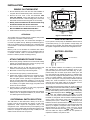
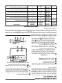
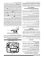
Blue 2” Single Stage Thermostat Installation and Operating Instructions Save these instructions for future use! FAILURE TO READ AND FOLLOW ALL INSTRUCTIONS CAREFULLY BEFORE INSTALLING OR OPERATING THIS CONTROL COULD CAUSE PERSONAL INJURY AND/OR PROPERTY DAMAGE. Model Programming Choices 1F86-0244 Non-Programmable APPLICATIONS 1F86-0244 Thermostat For use with the following Class II systems: • Single Stage systems • Single-stage heat pump systems with no Aux heat DO NOT USE WITH: • Systems exceeding 30 VAC and 1.5 amps • 3-wire zoned hydronic heating systems SPECIFICATIONS Electrical Rating: Battery Power.................................................. Input-Hardwire................................................. Terminal Load......................................................... Setpoint Range....................................................... Differential (Single Stage)....................................... Differential (Heat Pump)......................................... Operating Ambient.................................................. Operating Humidity................................................. Shipping Temperature Range................................. Dimensions Thermostat.......................................... mV to 30 VAC, 50/60 Hz or DC 20 to 30 VAC 1.0 A per terminal, 1.5A maximum all terminals combined 45° to 90°F (7° to 32°C) Heat 0.6°F; Cool 1.2°F (adjustable) Heat 1.2°F; Cool 1.2°F (adjustable) 32° to +105°F (0° to +41°C) 90% non-condensing max. -40° to +150°F (-40° to +65°C) 3-3/4” H x 4-3/4” W x 1-1/2” D PRECAUTIONS This thermostat is intended for use with a low voltage NEC Class II system. Do not use this thermostat with a line voltage system. If in doubt about whether your wiring is millivolt, line, or low voltage, have it inspected by a qualified heating and air conditioning contractor or electrician. Do not exceed the specification ratings. All wiring must conform to local and national electrical codes and ordinances. This control is a precision instrument, and should be handled carefully. Rough handling or distorting components could cause the control to malfunction. ! CAUTION ! WARNING Do not use on circuits exceeding specified voltage. Higher voltage will damage control and could cause shock or fire hazard. Do not short out terminals on gas valve or primary control to test. Short or incorrect wiring will damage thermostat and could cause personal injury and/or property damage. Thermostat installation and all components of the system shall conform to Class II (current limited) circuits per the NEC code. Failure to do so could cause a fire hazard. To prevent electrical shock and/or equipment damage, disconnect electric power to system at main fuse or circuit breaker box until installation is complete. www.white-rodgers.com PART NO. 37-7010B Replaces 37-7010A 0921 INSTALLATION Battery Door REMOVE OLD THERMOSTAT 1. Shut off electricity at the main fuse box until installation is complete. Ensure that electrical power is disconnected. 2. Remove the front cover of the old thermostat. With wires still attached, remove wall plate from the wall. If the old thermostat has a wall mounting plate, remove the thermostat and the wall mounting plate as an assembly. Mounting Hole Mounting Hole 3. Identify each wire attached to the old thermostat using the labels enclosed with the new thermostat. 4. Disconnect the wires from old thermostat one at a time. DO NOT LET WIRES FALL BACK INTO THE WALL. O/B Switch 5. Install new thermostat using the following procedures. Gas/Elec Switch ATTENTION! Opening for wires Figure 1. Thermostat Base This product does not contain mercury. However, this product may replace a unit which contains mercury. GAS / ELEC SWITCH Do not open mercury cells. If a cell becomes damaged, do not touch any spilled mercury. Wearing nonabsorbent gloves, take up the spilled mercury and place into a container which can be sealed. If a cell becomes damaged, the unit should be discarded. If your system is a heat pump, the GAS/ELEC Switch must be set to ELEC (see Fig. 1) If your system is a single stage, the switch must be set to GAS. The switch setting must agree with the system configuration selected in the configuration menu. Mercury must not be discarded in household trash. When the unit this product is replacing is to be discarded, place in a suitable container. Refer to www.white-rodgers.com for location to send the product containing mercury. BATTERY LOCATION “AA” Alkaline Batteries ATTACH THERMOSTAT BASE TO WALL 1. Remove the packing material from the thermostat. Gently pull the cover straight off the base. Forcing or prying on the thermostat will cause damage to the unit. 2. Place base over hole in wall and mark mounting hole locations on wall using base as a template (see Fig.1). Two “AA” alkaline batteries are installed in your thermostat with a battery tag to prevent power drainage. Prior to use, open the battery door and remove the battery tag. To open, pull the battery door as shown by the arrow and lift open. The two “AA” batteries will operate all functions or maintain time and continuously display the temperature during a loss of AC power. To replace batteries, pull the battery door shown by the arrow and lift open. Using the polarity indicated inside the battery door, insert the batteries. To close the battery door, swing the door down while pulling in the direction of arrow. Once fully down, snap the door back into position. 3. Move base out of the way. Drill mounting holes. 4. Push wires through opening in thermostat base. 5. Fasten base loosely to wall using two mounting screws. Place a level against bottom of base, adjust until level, and then tighten screws. (Leveling is for appearance only and will not affect thermostat operation.) If you are using existing mounting holes, or if holes drilled are too large and do not allow you to tighten base snugly, use plastic screw anchors to secure subbase. Thermostat can be powered by system AC power or Battery. If is displayed, the thermostat is battery powered. If is not displayed, thermostat is system powered with optional battery back-up. When battery power remaining is approximately half, the will be displayed. When “Change ” is displayed, install fresh “AA” alkaline batteries immediately. For best results, use new premium brand alkaline batteries such as Duracell® or Energizer®. We recommend replacing batteries every 2 years. If the home is going to be unoccupied for an extended period (over 3 months) and is displayed, the batteries should be replaced before leaving. When less than two months of battery life remain, the setpoint temperature will offset by 10 degrees (10 degrees cooler in Heat mode / 10 degrees warmer in Cool mode). If offset occurs, the normal setpoint can be manually reset with or . Another offset will occur within two days if batteries are not replaced. To replace the batteries, set system to OFF. 6. Connect wires to terminals on base using appropriate wiring schematic (see figs. 2 through 4). 7. Push excess wire into wall and plug hole with a fire-resistant material (such as fiberglass insulation) to prevent drafts from affecting thermostat operation. O/B TERMINAL SWITCH SELECTION The O/B switch on this thermostat is factory set to the “O” position. This will accommodate the majority of heat pump applications, which require the changeover relay to be energized in COOL. If the thermostat you are replacing or the heat pump being installed with this thermostat requires a “B” terminal, to energize the changeover relay in HEAT, the O/B switch must be moved to the “B” position. WIRING DIAGRAMS Optional Jumper for Single Stage Heat Pump THERMOSTAT O/B Y Changeover Relay* G W Fan Relay Compressor Contactor R C SYSTEM Optional Heat Relay Hot 24 VAC 120 VAC Neutral * Changeover Relay is energized in COOL when O/B switch is in the “O” position Changeover Relay is energized in HEAT when O/B switch is in the “B” position TRANSFORMER (Class II Current Limited) Figure 2. Typical wiring diagram for single transformer single stage systems NOTE If safety circuits are in only one of the systems, remove the transformer of the system with NO safety circuits. Optional Jumper for Single Stage Heat Pump THERMOSTAT O/B CUT AND TAPE OFF! Y Changeover Relay* HOT 24 VAC 120 VAC G Fan Relay Compressor Contactor NEUTRAL W C R Optional Limit or Safety Switches SYSTEM Heat Relay Hot 24 VAC 120 VAC Neutral * Changeover Relay is energized in COOL when O/B switch is in the “O” position Changeover Relay is energized in HEAT when O/B switch is in the “B” position TWO COMMONS MUST BE JUMPERED TOGETHER! TRANSFORMER (Class II Current Limited) Figure 3. Typical wiring diagram for two transformer single stage systems with NO safety circuits NOTE Polarity must be observed. If the HOT side of the second transformer is jumpered to the COMMON side of the first transformer a short will be made. Damage to equipment will occur when power is restored. Optional Jumper for Single Stage Heat Pump THERMOSTAT O/B Y Changeover Relay* Compressor Contactor G W Fan Relay C R SYSTEM Limit or Safety Switches Optional 24 VAC 24 VAC ACCESSORY RELAY N.O. CONTACT Heat Relay COMMON Limit or Safety Switches TWO COMMONS MUST BE JUMPERED TOGETHER! COMMON * Changeover Relay is energized in COOL when O/B switch is in the “O” position Changeover Relay is energized in HEAT when O/B switch is in the “B” position 24 VAC 120 VAC Limit or Safety HOT Switches NEUTRAL Auxiliary NOTE Heating Transformer The accessory relay scheme (Class II Current Limited) is required when safety circuits exist in both systems. 120 VAC Heat Pump Transformer (Class II Current Limited) Limit or Safety Switches HOT NEUTRAL Figure 4. Typical wiring diagram for two transformer single stage systems with safety circuits in BOTH systems THERMOSTAT QUICK REFERENCE Before you begin using your thermostat, you should be familiar with its features and with the display and the location and operation of the thermostat buttons and switches (see fig. 5). Your thermostat consists of two parts: the thermostat cover and the base. To remove the cover, pull it straight out from the base. To replace the cover, line up the cover with the base and press until the cover snaps onto the base. 8 Displays current temperature. 9 “Service” indicates a diagnostic fault in the heating/cooling system. It does not indicate a fault in the thermostat. 10 “Change Filter” is displayed when the system has run for the programmed filter time period as a reminder to change or clean your air filter. 11 “ ” indicates power level of batteries. “Change indicates batteries should be replaced. The Thermostat Buttons and Switches 1 Raises temperature setting. ” Figure 5. Thermostat display, buttons, and switches 2 Lowers temperature setting. 3 SYSTEM switch (COOL, OFF, HEAT). 4 FAN switch (ON, AUTO). 1 The Display 2 5 Indicates days of the week. Indicates setpoint temperature. This is blank when system switch is in the OFF position. Setpoint temperature is displayed (flashing) if the thermostat is in lockout mode to prevent the compressor from cycling too quickly. 6 “Save” indicates the Cool Savings feature is enabled in the configuration menu. “Save” (flashing) indicates Cool Savings feature is active. 7 Flame icon ( ) is displayed when the SYSTEM switch is in the HEAT position. Flame icon ( ) is displayed flashing when thermostat is calling for heat. Snowflake icon ( ) is displayed (non-flashing) when the SYSTEM switch is in the COOL position. Snowflake icon ( ) and is displayed (flashing) if the thermostat is calling for cool. SYSTEM 3 4 5 11 6 10 9 8 7 INSTALLER/CONFIGURATION MENU The configuration menu allows you to set certain thermostat operating characteristics to your system or personal requirements. To enter the menu: Set your thermostat to OFF and press the and buttons simultaneously. The display will show the first item in the configuration menu. Press and to change to the next menu item. To exit the menu, set the system switch to Cool or Heat. If no keys are pressed within fifteen minutes, the thermostat will revert to normal operation. Configuration Menu Menu Reference Number Press Key Displayed (Factory Default) 1 and SS HP 2 and CS (OFF) On and 3 and 4 and 5 and Press or to select from listed options Comments Select Single Stage (SS) or Heat Pump (HP, 1 compressor) Select Cool Savings Feature On or OFF CS (3) 1, 2, 3, 4, 5, 6 CR Cool (FA) SL CR Heat (ME) FA, SL CL (OFF) On If CS selected On, selects Cool Savings value Select Adjustable Anticipation, cycle rate, Heat Single Stage Select Adjustable Anticipation, cycle rate, Cool Single Stage Select Compressor lockout OFF or On Menu Reference Number Press Key Displayed (Factory Default) 6 and 7 L (On) and 8 and 9 and Change Filter (OFF) On and Change Filter (200 h) 25 to 1975 10 Press or to select from listed options OFF Temp (0 HI) o o C 7) Select Temperature Display Adjustment 4 LO to 4 HI Allows you to adjust the room temperature display up to 4° higher or lower. Your thermostat was accurately calibrated at the factory but you have the option to change the display temperature to match your previous thermostat. The current or adjusted room temperature will be displayed on the display. 8) Select F° or C° Readout - Changes the display readout to Celsius or Fahrenheit as required. 9) Select Filter Replacement Reminder and Set Run Time Select the “Change Filter” reminder On or OFF. If selected On, press and to select the time period from 25 to 1975 hours in 25 hour increments. In a typical application, 200 hours (default) of run time is approximately 30 days. After the selected time of blower operation, the thermostat will display “Change Filter” as a reminder to change or clean your air filter. When “Change Filter” is displayed, press the and button to clear the display and restart the time to the next filter change. A selection of OFF will cancel this feature. The cycle rate differentials for different settings are: MODE Fast (FA) (ME) (SL) 1.2°F - 1.7°F SS Heat SS Cool If Change Filter selected On, selects time interval for Change Filter Indicator. (in 25 hour increments) 6) Select Backlight Display - The display backlight improves display contrast in low lighting conditions. When the “C” terminal is connected, selecting backlight CdL On will keep the light on continuously. Select backlight OFF will turn the light on momentarily when any key is pressed. When the “C” terminal is not connected, regardless of the backlight selection, the light will be on momentarily when any key is pressed. 3 & 4) Select Cycle Rate Selection - The factory default setting for Single Stage Heat is Medium Cycle (ME). For Single Stage Cool the default setting is fast (FA). To change cycle rate, press the and buttons. Select oF / oC Display (temperature units in Fahrenheit or Celsius) Returns to normal operation and 2) Select CS (Cool Savings™) - With Cool Savings™ enabled, the thermostat will make small adjustments to the Setpoint temperature during periods of high demand to reduce cooling system running time and save energy. When the cooling system has been running for more than 20 minutes, humidity in the home will be lower and a higher setpoint temperature will feel comfortable. After 20 minutes of run time, the thermostat will start increasing the setpoint temperature in steps of less than one degree as the system continues to run. These adjustments will eventually cause the system to satisfy the thermostat and turn the system off to reduce the energy consumption. When the Cool Savings feature is active and making adjustments, the display will show “Save”. The amount of the adjustments to the setpoint temperature is dependent on the Cool Savings value that is set, 1 being the least adjustment and 6 being the most adjustment. With this feature set to OFF, no change will occur when the cooling system is continuously running during the periods of high demand. Periods of high demand will normally occur during the late afternoon and early evening on the hottest days of the summer. Select temperature display adjustment higher or lower Select filter replacement indicator OFF or On 1) System Configuration - Selects SS (Single Stage) or HP (Heat Pump) operating mode. Default configuration is SS. For Heat Pump operation choose HP. Select Display Light On or OFF 4 LO to 4 HI F Comments 0.6°F Medium Slow 0.8°F 1.2°F 5) Select Compressor Lockout CL OFF or ON - Selecting CL On will cause the thermostat to wait 5 minutes between cooling cycles. This is intended to help protect the compressor from short cycling. Some newer compressors already have a time delay built in and do not require this feature. Your compressor manufacturer can tell you if the lockout feature is already present in their system. When the thermostat compressor time delay occurs, it will flash the setpoint for up to five minutes. OPERATION CHECK THERMOSTAT OPERATION Cooling System If at any time during testing your system does not operate properly, contact a qualified service person. ! CAUTION Turn on power to the system. To prevent compressor and/or property damage, if the outdoor temperature is below 50oF, DO NOT operate the cooling system. Fan Operation If your system does not have a G terminal connection, skip to Heating System. 1. Move SYSTEM switch to COOL position. 2. Press to adjust thermostat setting below room temperature. The blower should come on immediately on high speed, followed by cold air circulation. However, if the setpoint temperature is flashing, the compressor lockout feature is operating (see Configuration menu, item 5). 1. Move fan switch to ON position. The blower should begin to operate. 2. Move fan switch to AUTO position. The blower should stop immediately. 3. Press to adjust temperature setting above room temperature. The cooling system should stop operating. Heating System 1. Move SYSTEM switch to HEAT position. If the auxiliary heating system has a standing pilot, be sure to light it. ! CAUTION 2. Press to adjust thermostat setting to 1° above room temperature. The heating system should begin to operate. Do not allow the compressor to run unless the compressor oil heaters have been operational for 6 hours and the system has not been operational for at least 5 minutes. 3. Press to adjust temperature setting below room temperature. The heating system should stop operating. TROUBLESHOOTING Reset Operation If a voltage spike or static discharge blanks out the display or causes erratic thermostat operation, you may need to reset the thermostat. To reset, the System Switch must be in Cool or Heat. Simultaneously press and buttons for approximately 10 seconds until the display goes blank. If the thermostat has power, has been reset and still does not function correctly contact your heating/cooling service person or place of purchase. Symptom Possible Cause Corrective Action No Heat/No Cool/No Fan common problems) 1. Blown fuse or tripped circuit breaker. 2. Furnace power switch to OFF. 3. Furnace blower compartment door or panel loose or not properly installed. Replace fuse or reset breaker. Turn switch to ON. Replace door panel in proper position to engage safety interlock or door switch. No Heat 1. System Switch not set to Heat. Set System Switch to Heat and raise setpoint above room temperature. Verify thermostat and system wires are securely attached. Diagnostic: Set System Switch to Heat and raise the setpoint above room temperature. Within a five minutes the thermostat should make a soft slick sound. This sound usually indicates the thermostat is operating properly. If the thermostat does not click, try the reset operation listed above. If the thermostat does not click after being reset contact your heating and cooling service person or place of purchase for a replacement. If the thermostat clicks, contact the furnace manufacturer or a service person to verify the heating system is operating correctly. 2. Loos connection to thermostat or system 3. Heating System requires service or thermostat requires replacement. No Cool 1. System Switch not set to Cool. 2. Loose connection to thermostat or system. 3. Cooling System requires service or thermostat requires replacement Set System Switch to Cool and lower setpoint below room temperature. Verify thermostat and system wires are securely attached. Same procedures as diagnostic for No Heat condition except set the thermostat to Cool and lower the setpoint below the room temperature. There may be up to a five minute delay before the thermostat clicks in Cooling if the compressor lock-out option is selected in the configuration menu (Item 5). Heat, Cool or Fan Runs Constantly 1. Possible short in wiring. 2. Possible short in thermostat. 3. Possible short in Heat/Cool/Fan system. 4. Fan Switch set to Fan On. Check each wire connection to verify they are not shorted or touching together. No bare wire should stick out from under terminal screws. Try resetting the thermostat as described below. If the condition persists, the manufacturer of your system or service person can instruct you on how to test the Heat/Cool/ system for correct operation. If the system operates correctly, replace the thermostat. Furnace Cycles Too Fast or Too Slow Cooling Cycles Too Fast or Too Slow (narrow or wide temperature swing) 1. The location of the thermostat and/or the size of the Heating or Cooling System may be influencing the cycle rate. Item 3 (CR Heat) or 4 (CR Cool) in the Configuration Menu is the adjustment that controls the cycle rate. If an acceptable cycle rate is not achieved using the FA (Fast) or SL (Slow) adjustment contact a local service person for additional suggestions. Thermostat Setting and Thermometer Disagree 1. Thermostat thermometer setting requires adjustment. The thermometer can be adjusted +/- degrees as listed in item 7 of the Configuration Menu. No other adjustment is possible. Blank Display and/or Keypad Not Responding 1. Voltage Spike or Static Discharge. If a voltage spike or static discharge occurs use the Reset Operation listed above. Homeowner Help Line: 1-800-284-2925 White-Rodgers is a division of Emerson Electric Co. The Emerson logo is a trademark and service mark of Emerson Electric Co. www.white-rodgers.com Línea de ayuda para el usuario: 1-800-284-2925 White-Rodgers es una división de Emerson Electric Co. El logotipo de Emerson es una marca comercial y una marca de servicio de Emerson Electric Co. www.white-rodgers.com SOLUCIÓN DE PROBLEMAS Operación de reajuste Si un pico de voltaje o una descarga estática pone en blanco la pantalla o hace que el termostato funcione de manera errática, es posible que necesite reajustar el termostato. Para reajustar, el interruptor del sistema tiene que estar en Cool o Heat. Presione los botones y al mismo tiempo durante aproximadamente 10 segundos hasta que la pantalla se ponga en blanco. Si el termostato tiene alimentación y se ha reajustado pero aún no funciona correctamente, póngase en contacto con su servicio técnico de calefacción/enfriamiento o con el lugar donde realizó la compra. Verifique todas las conexiones de los cables para asegurarse de que no estén en cortocircuito o tocándose entre sí. No debe sobresalir ningún cable pelado por debajo de los tornillos terminales. Intente reajustar el termostato. Si la condición persiste, el fabricante de su sistema o el personal técnico podrá indicarle cómo probar si el sistema de calor/ frío está funcionando correctamente. Si el sistema funciona correctamente, cambie el termostato. 1.Posible cortocircuito en los cables. 2.Posible cortocircuito en el termostato. 3.Posible cortocircuito en el sistema de calor/frío/ventilador. 4.El interruptor Fan está en Fan ON. El modo de calor, frío o ventilador funciona de manera constante Ajuste el interruptor System en Cool y baje la temperatura de referencia por debajo de la temperatura ambiente. Verifique que los cables del termostato y del sistema estén bien conectados. Siga el mismo procedimiento de diagnóstico que cuando el sistema no calienta pero coloque el termostato en Cool y coloque la temperatura de referencia por debajo de la temperatura ambiente. El termostato puede tardar hasta cinco minutos en pasar al modo de enfriamiento si se ha seleccionado la opción de bloqueo del compresor en el menú de configuración (opción 5). 1.El interruptor System no está ajustado en Cool. 2.La conexión al termostato o al sistema está suelta. 3.El sistema de enfriamiento requiere servicio técnico o debe cambiarse el termostato. El sistema no enfría Ajuste el interruptor System en Heat y suba la temperatura de referencia por encima de la temperatura ambiente. Verifique que los cables del termostato y del sistema estén bien conectados. Diagnóstico: Ajuste el interruptor System en Heat y suba la temperatura de referencia por encima de la temperatura ambiente. En menos de cinco minutos, debería oírse un chasquido suave del termostato. Por lo general, este sonido indica que el termostato está funcionando correctamente. Si no se oye un chasquido, intente la operación de reajuste arriba indicada. Si el termostato no hace un chasquido después de reajustarlo, póngase en contacto con su personal de servicio técnico de calefacción y enfriamiento o con el lugar de compra para obtener un reemplazo. Si el termostato hace un chasquido, póngase en contacto con el fabricante del calefactor o con personal técnico especializado para verificar que la calefacción esté funcionando correctamente. 1.El interruptor System no está ajustado en Heat. 2.La conexión al termostato o al sistema está suelta. 3.El sistema de calefacción requiere servicio técnico o debe cambiarse el termostato. El sistema no calienta 1.Se quemó el fusible o se disparó el disyuntor. 2.El interruptor de alimentación del calefactor está en OFF. 3.La puerta o el panel del compartimiento del soplador del calefactor están sueltos o no están debidamente instalados. El sistema no calienta/ El sistema no enfría/ No funciona el ventilador (problemas comunes) Causa posible Síntoma Los ciclos del calefactor/ 1.La ubicación del termostato y/o el aire acondicionado tamaño del sistema de calefacción son demasiado cortos o enfriamiento pueden influir en la o demasiado largos duración de los ciclos. (oscilación reducida o amplia de la temperatura) Acción correctiva Cambie el fusible o vuelva a activar el disyuntor. Coloque el interruptor en ON. Vuelva a colocar el panel de la puerta en el lugar correcto para que se enganche con el interruptor de interbloqueo de seguridad o de la puerta. La opción 3 (CR Calor) o 4 (CR Frío) del menú de configuración es el ajuste que controla la velocidad del ciclo. Si no obtiene una duración de ciclo aceptable usando el ajuste FA (Rápido) o SL (Lento), póngase en contacto con personal técnico local para que le sugieran otras soluciones. 1.Pico de voltaje o descarga estática. La pantalla está en blanco y/o el teclado no responde 1.Es necesario ajustar el termómetro El termómetro puede ajustarse en +/- grados según se indica del termostato. en la opción 7 del menú de configuración. No es posible realizar ningún otro ajuste. El ajuste del termostato no coincide con el termómetro Si se produce un pico de voltaje o descarga estática, siga las indicaciones de la sección Operación de reajuste anterior. FUNCIONAMIENTO VERIFIQUE EL FUNCIONAMIENTO DEL TERMOSTATO Si en algún momento durante la prueba su sistema no funciona correctamente, póngase en contacto con un servicio técnico calificado. Encienda la alimentación del sistema. Funcionamiento del ventilador Si su sistema no tiene una conexión terminal G, pase directa mente a la sección Sistema de calefacción. 1. Mueva el interruptor FAN a la posición ON. El soplador debería comenzar a funcionar. 2. Mueva el interruptor FAN a la posición AUTO. El soplador debería detenerse inmediatamente. Sistema de calefacción 1. Mueva el interruptor SYSTEM a la posición HEAT. Si el sistema de calefacción auxiliar tiene un piloto, asegúrese de encenderlo. para ajustar la configuración del termostato 2. Presione 1° por encima de la temperatura ambiente. El sistema de calefacción debería comenzar a funcionar. para ajustar la configuración de la temperatura 3. Presione por debajo de la temperatura ambiente. El sistema de calefacción debería dejar de funcionar. Sistema de enfriamiento ¡PRECAUCIÓN! Para evitar daños al compresor y/o daños materiales, si la temperatura externa está por debajo de los 50°F, NO utilice el sistema de enfriamiento. 1. Mueva el interruptor SYSTEM a la posición COOL. 2. Presione para ajustar la configuración del termostato por debajo de la temperatura ambiente. El soplador debería encenderse inmediatamente a alta velocidad, seguido de circulación de aire frío. No obstante, si la temperatura de referencia aparece intermitente, significa que la función de bloqueo del compresor está funcionando (vea la sección Menú de configuración, opción 5). 3. Presione para ajustar la configuración de la temperatura por encima de la temperatura ambiente. El sistema de enfriamiento debería dejar de funcionar. ¡PRECAUCIÓN! No deje que el compresor funcione a menos que los calentadores de aceite del compresor hayan estado en funcionamiento durante 6 horas y que el sistema no haya estado en funcionamiento durante al menos 5 minutos. 25 a 1975 Change Filter (200 h) y ON Change Filter (OFF) y 9 F y 8 4 LO (4 más abajo) a 4 HI (4 más arriba) Temp (0 HI) y 7 OFF L (On) y 6 Presione el botón Número de referencia del menú 10 Pantalla (ajuste de fábrica) o Presione o para seleccionar las siguientes opciones o C Las velocidades de los ciclos son las indicadas a continuación según la opción elegida: MODO Rápido Medio (FA) SS Heat 0.6 °F SS Cool Observaciones Selecciona la luz de fondo de la pantalla en On u OFF Selecciona el ajuste de la temperatura visualizada más arriba o más abajo Selecciona pantalla en °F/°C (unidades de temperatura Fahrenheit o Celsius) Selecciona el tiempo de ejecución de reemplazo de filtro en OFF u ON Si Change Filter está en On, selecciona el intervalo de tiempo del indicador de cambio de filtro (en incrementos de 25 horas) Vuelve al funcionamiento normal y 1) Configuración del sistema - Selecciona el modo de funcionamiento SS (una sola etapa) o HP (bomba de calor). La configuración predeterminada es SS. Para el funcionamiento como bomba de calor seleccione HP. 2) Seleccione CS (Cool Savings™) - Con Cool Savings™ activado, el termostato realizará pequeños ajustes a la temperatura de referencia durante los períodos de alta demanda para reducir el tiempo de funcionamiento del sistema de enfriamiento y ahorrar energía. Cuando el sistema de enfriamiento lleva funcionando más de 20 minutos, la humedad presente en la casa es inferior y una temperatura de referencia más alta será confortable. Después de 20 minutos de funcionamiento, el termostato comenzará a aumentar la temperatura de referencia en incrementos de menos de un grado mientras el sistema continúa funcionando. Estos ajustes harán que el sistema “satisfaga” finalmente al termostato y que éste apague el sistema, lo cual permitirá reducir el consumo de energía. Cuando la función Cool Savings está activada y realizando ajustes, la pantalla mostrará el mensaje “Save”. La cantidad de ajustes en la temperatura de referencia depende del valor de Cool Savings definido: 1 es el ajuste mínimo y 6 el máximo. Cuando esta función está en OFF, no se realizarán cambios cuando el sistema está funcionando de forma continua con el sistema de enfriamiento durante el período de alta demanda. Normalmente, los períodos de alta demanda se producen en las últimas horas de la tarde y a comienzos de la noche en los días más calurosos de verano. 3 y 4) Selección de la velocidad del ciclo – El ajuste predeterminado de fábrica para el modo Heat de una sola etapa es el ciclo medio (ME). Para el modo Cool de una sola etapa el ajuste predeterminado es el ciclo rápido (FA). Para cambiar la velocidad del ciclo, presione el botón y el botón . 1.2 °F (ME) 0.8 °F - Lento (SL) 1.2 °F si su modelo incluye la función de bloqueo. Cuando se activa la demora de tiempo del compresor del termostato, la pantalla mostrará la temperatura de referencia de forma intermitente durante un máximo de cinco minutos. 6) Seleccione luz de fondo de la pantalla - La luz de fondo mejora el contraste de la pantalla en condiciones de poca luz. Cuando la terminal “C” está conectada, la selección de CdL On mantendrá la luz de fondo encendida de forma continua. Al seleccionar OFF, la luz se mantendrá momentáneamente encendida después de presionar cualquier botón. Cuando la terminal “C” no está conectada, independientemente de la selección de la luz de fondo, la luz se mantendrá momentáneamente encendida después de presionar cualquier botón. 7) Selección del ajuste de la pantalla de temperatura de 4 LO (4 más abajo) a 4 HI (4 más arriba) - Le permite ajustar la visualización de la temperatura ambiente 4° más arriba o más abajo. El termostato viene calibrado con precisión de fábrica pero usted tiene la opción de cambiar el valor de temperatura que aparece en la pantalla para que coincida con el de su termostato anterior. La pantalla mostrará la temperatura ambiente actual o ajustada. 8) Seleccione F° o C° - Cambia la unidad en que aparece la temperatura en la pantalla a grados centígrados o Fahrenheit según su preferencia. 9) Selección de aviso de cambio de filtro y ajuste de tiempo de funcionamiento – Seleccione el recordatorio “Change Filter” en On (activado) u OFF (desactivado). Si selecciona On, presione y para seleccionar la cantidad de tiempo desde 25 hasta 1975 horas en incrementos de 25 horas. En una aplicación típica, 200 horas de tiempo de funcionamiento (valor predeterminado) equivalen a aproximadamente 30 días. Una vez seleccionado el tiempo de funcionamiento del soplador, el termostato mostrará “Change Filter” como recordatorio para cambiar o limpiar su filtro de aire. Cuando aparezca “Change Filter” presione el botón y para borrar la pantalla y reiniciar la hora para el siguiente cambio de filtro. Si elige OFF, se cancelará esta función. 1.7 °F 5) Selección de bloqueo del compresor (CL) en OFF u ON – Si se selecciona CL On, el termostato esperará 5 minutos entre ciclos de enfriamiento para evitar que el compresor realice ciclos de encendido y apagado cortos. Algunos de los compresores más nuevos ya tienen incorporada una demora de tiempo y no requieren que esta función esté activada en el termostato. Consulte al fabricante de su compresor para saber GUÍA DE REFERENCIA RÁPIDA DEL TERMOSTATO Antes de que comience a programar su termostato, debe familiarizarse con sus funciones y con la pantalla y la ubicación y funcionamiento de los diferentes botones interruptores (vea figura 5). Su termostato consta de dos partes: la cubierta del termostato y la base. Para retirar la cubierta, tire suavemente de ella para separarla de la base. Para volver a colocarla, alinee la cubierta con la base y presione suavemente hasta que se enganche en la base. Los botones e interruptores del termostato 1 Sube el ajuste de temperatura. 2 Baja el ajuste de temperatura. 8 Muestra la temperatura actual. 9 “Service” (servicio) indica una falla en el sistema de calefacción/enfriamiento. No indica una falla del termostato. 10 “Change Filter” (cambiar filtro) aparece cuando el sistema se ha utilizado por la cantidad de tiempo seleccionada en el filtro para recordarle que debe cambiar o limpiar el filtro de aire. 11 “ ” muestra el nivel de alimentación de las pilas. “Change ” (cambiar) indica que las pilas deben cambiarse. Figura 5. Pantalla, botones e interruptores del termostato 3 Interruptor SYSTEM (COOL, OFF, HEAT). 4 Interruptor FAN (ventilador) (ON, AUTO). 1 2 La pantalla 5 Muestra los días de la semana. Muestra la temperatura de referencia. Esta aparece en blanco cuando el interruptor está en la posición OFF. La temperatura de referencia aparece de forma intermitente si el termostato está en el modo de bloqueo para evitar que el compresor realice ciclos de encendido y apagado demasiado rápidos. 6 “Save” (ahorro) indica que la función Cool Savings está activada en el menú instalador. “Save” intermitente indica que la función Cool Savings está activa. SYSTEM 3 7 El icono de la llama ( ) aparece cuando el interruptor SYSTEM está en la posición HEAT. El icono de la llama ( ) aparece intermitente cuando el termostato realiza una llamada de calor. El icono del copo de nieve ( ) aparece (fijo) cuando el interruptor SYSTEM está en la posición COOL. El copo de nieve aparece ( ) (intermitente) cuando el termostato realiza una llamada de frío. 4 5 11 6 10 9 8 7 MENÚ INSTALADOR/DE CONFIGURACIÓN El menú de configuración le permite ajustar ciertas características operativas del termostato según el sistema o sus necesidades particulares. Para ingresar en el menú: Coloque el termostato en OFF y presione los botones y al mismo tiempo. La pantalla mostrará la primera opción del menú de configuración. Presione y para pasar a la siguiente opción del menú. Para salir del menú, coloque el interruptor del sistema en Cool o Heat. Si pasan quince minutos sin presionar ningún botón, el termostato volverá al modo de funcionamiento normal. Menú de configuración On CL (OFF) y 5 LENTO CR Cool (FA) y 4 RÁPIDO, LENTO CR Heat (ME) y 3 1, 2, 3, 4, 5, 6 CS (3) y On CS (OFF) y 2 SS y 1 Presione el botón Número de referencia del menú Pantalla (ajuste de fábrica) Presione o para seleccionar las siguientes opciones HP Observaciones Selecciona una sola etapa (SS) o bomba de calor (HP, 1 compresor) Selecciona la función Cool Savings On u OFF Si CS está en On, selecciona el valor de Cool Savings Selecciona anticipación ajustable, velocidad de ciclo, calor de una sola etapa Selecciona anticipación ajustable, velocidad de ciclo, frío de una sola etapa Selecciona el bloqueo del compresor OFF u On CONEXIONES ELÉCTRICAS Puente opcional para bomba de calor de una sola etapa SISTEMA O/B Relé de conmutación* Y G Contactor del compresor Relé del ventilador W Relé de calor C R TERMOSTATO Opcional Vivo 24 VCA * El relé de conmutación está energizado en COOL cuando el interruptor O/B está en la posición “O” El relé de conmutación está energizado en HEAT cuando el interruptor O/B está en la posición “B” 120 VCA Neutro TRANSFORMADOR (corriente limitada Clase II) Figura 2. Diagrama de conexiones típico para sistemas de una sola etapa de un solo transformador NOTA Si los circuitos de seguridad sólo se encuentran en uno de los sistemas, retire el transformador del sistema SIN circuitos de seguridad. ¡CORTE Y AÍSLE CON CINTA! VIVO Puente opcional para bomba de calor de una sola etapa SISTEMA Relé del ventilador Relé de conmutación* G O/B 24 VCA 120 VCA Y W Contactor del compresor NEUTRO C R TERMOSTATO Interruptores limitadores o de seguridad Opcional Relé de calor Vivo 24 VCA ¡LOS DOS NEUTROS DEBEN PUENTEARSE! * El relé de conmutación está energizado en COOL cuando el interruptor O/B está en la posición “O” El relé de conmutación está energizado en HEAT cuando el interruptor O/B está en la posición “B” 120 VCA Neutro TRANSFORMADOR (corriente limitada Clase II) Figura 3. Diagrama de conexiones típico para sistemas de una sola etapa de dos transformadores SIN circuitos de seguridad NOTA Debe prestarse atención a la polaridad. Si el lado VIVO del segundo transformador se une con el lado NEUTRO del primer transformador, se producirá un cortocircuito. Se producirán daños en el equipo cuando se restablezca el suministro eléctrico. Puente opcional para bomba de calor de una sola etapa SISTEMA Relé del ventilador Relé de conmutación* G O/B Y W C R TERMOSTATO Interruptores limitadores o de seguridad 24 VCA Opcional Contactor del compresor CONTACTO N/O DE RELÉ ACCESORIO DE 24 VCA Relé de calor 120 VCA 24 VCA Interruptores limitadores o VIVO de seguridad NEUTRO Transformador de calefacción auxiliar (corriente limitada Clase II) NEUTRO Interruptores limitadores o de seguridad ¡LOS DOS NEUTROS DEBEN PUENTEARSE! NEUTRO * El relé de conmutación está energizado en COOL cuando el interruptor O/B está en la posición “O” El relé de conmutación está energizado en HEAT cuando el interruptor O/B está en la posición “B” NOTA Se requiere el esquema de relé accesorio cuando existen circuitos de seguridad en ambos sistemas. Interruptores limitadores o de seguridad VIVO 120 VCA NEUTRO Transformador de bomba de calor (corriente limitada Clase II) Figura 4. Diagrama de conexiones típico para sistemas de una sola etapa de dos transformadores con circuitos de seguridad en AMBOS sistemas INSTALACIÓN RETIRE EL TERMOSTATO VIEJO Puerta del compartimiento de pilas 1. Apague la electricidad en la caja de fusibles principal hasta que haya finalizado la instalación. Asegúrese de que la alimentación eléctrica esté desconectada. 2. Retire la cubierta delantera del termostato viejo. Con los cables aún conectados, retire la placa de la pared. Si el termostato viejo tiene una placa de montaje sobre pared, retire el termostato y la placa juntos. Orificios de montaje Orificios de montaje 3. Identifique cada uno de los cables conectados al termostato viejo usando las etiquetas incluidas con el nuevo termostato. 4. Desconecte los cables del termostato viejo de a uno a la vez. NO DEJE QUE LOS CABLES VUELVAN A INTRODUCIRSE EN LA PARED. Interruptor O/B 5. Instale el termostato nuevo siguiendo el procedimiento indicado a continuación. Interruptor de gas/eléctrico Abertura para cables Figura 1 – Base del termostato ¡ATENCIÓN! Este producto no contiene mercurio. No obstante, puede reemplazar un producto que sí contiene mercurio. No abra las celdas de mercurio. En el caso de que una celda se dañe, no toque el mercurio derramado. Usando un par de guantes no absorbentes, recoja el mercurio derramado y viértalo en un recipiente que pueda sellarse. Si se daña una celda, debe desecharse la unidad. INTERRUPTOR GAS/ELEC Si su sistema es una bomba de calor, el interruptor GAS/ELEC debe colocarse en ELEC (vea la figura 1). Si su sistema es de una sola etapa, el interruptor debe colocarse en GAS. El ajuste del interruptor debe coincidir con la configuración del sistema seleccionada en el menú de configuración. El mercurio no debe desecharse con los residuos domésticos. Para desechar la unidad que será reemplazada por este equipo, colóquela en un recipiente adecuado. Consulte en www.whiterodgers.com dónde enviar los productos que contienen mercurio. UBICACIÓN DE LAS PILAS Pilas alcalinas “AA” FIJE LA BASE DEL TERMOSTATO A LA PARED 1. Retire el material de embalaje del termostato. Tire suavemente de la cubierta para separarla de la base. Si fuerza o hace palanca sobre el termostato dañará la unidad. 2. Coloque la base sobre el orificio de la pared y marque las ubicaciones de los orificios de montaje usando la base como plantilla (vea figura 1). 3. Mueva la base a un lado. Perfore los orificios de montaje. 4. Empuje los cables a través de la abertura en la base del termostato. 5. Fije la base a la pared sin ajustarla demasiado, usando dos tornillos de montaje. Coloque un nivel contra la parte inferior de la base, ajústela hasta que quede bien nivelada y luego apriete los tornillos. (Esto es por razones estéticas solamente y no afectará el funcionamiento del termostato.) Si utiliza los orificios de montaje existentes, o si los orificios perforados son demasiado grandes y no le permiten ajustar bien la base, use anclajes plásticos para fijar la subbase. 6. Conecte los cables al bloque de terminales sobre la base consultando el esquema de conexiones correspondiente (vea las figuras 2 a 4). 7. Empuje el cable que sobresale hacia el interior de la pared y tape el orificio con un material ignífugo (como aislamiento de fibra de vidrio) para evitar que las corrientes de aire afecten el funcionamiento del termostato. INTERRUPTOR DE SELECCIÓN DE TERMINAL O/B El interruptor O/B de este termostato viene ajustado de fábrica en la posición “O”. Esta opción admite la mayoría de las aplicaciones de bomba de calor, que requieren que el relé de conmutación esté energizado en COOL. Si el termostato que está cambiando o la bomba de calor que está instalando con este termostato requiere una terminal “B”, para energizar el relé de conmutación en HEAT, el interruptor O/B debe colocarse en la posición “B”. El termostato incluye dos pilas alcalinas “AA” instaladas con una banda de unión para evitar que se descarguen. Antes de usar el termostato, abra la puerta del compartimiento de las pilas y retire la banda de unión. Para abrirla, tire de la puerta como muestra la flecha y levántela. Las dos pilas “AA” permitirán activar todas las funciones o mantener la hora y mostrar de forma permanente la temperatura durante una pérdida de alimentación CA. Para cambiar las pilas, tire de la puerta del compartimiento como muestra la flecha y levántela. Coloque las pilas según la polaridad indicada dentro de la puerta del compartimiento. Para cerrar la puerta del compartimiento de las pilas, gírela hacia abajo mientras tira en el sentido indicado por la flecha. Cuando esté totalmente abajo, enganche la puerta en su lugar. El termostato puede funcionar con la alimentación CA del sistema o con pilas. Si el símbolo aparece, significa que el termostato está funcionando con pilas. Si el símbolo no aparece significa que el termostato está funcionando con la alimentación del sistema y, además, cuenta con alimentación auxiliar opcional con pilas. Cuando la carga de las pilas se encuentra aproximadamente en la mitad, aparecerá el símbolo . Cuando aparezca el mensaje “Change ” (Cambiar), instale dos pilas alcalinas “AA” nuevas inmediatamente. Para obtener resultados óptimos, use pilas alcalinas nuevas de alguna marca líder como Duracell® o Energizer®. Recomendamos cambiar las pilas cada 2 años. Si la vivienda va a estar desocupada durante un tiempo prolongado (más de 3 meses) y aparece el símbolo , las pilas deben cambiarse antes de partir. Cuando a las pilas les quedan menos de dos meses de vida útil, la temperatura de referencia se compensará en 10 grados (10 grados menos en el modo Heat y 10 grados más en el modo Cool). Si se produce esta compensación, puede reajustarse la temperatura de referencia normal con los botones o . Si no se cambian las pilas, tendrá lugar otra compensación dentro de los dos días. Para cambiar las pilas, coloque el sistema en OFF. ¡Conserve estas instrucciones para consultarlas en cualquier momento! EL NO LEER Y SEGUIR CON CUIDADO TODAS LAS INSTRUCCIONES ANTES DE INSTALAR O UTILIZAR ESTE CONTROL PODRÍA CAUSAR LESIONES PERSONALES Y/O DAÑOS MATERIALES. Termostato de una sola etapa Blue 2” Instrucciones de instalación y operación Modelo 1F86-0244 Opciones de programación No-Programable APLICACIONES Termostato 1F86-0244 Para utilizar con los siguientes sistemas Clase II: • Sistemas de una sola etapa • Sistemas de bomba de calor de una sola etapa sin calor auxiliar NO UTILIZAR CON: • Sistemas que exceden los 30 VCA y 1.5 A • Sistemas de calefacción hidrónicos zonificados de 3 cables ESPECIFICACIONES Características eléctricas: Alimentación con pilas........................................ Entrada-Cableado interno................................... Carga en terminales................................................... Rango de temperatura de referencia......................... Diferencial (una sola etapa)....................................... Diferencial (bomba de calor)...................................... Temperatura ambiente operativa................................ Humedad operativa.................................................... Rango de temperatura de transporte......................... Dimensiones del termostato....................................... mV a 30 VCA, 50/60 Hz o CC 20 a 30 VCA 1.0 A por terminal, 1.5 A máx. en todas las terminales combinadas 45° a 90°F (7° a 32°C) Calor 0.6°F; frío 1.2°F (ajustable) Calor 1.2°F; frío 1.2°F (ajustable) 32° a +105°F (0° a +41°C) 90 % sin condensación máx. -40° a +150°F (-40° a +65°C) 3 3/4” Al x 4 3/4” An x 1 1/2” P ¡PRECAUCIÓN! No cortocircuite las terminales de la válvula de gas ni del control principal para probarlos. Un cortocircuito o una conexión incorrecta dañarán el termostato y podría causar lesiones personales y/o daños materiales. Todas las conexiones eléctricas deben cumplir con los códigos y reglamentaciones locales y nacionales. No utilizar en circuitos que excedan el voltaje especificado ya que los voltajes más altos dañarán el control y pueden causar riesgos de electrocución o incendio. Este termostato está diseñado para ser utilizado con un sistema de bajo Voltaje NEC Clase II. No utilice este termostato con un sistema de voltaje de línea. Si tiene dudas acerca de si su conexión eléctrica es milivoltio, de línea o de bajo voltaje, hágala inspeccionar por un técnico especializado en equipos de calefacción y aire acondicionado o por un electricista autorizado. No exceda los valores nominales especificados. Este control es un instrumento de precisión y debe manipularse con cuidado. La manipulación descuidada o la distorsión de los componentes podrían hacer que el control no funcionara correctamente. ¡PRECAUCIÓN! ¡ADVERTENCIA! La instalación del termostato y de todos los componentes del sistema de control debe ajustarse a las normas del código NEC para los circuitos Clase II (corriente limitada). El no hacerlo podría resultar en riesgo de incendio. Para evitar descargas eléctricas y/o daños al equipo, desconecte la alimentación eléctrica en la caja de fusibles o disyuntores principal hasta que haya finalizado la instalación del sistema. www.white-rodgers.com N° DE PIEZA 37-7010B Reemplaza 37-7010A 0921