1
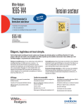
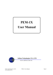
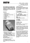
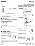
1E65-144
Non-programmable Electronic Digital Thermostat
For Line Voltage Applications
INSTALLATION AND OPERATION INSTRUCTIONS
Operator: Save these instructions for future use!
DESCRIPTION
The 1E65-144 thermostat has been designed to control electric heating
systems such as baseboard heaters, radiant floors, radiant ceilings
and convectors.
The adapter plate is used to offset the thermostat when an obstruction
prevents the thermostat from being mounted directly to the junction
box.
Temperature
Adjustment
Buttons
Temperature
Display
Light
Button
The thermostat cannot be used with the following:
- a resistive load under 2 A
- a resistive load over 16.7 A
- systems driven by a contactor or a relay (inductive load)
- central heating systems
Parts Supplied:
One (1) thermostat
Two (2) 6-32 pan head screws
System
Switch
Available Accessories:
F61-2642 Adapter Plate
SPECIFICATIONS
Supply:
120/240 VAC, 50/60 Hz
Minimum load: 2 A (resistive only)
500 W @ 240 VAC
250 W @ 120 VAC
Maximum load: 16.7 A (resistive only)
4000 W @ 240 VAC
2000 W @ 120 VAC
Setpoint range:
Display range:
Display resolution:
Shipping:
Approval:
7°C to 32°C (45°F to 90°F)
0°C to 37°C (32°F to 99°F)
0.1°C (1°F)
–20°C to 50°C (-4°F to 120°F)
PRECAUTIONS
!
WARNING
* Failure to read and follow all instructions carefully before
installing or operating this control could cause personal injury
and/or property damage.
* All wiring must conform to local and national electrical
codes and ordinances.
* To prevent electrical shock, personal injury, and/or equipment
damage, disconnect electric power to system at main fuse or
circuit breaker box prior to installation or service.
INSTALLATION
Installation should be done by a qualified heating and air conditioning
contractor or licensed electrician.
Loosen the screw holding the thermostat cover to the base, open cover
on hinge and remove the cover.
Optional: Use the adapter plate accessory if you need to offset the
mounting holes on the junction box. Align and affix the wall plate to
the electrical junction box using two 6-32 flat head screws included
with the plate.
Screw
White-Rodgers is a division
of Emerson Electric Co.
www.white-rodgers.com
PART NO. 37-6862D
Replaces 37-6862C
0839
INSTALLATION (cont.)
NOTE
Use with copper conductors only. Use wire connectors approved for 12 AWG only.
Make the appropriate connections to the thermostat as per diagram
below. The wires are non-polarized so either wire can be connected
to either terminal.
4 Wire Installation
2 Wire Installation
CAUTION
Keep the air vents of the thermostat clean and unobstructed at all times. Failure to do so can cause harm to your
thermostat.
Align and affix the base to the electrical junction box or the optional
adapter plate using two 6-32 pan head screws.
Place the thermostat cover back onto the base hinge and close cover.
Install screw to secure cover.
OPERATION
Slide thermostat switch to position. The thermostat normally displays
the actual ambient temperature.
Default
Backlight
Display Reading Adjustment*
Proportional Control**
Anticipation***
Temperature Scale
The thermostat displays the percentage of power usage (in "PC" mode
only) required to maintain the desired temperature. For example:
100% power usage
70% power usage
or
L3.0 to H3.0
PO (On)
PF (Off)
AL(2000-4000 W)
AS (500-2000 W)
SC (Celsius)
SF (Fahrenheit)
* Adjusts room temperature display higher or lower to agree with a
previous thermostat.
** Proportional Control allows the thermostat to modulate depending
on power usage.
***Adjusts your thermostat anticipation based on the room and baseboard heater size, e.g., in a room with a 3500 W baseboard heater,
set your thermostat anticipation to AL.
,
, and
buttons
To suspend the thermostat operation, slide the thermostat switch to
the
position. In this position, the thermostat still has power but the
display is turned off.
button
To change the thermostat installer configuration, press and hold the
button for 5 seconds. The features and (defaults) are selected by
pressing the
button once to scan the installer configuration selections. The defaults are changed with the
or
button. (Please refer
to the following table for the selections of your choice.)
The Emerson logo is a
trademark and a service mark
of Emerson Electric Co.
LF (Off)
H0.0
To reset the thermostat, press the
simultaneously.
To view the setpoint temperature, press the
or
button once. The
icon appears and the thermostat displays the setpoint temperature.
To change the setpoint, press the
or
button to raise or lower the
temperature until the desired setpoint is reached.
button, or the
LO (On)
The thermostat will save the setpoint temperature and installer configuration selections permanently, even after power outages.
30% power usage
To turn the backlight on, press the
once.
Options
Heating Element Thermal Protection
Most heating elements have a protection device that activates when
overheated. It is possible that if the device is worn out, it becomes
more sensitive. This device has a chance of being activated when
the heating element is on for a long period of time. When the thermal
protection is activated, the electrical power ceases to supply the
thermostat, and its display is turned off for a few minutes. The same
phenomenon exists with a mechanical thermostat but nothing could
indicate it. A thermal protection that opens too often can cause the
thermostat to poorly regulate temperature and should be replaced by
an electrician or the heating element manufacturer.
1E65-144
Thermostat numérique électronique non programmable
pour installations à la tension du réseau
DIRECTIVES D’INSTALLATION
ET D’UTILISATION
Utilisateur : Conserver ces directives à titre de référence!
DESCRIPTION
Le thermostat 1E65-144 est conçu pour commander les systèmes de
chauffage électriques, notamment : plinthes chauffantes, planchers
radiants, plafonds radiants et convecteurs.
La plaque adaptatrice sert à décaler le thermostat lorsqu’une obstruction
empêche de l’installer directement sur la boîte de raccordement.
Touches de
réglage du point
de consigne
Afficheur
Touche
d’illumination
Le thermostat ne peut être utilisé avec :
- une charge résistive inférieure à 2 A
- une charge résistive supérieure à 16,7 A
- les installations commandées par un contacteur ou un relais
(charge inductive)
- les installations de chauffage central
Commutateur
système
Pièces fournies :
Accessoires proposés :
Un (1) thermostat
Plaque adaptatrice F61-2642
Deux (2) vis 6-32 à tête cylindrique bombée
SPÉCIFICATIONS
Alimentation :
Charge minimale :
Charge maximale :
120/240 V CA, 50/60 Hz
2 A (résistive seulement)
500 W @ 240 V CA
250 W @ 120 V CA
16,7 A (résistive seulement)
4000 W @ 240 V CA
2000 W @ 120 V CA
Points de consigne :
Températures affichées :
Résolution d’affichage :
Expédition :
Homologation :
7 °C à 32 °C (45 °F à 90 °F)
0 °C à 37 °C (32 °F à 99 °F)
0,1 °C (1 °F)
–20 °C à 50 °C (–4 °F à 120 °F)
PRÉCAUTIONS
!
MISE EN GARDE
* Prière de lire et de suivre attentivement toutes les directives
avant d’installer ou d’utiliser la commande, sans quoi des
blessures et des dommages matériels risquent de survenir.
* Tout le câblage doit respecter les codes de l'électricité et
règlements en vigueur.
* Afin de prévenir les décharges électriques, les blessures
et les dommages matériels, couper l’alimentation électrique
au panneau de distribution principal avant les travaux
d’installation ou de révision.
INSTALLATION
L'installation doit être effectuée par un maître électricien ou par un
entrepreneur en chauffage et climatisation reconnu.
Desserrerr la vis qui fixe le boîtier au socle du thermostat, puis pivoter
le boîtier sur sa charnière et le détacher.
Facultatif : Utiliser la plaque adaptatrice accessoire s’il est nécessaire
de décaler les trous de montage de la boîte de raccordement. Aligner
la plaque sur la boîte de raccordement électrique et la fixer à l’aide des
deux vis 6-32 à tête plate fournies avec la plaque.
Vis
White-Rodgers est une division
d’Emerson Electric Co.
www.white-rodgers.com
PIÈCE No 37-6862D
Remplace 37-6862C
0839
INSTALLATION (suite)
NOTA
Utiliser exclusivement des conducteurs de cuivre. Utiliser exclusivement des capuchons de connexion homologués pour les conducteurs de calibre 12 AWG.
Câbler le thermostat en suivant le schéma ci-dessous. Les fils ne sont pas
polarisés ; on peut donc les brancher sur l’une ou l’autre des bornes.
Installation à 4 fils
Installation à 2 fils
ATTENTION
Faire en sorte que les prises d’air du thermostat soient en tout
temps propres et libres de toute obstruction, à défaut de quoi
le thermostat risque de subir des dommages.
Aligner la base sur la boîte de raccordement électrique ou sur la plaque adaptatrice facultative et la fixer à l’aide des deux vis 6-32 à tête
cylindrique bombée.
Replacer le boîtier du thermostat sur sa charnière et le refermer. Poser
la vis qui retient le boîtier.
UTILISATION
Régler le commutateur du thermostat à la position . Le thermostat
devrait normalement afficher la température ambiante.
Par défaut
Réglages
LO (Marche)
LF (Arrêt)
H0.0
L3.0 à H3.0
Système de réglage proportionnel
PO (Marche)
PF (Arrêt)
Anticipation***
AL
(2000-4000 W)
AS
(500-2000 W)
Échelle de température
SC (Celsius)
SF (Fahrenheit)
Illumination de l’afficheur
Réglage de la
température affichée
Réglé au mode PC, le thermostat affiche le pourcentage de consommation électrique nécessaire pour maintenir la température désirée.
Par exemple :
100 % de consommation électrique
70 % de consommation électrique
30 % de consommation électrique
Pour afficher le point de consigne, appuyer brièvement sur la touche
ou . L’icone
s’affiche ainsi que le point de consigne. Pour modifier
le point de consigne, appuyer sur la touche ou afin de hausser ou
de baisser la température affichée.
Pour illuminer l’afficheur, appuyer sur la touche
fois sur la touche
ou .
ou appuyer une seule
Pour régler les paramètres de configuration, tenir la touche enfoncée
pendant 5 secondes. Utiliser la touche
pour faire défiler les différents
réglages. Pour en modifier un, utiliser la touche
ou . (Le tableau
ci-dessous indique les réglages possibles.)
Le logo Emerson est une marque
de commerce et de service
d’Emerson Electric Co.
* Réglage à la hausse ou à la baisse de l’affichage de la température ambiante pour la faire correspondre à un ancien thermostat.
** Système de réglage proportionnel qui fait moduler la consommation électrique du thermostat.
*** Réglage de l'anticipation du thermostat en fonction de la taille de
la pièce et de la plinthe chauffante : p. ex., dans une pièce dotée
d'une plinthe de 3500 W, régler l'anticipation sur AL
Le thermostat stocke le point de consigne et les réglages dans une
mémoire permanente qui survit même aux pannes de courant.
Pour réinitialiser le thermostat, appuyer simultanément sur les touches
,
et .
Pour interrompre le fonctionnement du thermostat, régler le commutateur
à la position . Le thermostat continue alors d’être alimenté, mais son
afficheur s’éteint.
Protection thermique des éléments chauffants
La plupart des éléments chauffants sont dotés d’un dispositif de
protection qui s’enclenche lors d’une surchauffe. Lorsqu’il est usé,
ce dispositif devient parfois plus sensible. Il risque alors de se
déclencher si l’élément chauffant fonctionne pendant une longue
période. Une fois ce dispositif enclenché, le thermostat cesse d’être
alimenté et son afficheur s’éteint pendant quelques minutes. Le
même phénomène se produit chez les thermostats mécaniques
sans que l’utilisateur le sache. Si le dispositif de protection thermique
s’enclenche trop souvent, il est possible que le thermostat cesse de
régler correctement la température; on doit alors faire remplacer le
dispositif par un électricien ou par le fabricant de l’élément chauffant.