1
VSX_AX4AVi.book.fm 1 ページ 2005年6月20日 月曜日 午後6時27分
VSX-AX4AVi-S
VSX-AX2AV-S
AUDIO/VIDEO MULTI-CHANNEL RECEIVER
Discover the benefits of registering your product online at www.pioneer.co.uk
(www.pioneer-eur.com).
Operating Instructions
VSX_AX4AVi.book.fm 2 ページ 2005年6月20日 月曜日 午後6時27分
IMPORTANT
CAUTION
RISK OF ELECTRIC SHOCK
DO NOT OPEN
The lightning flash with arrowhead symbol,
within an equilateral triangle, is intended to
alert the user to the presence of uninsulated
"dangerous voltage" within the product's
enclosure that may be of sufficient
magnitude to constitute a risk of electric
shock to persons.
CAUTION:
TO PREVENT THE RISK OF ELECTRIC
SHOCK, DO NOT REMOVE COVER (OR
BACK). NO USER-SERVICEABLE PARTS
INSIDE. REFER SERVICING TO QUALIFIED
SERVICE PERSONNEL.
The exclamation point within an equilateral
triangle is intended to alert the user to the
presence of important operating and
maintenance (servicing) instructions in the
literature accompanying the appliance.
D3-4-2-1-1_En-A
Replacement and mounting of an AC plug on the power supply cord of this unit should be performed only by qualified
service personnel.
IMPORTANT
FOR USE IN THE UNITED
KINGDOM
The wires in this mains lead are coloured in
accordance with the following code:
Blue
: Neutral
Brown : Live
If the plug provided is unsuitable for your socket
outlets, the plug must be cut off and a suitable plug
fitted.
The cut-off plug should be disposed of and must
not be inserted into any 13 amp socket as this can
result in electric shock. The plug or adaptor or the
distribution panel should be provided with 10 A
fuse. As the colours of the wires in the mains lead
of this appliance may not correspond with coloured
markings identifying the terminals in your plug,
proceed as follows ;
The wire which is coloured blue must be connected
to the terminal which is marked with the letter N or
coloured black.
The wire which is coloured brown must be
connected to the terminal which is marked with the
letter L or coloured red.
Thank you for buying this Pioneer product.
Please read through these operating
instructions so you will know how to operate
your model properly. After you have finished
reading the instructions, put them away in a
safe place for future reference.
WARNING
Before plugging in for the first time, read the following
section carefully.
The voltage of the available power supply differs
according to country or region. Be sure that the
power supply voltage of the area where this unit
will be used meets the required voltage (e.g., 230V
D3-4-2-1-4_A_En
or 120V) written on the rear panel.
WARNING
To prevent a fire hazard, do not place any naked
flame sources (such as a lighted candle) on the
D3-4-2-1-7a_A_En
equipment.
This product complies with the Low Voltage Directive
(73/23/EEC, amended by 93/68/EEC), EMC Directives
(89/336/EEC, amended by 92/31/EEC and
D3-4-2-1-9a_En
93/68/EEC).
Do not connect either wire to the earth terminal of a
three pin plug.
NOTE
After replacing or changing a fuse, the fuse cover in
the plug must be replaced with a fuse cover which
corresponds to the colour of the insert in the base
of the plug or the word that is embossed on the
base of the plug, and the appliance must not be
used without a fuse cover. If lost replacement fuse
covers can be obtained from your dealer.
Only 10 A fuses approved by B.S.I or A.S.T.A to
B.S.1362 should be used.
D3-4-2-1-2-2_En
WARNING
This equipment is not waterproof. To prevent a fire
or shock hazard, do not place any container filled
with liquid near this equipment (such as a vase or
flower pot) or expose it to dripping, splashing, rain
D3-4-2-1-3_A_En
or moisture.
VENTILATION CAUTION
When installing this unit, make sure to leave space
around the unit for ventilation to improve heat
radiation (at least 60 cm at top, 10 cm at rear, and
30 cm at each side).
WARNING
Slots and openings in the cabinet are provided for
ventilation to ensure reliable operation of the
product, and to protect it from overheating. To
prevent fire hazard, the openings should never be
blocked or covered with items (such as newspapers,
table-cloths, curtains) or by operating the
D3-4-2-1-7b_A_En
equipment on thick carpet or a bed.
VSX_AX4AVi.book.fm 3 ページ 2005年6月20日 月曜日 午後6時27分
If the AC plug of this unit does not match the AC
outlet you want to use, the plug must be removed
and appropriate one fitted. Replacement and
mounting of an AC plug on the power supply cord of
this unit should be performed only by qualified
service personnel. If connected to an AC outlet, the
cut-off plug can cause severe electrical shock. Make
sure it is properly disposed of after removal.
The equipment should be disconnected by removing
the mains plug from the wall socket when left
unused for a long period of time (for example, when
D3-4-2-2-1a_A_En
on vacation).
CAUTION
The STANDBY/ON switch on this unit will not
completely shut off all power from the AC outlet.
Since the power cord serves as the main disconnect
device for the unit, you will need to unplug it from
the AC outlet to shut down all power. Therefore,
make sure the unit has been installed so that the
power cord can be easily unplugged from the AC
outlet in case of an accident. To avoid fire hazard,
the power cord should also be unplugged from the
AC outlet when left unused for a long period of time
(for example, when on vacation).
D3-4-2-2-2a_A_En
When disposing of used batteries, please comply
with governmental regulations or
environmental public instruction’s rules that
D3-4-2-3-1_En
apply in your country/area.
Operating Environment
Operating environment temperature and humidity:
+5 ºC – +35 ºC (+41 ºF – +95 ºF); less than 85 %RH
(cooling vents not blocked)
Do not install this unit in a poorly ventilated area, or in
locations exposed to high humidity or direct sunlight (or
D3-4-2-1-7c_A_En
strong artificial light)
This product is for general household purposes. Any
failure due to use for other than household purposes
(such as long-term use for business purposes in a
restaurant or use in a car or ship) and which
requires repair will be charged for even during the
K041_En
warranty period.
CAUTION
These speaker terminals carry HAZARDOUS LIVE
voltage. To prevent the risk of electric shock when
connecting or disconnecting the speaker cables,
disconnect the power cord before touching any
D3-4-2-2-3_A_En
uninsulated parts.
Important information about this unit‘s AC outlets
Switched total 100 W MAX
Power supplied through these outlets is turned on and off by this unit’s STANDBY/ON switch. Total electrical
power consumption of connected equipment should not exceed 100 W.
CAUTION
• Do not connect a TV set, monitor, heater or similar appliance to this unit’s AC outlet.
• Do not connect appliances with high power consumption to the AC outlet in order to avoid overheating and fire
D3-4-2-2-1b_A_En
risk. This can cause this unit to malfunction.
VSX_AX4AVi.book.fm 4 ページ 2005年6月20日 月曜日 午後6時27分
Contents
01 Before you start
05 Listening to your system
Checking what’s in the box . . . . . . . . . . . . . . . . . . . . . . . 6
Installing the receiver . . . . . . . . . . . . . . . . . . . . . . . . . . . 6
Loading the batteries. . . . . . . . . . . . . . . . . . . . . . . . . . . . 6
Auto playback . . . . . . . . . . . . . . . . . . . . . . . . . . . . . . . .
Listening in surround sound . . . . . . . . . . . . . . . . . . . .
Standard surround sound . . . . . . . . . . . . . . . . . . . . .
Using the Home THX modes . . . . . . . . . . . . . . . . . . .
Using the Advanced surround effects . . . . . . . . . . .
Listening in stereo. . . . . . . . . . . . . . . . . . . . . . . . . . . . .
Using Stream Direct . . . . . . . . . . . . . . . . . . . . . . . . . . .
Selecting MCACC presets . . . . . . . . . . . . . . . . . . . . . .
Choosing the input signal . . . . . . . . . . . . . . . . . . . . . .
Using surround back channel processing . . . . . . . . .
Using the Virtual Surround Back mode . . . . . . . . . .
02 5 minute guide
Introduction to home theater . . . . . . . . . . . . . . . . . . . . . 7
Listening to Surround Sound . . . . . . . . . . . . . . . . . . . . . 7
Automatically setting up for surround sound
(MCACC) . . . . . . . . . . . . . . . . . . . . . . . . . . . . . . . . . . . . . . 7
Problems when using the Auto MCACC Setup . . . . . 9
Playing a source. . . . . . . . . . . . . . . . . . . . . . . . . . . . . . . . 9
Better sound using Phase Control . . . . . . . . . . . . . . . . . 9
26
26
26
27
27
28
28
28
28
29
29
06 Using the tuner
03 Connecting your equipment
Rear panel . . . . . . . . . . . . . . . . . . . . . . . . . . . . . . . . . . . 10
When making cable connections. . . . . . . . . . . . . . . . . 11
About the video converter . . . . . . . . . . . . . . . . . . . . . . . 11
Connecting your TV and DVD player . . . . . . . . . . . . . . 12
Connecting a satellite/cable receiver or other
set-top box . . . . . . . . . . . . . . . . . . . . . . . . . . . . . . . . . . . 13
Connecting a DVD/HDD recorder, VCR and
other video sources . . . . . . . . . . . . . . . . . . . . . . . . . . . . 13
Using the component video jacks . . . . . . . . . . . . . . . . 14
Connecting digital audio sources . . . . . . . . . . . . . . . . 15
About the WMA9 Pro decoder . . . . . . . . . . . . . . . . . . 15
Connecting analog audio sources . . . . . . . . . . . . . . . . 16
Connecting a component to the front panel
inputs . . . . . . . . . . . . . . . . . . . . . . . . . . . . . . . . . . . . . . . 16
Installing your speaker system . . . . . . . . . . . . . . . . . . . 17
Connecting the speakers . . . . . . . . . . . . . . . . . . . . . . 17
Placing the speakers. . . . . . . . . . . . . . . . . . . . . . . . . . 18
THX speaker system setup . . . . . . . . . . . . . . . . . . . . . 19
Connecting antennas . . . . . . . . . . . . . . . . . . . . . . . . . . 19
AM loop antenna . . . . . . . . . . . . . . . . . . . . . . . . . . . . . 19
FM wire antenna . . . . . . . . . . . . . . . . . . . . . . . . . . . . . 20
Connecting external antennas . . . . . . . . . . . . . . . . . . 20
Plugging in the receiver . . . . . . . . . . . . . . . . . . . . . . . . 20
AC outlet . . . . . . . . . . . . . . . . . . . . . . . . . . . . . . . . . . . . . 20
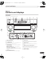
04 Controls and displays
Front panel . . . . . . . . . . . . . . . . . . . . . . . . . . . . . . . . . . . 21
Operating range of remote control unit . . . . . . . . . . 22
Display . . . . . . . . . . . . . . . . . . . . . . . . . . . . . . . . . . . . . . 23
Remote control. . . . . . . . . . . . . . . . . . . . . . . . . . . . . . . . 24
Listening to the radio . . . . . . . . . . . . . . . . . . . . . . . . . .
Improving FM stereo sound. . . . . . . . . . . . . . . . . . . .
Tuning directly to a station . . . . . . . . . . . . . . . . . . . .
Saving station presets . . . . . . . . . . . . . . . . . . . . . . . . .
Naming station presets . . . . . . . . . . . . . . . . . . . . . . .
Listening to station presets . . . . . . . . . . . . . . . . . . . .
An introduction to RDS . . . . . . . . . . . . . . . . . . . . . . . .
Searching for RDS programs . . . . . . . . . . . . . . . . . .
Using EON . . . . . . . . . . . . . . . . . . . . . . . . . . . . . . . . . . .
07 The System Setup menu
Making receiver settings from the System
Setup menu . . . . . . . . . . . . . . . . . . . . . . . . . . . . . . . . . .
Automatic MCACC (Expert) . . . . . . . . . . . . . . . . . . . . .
Surround back speaker setting . . . . . . . . . . . . . . . . . .
Manual MCACC setup . . . . . . . . . . . . . . . . . . . . . . . . .
Fine Channel Level . . . . . . . . . . . . . . . . . . . . . . . . . . .
Fine Speaker Distance . . . . . . . . . . . . . . . . . . . . . . . .
Standing Wave . . . . . . . . . . . . . . . . . . . . . . . . . . . . . .
Acoustic Calibration EQ. . . . . . . . . . . . . . . . . . . . . . .
Professional Acoustic Calibration EQ . . . . . . . . . . .
Data Management . . . . . . . . . . . . . . . . . . . . . . . . . . . .
Manual speaker setup . . . . . . . . . . . . . . . . . . . . . . . . .
Speaker Setting . . . . . . . . . . . . . . . . . . . . . . . . . . . . .
Channel Level . . . . . . . . . . . . . . . . . . . . . . . . . . . . . . .
Speaker Distance . . . . . . . . . . . . . . . . . . . . . . . . . . . .
Bass Peak Level . . . . . . . . . . . . . . . . . . . . . . . . . . . . .
X-Curve . . . . . . . . . . . . . . . . . . . . . . . . . . . . . . . . . . . .
THX Audio Setting . . . . . . . . . . . . . . . . . . . . . . . . . . .
4
33
33
35
36
36
37
37
38
38
41
42
42
43
44
44
45
45
08 Other connections
Connecting an iPod . . . . . . . . . . . . . . . . . . . . . . . . . . .
Connecting your iPod to the receiver . . . . . . . . . . . .
Playing music from your iPod . . . . . . . . . . . . . . . . . .
Connecting using HDMI. . . . . . . . . . . . . . . . . . . . . . . .
About HDMI. . . . . . . . . . . . . . . . . . . . . . . . . . . . . . . . . .
En
30
30
30
30
31
31
31
31
32
46
46
46
47
48
VSX_AX4AVi.book.fm 5 ページ 2005年6月20日 月曜日 午後6時27分
Using the i.LINK interface. . . . . . . . . . . . . . . . . . . . . . . 48
Checking the i.LINK inputs . . . . . . . . . . . . . . . . . . . . 49
About i.LINK . . . . . . . . . . . . . . . . . . . . . . . . . . . . . . . . . . 49
About PQLS rate control . . . . . . . . . . . . . . . . . . . . . . 50
Creating an i.LINK network . . . . . . . . . . . . . . . . . . . . 50
Connecting the multichannel analog inputs . . . . . . . 51
Selecting the multichannel analog inputs . . . . . . . . 51
Using the USB interface . . . . . . . . . . . . . . . . . . . . . . . . 51
Second Zone speaker B setup . . . . . . . . . . . . . . . . . . . 52
Switching the speaker system . . . . . . . . . . . . . . . . . . 52
Bi-amping your front speakers . . . . . . . . . . . . . . . . . . . 53
Bi-wiring your speakers. . . . . . . . . . . . . . . . . . . . . . . . . 53
Connecting additional amplifiers . . . . . . . . . . . . . . . . . 54
Multi-room listening . . . . . . . . . . . . . . . . . . . . . . . . . . . 54
Making multi-room connections . . . . . . . . . . . . . . . . 54
Using the multi-room controls. . . . . . . . . . . . . . . . . . 56
Connecting an IR receiver . . . . . . . . . . . . . . . . . . . . . . 56
Switching components on and off using the
12 volt trigger . . . . . . . . . . . . . . . . . . . . . . . . . . . . . . . . . 57
Using this receiver with a Pioneer plasma
display. . . . . . . . . . . . . . . . . . . . . . . . . . . . . . . . . . . . . . . 57
Using the SR+ mode with a Pioneer plasma
display. . . . . . . . . . . . . . . . . . . . . . . . . . . . . . . . . . . . . . . 58
Connecting a PC for Advanced MCACC output . . . . . 59
Advanced MCACC output using your PC . . . . . . . . . 59
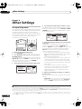
09 Other Settings
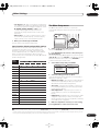
The Input Setup menu. . . . . . . . . . . . . . . . . . . . . . . . . . 60
Input function default and possible settings . . . . . . 61
The Other Setup menu . . . . . . . . . . . . . . . . . . . . . . . . . 61
Multi-Room and IR receiver setup . . . . . . . . . . . . . . . 62
SR+ Setup for Pioneer plasma displays. . . . . . . . . . 62
OSD Adjustment . . . . . . . . . . . . . . . . . . . . . . . . . . . . . 62
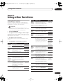
10 Using other functions
Setting the AV options. . . . . . . . . . . . . . . . . . . . . . . . . . 63
Making an audio or a video recording . . . . . . . . . . . . . 64
Playing a different source when recording. . . . . . . . 64
Reducing the level of an analog signal . . . . . . . . . . . . 65
Watching video and audio sources independently . . 65
Using the sleep timer . . . . . . . . . . . . . . . . . . . . . . . . . . 65
Dimming the display . . . . . . . . . . . . . . . . . . . . . . . . . . . 65
Switching the speaker impedance. . . . . . . . . . . . . . . . 65
Checking your system settings. . . . . . . . . . . . . . . . . . . 65
Resetting the system . . . . . . . . . . . . . . . . . . . . . . . . . . . 66
Default system settings . . . . . . . . . . . . . . . . . . . . . . . 66
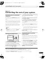
11 Controlling the rest of your system
Setting the remote to control other components . . .
Selecting preset codes directly . . . . . . . . . . . . . . . . . .
Programming signals from other remote
controls . . . . . . . . . . . . . . . . . . . . . . . . . . . . . . . . . . . . .
Erasing one of the remote control button
settings . . . . . . . . . . . . . . . . . . . . . . . . . . . . . . . . . . . . .
Resetting the remote control presets . . . . . . . . . . . . .
Confirming preset codes . . . . . . . . . . . . . . . . . . . . . . .
Renaming input source names . . . . . . . . . . . . . . . . . .
Direct function . . . . . . . . . . . . . . . . . . . . . . . . . . . . . . .
Multi Operation and System Off . . . . . . . . . . . . . . . . .
Programming a multi-operation or a shutdown
sequence. . . . . . . . . . . . . . . . . . . . . . . . . . . . . . . . . . .
Using multi operations . . . . . . . . . . . . . . . . . . . . . . .
Using System off . . . . . . . . . . . . . . . . . . . . . . . . . . . .
Controls for TVs . . . . . . . . . . . . . . . . . . . . . . . . . . . . . . .
Controls for other components . . . . . . . . . . . . . . . . . .
Operating other Pioneer components with this
unit’s sensor . . . . . . . . . . . . . . . . . . . . . . . . . . . . . . . . .
67
67
67
68
68
68
69
69
69
69
70
70
71
71
72
12 Additional information
Troubleshooting . . . . . . . . . . . . . . . . . . . . . . . . . . . . . .
Power. . . . . . . . . . . . . . . . . . . . . . . . . . . . . . . . . . . . . .
No sound. . . . . . . . . . . . . . . . . . . . . . . . . . . . . . . . . . .
Other audio problems . . . . . . . . . . . . . . . . . . . . . . . .
Video . . . . . . . . . . . . . . . . . . . . . . . . . . . . . . . . . . . . . .
Settings . . . . . . . . . . . . . . . . . . . . . . . . . . . . . . . . . . . .
Display. . . . . . . . . . . . . . . . . . . . . . . . . . . . . . . . . . . . .
Remote control . . . . . . . . . . . . . . . . . . . . . . . . . . . . . .
i.LINK interface. . . . . . . . . . . . . . . . . . . . . . . . . . . . . .
i.LINK messages. . . . . . . . . . . . . . . . . . . . . . . . . . . . .
USB interface . . . . . . . . . . . . . . . . . . . . . . . . . . . . . . .
HDMI . . . . . . . . . . . . . . . . . . . . . . . . . . . . . . . . . . . . . .
iPod messages . . . . . . . . . . . . . . . . . . . . . . . . . . . . . .
Surround sound formats . . . . . . . . . . . . . . . . . . . . . . .
Dolby . . . . . . . . . . . . . . . . . . . . . . . . . . . . . . . . . . . . . .
DTS . . . . . . . . . . . . . . . . . . . . . . . . . . . . . . . . . . . . . . .
Windows Media® Audio 9 Professional . . . . . . . . .
About THX . . . . . . . . . . . . . . . . . . . . . . . . . . . . . . . . . . .
Listening modes with different input signal
formats. . . . . . . . . . . . . . . . . . . . . . . . . . . . . . . . . . . . . .
Stream direct with different input signal formats . . .
Specifications . . . . . . . . . . . . . . . . . . . . . . . . . . . . . . . .
Cleaning the unit. . . . . . . . . . . . . . . . . . . . . . . . . . . . . .
Our philosophy . . . . . . . . . . . . . . . . . . . . . . . . . . . . . . .
Features. . . . . . . . . . . . . . . . . . . . . . . . . . . . . . . . . . . .
73
73
73
74
75
75
76
77
77
78
78
78
79
80
80
80
80
81
82
84
85
85
86
86
5
En
VSX_AX4AVi.book.fm 6 ページ 2005年6月20日 月曜日 午後6時27分
01
Before you start
Chapter 1:
Before you start
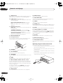
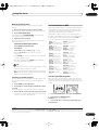
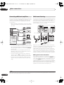
Checking what’s in the box
Loading the batteries
Please check that you've received the following supplied
accessories:
• Setup microphone (cable: 5m.)
• Remote control unit
• AA/LR6 dry cell batteries x2
• AM loop antenna
• FM wire antenna
• Power cord
• Caution sheet
• Warranty card
• These operating instructions
Installing the receiver
• When installing this unit, make sure to put it on a
level and stable surface.
Don’t install it on the following places:
– on a color TV (the screen may distort)
– near a cassette deck (or close to a device that gives off
a magnetic field). This may interfere with the sound.
– in direct sunlight
– in damp or wet areas
– in extremely hot or cold areas
– in places where there is vibration or other movement
– in places that are very dusty
– in places that have hot fumes or oils (such as a kitchen)
6
En
Caution
Incorrect use of batteries may result in such hazards as
leakage and bursting. Observe the following precautions:
• Never use new and old batteries together.
• Insert the plus and minus sides of the batteries
properly according to the marks in the battery case.
• Batteries with the same shape may have different
voltages. Do not use different batteries together.
• When disposing of used batteries, please comply
with governmental regulations or environmental
public instruction’s rules that apply in your country or
area.
VSX_AX4AVi.book.fm 7 ページ 2005年6月20日 月曜日 午後6時27分
5 minute guide
02
Chapter 2:
5 minute guide
Introduction to home theater
Home theater refers to the use of multiple audio tracks to
create a surround sound effect, making you feel like
you're in the middle of the action or concert. The
surround sound you get from a home theater system
depends not only on your speaker setup, but also on the
source and the sound settings of the receiver.
This receiver will automatically decode multichannel
Dolby Digital, DTS, or Dolby Surround sources according
to your speaker setup. In most cases, you won’t have to
make changes for realistic surround sound, but other
possibilities (like listening to a CD with multichannel
surround sound) are explained in Listening to your
system on page 26.
Listening to Surround Sound
This receiver was designed with the easiest possible
setup in mind, so with the following quick setup guide,
you should have your system hooked up for surround
sound in no time at all. In most cases, you can simply
leave the receiver in the default settings.
• Be sure to complete all connections before
connecting this unit to an AC power source.
1 Connect your TV and DVD player.
See Connecting your TV and DVD player on page 12 to do
this. For surround sound, you’ll want to hook up using a
digital connection from the DVD player to the receiver.
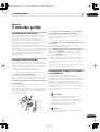
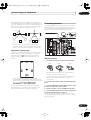
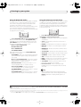
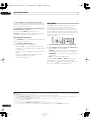
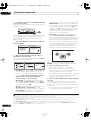
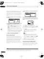
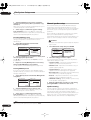
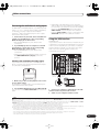
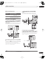
2 Connect your speakers and place them for optimal
surround sound.
Connect your speakers as shown in Installing your
speaker system on page 17.
Where you place the speakers will have a big effect on the
sound. Place your speakers as shown below for the best
surround sound effect. Also see Placing the speakers on
page 18 for more on this.
Center (C)
Front
Left (L)
• Set the subwoofer volume to a comfortable level.
4 Use the on-screen automatic MCACC setup to set up
your system.
See Automatically setting up for surround sound
(MCACC) below for more on this.
5 Play a DVD, and adjust the volume to your liking.
Make sure that DVD/LD is showing in the receiver’s
display, indicating that the DVD input is selected. If it
isn’t, press DVD/LD on the remote control to set the
receiver to the DVD input.
In addition to the basic playback explained in Playing a
source on page 9, there are several other sound options
you can select. See Listening to your system on page 26
for more on this.
See also Making receiver settings from the System Setup
menu on page 33 for more setup options.
Automatically setting up for surround
sound (MCACC)
The Auto MCACC Setup measures the acoustic
characteristics of your listening area, taking into account
ambient noise, speaker size and distance, and tests for
both channel delay and channel level. After you have set
up the microphone provided with your system, the
receiver uses the information from a series of test tones
to optimize the speaker settings and equalization for your
particular room.
Make sure you do this before moving on to Playing a
source on page 9.
Important
• Make sure the microphone and speakers are not
moved during the Auto MCACC Setup.
Front
Right (R)
Subwoofer (SW)
3 Plug in the receiver and switch it on, followed by
your DVD player, your subwoofer and the TV.
Make sure you’ve set the video input on your TV to this
receiver. Check the manual that came with the TV if you
don’t know how to do this.
Surround
Right (SR)
• Using the Auto MCACC Setup will overwrite any
existing settings for the MCACC preset you select.
• Before using the Auto MCACC Setup the
headphones should be disconnected.
Surround
Back
Right (SBR)
Listening
position
Surround
Left (SL)
Surround
Back Left (SBL)
Caution
• The test tones used in the Auto MCACC Setup are
output at high volume.
7
En
VSX_AX4AVi.book.fm 8 ページ 2005年6月20日 月曜日 午後6時27分
5 minute guide
02
SYSTEM OFF
RECEIVER
INPUT
SELECT
SOURCE
D.ACCESS
+10
CLASS
DISC
ENTER
AV PARAMETER
TOP MENU CH LEVEL
MENU
T.EDIT
ENTER
SETUP
GUIDE
1
CD
TV
VIDEO 2
DVD
SAT
VIDEO 1
RETURN
PTY SEARCH
BAND
TV CONTROL
TV CONT
DVR2
CD-R
MULTI IN
ROOM2/3
DVR1
i Pod
TUNER
RECEIVER
TV VOL
INPUT
SELECT
TV CH
VOL
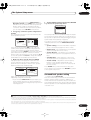
Switch on the receiver and your TV.
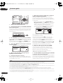
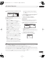
2 Connect the microphone to the MCACC SETUP MIC
jack on the front panel.
Place the microphone so that it’s about ear level at your
normal listening position (use a tripod if possible). Make
sure there are no obstacles between the speakers and
the microphone.
(TUNE +)
SPEAKERS
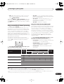
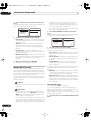
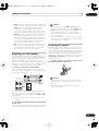
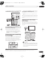
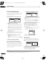
7 Wait for the test tones to finish then confirm the
speaker configuration in the OSD.
A progress report is displayed on-screen while the
receiver outputs test tones to determine the speakers
present in your setup. Try to be as quiet as possible while
it’s doing this.5
BAND
MULTI – ROOM &
SOURCE/REC SEL
CONTROL ON/OFF
VIDEO
SELECT
SIGNAL
SELECT
SBch
PROCESSING
• With error messages (such as Ambient Noise or
Microphone Check) select RETRY after checking for
ambient noise (see Problems when using the Auto
MCACC Setup below) and verifying the mic
connection. If there doesn’t seem to be a problem,
you can simply select GO NEXT and continue.
1.Auto MCACC
1.Auto MCACC
Now Analyzing …
Environment Check
Ambient Noise
Microphone
Speaker YES/NO
(2/9)
[ OK ]
[
]
[
]
Check!
Front
Center
Surround
SB
SUB W.
:Cancel
STEREO
[
[
[
[
[
YES
YES
YES
Yx2
YES
]
]
]
]
]
[ OK ]
:Cancel
TUNER
EDIT
AV
PARAMETER
VIDEO/GAME 2 INPUT
PHONES
(ST –)
ENTER
SETUP
(ST +)
MCACC
SETUP MIC
RETURN
DIGITAL IN
(TUNE –)
S-VIDEO
VIDEO
The configuration shown on-screen should reflect the
actual speakers you have.6
L AUDIO R
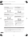
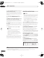
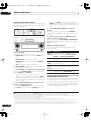
3 Press RECEIVER on the remote, then press SETUP.1
An on-screen display (OSD) appears on your TV. Use the
/// buttons and ENTER to navigate through the
screens and select menu items. Press RETURN to exit
the current menu. Press SETUP at any time to cancel.2
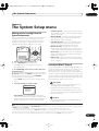
4 Select ‘Auto MCACC’ from the System Setup menu
then press ENTER.
System Setup
1.Auto MCACC
1.Auto MCACC
2.Surr Back System
3.Manual MCACC
4.Data Management
5.Manual SP Setup
6.Input Setup
7.Other Setup
Surr Back System
[
Normal (SB)
Data Save to
[M1. MEMORY 1
Setting Start?
]
]
[OK]
[Option]
: Exit
ENTER:Next
:Cancel
5 Make sure ‘Normal (SB)’ is selected,3 select an
MCACC preset4 then select OK.
6 Follow the instructions on-screen.
Make sure the microphone is connected, and if you’re
using a subwoofer, make sure it is switched on and set to
a comfortable volume level.
If you see an error message (ERR) in the right side
column (or the speaker configuration displayed isn’t
correct), there may be a problem with the speaker
connection. If selecting RETRY doesn’t work, turn off the
power and check the speaker connections. If there
doesn’t seem to be a problem, you can simply use /
to select the speaker and / to change the setting
(and number for surround back) and continue.
8 Make sure ‘OK’ is selected, then press ENTER.
A progress report is displayed on-screen while the
receiver outputs more test tones to determine the
optimum receiver settings for channel level, speaker
distance, and Acoustic Calibration EQ.
Again, try to be as quiet as possible while this is
happening. It may take 2–6 minutes.
9 The Auto MCACC Setup has finished! Press RETURN
to go back to the System Setup menu.7
The settings made in the Auto MCACC Setup should give
you excellent surround sound from your system, but it is
also possible to adjust these settings manually using the
System Setup menu (starting on page 33).8
Note
1 You can’t use the System Setup menu when the iPod input source is selected (in either the main or sub room).
2 If you cancel the Auto MCACC Setup, or leave an error message for over three minutes, the screen saver will appear.
3 • If you are planning on bi-amping your front speakers, or setting up a separate speaker system in another room, read through Surround back speaker
setting on page 35 and make sure to connect your speakers as necessary before continuing to step 6.
• If you have THX-certified speakers, select Option and choose YES for the THX Speaker setting.
4 The six MCACC presets are used for storing surround sound settings for different listening positions. Simply choose an unused preset for now
(you can rename it later in Data Management on page 41).
5 Do not adjust the volume during the test tones. This may result in incorrect speaker settings.
6 If you’re using the front panel display, the diagram in Listening to Surround Sound above indicates (in bold) how each speaker is displayed.
7 You can also choose to view the settings from the MCACC Data Check screen. See Automatic MCACC (Expert) on page 33 for more on this.
8 • Depending on the characteristics of your room, sometimes identical speakers with cone sizes of around 12cm will end up with different size settings.
You can correct the setting manually using the Manual speaker setup on page 42.
• The subwoofer distance setting may be farther than the actual distance from the listening position. This setting should be accurate (taking delay and
room characteristics into account) and generally does not need to be changed.
8
En
VSX_AX4AVi.book.fm 9 ページ 2005年6月20日 月曜日 午後6時27分
5 minute guide
02
Problems when using the Auto MCACC Setup
If the room environment is not optimal for the Auto
MCACC Setup (too much background noise, echo off the
walls, obstacles blocking the speakers from the
microphone) the final settings may be incorrect. Check
for household appliances (air conditioner, fridge, fan,
etc.), that may be affecting the environment and switch
them off if necessary. If there are any instructions
showing in the front panel display, please follow them.
• Some older TVs may interfere with the operation of
the microphone. If this seems to be happening,
switch off the TV when doing the Auto MCACC Setup.
4 Use the volume control to adjust the volume level.
Turn down the volume of your TV so that all sound is
coming from the speakers connected to this receiver.
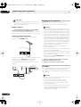
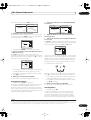
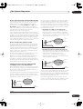
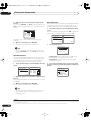
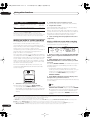
Better sound using Phase Control
This receiver’s Phase Control feature uses phase
correction measures to make sure your sound source
arrives at the listening position in phase, preventing
unwanted distortion and/or coloring of the sound (see
illustration below).
Playing a source
Here are the basic instructions for playing a source (such
as a DVD disc) with your home theater system.
TV CONTROL
INPUT
SELECT
TV VOL
?
C
O
N
T
O
F
F
GUIDE
Listening
position
Front speaker
P
H
A
S
E
Sound
source
Subwoofer
VOL
TV CH
SYSTEM OFF
RECEIVER
INPUT
SELECT
SOURCE
REC
REC STOP
EON
B
C
AUDIO SUBTITLE
DISP
TV
VIDEO 2
DVD
SAT
VIDEO 1
TV CONT
DVR2
CD-R
MULTI IN
ROOM2/3
DVR1
i Pod
TUNER
RECEIVER
D
HDD
CH
STATUS SIGNAL SEL
CD
MULTI OPE
THX
SHIFT
PHASE
Front speaker
MUTE
A
MPX
E
DVD
CH
P
H
A
S
E
STANDARD ADV. SURR
C
O
N
T
S.DIRECT
O
N
SBch
MCACC
STEREO
1 Switch on your system components and receiver.
Start by switching on the playback component (for
example a DVD player), your TV1 and subwoofer (if you
have one), then the receiver (press RECEIVER).
• Make sure the setup mic is disconnected.
2 Select the input source you want to play.
You can use the input source buttons on the remote
control, INPUT SELECT, or the front panel INPUT
SELECTOR dial.2
3 Press S. DIRECT (STREAM DIRECT) to select ‘AUTO
SURROUND’ and start playback of the source.3
If you’re playing a Dolby Digital or DTS surround sound
DVD disc, you should hear surround sound. If you are
playing a stereo source, you will only hear sound from the
front left/right speakers in the default listening mode.
• See also Listening to your system on page 26 for
information on different ways of listening to sources.
Sound
source
Listening
position
Subwoofer
Phase Control technology provides coherent sound
reproduction through the use of phase matching4 for an
optimal sound image at your listening position. The
default setting is on and we recommend leaving Phase
Control switched on for all sound sources.
STATUS SIGNAL SEL
MULTI OPE
THX
SHIFT
PHASE
SBch
STEREO
STANDARD ADV. SURR
MCACC
S.DIRECT
• Press PHASE (PHASE CONTROL) to switch on phase
correction.
The PHASE CONTROL indicator on the front panel lights.
Note
1 Make sure that the TV’s video input is set to this receiver. (For example, if you connected this receiver to the VIDEO 1 jacks on your TV, make sure that
the VIDEO 1 input is now selected.)
2 If you need to manually switch the input signal type press SIGNAL SEL (page 28).
3 • You may need to check the digital audio output settings on your DVD player or digital satellite receiver. It should be set to output Dolby Digital, DTS
and 88.2/96kHz PCM (2 channel) audio, and if there is an MPEG audio option, set this to convert the MPEG audio to PCM.
• Depending on your DVD player or source discs, you may only get digital 2 channel stereo and analog sound. In this case, the receiver must be set to
a multichannel listening mode (see Listening in surround sound on page 26 if you need to do this) if you want multichannel surround sound.
4 Phase matching is a very important factor in achieving proper sound reproduction. If two waveforms are 'in phase', they crest and trough together, resulting in increased amplitude, clarity and presence of the sound signal. If a crest of a wave meets a trough (as shown in the upper section of the diagram
above) then the sound will be 'out of phase' and an unreliable sound image will be produced.
9
En
03_connecting_up.fm 10 ページ 2005年11月22日 火曜日 午後2時40分
03
Connecting your equipment
Chapter 3
Connecting your equipment
This receiver provides you with many connection possibilities, but it doesn’t have to be difficult. This page explains the
kinds of components you can connect to make up your home theater system.
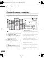
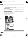
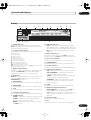
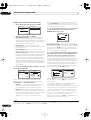
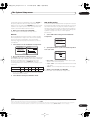
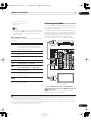
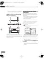
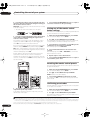
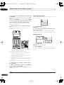
Rear panel
This illustration shows the VSX-AX4AVi, however connections for the VSX-AX2AV are the same except where noted.
20
AC IN
N
FRONT
CENTER
R
SURROUND
D
21
SURS
ROUND
D
BACK
AC OUTLET
T
TV
IN
IN2
SAT
IN
VIDEO1/
GAME1
IN
L
CENTER
R SURROUND L
R
OUT
DVR/
VCR 1
IN
OUT
DVR/
VCR 2
IN
VIDEO
DIG
IDEO
Caution
• Before making or changing the connections, switch
off the power and disconnect the power cord from the
power outlet. Plugging in should be the final step.
1 Optical digital audio output(s)
Use the OUT1 and (VSX-AX4AVi only) OUT2 jack for
recording to a CD or MiniDisc recorder.
Connecting digital audio sources on page 15.
The OUT1 jack is also used for multi-room connections.
Multi-room listening on page 54.
2 USB audio input (VSX-AX4AVi only)
Use to connect your PC as an audio source.
Using the USB interface on page 51.
3 Optical and coaxial digital audio inputs (x6)
Use for digital audio sources, including DVD players/
recorders, digital satellite receivers, CD players, etc.
See also The Input Setup menu on page 60 to assign
the inputs.
4 S-400 i.LINK connectors (x2) (VSX-AX4AVi only)
Use to connect other i.LINK audio devices for highresolution, multichannel digital audio input/output.
Using the i.LINK interface on page 48.
10
En
5 HDMI connectors (x3)
Two inputs and one output for high-quality audio/video
connection to compatible HDMI devices.
Connecting using HDMI on page 47.
6 Remote input (multi-room and source)
Use for connection to an external remote control sensor
for use in a multi-room setup, for example.
Connecting an IR receiver on page 56.
7 12V trigger jacks (total 50 mA max.) (x2)
Use to switch components in your system on and off
according to the input function of the receiver.
Switching components on and off using the 12 volt
trigger on page 57.
8 Multi-room and source outputs
Use to connect a second amplifier in a separate room.
Multi-room listening on page 54.
9 Component video connections (x4)
Use the inputs to connect any video source that has
component video output, such as a DVD recorder. Use
the output for connection to a monitor or TV.
Using the component video jacks on page 14.
10 AM and FM antenna terminals
Use to connect indoor or outdoor antennas for radio
broadcasts.
Connecting antennas on page 19.
03_connecting_up.fm 11 ページ 2005年9月20日 火曜日 午前11時50分
Connecting your equipment
11 Composite and S-video monitor outputs
Use to connect monitors and TVs.
Connecting your TV and DVD player on page 12.
12 Audio/video source inputs/(outputs) (x6)
Use for connection to audio/visual sources, such as DVD
players/recorders, VCRs, etc. Each set of inputs has jacks
for composite video, S-video1 and stereo analog audio.
03
When making cable connections
• To avoid hum, do not lay connected cables over the
top of the receiver.
Connecting a DVD/HDD recorder, VCR and other video
sources on page 13.
13 Stereo analog audio source inputs/(outputs) (x3)
Use for connection to audio sources such as CD players,
tape decks, turntables, etc.
Connecting analog audio sources on page 16.
• When connecting optical cables, be careful when
inserting the plug not to damage the shutter
protecting the optical socket.
14 Multichannel analog audio inputs
7.1 channel inputs for connection to a DVD player with
multichannel analog outputs.
Connecting the multichannel analog inputs on
page 51.
15 Control input/output
Use to connect other Pioneer components so that you
can control all your equipment from a single IR remote
sensor.
Operating other Pioneer components with this unit’s
sensor on page 72.
16 Multichannel pre-amplifier outputs
Use to connect separate amplifiers for center, surround,
surround back and subwoofer channels.
Connecting additional amplifiers on page 54 (see also
Installing your speaker system on page 17 for powered
subwoofer connection).
17 iPod input terminal
Use to connect your Apple iPod as an audio source.
Connecting an iPod on page 46.
18 RS-232C connector
Use for connection to a PC for graphical output when
using Advanced MCACC.
Connecting a PC for Advanced MCACC output on
page 59.
19 Speaker terminals
Use for connection to the main front, center, surround
and surround back speakers.
Installing your speaker system on page 17.
20 AC IN inlet
Connect the supplied power cord here.
21 Switched AC power outlet (100W/0.4A max.)
Use to power another component in the system. Power to
the outlet switches on and off with the receiver.
• When storing optical cable, coil loosely. The cable
may be damaged if bent around sharp corners.
About the video converter
The video converter ensures that all video sources are
output through all of the MONITOR VIDEO OUT jacks.
The only exception is HDMI and high-definition
component video: since these resolutions cannot be
downsampled, you must connect your monitor/TV to the
receiver’s HDMI/component video outputs when
connecting these video sources.2
If several video components are assigned to the same
input function (see The Input Setup menu on page 60),
the converter gives priority to HDMI, component, S-video,
then composite (in that order).
• For optimal video performance, THX recommends
switching Digital Video Conversion (in Setting the AV
options on page 63) OFF.
This product incorporates copyright protection technology
that is protected by U.S. patents and other intellectual
property rights. Use of this copyright protection
technology must be authorized by Macrovision
Corporation, and is intended for home and other limited
consumer uses only unless otherwise authorized by
Macrovision. Reverse engineering or disassembly is
prohibited.
AC outlet on page 20.
Note
1 You must assign the input source to the S-video input to which you’ve connected your video component (see The Input Setup menu on page 60).
2 If the video signal does not appear on your TV or plasma display, try adjusting the resolution settings on your component or display. Note that some
components (such as video game units) have resolutions that may not be converted. In this case, use an (analog) S-video or composite connection.
11
En
VSX_AX4AVi.book.fm 12 ページ 2005年6月20日 月曜日 午後6時27分
03
Connecting your equipment
component video jacks on page 14 if your TV and/or DVD
player has component video inputs/outputs. If your DVD
player offers multichannel analog audio outputs, see
Connecting the multichannel analog inputs on page 51.
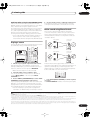
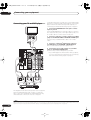
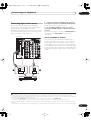
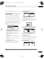
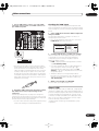
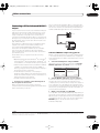
Connecting your TV and DVD player
1 Connect the MONITOR OUT video jack to a video
input on your TV.
Use a standard RCA/phono jack video cable to connect to
the composite video jack, or for higher quality video, use
an S-video cable to connect to the S-video jack.
TV
VIDEO
IN
2 Connect a composite or S-video output on your DVD
player to the DVD/LD VIDEO or DVD/LD S-VIDEO input.
Connect using a standard video cable or an S-video
cable.
S-VIDEO
IN
1
3 Connect a coaxial-type1 digital audio output on
your DVD player to the DIGITAL 1 (DVD/LD) input.
Use a coaxial cable designed for digital audio.
MULTI-ROOM
&SOURCE
/REC SEL
ANTENNA
OUT1
ROOM3(ZONE3)
FM UNBAL 75Ω
MULTI-ROOM & SOURCE
IN ROOM2(ZONE2) OUT
OUT2
S400
USB
AUDIO
IN
4 Connect the stereo audio outputs on your DVD
player to the DVD/LD AUDIO inputs.
Connect using a stereo RCA/phono jack cable.
AUDIO
PHONO
AM LOOP
MULTI-ROOM & SOURCE
MONITOR
OUT
R
ROOM2(ZONE2)
OUT
IR
L
IN
• If your DVD player has multichannel analog outputs,
you can connect these instead. See also Connecting
the multichannel analog inputs on page 51.
CD
IN
12 V TRIGGER
(AUDIO)
IN1
(SAT)
1
2
IN1
(DC OUT 12V TOTAL 50mA MAX)
ROOM2
S400
IN2
(DVR/
VCR 1)
(ZONE2)
HDMI IN1
IN1
IN3
(DVR/
VCR 2)
IN4
(CD-R)
1–4
MULTI-ROOM
& SOURCE
MONITOR
OUT
OUT
Y
Y
PB
PB
OUT
TV
IN
IN2
CD-R/
TAPE
IN1(DVD/LD)
IN2(TV)
1–2
SAT
IN
ASSIGNABLE
IN
R
FR
VIDEO1/
GAME1
IN
IN1 1–2
(DVD/
LD)
OUT
FL
SUB W.
IN2
ASSIGNABLE
IN2
(CD)
DVD/
LD
IN
PR
PR
IN2
Y
IN3
Y
PB
PB
OUT
SURROUND
DVR/
VCR 1
IN
R
OUT
DVR/
VCR 2
PR
PR
ASSIGNABLE 1–3
COMPONENT VIDEO
DIGITAL
R
SURROU
B
IN
S - VIDEO
VIDEO
VIDEO
R
AUDIO
L
OUT
M
IN
CONTROL
VSX-AX4AVi
OPTICAL
COAXIAL
DIGITAL OUT
3
S-VIDEO
VIDEO OUT
2
R
AUDIO L
ANALOG OUT
4
DVD player
The diagram shows a basic setup of this receiver together
with a TV and DVD player, with S-video or composite
video connections. Different TVs and DVD players may
offer alternative connections. See also Using the
Note
1 If your DVD player only has an optical digital output, you can connect it to one of the optical inputs on this receiver using an optical cable. When you set
up the receiver you’ll need to tell the receiver which input you connected the player to (see The Input Setup menu on page 60).
12
En
VSX_AX4AVi.book.fm 13 ページ 2005年6月20日 月曜日 午後6時27分
Connecting your equipment
03
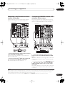
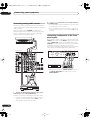
Connecting a satellite/cable receiver
or other set-top box
Connecting a DVD/HDD recorder, VCR
and other video sources
Satellite and cable receivers, and terrestrial digital TV
tuners are all examples of so-called ‘set-top boxes’.
This receiver has two sets of audio/video inputs and
outputs suitable for connecting analog or digital video
devices, including DVD/HDD recorders and VCRs.
VSX-AX4AVi
VSX-AX4AVi
MULTI-ROOM
&SOURCE
/REC SEL
ANTENNA
OUT1
ROOM3(ZONE3)
FM UNBAL 75Ω
MULTI-ROOM & SOURCE
IN ROOM2(ZONE2) OUT
OUT2
S400
USB
AUDIO
IN
AUDIO
PHONO
AM LOOP
MONITOR
OUT
MULTI-ROOM & SOURCE
R
ROOM2(ZONE2)
OUT
IR
L
MULTI-ROOM
&SOURCE
/REC SEL
IN
1
S400
IN2
(DVR/
VCR 1)
(ZONE2)
HDMI IN1
IN1
IN3
(DVR/
VCR 2)
IN4
(CD-R)
1–4
Y
DVD/
LD
IN
2
IN1
(DC OUT 12V TOTAL 50mA MAX)
ROOM2
MULTI-ROOM
& SOURCE
MONITOR
OUT
OUT
Y
TV
IN
IN2
ASSIGNABLE
PB
PB
PR
PR
FR
VIDEO1/
GAME1
IN
IN1 1–2
(DVD/
LD)
OUT
IN2
(CD)
FL
SUB W.
IN2
ASSIGNABLE
IN2
Y
OUT
SURROUND
DVR/
VCR 1
IN3
Y
DVR/
VCR 2
PR
DIGITAL
PR
ASSIGNABLE 1–3
COMPONENT VIDEO
R
S - VIDEO
R
VIDEO
VIDEO
L
AUDIO
OUT
CD
TV
IN
Y
Y
PB
PB
OUT
CD-R/
TAPE
IN1(DVD/LD)
IN2(TV)
1–2
SAT
IN
IN
R
L
FR
VIDEO1/
GAME1
IN
FL
SUB W.
PR
PR
IN2
Y
IN3
Y
PB
PB
CENTER
OUT
SURROUND
DVR/
VCR 1
IN
R
SURROUND
BACK
IN
L
IN
IN
IN2
OUT
IN2
(CD)
IN2
ASSIGNABLE
IN1 1–2
(DVD/
LD)
OUT
PB
MULTI-ROOM
& SOURCE
MONITOR
OUT
OUT
(ZONE2)
IN1
IN1
DVD/
LD
IN
2
ROOM2
ASSIGNABLE
IN
R
PB
1
HDMI IN1
IN3
(DVR/
VCR 2)
IN4
(CD-R)
1–4
CE
R
ROOM2(ZONE2)
OUT
(DC OUT 12V TOTAL 50mA MAX)
IN2
(DVR/
VCR 1)
R
MULTI-ROOM & SOURCE
12 V TRIGGER
S400
IN
AUDIO
PHONO
AM LOOP
MONITOR
OUT
IR
(AUDIO)
IN1
(SAT)
CD-R/
TAPE
SAT
IN
S400
USB
AUDIO
IN
OUT
IN1(DVD/LD)
IN2(TV)
1–2
FM UNBAL 75Ω
MULTI-ROOM & SOURCE
IN ROOM2(ZONE2) OUT
OUT2
12 V TRIGGER
(AUDIO)
IN1
(SAT)
ANTENNA
OUT1
ROOM3(ZONE3)
CD
IN
DVR/
VCR 2
PR
CONTROL
PR
ASSIGNABLE 1–3
COMPONENT VIDEO
DIGITAL
L
OUT
MULT
IN
R
SURROUND
BACK
IN
S - VIDEO
R
VIDEO
VIDEO
OUT
L
AUDIO
L
MULTI CH
IN
CONTROL
DIGITAL OUT
R
AUDIO
L
VIDEO
OPTICAL
S-VIDEO
AV OUT
COAXIAL
R
AUDIO
L
DIGITAL OUT
VIDEO
AV OUT
3
S-VIDEO
R
AUDIO
VIDEO
L
S-VIDEO
AV IN
1
2
STB
1 Connect the audio/video outputs on the set-top box
to the SAT AUDIO and VIDEO inputs.
Connect using a stereo RCA/phono jack cable and a
video or S-video1 cable.
2 Connect an optical-type2 digital audio output from
your set-top box to the DIGITAL 1 (SAT) input.3
Use an optical cable for the connection.
DVR, VCR, etc.
1 Connect the audio/video outputs of the video
player/recorder to the DVR/VCR1 AUDIO and VIDEO
inputs.
Use a stereo RCA/phono jack audio cable for the audio
connection and a video or S-video4 cable for the video
connection.
• For a second recorder, use the DVR/VCR2 IN inputs.
2 If the device can record, connect the DVR/VCR1
AUDIO and VIDEO outputs to the recorder’s audio/
video inputs.
Use a stereo RCA/phono jack audio cable for the audio
connection and a video or S-video cable for the video
connection.
Note
1 See The Input Setup menu on page 60 to assign the S-VIDEO 2 input to the SAT input function if you make this connection.
2 If your set-top box only has a coaxial digital output, you can connect it to one of the coaxial inputs on this receiver using a coaxial digital audio cable.
When you set up the receiver you’ll need to tell the receiver which input you connected the set-top box to (see The Input Setup menu on page 60).
3 If your satellite/cable receiver doesn’t have a digital audio output, you can skip this step.
4 See The Input Setup menu on page 60 to assign the S-VIDEO 2 input to the DVR/VCR1 input function if you make this connection.
13
En
VSX_AX4AVi.book.fm 14 ページ 2005年6月20日 月曜日 午後6時27分
03
Connecting your equipment
• For a second recorder, use the DVR/VCR2 outputs.
3 If the device can output digital audio, connect an
optical-type1 digital audio output from the recorder to
the DIGITAL 2 (DVR/VCR1) input.
Use an optical cable for the connection.2
• For a second recorder, use the DIGITAL 3 (DVR/
VCR2) inputs.
Using the component video jacks
Component video should give superior picture quality
when compared to composite or S-video. You can also
take advantage of progressive scan video (if your source
and TV are both compatible), which delivers a very stable,
flicker-free picture. See the manuals that came with your
TV and source component to check whether they are
compatible with progressive-scan video.
1 Connect the component video outputs of your
source to a set of ASSIGNABLE COMPONENT VIDEO
inputs.
Connect using a three-way component video cable.
• Since they are assignable, it doesn’t matter which
component video inputs you use for which source.
After connecting everything, you’ll need to assign the
component video inputs—see The Input Setup menu
on page 60.
2 Connect the COMPONENT VIDEO OUT jacks to the
component video inputs on your TV or monitor.
Use a three-way component video cable.
VSX-AX4AVi
MULTI-ROOM
&SOURCE
/REC SEL
ANTENNA
OUT1
ROOM3(ZONE3)
FM UNBAL 75Ω
MULTI-ROOM & SOURCE
IN ROOM2(ZONE2) OUT
OUT2
S400
USB
AUDIO
IN
AUDIO
PHONO
AM LOOP
MONITOR
OUT
MULTI-ROOM & SOURCE
R
ROOM2(ZONE2)
OUT
IR
L
IN
CD
IN
12 V TRIGGER
(AUDIO)
IN1
(SAT)
1
(DC OUT 12V TOTAL 50mA MAX)
ROOM2
S400
IN2
(DVR/
VCR 1)
MULTI-ROOM
& SOURCE
MONITOR
OUT
OUT
(ZONE2)
HDMI IN1
IN1
IN3
(DVR/
VCR 2)
IN4
(CD-R)
1–4
IN1
DVD/
LD
IN
IN2
TV
IN
2
OUT
CD-R/
TAPE
IN1(DVD/LD)
IN2(TV)
1–2
SAT
IN
Y
Y
PB
PB
VIDEO1/
GAME1
IN
OUT
ASSIGNABLE
IN
R
OUT
IN2
(CD)
FL
SUB W.
IN2
ASSIGNABLE
IN1 1–2
(DVD/
LD)
L
FR
PR
PR
IN2
Y
IN3
Y
PB
PB
CENTER
SURROUND
DVR/
VCR 1
IN
R
DVR/
VCR 2
PR
DIGITAL
PR
ASSIGNABLE 1–3
COMPONENT VIDEO
L
OUT
R
SURROUND
BACK
IN
S - VIDEO
VIDEO
VIDEO
R
AUDIO
L
OUT
L
MULTI CH
IN
CONTROL
Y
PB
PR
2
COMPONENT
VIDEO
TV
Y
PB
PR
1
COMPONENT
VIDEO
DVD player
Note
1 • In order to record, you must connect the analog audio cables (the digital connection is for playback only).
• If your video component doesn’t have a digital audio output, you can skip this step.
2 If your recorder only has a coaxial digital output, you can connect it to one of the coaxial inputs on this receiver using a coaxial digital audio cable. When
you set up the receiver you’ll need to tell the receiver which input you connected the recorder to (see also The Input Setup menu on page 60).
14
En
03_connecting_up.fm 15 ページ 2005年7月6日 水曜日 午後1時50分
Connecting your equipment
03
Connecting digital audio sources
This receiver has both digital inputs and outputs,
allowing you to connect digital audio components for
playback and for making digital recordings.
Most digital components also have analog connections.
See Connecting analog audio sources on the following
page if you want to connect these too.
VSX-AX4AVi
ANTENNA
FM UNBAL 75Ω
MULTI-ROOM & SOURCE
IN ROOM2(ZONE2) OUT
OUT2
S400
MULTI-ROOM & SOURCE
MONITOR
OUT
R
ROOM2(ZONE2)
OUT
IR
(AUDIO)
IN1
(SAT)
1
(ZONE2)
HDMI IN1
IN1
IN3
(DVR/
VCR 2)
IN4
(CD-R)
1–4
MULTI-ROOM
& SOURCE
MONITOR
OUT
OUT
IN2
TV
IN
CD
IN
Y
Y
PB
PB
OUT
SAT
IN
IN
R
FR
VIDEO1/
GAME1
IN
OUT
FL
SUB W.
IN2
IN1 1–2
(DVD/
LD)
PR
PR
IN2
Y
IN3
Y
PB
PB
OUT
This unit has an on-board Windows Media® Audio 9
Professional3 (WMA9 Pro) decoder, so it is possible to
playback WMA9 Pro-encoded audio using a coaxial or
optical digital connection when connected to a WMA9
Pro-compatible player. However, the connected PC, DVD
player, set-top box, etc. must be able to output WMA9 Pro
format audio signals through a coaxial or optical digital
output.
SURROUND
DVR/
VCR 1
IN
R
OUT
DVR/
VCR 2
PR
DIGITAL
OPTICAL
L
IN
CD-R/
TAPE
IN1(DVD/LD)
IN2(TV)
1–2
ASSIGNABLE
ASSIGNABLE
IN2
(CD)
IN1
DVD/
LD
IN
2
(DC OUT 12V TOTAL 50mA MAX)
ROOM2
S400
1
AUDIO
PHONO
AM LOOP
12 V TRIGGER
IN2
(DVR/
VCR 1)
2 For recording equipment, connect one of the
optical-type DIGITAL outputs to a digital input on the
recorder.
Use an optical cable to connect to the DIGITAL OUT1 or
(VSX-AX4AVi only) OUT2 (OUT1 is shown in the
illustration).2
About the WMA9 Pro decoder
MULTI-ROOM
&SOURCE
/REC SEL
OUT1
ROOM3(ZONE3)
USB
AUDIO
IN
1 Connect an optical-type1 digital audio output on
your digital component to the DIGITAL 4 (CD-R) input.
Use an optical cable for the connection.
PR
ASSIGNABLE 1–3
COMPONENT VIDEO
R
SURROU
B
IN
S - VIDEO
COAXIAL
DIGITAL OUT
VIDEO
R
VIDEO
AUDIO
OPTICAL
L
OUT
M
IN
CONTROL
2
DIGITAL IN
CD-R, MD, DAT, etc.
Note
1 • If your digital component only has a coaxial digital output, you can connect it to one of the coaxial inputs on this receiver using a coaxial cable. When
you set up the receiver you’ll need to tell the receiver which input you connected the component to (see also The Input Setup menu on page 60).
• The digital outputs from other components can be connected to any spare digital audio inputs on this receiver. You can assign them when setting up
the receiver (see also The Input Setup menu on page 60).
2 • You must switch ROOM 3 ON in Using the multi-room controls on page 56 to hear audio from the DIGITAL OUT1.
• In order to record some digital sources, you must make analog connections as explained in Connecting analog audio sources below.
3 • Microsoft, Windows Media®, and the Windows logo are trademarks, or registered trademarks of Microsoft Corporation in the United States and/or other
countries.
• With WMA9 Pro, sound problems may occur depending on your computer system. Note that WMA9 Pro 96kHz sources will be downsampled to 48kHz.
15
En
VSX_AX4AVi.book.fm 16 ページ 2005年6月20日 月曜日 午後6時27分
03
Connecting your equipment
Connecting analog audio sources
This receiver features three stereo audio-only inputs. Two
of these inputs have corresponding outputs for use with
audio recorders.
One of the audio inputs (PHONO) is a dedicated
turntable input which should not be used for any other
type of component. This input also has a grounding
terminal that most turntables require.
2
2 Turntables only: Connect the stereo audio outputs to
the PHONO inputs.
• If your turntable has a grounding wire, secure it to the
ground terminal on this receiver.
• If your turntable has line-level outputs (i.e., it has a
built-in phono pre-amp), connect it to the CD inputs
instead.
Connecting a component to the front
panel inputs
The front panel inputs comprise a composite video jack
(VIDEO), an S-Video jack (S-VIDEO), stereo analog audio
inputs (AUDIO L/R) and an optical digital audio input
(DIGITAL). You can use these connections for any kind of
audio/video component, but they are especially
convenient for portable equipment such as camcorders,
video games and portable audio/video equipment.
Turntable
VSX-AX4AVi
(TUNE +)
SPEAKERS
AV
PARAMETER
ANTENNA
FM UNBAL 75Ω
M & SOURCE
ONE2) OUT
AUDIO
PHONES
AM LOOP
MONITOR
OUT
MULTI-ROOM & SOURCE
R
ROOM2(ZONE2)
L
OUT
SIGNAL
SELECT
SBch
PROCESSING
ENTER
(ST +)
STEREO
MCACC
SETUP MIC
RETURN
DIGITAL IN
(TUNE –)
S-VIDEO
VIDEO
L AUDIO R
IN
SURROUND
IN1
DVD/
LD
IN
IN2
TV
IN
2
AL 50mA MAX)
ULTI-ROOM
& SOURCE
MONITOR
OUT
OUT
Y
SURROUND
BACK
OUT
(Single)
CD-R/
TAPE
IN1(DVD/LD)
IN2(TV)
1–2
SAT
IN
ASSIGNABLE
PB
VIDEO1/
GAME1
IN
PR
OUT
R
R
L
FR
iPod
FL
CENTER
A
R FRONT
L
CENTER
SURROUND
IN
R
L
DIGITAL OUT
OUT
PB
PR
R
SURROUND
BACK
IN
S - VIDEO
VIDEO
VIDEO
VIDEO OUTPUT
TV game, video camera, etc.
DVR/
VCR 2
E 1–3
T VIDEO
SPEAKERS
IN
DVR/
VCR 1
IN3
Y
L
IN
SUB W.
R
L
OUT
L
MULTI CH
IN
RS-232C
• Select these inputs using INPUT SELECT (remote) or
the INPUT SELECTOR dial (front panel) to select
VIDEO/GAME 2.
IN
CONTROL
AUDIO
1
OUT
PLAY
IN
REC
R
L
AUDIO IN/OUT
Tape deck, etc.
1 Connect the analog audio outputs of the source
component to one of the AUDIO inputs.
Connect using a stereo RCA/phono jack audio cable.
• If you’re connecting a tape deck, MD recorder, etc.,
connect the analog audio outputs (OUT) to the
analog audio inputs on the recorder.
16
VIDEO
SELECT
CENTER
CD
GGER
En
(ST –)
SETUP
IN
SUB W.
MULTI – ROOM &
SOURCE/REC SEL
CONTROL ON/OFF
VIDEO/GAME 2 INPUT
PRE OUT
R
L FRONT
PHONO
BAND
TUNER
EDIT
03_connecting_up.fm 17 ページ 2005年11月22日 火曜日 午後2時42分
Connecting your equipment
03
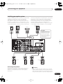
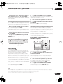
Installing your speaker system
main surround speakers should always be connected as
a pair, but you can connect just one surround back
speaker if you like (it must be connected to the left
surround back terminal). You can use speakers with a
nominal impedance between 6–16Ω (please see
Switching the speaker impedance on page 65 if you plan
to use speakers with an impedance of less than 8Ω).
To take full advantage of the receiver’s surround sound
capabilities connect front, center, surround and
surround back speakers, as well as a subwoofer.
Although this is ideal, other configurations with fewer
speakers—no subwoofer or no center speaker, or even
no surround speakers—will work. At the very least, front
left and right speakers only are necessary. Note that your
Front
right
Front
left
Subwoofer
Center
CAUTION
LINE LEVEL
INPUT
These speaker terminals carry
HAZARDOUS LIVE voltage.
To prevent the risk of electric
shock when connecting or
disconnecting the speaker
cables, disconnect the power
cord before touching any
uninsulated parts.
AC IN
MULTI-ROOM
&SOURCE
/REC SEL
ANTENNA
OUT1
ROOM3(ZONE3)
FM UNBAL 75Ω
MULTI-ROOM & SOURCE
IN ROOM2(ZONE2) OUT
OUT2
S400
USB
AUDIO
IN
AUDIO
PRE OUT
R
L FRONT
PHONO
AM LOOP
MONITOR
OUT
MULTI-ROOM & SOURCE
R
ROOM2(ZONE2)
OUT
IR
L
IN
SUB W.
CENTER
CD
IN
SURROUND
12 V TRIGGER
(AUDIO)
IN1
(SAT)
1
IN2
(DVR/
VCR 1)
(ZONE2)
HDMI IN1
IN1
IN3
(DVR/
VCR 2)
IN4
(CD-R)
1–4
DVD/
LD
IN
2
IN1
(DC OUT 12V TOTAL 50mA MAX)
ROOM2
S400
MULTI-ROOM
& SOURCE
MONITOR
OUT
OUT
Y
Y
PB
PB
TV
IN
IN2
IN1(DVD/LD)
IN2(TV)
1–2
SAT
IN
OUT
IN2
(CD)
R
R
L
FR
PR
PR
IN3
Y
PB
PB
iPod
FL
CENTER
DIGITAL
R FRONT
L
CENTER
R SURROUND L
SURROUND BACK /
R
L(Single)
B
SURROUND
DVR/
VCR 1
IN
R
PR
A
OUT
L
OUT
DVR/
VCR 2
PR
ASSIGNABLE 1–3
COMPONENT VIDEO
SPEAKERS
IN
SUB W.
IN2
Y
L
IN
VIDEO1/
GAME1
IN
IN2
IN1 1–2
(DVD/
LD)
(Single)
CD-R/
TAPE
ASSIGNABLE
ASSIGNABLE
AC OUTLET
SURROUND
BACK
OUT
R
SURROUND
BACK
IN
S - VIDEO
VIDEO
VIDEO
R
AUDIO
L
OUT
L
MULTI CH
IN
RS-232C
SELECTABLE
IN
CONTROL
VSX-AX4AVi
Surround
left
Surround
right
Surround
back left
Connecting the speakers
Each speaker connection on the receiver comprises a
positive (+) and negative (–) terminal. Make sure to
match these up with the terminals on the speakers
themselves.
Surround
back right
Caution
• Make sure that all the bare speaker wire is twisted
together and inserted fully into the speaker terminal.
If any of the bare speaker wire touches the back panel
it may cause the power to cut off as a safety measure.
17
En
VSX_AX4AVi.book.fm 18 ページ 2005年6月20日 月曜日 午後6時27分
03
Connecting your equipment
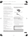
Bare wire connections
Make sure that the speaker cable you’re going to use is
properly prepared with about 10 mm of insulator stripped
from each wire, and the exposed wire strands twisted
together (fig. A).
To connect a terminal, unscrew the terminal a few turns
until there is enough space to insert the exposed wire
(fig. B). Once the wire is in position, tighten the terminal
until the wire is firmly clamped (fig. C).
fig. A
fig. B
fig. C
10mm
Important
• Please refer to the manual that came with your
speakers for details on how to connect the other end
of the speaker cables to your speakers.
• Other connections on page 46 provides greater detail
on alternate speaker setups, such as using speaker
system B (page 52), bi-amping (page 53) and biwiring (page 53).
• Place the center speaker above or below the TV so
that the sound of the center channel is localized at
the TV screen. Also, make sure the center speaker
does not cross the line formed by the leading edge of
the front left and right speakers.
• It is best to angle the speakers towards the listening
position. The angle depends on the size of the room.
Use less of an angle for bigger rooms.
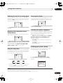
• Surround and surround back speakers should be
positioned 60 cm–90 cm higher than your ears and
titled slight downward. Make sure the speakers don't
face each other. For DVD-Audio, the speakers should
be more directly behind the listener than for home
theater playback.
• Try not to place the surround speakers farther away
from the listening position than the front and center
speakers. Doing so can weaken the surround sound
effect.
• To achieve the best possible surround sound, install
your speakers as shown below. Be sure all speakers
are installed securely to prevent accidents and
improve sound quality.
Front
left
• If you are using a THX certified subwoofer use the
THX INPUT jack on the subwoofer (if your subwoofer
has one) or switch the filter position to THX on your
subwoofer.
Placing the speakers
Subwoofer
Surround
left
Surround
right
Where you put your speakers in the room has a big effect
on the quality of the sound. The following guidelines
should help you to get the best sound from your system.
• The subwoofer can be placed on the floor. Ideally, the
other speakers should be at about ear-level when
you’re listening to them. Putting the speakers on the
floor (except the subwoofer), or mounting them very
high on a wall is not recommended.
• For the best stereo effect, place the front speakers
2–3m apart, at equal distance from the TV.
• When placing speakers near the TV, we recommend
using magnetically shielded speakers to prevent
possible interference, such as discoloration of the
picture when the TV is switched on. If you do not have
magnetically shielded speakers and notice
discoloration of the TV picture, move the speakers
farther away from the TV.
• If you're using a center speaker, place the front
speakers at a wider angle. If not, place them at a
narrower angle.
18
En
Front
right
Center
Listening position
Surround back left
Surround back right
Single surround back speaker
Caution
• Make sure that all speakers are securely installed.
This not only improves sound quality, but also
reduces the risk of damage or injury resulting from
speakers being knocked over or falling in the event of
external shocks such as earthquakes.
03_connecting_up.fm 19 ページ 2005年7月6日 水曜日 午後1時59分
Connecting your equipment
03
The diagrams below show suggested surround and
surround back speaker orientation. The first diagram (fig.
A) shows orientation with one surround back speaker (or
none) connected. The second (fig. B) shows orientation
with two surround back speakers connected.
90~120
The supplied antennas provide a simple way to listen to
AM and FM radio. If you find that reception quality is
poor, an outdoor antenna should give you better sound
quality—see Connecting external antennas below.
SR
SL
SR
SL
Connecting antennas
0~60
SR
SL
MULTI-ROOM
&SOURCE
/REC SEL
SBL
SB
SBL
SBR
ANTENNA
OUT1
ROOM3(ZONE3)
SBR
FM UNBAL 75Ω
MULTI-ROOM & SOURCE
IN ROOM2(ZONE2) OUT
OUT2
fig. A
S400
USB
AUDIO
IN
fig. B
L
C
IN2
(DVR/
VCR 1)
(ZONE2)
HDMI IN1
IN1
IN3
(DVR/
VCR 2)
IN4
(CD-R)
1–4
Y
MULTI-ROOM
& SOURCE
MONITOR
OUT
OUT
IN2
TV
IN
SUB W.
CENTER
CD
IN
Y
OUT
(Single)
CD-R/
TAPE
IN1(DVD/LD)
IN2(TV)
1–2
SAT
IN
PB
PB
VIDEO1/
GAME1
IN
PR
PR
OUT
R
R
L
FR
IN3
Y
PB
OUT
PR
PR
IN
CENTER
R FRONT
L
C
IN
R
DIGITAL
A
SURROUND
DVR/
VCR 2
ASSIGNABLE 1–3
COMPONENT VIDEO
SPEAKERS
IN
DVR/
VCR 1
PB
iPod
FL
SUB W.
IN2
Y
L
IN
IN2
ASSIGNABLE
SURROUND
BACK
OUT
ASSIGNABLE
S - VIDEO
VIDEO
VIDEO
R
R
AUDIO
L
L
SURROUND
BACK
OUT
L
MULTI CH
IN
RS-232C
IN
CONTROL
VSX-AX4AVi
AM loop antenna
1
Assemble the stand as shown in the illustration.
fig. A
SL
L
SURROUND
IN1
DVD/
LD
IN
2
(DC OUT 12V TOTAL 50mA MAX)
IN2
(CD)
R
1
ROOM2
IN1 1–2
(DVD/
LD)
If you have a complete THX speaker system, follow the
diagram below to place your speakers. Note that the
surround speakers ( indicates bi-polar radiating
speakers) should output at an angle parallel to the
listener.
PRE OUT
R
L FRONT
IN
12 V TRIGGER
S400
THX speaker system setup
R
ROOM2(ZONE2)
OUT
IR
(AUDIO)
IN1
(SAT)
• If you have two surround back speakers THX
recommends placing them together and the same
distance from your listening position (see below).
AUDIO
PHONO
AM LOOP
MULTI-ROOM & SOURCE
MONITOR
OUT
fig. B
fig. C
SR
Surround
Surround
• Bend the stand in the direction indicated (fig. A).
SBL
• Clip the loop into the stand (fig. B).
SBR
Surround back
• If you have two surround back speakers THX
recommends placing them together and the same
distance from your listening position for the following
THX modes: THX Select2 CINEMA, THX
MUSICMODE and THX GAMES MODE.
See also THX Audio Setting on page 45 to make the
settings that will give you the best sound experience
when using the Home THX modes (on page 27).
• It’s possible to fix the AM antenna to a wall (fig. C).
Before fixing, make sure that the reception is
satisfactory.
2 Pull off the protective shields of both AM antenna
wires.
3 Press the AM LOOP antenna terminal tabs to open
and insert one wire into each terminal.
4
Release the tabs to secure the AM antenna wires.
5 Place the AM antenna on a flat surface and point in
the direction giving the best reception.
Avoid placing near computers, television sets or other
electrical appliances and do not let it come into contact
with metal objects.
19
En
VSX_AX4AVi.book.fm 20 ページ 2005年6月20日 月曜日 午後6時27分
03
Connecting your equipment
Important
• The signal ground () is designed to reduce noise
that occurs when an antenna is connected. It is not
an electrical safety ground.
Plugging in the receiver
Only plug in after you have connected all your
components to this receiver, including the speakers.
Caution
FM wire antenna
• Handle the power cord by the plug part. Do not pull
out the plug by tugging the cord, and never touch the
power cord when your hands are wet, as this could
cause a short circuit or electric shock. Do not place
the unit, a piece of furniture, or other object on the
power cord or pinch the cord in any other way. Never
make a knot in the cord or tie it with other cables. The
power cords should be routed so that they are not
likely to be stepped on. A damaged power cord can
cause a fire or give you an electric shock. Check the
power cord once in a while. If you find it damaged,
ask your nearest Pioneer authorized independent
service company for a replacement.
• Connect the FM wire antenna to the FM UNBAL
75Ω in the same way as the AM antenna.
For best results, extend the FM antenna fully and fix to a
wall or door frame. Don’t drape loosely or leave coiled up.
Connecting external antennas
To improve FM reception connect an external FM
antenna to the FM UNBAL 75Ω.
• Do not use any power cord other than the one
supplied with this unit.
75Ω coaxial cable
• Do not use the supplied power cord for any purpose
other than that described below.
• The receiver should be disconnected by removing the
mains plug from the wall socket when not in regular
use, e.g., when on vacation.
ANTENNA
• Make sure the blue STANDBY/ON light has gone
out before unplugging.
To improve AM reception, connect a 5–6m length of vinylcoated wire to the AM LOOP terminals without
disconnecting the supplied AM loop antenna.
1 Plug the supplied power cord into the AC IN
socket on the back of the receiver.
For the best possible reception, suspend horizontally
outdoors.
2
Outdoor antenna
Plug the other end into a power outlet.
AC outlet
Indoor antenna
(vinyl-coated wire)
Power supplied through this outlet is turned on and off by
the receiver's power switch. Total electrical power
consumption of connected equipment should not exceed
100 W (0.4 A).
5–6 meters
Caution
• Do not connect a TV set, monitor, heater, or similar
appliance to this unit's AC outlet.
• Do not connect appliances with high power
consumption to the AC outlet in order to avoid
overheating and fire risk. This can also cause the
receiver to malfunction.
• Since a subwoofer or power amplifier can exceed the
100W maximum when playing sources at a high
volume, this type of equipment should not be
connected to the AC outlet.
20
En
VSX_AX4AVi.book.fm 21 ページ 2005年6月20日 月曜日 午後6時27分
Controls and displays
04
Chapter 4:
Controls and displays
Front panel
Illustration shows the VSX-AX4AVi front panel
1
2
3
4 5
6 7
8
9
10
11
AUDIO/VIDEO MULTI-CHANNEL RECEIVER
12
VSX-AX4AVi
STANDBY/ON
PHASE
CONTROL
DIGITAL PRECISION
PROCESSING
PHASE
CONTROL
MCACC
POSITION
AUTO SURR/
STREAM DIRECT
HOME
THX
STANDARD
SURROUND
INPUT
SELECTOR
13
ADVANCED
SURROUND
MASTER
VOLUME
14
15
16
(TUNE +)
SPEAKERS
17
BAND
AV
PARAMETER
18
MULTI – ROOM &
SOURCE/REC SEL
CONTROL ON/OFF
19
VIDEO
SELECT
20
SIGNAL
SELECT
21
SBch
PROCESSING
22
STEREO
TUNER
EDIT
VIDEO/GAME 2 INPUT
PHONES
(ST –)
(ST +)
ENTER
MCACC
SETUP MIC
RETURN
SETUP
DIGITAL IN
(TUNE –)
23
24
25
26
1 INPUT SELECTOR dial
Use to select an input source.
2 STANDBY/ON
Switches the receiver between on and standby. Power
indicator lights when the receiver is on.
3
PHASE CONTROL – Press to switch on/off phase
correction (page 9).
MCACC POSITION – Press to switch between
MCACC presets (page 28).
AUTO SURR / STREAM DIRECT – Press to select
Auto Surround (page 26) or Stream Direct (page 28)
listening.
S-VIDEO
VIDEO
27
L AUDIO R
28
5 Remote sensor
Receives the signals from the remote control (see
Operating range of remote control unit on page 22).
6 MCACC indicator
Lights when one of the MCACC presets (page 28) is
selected.
7 Digital Precision Processing indicator
Lights to indicate digital processing (for example, it
disappears when Pure Direct (page 28) is on, or when
listening through the multichannel analog inputs).
8 Character display
See Display on page 23.
4 PHASE CONTROL indicator
Lights when Phase Control is switched on (page 9).
21
En
VSX_AX4AVi.book.fm 22 ページ 2005年6月20日 月曜日 午後6時27分
04
Controls and displays
9 HDMI indicator
Blinks when connecting an HDMI-equipped component;
lights when the component is connected (page 47).
10 i.LINK indicator (VSX-AX4AVi only)
Lights when an i.LINK-Audio-equipped component is
selected (page 48).
DIGITAL VIDEO CONVERSION indicator (VSX-AX2AV
only)
Lights when digital video conversion is enabled
(page 63).
11 Listening mode buttons
HOME THX – Press to select a Home THX listening
mode (page 27).
STANDARD SURROUND – Press for Standard
decoding and to switch between the various 2Pro
Logic IIx and Neo:6 options (page 26).
ADVANCED SURROUND – Use to switch between
the various surround modes (page 27).
20 SIGNAL SELECT
Use to select an input signal (page 28).
21 SBch PROCESSING
Selects the surround back channel mode (page 29) or
virtual surround back mode (page 29).
22 STEREO
Switches to stereo playback (page 28).
23 PHONES jack
Use to connect headphones. When the headphones are
connected, there is no sound output from the speakers.
24 SETUP
Press to access the System Setup menu (see page 33).
25 (TUNE/ST +/–) /ENTER
Use the arrow buttons when setting up your surround
sound system (see page 33). Use the TUNE +/– buttons
to find radio frequencies and use ST +/– to find preset
stations (page 30).
12 MASTER VOLUME dial
26 RETURN
Press to confirm and exit the current menu screen.
13 Front panel controls
To access the front panel controls, push gently on the
lower third portion of the panel with your finger.
27 MCACC SETUP MIC jack
Use to connect the supplied microphone.
STA
NDB
Y/ON
28 VIDEO/GAME 2 INPUT
See Connecting a component to the front panel inputs on
page 16.
Operating range of remote control unit
The remote control may not work properly if:
• There are obstacles between the remote control and
the receiver's remote sensor.
14 SPEAKERS
Use to change the speaker system (page 52).
15 AV PARAMETER
Use to access the AV options (page 63).
16 TUNER EDIT
Use with / to memorize and name stations for recall
(page 30).
• Direct sunlight or fluorescent light is shining onto the
remote sensor.
• The receiver is located near a device that is emitting
infrared rays.
• The receiver is operated simultaneously with another
infrared remote control unit.
17 BAND
Switches between AM and FM radio bands (page 30).
18 MULTI ROOM & SOURCE / REC SEL controls
If you’ve made multi-room connections (see Multi-room
listening on page 54) use these controls to control the
sub room from the main room (see Using the multi-room
controls on page 56).
You will also need to use the REC SEL controls when
recording a source (see Making an audio or a video
recording on page 64).
19 VIDEO SELECT
Press repeatedly to select the video source (page 65).
22
En
STAN
DBY
/ON
30
30
AUD
IO/V
IDEO
MUL
TI-CH
ANN
EL
REC
EIVE
R
7m
VSX_AX4AVi.book.fm 23 ページ 2005年6月20日 月曜日 午後6時27分
Controls and displays
04
Display
1
2
3
SIGNAL
L
C
R 2DIGITAL
WMA9 Pro
SL S SR
DSD
HDMI
SBL SB SBR
DIGITAL
CD
LFE
ANALOG
CD-R
STREAM DIRECT
Neo : 6
2PRO LOGIC
THX ADV.SURROUND
STEREO STANDARD
SLEEP
SP AB
AUTO
13
14
15
16
4 5
6
7
8
9
10
11
DTS VIDEO CONV. V.SB DNR MIDNIGHT TUNED RDS
96/24 MULTI-ROOM DIALOGUE LOUDNESS STEREO EON
PCM OVER ATT Hi-bit/sampling TONE MONO
TUNER
PHONO
MULTI IN DVD
iPod
TV
17
SAT
DVR
VIDEO HDMI
[1]
[2]
12
dB
USB
18
SR+
19
1 SIGNAL indicators
Light to indicate the currently selected input signal.
AUTO lights when the receiver is set to select the input
signal automatically (page 28).
10 EON / RDS indicators
EON – Lights when the EON mode is set (flashes
during EON reception). The
indicator lights when
the current station carries the EON service (page 32).
2 Program format indicators
These change according to which channels are active in
digital sources.
RDS – Lights when an RDS broadcast is received
(page 31).
L – Left front channel
C – Center channel
R – Right front channel
SL – Left surround channel
S – Surround channel (mono)
SR – Right surround channel
SBL – Left surround back channel
SB – Surround back channel (mono)
SBR – Right surround back channel
LFE – Low frequency effects channel (the ((( ))) indicators light when
an LFE signal is being input)
3 Digital format indicators
Light when a signal encoded in the corresponding format
is detected (DSDPCM lights during DSD (Digital
Stream Direct) to PCM conversion with SACDs).
4 OVER / ATT
OVER lights to indicate that the level of an analog source
is too high. ATT lights when you use the attenuator
(ANALOG ATT) to reduce it.
5 MULTI-ROOM
Lights when the multi-room feature is active (page 54).
6 VIDEO CONV.
Lights when digital video conversion is enabled (page 63).
7 V.SB
Lights during Virtual surround back processing (page 29).
8 Sound processing indicators
Light according to the active AV parameter(s) (page 63).
9
TUNER indicators
TUNED – Lights when a broadcast is being received.
STEREO – Lights when a stereo FM broadcast is
being received in auto stereo mode.
MONO – Lights when the mono mode is set using
the MPX button.
11 Master volume level
Shows the overall volume level. –80dB indicates the
minimum level, and +12dB indicates the maximum level.
12 Input source indicators
Light to indicate the input source you have selected.
13 STREAM DIRECT
Lights when Direct / Pure Direct is selected (page 28).
14 Speaker indicators
Indicate the current speaker system, A and/or B (page 52).
15 Listening mode indicators
THX – Lights when a Home THX mode is selected.
ADV. SURROUND – Lights when an Advanced
Surround mode has been selected.
STEREO – Lights when stereo listening is switched
on (see Listening in stereo on page 28).
STANDARD – Lights when a Standard Surround
mode is switched on (see Listening in surround
sound on page 26).
16 SLEEP
Lights when the receiver is in sleep mode (page 65).
17 Matrix decoding format indicators
2PRO LOGIC IIx – This lights to indicate 2Pro
Logic II / 2Pro Logic IIx decoding (page 26).
Neo:6 – When one of the Neo:6 modes of the receiver
is on, this lights to indicate Neo:6 processing
(page 26).
18 Character display
Displays various system information.
19 SR+
Lights when the SR+ mode is switched on (page 58).
23
En
04_controls_displays.fm 24 ページ 2005年7月6日 水曜日 午後2時2分
04
Controls and displays
3 Input source buttons
Press to select control of other components (see
Controlling the rest of your system on page 67).
Remote control
12
4 Number buttons and other receiver/component
controls
Use the number buttons to directly select a radio
frequency (page 30) or the tracks on a CD, DVD, etc.
13
DISC (ENTER) can be used to enter commands for TV or
DTV, and also to select a disc in a multi-CD player.
SYSTEM OFF
INPUT
SELECT
RECEIVER
1
2
3
SOURCE
Press RECEIVER first to access:
CD
TV
VIDEO 2
DVD
SAT
VIDEO 1
DVR2
CD-R
MULTI IN
ROOM2/3
DVR1
i Pod
TUNER
RECEIVER
SLEEP
TV CONT
VIDEO
SEL
SR+
14
VIDEO SEL – Press repeatedly to select the video
source (page 65).
ANALOG
ATT
DIMMER
ANALOG ATT – Attenuates (lowers) the level of an
analog input signal to prevent distortion (page 65).
4
D.ACCESS
+10
CLASS
DISC
SR+ – Switches the SR+ mode on/off (page 58).
ENTER
5
AV PARAMETER
TOP MENU CH LEVEL
MENU
DIMMER – Dims or brightens the display (page 65).
TUNE
ST
6
ST
ENTER
SETUP
GUIDE
PTY SEARCH
Press TUNER first to access:
T.EDIT
RETURN
TUNE
D.ACCESS – After pressing, you can access a radio
station directly using the number buttons (page 30).
BAND
TV CONTROL
7
INPUT
SELECT
TV VOL
15
VOL
TV CH
REC
MUTE
A
MPX
8
16
REC STOP
EON
B
C
AUDIO SUBTITLE
DISP
9
10
11
SLEEP – Use to put the receiver in sleep mode and
select the amount of time before sleep (page 65).
D
HDD
CH
STATUS SIGNAL SEL
MULTI OPE
THX
SHIFT
PHASE
SBch
E
DVD
CH
STEREO
STANDARD ADV. SURR
MCACC
S.DIRECT
17
18
CLASS – Switches between the three banks (classes)
of radio station presets (page 30).
5 Tuner/component control buttons/SETUP
These button controls can be accessed after you have
selected the corresponding input source button (DVD,
DVR1, TV, SAT etc.). The BAND, T.EDIT and PTY
SEARCH tuner controls are explained from page 30.
Press RECEIVER first to access the following controls:
AV PARAMETER – Use to access the AV options
(page 63).
SETUP – Use to access the System Setup menu
(page 33).
RECEIVER
The remote has been conveniently color-coded according
to component control using the following system (press
the corresponding input source button to access):
• Green – Receiver controls (see below)
• Red – DVD controls (page 71)
• Blue – Tuner controls (page 30)
• Yellow – iPod controls (page 46)
• White – Other controls (page 71)
1 RECEIVER
This switches between standby and on for this receiver.
2 INPUT SELECT
Use to select the input source (use SHIFT for INPUT
SELECT
).
24
En
CH LEVEL – Press repeatedly to select a channel,
then use / to adjust the level (page 44).
RETURN – Press to confirm and exit the current
menu screen (also use to return to the previous menu
with DVDs or to select closed captioning with DTV).
6 (TUNE/ST) /ENTER
Use the arrow buttons when setting up your surround
sound system (see page 33) and the AV options
(page 63). Also used to control DVD menus/options and
for deck 1 of a double cassette deck player. Use the TUNE
/ buttons to find radio frequencies and use ST /
to find preset stations (page 30).
7 TV CONTROL buttons
These buttons are dedicated to control the TV assigned to
the TV CONT button. Thus if you only have one TV to hook
up to this system assign it to the TV CONT input source
button. If you have two TVs, assign the main TV to the TV
CONT button (see page 67 for more on this).
VSX_AX4AVi.book.fm 25 ページ 2005年6月20日 月曜日 午後6時27分
Controls and displays
TV – Use to turn on/off the power of the TV.
TV VOL +/– – Use to adjust the volume on your TV.
INPUT SELECT – Use to select the TV input signal.
TV CH +/– – Use to select channels.
8 Component control buttons
The main buttons (, , etc.) are used to control a
component after you have selected it using the input
source buttons.
The controls above these buttons can be accessed after
you have selected the corresponding input source button
(for example DVD, DVR1, TV or SAT). The following
controls can be accessed when listening to the built-in
tuner:
MPX – Switches between stereo and mono reception
of FM broadcasts. If the signal is weak then switching
to mono will improve the sound quality (page 30).
DISP – Switches between named station presets and
radio frequencies (page 31).
EON – Use to search for programs that are
broadcasting traffic or news information (page 32).
9 STATUS
Press to check selected receiver settings (page 65).
10 MULTIOPE
Use this button to perform multi operations (page 69).
11 SHIFT
Press to access the controls outlined in white boxes (for
example, INPUT SELECT
), or to display the currently
selected input source in the remote control LCD.
12 SOURCE
Press to turn on/off other components connected to the
receiver (see page 67 for more on this).
13 Character display (LCD)
This display shows information when transmitting
control signals.
The following commands are shown when you’re setting
the remote to control other components (see Controlling
the rest of your system on page 67):
04
ERASE – See Erasing one of the remote control button
settings on page 68.
RESET – See Resetting the remote control presets on
page 68.
READ ID – See Confirming preset codes on page 68.
14 RECEIVER
Switches the remote to control the receiver (used to
select the green commands above the number buttons
(ANALOG ATT, etc). Also use this button to set up
surround sound (page 7, page 33). With SHIFT, this
selects the multi-room control (page 54), shown in the
display as RCV/RM2, RCV/RM3.
15 VOL +/–
Use to set the listening volume.
16 MUTE
Mutes the sound or restores the sound if it has been
muted (adjusting the volume also restores the sound).
17 Receiver controls
SIGNAL SEL – Use to select an input signal (page 28).
SBch – Use to select the surround/virtual back
channel mode (page 29).
STEREO – Switches between direct and stereo
playback. Direct playback bypasses the tone controls
and any other signal processing for the most
accurate reproduction of a source (page 28).
THX – Press to select a Home THX listening mode
(page 27).
STANDARD – Press for Standard decoding and to
switch between the various Pro Logic IIx and Neo:6
options (page 26).
ADV.SURR – Use to switch between the various
surround modes (page 27).
18 PHASE – Press to switch on/off phase correction
(page 9).
MCACC – Press to switch between MCACC presets
(page 28).
S.DIRECT – Press to select Auto Surround (page 26)
or Stream Direct (page 28) listening.
SETUP – Indicates the setup mode, from which you
choose the options below.
PRESET – See Selecting preset codes directly on
page 67.
LEARNING – See Programming signals from other
remote controls on page 67.
MULTI OP – See Multi Operation and System Off on
page 69.
SYS OFF – See Multi Operation and System Off on
page 69.
DIRECT F – See Direct function on page 69.
RENAME – See Renaming input source names on
page 69.
25
En
VSX_AX4AVi.book.fm 26 ページ 2005年6月20日 月曜日 午後6時27分
05
Listening to your system
Chapter 5:
Listening to your system
Important
• The listening modes and many features described in
this section may not be available depending on the
current source, settings and status of the receiver.
See Listening modes with different input signal
formats on page 82 for more on this.
• While listening to a source, press STANDARD
(STANDARD SURROUND).
If necessary, press repeatedly to select a listening mode.
• If the source is Dolby Digital, DTS, or Dolby Surround
encoded, the proper decoding format will
automatically be selected and shows in the display.4
With two channel sources, you can select from:
• 2 Pro Logic IIx MOVIE – Up to 7.1 channel sound,
especially suited to movie sources
Auto playback
There are many ways to listen back to sources using this
receiver, but for the simplest, most direct listening option
is the Auto Surround feature. The receiver automatically
detects what kind of source you’re playing and selects
multichannel or stereo playback as necessary.1
STATUS SIGNAL SEL
MULTI OPE
THX
SHIFT
PHASE
SBch
STEREO
• 2 Pro Logic IIx MUSIC – Up to 7.1 channel sound,
especially suited to music sources5
• 2 Pro Logic IIx GAME– Up to 7.1 channel sound,
especially suited to video games
• 2 PRO LOGIC – 4.1 channel surround sound (sound
from the surround speakers is mono)
STANDARD ADV. SURR
MCACC
S.DIRECT
• While listening to a source, press S.DIRECT (AUTO
SURR/STREAM DIRECT)2 for auto playback of a source.
AUTO SURROUND shows briefly in the display before
showing the decoding or playback format. Check the
digital format indicators in the front panel display to see
how the source is being processed.
Listening in surround sound
Using this receiver, you can listen to any source in
surround sound. However, the options available will
depend on your speaker setup and the type of source
you’re listening to.
If you connected surround back speakers, see also Using
surround back channel processing on page 29.
Standard surround sound
• Neo:6 CINEMA – 6.1 channel sound, especially
suited to movie sources
• Neo:6 MUSIC – 6.1 channel sound, especially suited
to music sources6
With multichannel sources, if you have connected
surround back speaker(s) and have selected SBch ON, you
can select (according to format):
• 2 Pro Logic IIx MOVIE – See above (only available
when you’re using two surround back speakers)
• 2 Pro Logic IIx MUSIC – See above
• Dolby Digital EX – Creates surround back channel
sound for 5.1 channel sources and provides pure
decoding for 6.1 channel sources (like Dolby Digital
Surround EX)
• DTS-ES – Allows you to hear 6.1 channel playback
with DTS-ES encoded sources
• DTS Neo:6 – Allows you to hear 6.1 channel playback
with DTS encoded sources
The following modes provide basic surround sound for
stereo and multichannel sources.3
STATUS SIGNAL SEL
MULTI OPE
THX
SHIFT
PHASE
SBch
STEREO
STANDARD ADV. SURR
MCACC
S.DIRECT
Note
1 • Stereo surround (matrix) formats are decoded accordingly using Neo:6 CINEMA or 2 Pro Logic IIx MOVIE (see Listening in surround sound above
for more on these decoding formats).
• The Auto Surround feature is canceled if you connect headphones or select the multichannel analog inputs.
2 For more options using this button, see Using Stream Direct on page 28.
3 In modes that give 6.1 channel sound, the same signal is heard from both surround back speakers.
4 If surround back channel processing (page 29) is switched OFF, or the surround back speakers are set to NO (this happens automatically if the Surround
back speaker setting on page 35 is set to anything but Normal (SB)), 2 Pro Logic IIx becomes 2 Pro Logic II (5.1 channel sound).
5 When listening to 2-channel sources in Dolby Pro Logic IIx Music mode, there are three further parameters you can adjust: Center Width, Dimension,
and Panorama. See Setting the AV options on page 63 to adjust them.
6 When listening to 2-channel sources in Neo:6 Music mode, you can also adjust the center image effect (see Setting the AV options on page 63).
26
En
VSX_AX4AVi.book.fm 27 ページ 2005年6月20日 月曜日 午後6時27分
Listening to your system
05
Using the Home THX modes
Using the Advanced surround effects
THX and Home THX are technical standards created by
Lucasfilm Ltd. for cinema and home theater sound.
Home THX is designed to make home theater audio
sound more like what you hear in a cinema.
The Advanced surround effects can be used for a variety
of additional surround sound effects. Most Advanced
Surround modes are designed to be used with film
soundtracks, but some modes are also suited for music
sources. Try different settings with various soundtracks
to see which you like.
Different THX options will be available depending on the
source and the setting for surround back channel
processing (see Using surround back channel processing
on page 29 for more on this).
STATUS SIGNAL SEL
MULTI OPE
THX
SHIFT
PHASE
SBch
STATUS SIGNAL SEL
STEREO
MULTI OPE
THX
SHIFT
PHASE
SBch
STEREO
STANDARD ADV. SURR
MCACC
S.DIRECT
STANDARD ADV. SURR
MCACC
S.DIRECT
• Press THX (HOME THX) to select a listening mode.1
With two channel sources, press THX (HOME THX)
repeatedly to select a matrix-decoding process for the
THX CINEMA mode (see Listening in surround sound
above for an explanation of each process):
• 2 Pro Logic IIx MOVIE+THX
• 2 PRO LOGIC+THX
• Neo:6 CINEMA+THX
• THX GAMES MODE
With multichannel sources, press THX (HOME THX)
repeatedly to select from:
• THX CINEMA – Gives you cinema-quality sound from
your home theatre system using all the speakers in
your setup
• 2 Pro Logic IIx MOVIE+THX – Especially suited to
movie sources, this allows you to hear 7.1 channel
playback with 5.1 channel sources
• THX Surround EX – Allows you to hear 6.1 or 7.1
channel playback with 5.1 channel sources
• THX Select2 CINEMA – Allows you to hear 7.1
channel playback with 5.1 channel sources
• THX MUSICMODE – Allows you to hear 7.1 channel
playback with 5.1 channel sources
• THX GAMES MODE – Allows you to hear 7.1 channel
playback from the output of a video game console
• Press ADV.SURR (ADVANCED SURROUND)
repeatedly to select a listening mode.2
• ACTION – Designed for action movies with dynamic
soundtracks
• SCI-FI – Designed for science fiction with lots of
special effects
• DRAMA – Designed for movies with lots of dialog
• MUSICAL – Creates a concert hall-type sound for
musicals
• MONOFILM – Creates surround sound from mono
soundtracks
• 7-D THEATER – Creates an extra wide stereo field
• CLASSICAL – Gives a large concert hall-type sound
• CHAMBER – Creates a space with alot of reverb
• JAZZ – Creates the sound of a small jazz club
• ROCK – Creates a live concert sound for rock music
• DANCE – Designed for music with lots of bass
• 7ch STEREO – Allows you to hear stereo sources
from all the speakers in your setup
• PhonesSurround – When listening through
headphones, you can still get the effect of overall
surround.
Tip
• When an Advanced Surround listening mode is
selected, the effect level can be adjusted using the
EFFECT parameter in Setting the AV options on
page 63.
Note
1 • If you only have one surround back speaker connected, 2 Pro Logic IIx MOVIE+THX, THX Select2 CINEMA, THX MUSICMODE and THX GAMES
MODE are not available.
• You can’t use the THX modes when headphones are connected.
2 • Depending on the source and the sound mode you have selected, you may not get sound from the surround back speakers in your setup. For more on
this, refer to Using surround back channel processing on page 29.
• If you press ADV. SURR when the headphones are connected, the PhonesSurround mode will automatically be selected.
27
En
VSX_AX4AVi.book.fm 28 ページ 2005年6月20日 月曜日 午後6時27分
05
Listening to your system
Listening in stereo
Selecting MCACC presets
When you select STEREO, you will hear the source
through just the front left and right speakers (and
possibly your subwoofer depending on your speaker
settings). Dolby Digital and DTS multichannel sources
are downmixed to stereo.
STATUS SIGNAL SEL
MULTI OPE
THX
SHIFT
PHASE
SBch
STEREO
• Default setting: MEMORY 1
If you have calibrated your system for different listening
positions2, you can switch between settings to suit the
kind of source you’re listening to and where you’re sitting
(for example, watching movies from a sofa, or playing a
video game close to the TV).
STANDARD ADV. SURR
STATUS SIGNAL SEL
MCACC
• While listening to a source, press STEREO for stereo
playback.
Using Stream Direct
Use the Stream Direct modes when you want to hear the
truest possible reproduction of a source. All unnecessary
signal processing is bypassed, and you’re left with the
pure analog or digital sound source (see Stream direct
with different input signal formats on page 84).
STATUS SIGNAL SEL
MULTI OPE
THX
SHIFT
PHASE
SBch
STEREO
STANDARD ADV. SURR
MCACC
SBch
STEREO
S.DIRECT
MULTI OPE
THX
SHIFT
PHASE
STANDARD ADV. SURR
MCACC
S.DIRECT
• While listening to a source, press MCACC (MCACC
POSITION).
Press repeatedly to select one of the six MCACC presets3
or to switch calibration off. See Data Management on
page 41 to check and manage your current settings.
Choosing the input signal
You need to hook up a component to both analog and
digital inputs on the receiver to select between input
signals.4
S.DIRECT
STATUS SIGNAL SEL
1 While listening to a source, press S.DIRECT
(AUTO SURR/STREAM DIRECT) to select the mode
you want.
Check the digital format indicators in the front panel
display to see how the source is being processed.
• AUTO SURROUND – See Auto playback on page 26.
• DIRECT – Sources are heard according to the
settings made in the Surround Setup (speaker
setting, channel level, speaker distance, acoustic
calibration EQ, and X-curve), as well as with dual
mono, the input attenuator, and any sound delay and
hi-bit/hi-sampling settings. You will hear sources
according to the number of channels in the signal.
• PURE DIRECT – Analog and PCM sources are heard
without any digital processing.1 No sound is output
from the Second Zone in this mode.
MULTI OPE
THX
SHIFT
PHASE
SBch
STEREO
STANDARD ADV. SURR
MCACC
S.DIRECT
• Press SIGNAL SEL (SIGNAL SELECT) to select the
input signal corresponding to the source component.
Each press cycles through the options as follows:
• AUTO – This is the default setting. The receiver
selects the first available signal in the following
order: ; HDMI; DIGITAL; ANALOG.
• ANALOG – Selects an analog signal.
• DIGITAL – Selects an optical or coaxial digital signal.
• HDMI – Selects an HDMI signal.5
•
– Selects an i.LINK signal (VSX-AX4AVi only).
Note
1 There are cases where a brief noise is heard before playback of sources other than PCM. Please select AUTO SURROUND or DIRECT if this is a problem.
2 Different presets might also have separate calibration settings for the same listening position, depending on how you’re using your system. These presets can be set in Automatically setting up for surround sound (MCACC) on page 7 or Automatic MCACC (Expert) on page 33, either of which you should
have already completed.
3 You can’t use these settings when MULTI CH IN is switched on, and they has no effect when headphones are connected.
4 • This receiver can only play back Dolby Digital, PCM (32kHz–96 kHz), DTS (including DTS 96kHz/24 bit) and WMA9 Pro digital signal formats. With other
digital signal formats, set to ANALOG (the MULTI CH IN, TUNER, PHONO and iPod input functions are all fixed to ANALOG).
• You may get digital noise when a LD or CD player compatible with DTS is playing an analog signal. To prevent noise, make the proper digital connections (page 15) and set the signal input to DIGITAL.
• Some DVD players don’t output DTS signals. For more details, refer to the instruction manual supplied with your DVD player.
• Even when i.LINK is selected and the i.LINK indicator lights, you won’t hear any sound if the output settings of your i.LINK device are off.
• The input signal for unassigned i.LINK-equipped components is fixed to . See Checking the i.LINK inputs on page 49.
5 When the HDMI option in Setting the AV options on page 63 is set to THROUGH, the sound will be heard through your TV, not from this receiver.
28
En
VSX_AX4AVi.book.fm 29 ページ 2005年6月20日 月曜日 午後6時27分
Listening to your system
05
• PCM – Only PCM signals are output.1 The receiver
selects the first available signal in the following
order: ; HDMI; DIGITAL.
When set to DIGITAL or AUTO, 2 DIGITAL lights with
Dolby Digital decoding, DTS lights with DTS decoding,
and WMA9 Pro lights to indicate decoding of a WMA9
Pro signal.
• SBch ON – 6.1 or 7.1 decoding is always used (for
example, a surround back channel will be generated
for 5.1 encoded material)
• SBch AUTO – Automatically switches to 6.1 or 7.1
decoding for 6.1 encoded sources (for example,
Dolby Digital EX or DTS-ES)
• SBch OFF – Maximum 5.1 playback
Using the Virtual Surround Back mode
Using surround back channel processing
• Default setting: SBch ON
You can have the receiver automatically use 6.1 or 7.1
decoding for 6.1 encoded sources (for example, Dolby
Digital EX or DTS-ES), or you can choose to always use
6.1 or 7.1 decoding (for example, with 5.1 encoded
material). With 5.1 encoded sources, a surround back
channel will be generated, but the material may sound
better in the 5.1 format for which it was originally
encoded (in which case, you can simply switch surround
back channel processing off).
MULTI OPE
THX
SHIFT
PHASE
SBch
• VirtualSB ON – Virtual Surround Back is always used
(for example, on 5.1 encoded material)
STEREO
• VirtualSB AUTO – Virtual Surround Back is
automatically applied to 6.1 encoded sources (for
example, Dolby Digital EX or DTS-ES)
STANDARD ADV. SURR
MCACC
S.DIRECT
• Press SBch (SBch PROCESSING) repeatedly to cycle
the surround back channel options.
Each press cycles through the options as follows:
Type of source
Dolby Digital EX/DTS-ES encoded
multichannel sources with 6.1ch surround
Dolby Digital/DTS/WMA9 Pro encoded, DVDAudio and SACD multichannel sources
The table indicates when you will hear the virtual
surround back channel. (=Virtual surround back
channel is active)
• Press SBch (SBch PROCESSING) repeatedly to cycle
the virtual surround back channel options.
Each press cycles through the options as follows:
The table below indicates when you will hear the
surround back channel when playing various kinds of
sources. (=Sound plays through surround back
speaker(s))
STATUS SIGNAL SEL
When you’re not using surround back speakers,
selecting this mode allows you to hear a virtual surround
back channel through your surround speakers. You can
choose to listen to sources with no surround back
channel information, or if the material sounds better in
the format (for example, 5.1) for which it was originally
encoded, you can have the receiver only apply this effect
to 6.1 encoded sources like Dolby Digital EX or DTS-ES.2
• VirtualSB OFF – Virtual Surround Back mode is
switched off
Standard / THX
SBch
Processing /
Virtual SB
mode
Multichannel
sources
ON
AUTO
ON
Advanced
surround
Stereo sources
2 Pro Logic II x
2 Pro Logic
Neo:6
AUTO
Dolby Digital/DTS/PCM/WMA9 Pro encoded,
DVD-Audio and SACD stereo sources
Analog 2-channel (stereo) sources
ON
AUTO
b
ON
AUTO
b
a
a
b
a. Only applicable when using the Virtual Surround Back mode.
b. Not applicable when using the Virtual Surround Back mode.
Note
1 • This is useful if you find there is a slight delay before AUTO recognizes the PCM signal on a CD, for instance.
• When PCM is selected, noise may be output during playback of non-PCM sources. Please select another input signal if this is a problem.
2 • You can’t use the Virtual Surround Back mode with headphones, or with the THX, STEREO or Stream Direct modes.
• You can only use the Virtual Surround Back mode if the surround speakers are on and the Surr Back setting is set to NO in the Speaker Setting on
page 42.
• The Virtual Surround Back mode cannot be applied to sources that do not have surround channel information.
29
En
VSX_AX4AVi.book.fm 30 ページ 2005年6月20日 月曜日 午後6時27分
Using the tuner
06
Chapter 6:
Using the tuner
Tuning directly to a station
Listening to the radio
The following steps show you how to tune in to FM and
AM radio broadcasts using the automatic (search) and
manual (step) tuning functions. If you already know the
frequency of the station you want, see Tuning directly to a
station below. Once you are tuned to a station you can
memorize the frequency for recall later—see Saving
station presets on page 30 for more on how to do this.
Sometimes, you'll already know the frequency of the
station you want to listen to. In this case, you can simply
enter the frequency directly using the number buttons on
the remote control.
1
Press the TUNER button to select the tuner.
2 Use the BAND button to change the band (FM or
AM), if necessary.
Each press switches the band between FM and AM.
SELECT
3
SYSTEM OFF
RECEIVER
INPUT
SELECT
SOURCE
D.ACCESS
+10
CLASS
REC
DISC
MUTE
CH LEVEL
MENU
MPX
REC STOP
EON
B
C
D
E
TUNE
AUDIO SUBTITLE
ST
ST
ENTER
SETUP
GUIDE
CD
DVD
1
TV
PTY SEARCH
VIDEO 2
TUNE
T.EDIT
RETURN
SAT
VIDEO 1
DVR2
CD-R
MULTI IN
ROOM2/3
i Pod
TUNER
RECEIVER
DISP
STATUS SIGNAL SEL
HDD
DVD
CH
CH
SBch
STEREO
MULTI OPE
THX
SHIFT
PHASE
STANDARD ADV. SURR
TV CONT
TV VOL
INPUT
SELECT
4 Use the number buttons to enter the frequency of
the radio station.
For example, to tune to 106.00 (FM), press 1, 0, 6, 0, 0.
BAND
TV CONTROL
DVR1
Press D.ACCESS (Direct Access).
A
ENTER
AV PARAMETER
TOP MENU TV CH
VOL
MCACC
S.DIRECT
Press the TUNER button to select the tuner.
2 Use the BAND button to change the band (FM or
AM), if necessary.
Each press switches the band between FM and AM.
3 Tune to a station.
There are three ways to do this:
Automatic tuning
To search for stations in the currently selected band,
press and hold TUNE / for about a second. The
receiver will start searching for the next station,
stopping when it has found one. Repeat to search for
other stations.
If you make a mistake halfway through, press D.ACCESS
twice to cancel the frequency and start over.
Saving station presets
If you often listen to a particular radio station, it's
convenient to have the receiver store the frequency for
easy recall whenever you want to listen to that station.
This saves the effort of manually tuning in each time. This
receiver can memorize up to 30 stations, stored in three
banks, or classes, (A, B and C) of 10 stations each. When
saving an FM frequency, the MPX setting (see page 30) is
also stored.
REC
SYSTEM OFF
RECEIVER
INPUT
SELECT
SOURCE
MUTE
A
CLASS
D.ACCESS
+10
DISC
MPX
AV PARAMETER
TOP MENU CH LEVEL
MENU
REC STOP
EON
B
C
AUDIO SUBTITLE
TUNE
Manual tuning
To change the frequency one step at a time, press
TUNE /.
High speed tuning
Press and hold TUNE / for high speed tuning.
Release the button at the frequency you want.
Improving FM stereo sound
If the TUNED or STEREO indicators don't light when
tuning to an FM station because the signal is weak, press
the MPX button to switch the receiver into mono
reception mode. This should improve the sound quality
and allow you to enjoy the broadcast.
DISP
ST
ST
ENTER
SETUP
GUIDE
CD
TV
VIDEO 2
DVD
SAT
VIDEO 1
CH
E
DVD
RETURN
BAND
STATUS SIGNAL SEL
MULTI OPE
THX
SHIFT
PHASE
SBch
CH
STEREO
STANDARD ADV. SURR
TV CONTROL
DVR2
CD-R
MULTI IN
ROOM2/3
i Pod
TUNER
RECEIVER
VIDEO
TUNE
HDD
T.EDIT
TV CONT
DVR1
SLEEP
PTY SEARCH
D
ANALOG
TV VOL
INPUT
SELECT
TV CH
MCACC
S.DIRECT
VOL
REC
1 Tune to a station you want to memorize.
See Listening to the radio on page 30 for more on this.
2 Press T.EDIT (TUNER EDIT).
The display shows STATION MEMORY, then a blinking
memory class.
3 Press CLASS to select one of the three classes then
press ST / to select the station preset you want.
You can also use the number buttons to select a station
preset.
4 Press ENTER.
After pressing ENTER, the preset class and number stop
blinking and the receiver stores the station.
30
En
VSX_AX4AVi.book.fm 31 ページ 2005年6月20日 月曜日 午後6時27分
Using the tuner
06
Naming station presets
For easier identification, you can name your station
presets.
1 Choose the station preset you want to name.
See Listening to station presets below for how to do this.
2 Press T.EDIT (TUNER EDIT).
The display shows STATION NAME, then a blinking
cursor at the first character position.
3 Input the name you want.
Choose from the following characters for a name up to
four characters long.
ABCDEFGHIJKLMNOPQRSTUVWXYZ
abcdefghijklmnopqrstuvwxyz
0123456789
!”#$%&’()∗+,–./:;<=>?@[ \ ]^_{|} ˜ [space]
• Use the ST / buttons (remote) to select
characters.
• Press ENTER to confirm a character. If no character
is input, a space is input.
• The name is stored when ENTER is pressed after
choosing the fourth character.
Tip
• To erase a station name, simply repeat steps 1-3 and
input four spaces instead of a name.
• Once you have named a station preset, you can press
DISP when listening to a station to switch the display
between name and frequency.
Listening to station presets
You will need to have some presets stored to do this. See
Saving station presets above if you haven’t done this
already.
1
An introduction to RDS
Radio Data System (RDS) is a system used by most FM
radio stations to provide listeners with various kinds of
information—the name of the station and the kind of
show they’re broadcasting, for example.
One feature of RDS is that you can search by type of
program. For example, you can search for a station that’s
broadcasting a show with the program type, JAZZ.
You can search the following program types:1
NEWS – News
AFFAIRS – Current Affairs
INFO – General Information
SPORT – Sport
EDUCATE – Educational
DRAMA – Radio plays, etc.
CULTURE – National or
regional culture, theater,
etc.
SCIENCE – Science and
technology
VARIED – Usually talkbased material, such as
quiz shows or interviews.
POP M – Pop music
ROCK M – Rock music
EASY M – Easy listening
LIGHT M – ‘Light’ classical
music
CLASSICS – ‘Serious’
classical music
OTHER M – Music not
fitting above categories
WEATHER – Weather
reports
Searching for RDS programs
One of the most useful features of RDS is the ability to
search for a particular kind of radio program. You can
search for any of the program types listed on the previous
page.
Press TUNER to select the tuner.
AV PARAMETER
TOP MENU 2 Press CLASS to select the class in which the station
is stored.
Press repeatedly to cycle through classes A, B and C.
Press ST / to select the station preset you want.
• You can also use the number buttons on the remote
control to recall the station preset.
REC
CH LEVEL
MENU
MUTE
A
TUNE
MPX
ST
SETUP
GUIDE
PTY SEARCH
ST
ENTER
TUNE
TV CONTROL
3
FINANCE – Stock market
reports, commerce,
trading, etc.
CHILDREN – Programs for
children
SOCIAL – Social affairs
RELIGION – Programs
concerning religion
PHONE IN – Public
expressing their views by
phone
TRAVEL – Holiday-type
travel rather than traffic
announcements
LEISURE – Leisure
interests and hobbies
JAZZ – Jazz
COUNTRY – Country music
NATION M – Popular
music in a language other
than English
OLDIES – Popular music
from the ’50s and ’60s
FOLK M – Folk music
DOCUMENT – Documentary
B
T.EDIT
RETURN
BAND
REC STOP
EON
C
AUDIO SUBTITLE
DISP
STATUS SIGNAL SEL
D
E
HDD
DVD
CH
CH
SBch
STEREO
INPUT
1
Press the BAND button to select the FM band.2
2 Press the PTY SEARCH button.
SEARCH shows in the display.
3 Press ST / to select the program type you
want to hear.
Note
1 In addition, there are three other program types, ALARM, NO DATA and NO TYPE. ALARM is used for emergency announcements. You can’t search
for these, but the tuner will switch automatically to this RDS broadcast signal. NO DATA and NO TYPE appears when a program type cannot be found.
2 RDS is only possible in the FM band.
31
En
VSX_AX4AVi.book.fm 32 ページ 2005年6月20日 月曜日 午後6時27分
06
Using the tuner
4 Press ENTER to search for the program type.
The system starts searching through the station presets
for a match. When it finds one, the search stops and the
station plays for five seconds.
5 If you want to keep listening to the station, press
ENTER within the 5 seconds.
If you don’t press ENTER, searching resumes.
If NO PTY is displayed it means the tuner couldn’t find
that program type at the time of the search.1
Using EON
When EON (Enhanced Other Network information) is
turned on, the receiver jumps to an EON-linked
broadcast when it begins, even if a receiver function
other than the tuner is being used. It can’t be used in
areas that EON information isn’t transmitted and when
FM broadcast stations don’t transmit PTY data. When the
broadcast ends, the tuner returns to the original
frequency or function.
Displaying RDS information
AV PARAMETER
TOP MENU ST
SETUP
GUIDE
• Press DISP for RDS information.
Each press changes the display as follows:
• Radio Text (RT) – Messages sent by the radio station.
For example, a talk radio station may provide a phone
number as RT.
• Program Service Name (PS) – The name of the radio
station.
• Program Type (PTY) – This indicates the kind of
program currently being broadcast.
• Current tuner frequency
CH LEVEL
MENU
REC
PTY SEARCH
ST
ENTER
TUNE
T.EDIT
RETURN
BAND
MUTE
A
TUNE
Use the DISPLAY button to display the different types of
RDS information available.2
MPX
REC STOP
EON
B
C
AUDIO SUBTITLE
DISP
D
E
HDD
DVD
CH
CH
TV CONTROL
1
Press the BAND button to select the FM band.3
2 Press EON to select one of the possible modes.
Press repeatedly to switch between:
• EON TA (Traffic Announcement) – Sets the tuner to
pick up traffic information when it is broadcast.
• EON NEWS – Sets the tuner to pick up news when it
is broadcast.
• OFF – Switches off the EON feature.
When set to TA or NEWS, the EON indicator in the
display lights (it flashes when receiving an EON
broadcast).4 The indicator in the display lights when
the current station carries the EON service.5
Note
1 RDS searches station presets only. If no stations have been preset, or if the program type could not be found among the station presets NO PTY is displayed. FINISH means the search is complete.
2 • If any noise is picked up while displaying the RT scroll, some characters may be displayed incorrectly.
• If you see NO RADIO TEXT DATA in the RT display, it means no RT data is sent from the broadcast station. The display will automatically switch to
the PS data display (if no PS data, the frequency is displayed).
• In the PTY display, NO DATA or NONE may be shown. In this case, the PS display is shown after a few seconds.
3 EON is only possible in the FM band.
4 You can’t search for traffic announcements and news at the same time.
5 • You cannot operate the TUNER EDIT and PTY SEARCH buttons while the EON indicator in the display is lit.
• If you want to change to a function other than the tuner when the EON indicator is flashing, press EON MODE to turn EON off.
32
En
VSX_AX4AVi.book.fm 33 ページ 2005年6月20日 月曜日 午後6時27分
The System Setup menu
07
Chapter 7:
The System Setup menu
Making receiver settings from the
System Setup menu
The following section shows you how to make detailed
settings to specify how you’re using the receiver (for
example, if you want to set up two speaker systems in
separate rooms), and also explains how to fine-tune
individual speaker system settings to your liking.
SYSTEM OFF
RECEIVER
INPUT
SELECT
SOURCE
D.ACCESS
+10
CLASS
DISC
ENTER
AV PARAMETER
TOP MENU CH LEVEL
MENU
T.EDIT
ENTER
SETUP
GUIDE
CD
TV
VIDEO 2
DVD
SAT
VIDEO 1
PTY SEARCH
RETURN
BAND
TV CONTROL
TV CONT
DVR2
CD-R
MULTI IN
ROOM2/3
DVR1
i Pod
TUNER
RECEIVER
TV VOL
INPUT
SELECT
TV CH
VOL
1 Switch on the receiver and your TV.
Use the RECEIVER button to switch on.1
• If headphones are connected to the receiver,
disconnect them.
2 Press RECEIVER on the remote control, then press
the SETUP button.2
An on-screen display (OSD) appears on your TV. Use the
/// buttons and ENTER to navigate through the
screens and select menu items. Press RETURN to
confirm and exit the current menu.
• Press SETUP at any time to exit the System Setup
menu.
3
Select the setting you want to adjust.
• Surr Back System – Specify how you are using your
surround back speakers (see Surround back speaker
setting on page 35).
• Manual MCACC – Fine tune your speaker settings
and customize the Acoustic Calibration EQ (see
Manual MCACC setup on page 36).
• Data Management – Check your MCACC presets
and manage them through copying, renaming or
deleting (see Data Management on page 41).
• Manual SP Setup – Specify the size, number,
distance and overall balance of the speakers you’ve
connected (see Manual speaker setup on page 42).
• Input Setup – Specify what you’ve connected to the
digital and component video inputs (see The Input
Setup menu on page 60).
• Other Setup – Make customized settings to reflect
how you are using the receiver (see The Other Setup
menu on page 61).
Automatic MCACC (Expert)
If your setup requires more detailed settings than those
provided in Automatically setting up for surround sound
(MCACC) on page 7, you can customize your setup
options below. You can calibrate your system differently
for up to six different MCACC presets3, which are useful
if you have different listening positions depending on the
type of source (for example, watching movies from a sofa,
or playing a video game close to the TV).4
Important
• Make sure the microphone and speakers are not
moved during the Auto MCACC Setup.
System Setup
1.Auto MCACC
2.Surr Back System
3.Manual MCACC
4.Data Management
5.Manual SP Setup
6.Input Setup
7.Other Setup
: Exit
• Auto MCACC – See Automatically setting up for
surround sound (MCACC) on page 7 for a quick and
effective automatic surround setup. See Automatic
MCACC (Expert) below for a more detailed setup.
• Using the Auto MCACC Setup will overwrite any
existing settings for the MCACC preset you select.5
• The screen saver will automatically appear after three
minutes of inactivity.
Caution
• The test tones used in the Auto MCACC Setup are
output at high volume.
Note
1 Make sure not to switch off the power when using the System Setup menu.
2 • Note that when editing items in the Manual MCACC menu, you will need to first specify the MCACC preset you want to adjust by pressing
MCACC before pressing SETUP.
• You can’t use the System Setup menu when the iPod input source is selected (in either the main or sub room).
3 These are stored in memory and referred to as MEMORY1–6 (or M1–6) until you rename them in Data Management on page 41.
4 You may also want to have separate calibration settings for the same listening position, depending on how you’re using your system.
5 Except in cases where you are only adjusting one parameter (i.e. channel level) from the Option setup screen (step 3).
33
En
VSX_AX4AVi.book.fm 34 ページ 2005年6月20日 月曜日 午後6時27分
07
The System Setup menu
1 Connect the microphone to the MCACC SETUP MIC
jack on the front panel.
Make sure there are no obstacles between the speakers
and the microphone.
(TUNE +)
SPEAKERS
AV
PARAMETER
BAND
MULTI – ROOM &
SOURCE/REC SEL
CONTROL ON/OFF
VIDEO
SELECT
SIGNAL
SELECT
SBch
PROCESSING
weighting is given to any one channel. Optionally,5
FRONT ALIGN sets all speakers in accordance with
the front speaker settings (no equalization is applied
to the front left and right channels), and OFF (only
available when ALL is selected) allows you to save
calibration settings (such as speaker distance and
channel level) with no EQ or standing wave
adjustment to your selected preset.
STEREO
TUNER
EDIT
VIDEO/GAME 2 INPUT
PHONES
(ST –)
ENTER
(ST +)
MCACC
SETUP MIC
RETURN
SETUP
DIGITAL IN
(TUNE –)
S-VIDEO
VIDEO
L AUDIO R
• Multi-Point (only available when the Auto Mode
above is Acoustic Cal EQ or Aco Cal EQ Pro.) – In
addition to measurements at the listening position,
you can use two more reference points for which test
tones will be analyzed for standing waves. This is
useful if you want to get a balanced ‘flat’ calibration
for several seating positions in your listening area.6
Place the microphone at the reference point
indicated on-screen and note the last microphone
placement will be at your main listening position:
If you have a tripod, use it to place the microphone so that
it’s about ear level at your normal listening position.
Otherwise, place the microphone at ear level using a
table or a chair.
2 Select ‘Auto MCACC’ from the System Setup menu
then press ENTER.
System Setup
1.Auto MCACC
1.Auto MCACC
2.Surr Back System
3.Manual MCACC
4.Data Management
5.Manual SP Setup
6.Input Setup
7.Other Setup
Surr Back System
[
Normal (SB)
Data Save to
[M1. MEMORY 1
Setting Start?
]
]
[OK]
2nd reference
point
[Option]
: Exit
ENTER:Next
3rd reference
point
:Cancel
1
3 Make sure ‘Normal (SB)’ is selected,1 select an
MCACC preset2 then select OK.
For a fully customized Auto MCACC setup, select Option
and set the following parameters:
1.Auto MCACC Option
Auto Mode
[
ALL
Speaker settings
will be updated.
1. Auto MCACC Option
(
Back )
]
THX Speaker
NO
If you are using THX
speakers, select YES.
( Next )
: Return to Auto MCACC
EQ Type : FRONT ALIGN
Data Save to
M2. MEMORY 2
EQ Type : OFF
Data Save to
[ – – . – – –
]
: Return to Auto MCACC
1.Auto MCACC Option
Auto Mode
[ Aco Cal EQ Pro. ]
EQ Type
[ALL CH ADJUST]
Multi-Point
NO
: Return to Auto MCACC
• Auto Mode – The default is ALL (recommended), but
you can limit the system calibration to only one
setting (to save time) if you want.3 The available
options are ALL, ALL (Keep SPsetting),4 Speaker
Setting, Channel Level, Speaker Distance,
Acoustic Cal EQ, and Aco Cal EQ Pro.
• THX Speaker (only available when the Auto Mode
above is ALL or Speaker Setting) – Select YES if you
are using THX speakers (set all speakers to SMALL),
otherwise leave it set to NO.
• EQ Type (only available when the Auto Mode above is
Acoustic Cal EQ or Aco Cal EQ Pro.) – This
determines how the frequency balance is adjusted.
ALL CH ADJUST (default) is a ‘flat’ setting where all
the speakers are set individually so no special
2
3
Main listening
position
When you’re finished settings the options, press
RETURN to go back to the Auto MCACC main setup.
4
Follow the instructions on-screen.
• Make sure the microphone is connected.
• If you’re using a subwoofer, it is automatically
detected every time you switch on the system. Make
sure it is on and the volume is turned up.
• See Problems when using the Auto MCACC Setup on
page 9 for notes regarding high background noise
levels and other possible interference.
5 Wait for the Auto MCACC Setup to finish outputting
test tones.
A progress report is displayed on-screen while the
receiver outputs test tones to determine the speakers
present in your setup. Try to be as quiet as possible while
it’s doing this.
• Do not adjust the volume during the test tones. This
may result in incorrect speaker settings.
Note
1 If you are planning on bi-amping your front speakers, or setting up a separate speaker system in another room, read through Surround back speaker setting on page 35 and make sure to connect your speakers as necessary before continuing to step 4.
2 The six MCACC presets are used for storing surround sound settings for different listening positions. Simply choose an unused preset for now (you can
rename it later in Data Management on page 41).
3 The Aco Cal EQ Pro. measurement is also taken when ALL is selected. See Professional Acoustic Calibration EQ on page 38 for more on this.
4 The ALL (Keep SPsetting) option allows you to calibrate your system while leaving your current speaker setting (page 42) unchanged.
5 If you selected ALL as your Auto Mode setting, you can specify the MCACC preset where you want to save the FRONT ALIGN and/or OFF settings.
6 Switch the Multi-Point setting OFF if you only use one listening position.
34
En
VSX_AX4AVi.book.fm 35 ページ 2005年6月20日 月曜日 午後6時27分
The System Setup menu
07
• With error messages (such as Ambient Noise or
Microphone Check) select RETRY after checking for
ambient noise (see Problems when using the Auto
MCACC Setup on page 9) and verifying the mic
connection. If there doesn’t seem to be a problem,
you can simply select GO NEXT and continue.
6 If necessary, confirm the speaker configuration in
the OSD.1
The configuration shown on-screen should reflect the
actual speakers you have.
1.Auto MCACC
1.Auto MCACC
Now Analyzing …
Environment Check
Ambient Noise
Microphone
Speaker YES/NO
(2/9)
[ OK ]
[
]
[
]
Check!
Front
Center
Surround
SB
SUB W.
[
[
[
[
[
YES
YES
YES
Yx2
YES
]
]
]
]
]
[ OK ]
:Cancel
:Cancel
If you see an error message (ERR) in the right side
column (or the speaker configuration displayed isn’t
correct), there may be a problem with the speaker
connection. If selecting RETRY doesn’t work, turn off the
power and check the speaker connections. If there
doesn’t seem to be a problem, you can simply use /
to select the speaker and / to change the setting
(and number for surround back) and continue.
7 Make sure ‘OK’ is selected, then press ENTER.
A progress report is displayed on-screen while the
receiver outputs more test tones to determine the
optimum receiver settings for channel level, speaker
distance, and Acoustic Calibration EQ.
1.Auto MCACC
1.Auto MCACC
Now Analyzing …
Now Analyzing … (6/9)
Subwoofer Check
Surround
Speaker
Channel
Speaker
:Cancel
8 The Auto MCACC Setup has finished! Press RETURN
to go back to the System Setup menu.
4a.MCACC Data Check
1.Speaker Setting
2.Channel Level
3.Speaker Distance
4.Standing Wave
5.Acoustic Cal EQ
ENTER:Next
:Return
The settings made in the Auto MCACC Setup should give
you excellent surround sound from your system, but it is
also possible to adjust these settings manually using the
System Setup menu (starting on page 33).2
You can also choose to view the settings by selecting
individual parameters from the MCACC Data Check
screen:
• Speaker Setting – The size and number of speakers
you’ve connected (see page 42 for more on this)
• Channel Level – The overall balance of your speaker
system (see page 43 for more on this)
• Speaker Distance – The distance of your speakers
from the listening position (see page 44 for more on
this)3
• Standing Wave – Filter settings to control lower
‘boomy’ frequencies (see page 37 for more on this)
• Acoustic Cal EQ – Adjustments to the frequency
balance of your speaker system based on the
acoustic characteristics of your room (see page 38
for more on this)
Press ENTER after you have finished checking each
screen. When you’re finished, select RETURN to go back
to the System Setup menu.
Analyzing
System
[ OK ]
Level
[ OK ]
Distance [
]
:Cancel
Again, try to be as quiet as possible while this is
happening. It may take 2–6 minutes.
• If you selected a Multi-Point setup (in step 3), you
will be asked to place the mic at the 2nd and 3rd
reference points before finally placing it at your main
listening position.
Surround back speaker setting
• Default setting: Normal (SB)
There are several ways you can use the surround back
speaker channels with this system. In addition to a
normal home theater setup where they are used for the
surround back speakers, they can be used for bi-amping
the front speakers or as an independent speaker system
in another room.
Note
1 This screen is only shown if you selected ALL or Speaker Setting in Auto Mode from the Auto MCACC Option menu.
2 • Depending on the characteristics of your room, sometimes identical speakers with cone sizes of around 12cm will end up with different size settings.
You can correct the setting manually using the Manual speaker setup on page 42.
• The subwoofer distance setting may be farther than the actual distance from the listening position. This setting should be accurate (taking delay and
room characteristics into account) and generally does not need to be changed.
3 Since the distance measurements have been set according to the sound characteristics of your speakers, there are cases where (for optimal surround
sound) the actual distance may differ from the speaker distance setting.
35
En
VSX_AX4AVi.book.fm 36 ページ 2005年6月20日 月曜日 午後6時27分
The System Setup menu
07
1 Select ‘Surr Back System’ from the System Setup
menu.
See Making receiver settings from the System Setup menu
above if you’re not already at this screen.
System Setup
2.Surround Back System
1.Auto MCACC
2.Surr Back System
3.Manual MCACC
4.Data Management
5.Manual SP Setup
6.Input Setup
7.Other Setup
Surround Back System
Normal (SB)
: Exit
2
:Return
Select the surround back speaker setting.
• Normal (SB) – Select for normal home theater use
with surround back speakers in your main (speaker
system A) setup.
• 2nd Zone – Select to use the (surround back) B
speaker terminals to listen to stereo playback in
another room (see Second Zone speaker B setup on
page 52).
• Front Bi-Amp – Select this setting if you’re biamping your front speakers (see Bi-amping your front
speakers on page 53).
• Multi Room & Source – Select to use the (surround
back) B speaker terminals for an independent system
in another room (see Multi-room listening on
page 54).
3 When you’re finished, press RETURN.
You will return to the System Setup menu.
Manual MCACC setup
You can use the settings in the Manual MCACC setup
menu to make detailed adjustments when you’re more
familiar with the system. Before making these settings,
you should have already completed Automatically setting
up for surround sound (MCACC) on page 7.
You only need to make these settings once (unless you
change the placement of your current speaker system or
add new speakers).
on page 7 if you’re unsure how to do this. Also see
Problems when using the Auto MCACC Setup on
page 9 for notes regarding high background noise
levels and other possible interference.
• If you’re using a subwoofer, switch it on and turn up
the volume to the middle position.
1 Select ‘Manual MCACC’ from the System Setup
menu.
See Making receiver settings from the System Setup menu
on page 33 if you’re not already at this screen.
System Setup
3.Manual MCACC
1.Auto MCACC
2.Surr Back System
3.Manual MCACC
4.Data Management
5.Manual SP Setup
6.Input Setup
7.Other Setup
a.Fine Ch Level
b.Fine SP Distance
c.Standing Wave
d.EQ Adjust
e.EQ Professional
: Exit
:Return
2 Select the setting you want to adjust.
If you’re doing this for the first time, you might want to
make these settings in order.
• Fine Ch Level – Make fine adjustments to the overall
balance of your speaker system (see Fine Channel
Level below).
• Fine SP Distance – Make precise delay settings for
your speaker system (see Fine Speaker Distance on
page 37).
• Standing Wave – Control overly resonant low
frequencies in your listening room (see Standing
Wave on page 37).
The last two settings are specifically for customizing the
parameters explained in Acoustic Calibration EQ on
page 38:
• EQ Adjust – Manually adjust the frequency balance
of your speaker system while listening to test tones
(see Acoustic Calibration EQ on page 38).
• EQ Professional – Calibrate your system based on
the direct sound coming from the speakers and make
detailed settings according to your room’s reverb
characteristics (see Professional Acoustic Calibration
EQ on page 38).
Caution
• The test tones used in the System Setup are output at
high volume.
Important
• You will need to first specify the MCACC preset you
want to adjust by pressing MCACC before pressing
SETUP (step 2 in Making receiver settings from the
System Setup menu on page 33).
• For some of the settings below, you’ll have to connect
the setup microphone to the front panel and place it
about ear level at your normal listening position. See
Automatically setting up for surround sound (MCACC)
36
En
Fine Channel Level
• Default setting: 0dB (all channels)
You can achieve better surround sound by properly
adjusting the overall balance of your speaker system. The
following setting can help you make detailed
adjustments that you may not achieve using the Manual
speaker setup on page 42.
1 Select ‘Fine Ch Level’ from the Manual MCACC setup
menu.
VSX_AX4AVi.book.fm 37 ページ 2005年6月20日 月曜日 午後6時27分
The System Setup menu
07
The volume increases to the 0dB reference level.
3.Manual MCACC
1 Select ‘Fine SP Distance’ from the Manual MCACC
setup menu.
3a.Fine Channel Level
a.Fine Ch Level
b.Fine SP Distance
c.Standing Wave
d.EQ Adjust
e.EQ Professional
3.Manual MCACC
Please Wait...
20
Caution!
Loud test tones
will be output.
3b.Fine SP Distance
a.Fine Ch Level
b.Fine SP Distance
c.Standing Wave
d.EQ Adjust
e.EQ Professional
MCACC:M1. MEMORY 1
L(Reference)
3.0 m
:Cancel
:Return
:Return
2 Adjust the level of the left channel.
This will be the reference speaker level, so you may want
to keep the level around 0dB so that you’ll have plenty of
room to adjust the other speaker levels.
3a.Fine Channel Level
MCACC:M1. MEMORY 1
L(Reference)
+0.5dB
Enter:Next
3 Select each channel in turn and adjust the distance
as necessary.
Use / to adjust the delay of the speaker you selected
to match the reference speaker. The delay is measured in
terms of speaker distance from 0.1 to 9.0 meters.
3b.Fine SP Distance
L
R
C
SL
SR
SBL
SBR
SW
• After pressing ENTER, test tones will be output.
3a.Fine Channel Level
L
R
C
SL
SR
SBL
SBR
SW
+0.5dB (Reference)
0.0dB ]
+1.0dB
[ -3.0dB ]
[ +10.0dB ]
[ -10.0dB ]
[ +9.5dB ]
[ -1.5dB ]
[
:Cancel
2 Adjust the distance of the left channel from the
listening position.
:Cancel
3 Select each channel in turn and adjust the levels (+/
– 10dB ) as necessary.
Use / to adjust the volume of the speaker you
selected to match the reference speaker. When it sounds
like both tones are the same volume, press to confirm
and continue to the next channel.
Enter:Next
3.0
[ 3.0
2.5
[ 3.0
[ 3.0
[ 3.0
[ 3.0
[ 3.0
m
m
m
m
m
m
m
m
(Reference)
]
]
]
]
]
]
:Finish
Listen to the reference speaker and use it to measure the
target channel. From the listening position, face the two
speakers with your arms outstretched pointing at each
speaker. Try to make the two tones sound as if they are
arriving simultaneously at a position slightly in front of
you and between your arm span.1
:Finish
• For comparison purposes, the reference speaker will
change depending on which speaker you select.
• If you want to go back and adjust a channel, simply
use / to select it.
When it sounds like the delay settings are matched up,
press to confirm and continue to the next channel.
4 When you're finished, press RETURN.
You will return to the Manual MCACC setup menu.
• For comparison purposes, the reference speaker will
change depending on which speaker you select.
Fine Speaker Distance
• If you want to go back and adjust a channel, simply
use / to select it.
• Default setting: 3.0 m (all speakers)
For proper sound depth and separation with your system,
it is necessary to add a slight bit of delay to some
speakers so that all sounds will arrive at the listening
position at the same time. The following setting can help
you make detailed adjustments that you may not achieve
using the Manual speaker setup below.
4 When you're finished, press RETURN.
You will return to the Manual MCACC setup menu.
Standing Wave
• Default setting: ON
Acoustic standing waves occur when, under certain
conditions, sound waves from your speaker system
resonate mutually with sound waves reflected off the
walls in your listening area. This can have a negative
effect on the overall sound, especially at certain lower
Note
1 • If you can’t seem to achieve this by adjusting the distance setting, you may need to change the angle of your speakers very slightly.
• For better audibility, the subwoofer emits a continuous test tone (oscillating pulses are heard from your other speakers). Note that it may be difficult
to compare this tone with the other speakers in your setup (depending on the low frequency response of the reference speaker).
37
En
VSX_AX4AVi.book.fm 38 ページ 2005年6月20日 月曜日 午後6時27分
The System Setup menu
frequencies. Depending on speaker placement, your
listening position, and ultimately the shape of your room,
it results in an overly resonant (‘boomy’) sound. The
Standing Wave Control uses filters to reduce the effect of
overly resonant sounds in your listening area. During
playback of a source, you can customize the filters used
for Standing Wave Control for each of your MCACC
presets.1
1 Select ‘EQ Adjust’ from the Manual MCACC setup
menu.
1 Select ‘Standing Wave’ from the Manual MCACC
setup menu.
2 Confirm that the MCACC preset shown in the
display is the one you want to adjust, then select OK.
3c.Standing Wave
a.Fine Ch Level
b.Fine SP Distance
c.Standing Wave
d.EQ Adjust
e.EQ Professional
:Return
MCACC : M1. MEMORY 1
Standing Wave Control
[
ON ]
Filter Ch
MAIN
• TRIM (only available when the filter channel above is
SUB W.) – Adjust the subwoofer channel level (to
compensate for the difference in output post-filter).
• f / Q / ATT – These are the filter parameters where f
represents the frequency you will be targeting and Q
is the bandwidth (the higher the Q, the narrower the
bandwidth, or range) of the attenuation (ATT, the
amount of reduction to the targeted frequency).
3 When you're finished, press RETURN.
You will return to the Manual MCACC setup menu.
Acoustic Calibration EQ
Acoustic Calibration Equalization is a kind of room
equalizer for your speakers (excluding the subwoofer). It
works by measuring the acoustic characteristics of your
room and neutralizing the ambient characteristics that
can color the original source material (providing a ‘flat’
equalization setting). If you’re not satisfied with the
adjustment provided in Automatically setting up for
surround sound (MCACC) on page 7 or Automatic
MCACC (Expert) on page 33, you can also adjust these
settings manually to get a frequency balance that suits
your tastes.
MCACC:M1. MEMORY 1
Setting Start?
:Return
Enter:Next
[ OK ]
:Cancel
3 Select the channel(s) you want and adjust to your
liking.
3d.EQ Adjust
unit:dB
63Hz [ 0.0]
MCACC : M1 125Hz [ 0.0]
Ch
[SBL] 250Hz [ 0.0]
500Hz [ 0.0]
1kHz
0.0
2kHz [ -1.0]
4kHz [ -2.0]
8kHz [ -4.5]
16kHz [ -7.0]
TRIM [ 0.0]
:Finish
No. 1
2
3
f [ 68 Hz ] [ 120 Hz ] [ 201 Hz ]
Q [ 5.0 ] [ 5.0 ] [ 5.0 ]
A
T
[ 0.0 dB ] [ 0.0 dB ] [ 0.0 dB ]
T
:Finish
2 Select ‘ON’ (if it is not already selected) then adjust
the parameters for the Standing Wave Control.
• Filter Ch – Select the channel to which you will apply
the filter(s): Main (all except center channel and
subwoofer), Center or SUB W. (subwoofer).
3d.EQ Adjust
a.Fine Ch Level
b.Fine SP Distance
c.Standing Wave
d.EQ Adjust
e.EQ Professional
TRM
3.Manual MCACC
3.Manual MCACC
63
125
250
500
1k
2k
4k
8k
16k
07
Use the / buttons to select the channel.
Use the / buttons to select the frequency and /
to boost or cut the EQ. When you’re finished, go back to
the top of the screen and use the / buttons to select
the next channel.
• The OVER! indicator shows in the display if the
frequency adjustment is too drastic and might
distort. If this happens, bring the level down until
OVER! disappears from the display.
Tip
• Changing the frequency curve of one channel too
drastically will affect the overall balance. If the
speaker balance seems uneven, you can raise or
lower channel levels using test tones with the TRIM
feature. Use / to select TRIM then use / to
raise or lower the channel level for the current
speaker.
4 When you're finished, press RETURN.
You will return to the Manual MCACC setup menu.
Professional Acoustic Calibration EQ
This setup minimizes the unwanted effects of room
reverberation by allowing you to calibrate your system
based on the direct sound coming from the speakers. It
can also provide you with a graphical output of the
frequency response of your room.2
Note
1 • Since they will be overwritten, you may want to save the standing wave settings made with the Auto MCACC Setup to another MCACC preset.
• Standing Wave control filter settings cannot be changed during playback of sources using the HDMI connection.
2 This system allows you to customize your system calibration with the help of a graphical output that can be displayed on-screen, or using a computer
(with software available from Pioneer—see Connecting a PC for Advanced MCACC output on page 59 for more on this).
38
En
VSX_AX4AVi.book.fm 39 ページ 2005年6月20日 月曜日 午後6時27分
The System Setup menu
07
How to use Professional Acoustic Calibration EQ
If you find that lower frequencies seem overly reverberant
in your listening room (i.e. it sounds `boomy'), or that
different channels seem to exhibit different reverb
characteristics, select Aco Cal EQ Pro. (or ALL) for the
Auto Mode setting in Automatic MCACC (Expert) on
page 33 to calibrate the room automatically. This should
provide a balanced calibration that suits the
characteristics of your listening room.
If you still aren't satisfied with the results, the manual
Advanced EQ setup (below) provides a more customized
calibration of your system using the direct sound of the
speakers. This is done with the help of a graphical output
that can be displayed on-screen, or using a computer
(with software available from Pioneer — see Connecting
a PC for Advanced MCACC output on page 59).
As soon as audio is output from your speaker system, it
is influenced by room characteristics, such as walls,
furniture, and the dimensions of the room. The sooner
the frequency analysis, the less it is influenced by the
room. We recommend an earlier time setting of 20–40ms
to compensate for two major factors that will influence
the sound of most rooms:
• Reverberance of high vs. low frequencies –
Depending on your room, you may find that lower
frequencies seem overly reverberant compared to
higher frequencies (i.e. your room sounds ‘boomy’).
This may result in a skewed frequency analysis if the
measurement is done too late.
Low
frequencies
Level
High
frequencies
How to interpret the graphical output
The graph shows decibels on the vertical axis and time
(in milliseconds) on the horizontal axis. A straight line
indicates a flat-response room (no reverb), whereas a
sloping line indicates the presence of reverberation when
outputting test tones. The sloping line will eventually
flatten out when the reverberant sound stabilizes (this
usually takes about 100ms or so).
By analyzing the graph, you should be able to see how
your room is responding to certain frequencies.
Differences in channel level and speaker distance are
taken into account automatically (compensation is
provided for comparison purposes), and the frequency
measurements can be examined both with and without
the equalization performed by this receiver.1
Acoustic Cal. EQ Pro
calibration range
0
The graph below shows the difference between standard
acoustic calibration and professional calibration (the
gray circles represent the point at which the microphone
captures the sound for frequency analysis).
Level
160
Time
(in msec.)
• Reverb characteristics for different channels –
Reverb characteristics can be somewhat different for
each channel. Since this difference increases as the
sound is influenced by the various room
characteristics, it is often better to capture a
frequency analysis early on for smoother mixing of
channel frequencies/sounds.
Left
surround
Level
Right
Surround
Setting Professional Acoustic Calibration EQ
according to your room characteristics
Using the manual setup, you can set the time period at
which the frequency response is analyzed, pinpointing
the time that is best for system calibration with your
particular room characteristics.
80
Standard Acoustic Cal.
EQ calibration range
Acoustic Cal. EQ Pro
calibration range
0
80
Standard Acoustic Cal.
EQ calibration range
160
Time
(in msec.)
If your room isn’t affected by the factors above, it is often
not necessary to make a 20–40ms setting. Later time
settings may provide a more detailed sound experience
with your speaker system. It is best to try and see what
works best for your particular room.
Note that changing the room (for example, moving
furniture or paintings) will affect the calibration results.
In such cases, you should recalibrate your system.
Test tone
Acoustic Cal. EQ Pro
calibration range
0
80
Standard Acoustic Cal.
EQ calibration range
160
Time
(in msec.)
Note
1 Note that due to an effect known as ‘group delay’, lower frequencies will take longer to be generated than higher frequencies (this is most obvious when
comparing the frequencies at 0ms). This initial slope is not a problem (i.e. excessive reverb) with your listening room.
39
En
VSX_AX4AVi.book.fm 40 ページ 2005年6月20日 月曜日 午後6時27分
The System Setup menu
07
Using Professional Acoustic Calibration EQ
1
Select ‘EQ Professional’ then press ENTER.
3.Manual MCACC
3e.EQ Professional
a.Fine Ch Level
b.Fine SP Distance
c.Standing Wave
d.EQ Adjust
e.EQ Professional
1.Reverb Measurement
2.Reverb View
3.Reverb Output PC
4.Advanced EQ Setup
:Return
ENTER:Next
When the reverb measurement is finished, you can
select Reverb View to see the results on-screen. See
Professional Calibration EQ graphical output on page 76
for troubleshooting information.
4 If you selected ‘Reverb View’, you can check the
reverb characteristics for each channel. Press
RETURN when you’re done.
:Return
3e2.Reverb View
M1 : EQ OFF
Ch
Fq
dB
2
Select an option and press ENTER.
• Reverb Measurement – Use this to measure the
reverb characteristics of your room (for graphical
output using a PC, see Connecting a PC for Advanced
MCACC output on page 59 to connect an RS-232C
cable before selecting this option).
• Reverb View – You can check the reverb
measurements made for specified frequency ranges
in each channel.
• Reverb Output PC – See Connecting a PC for
Advanced MCACC output on page 59 for more on this.
• Advanced EQ Setup – Use this to select the time
period that will be used for frequency adjustment and
calibration, based on the reverb measurement of
your listening area. Note that customizing system
calibration using this setup will alter the settings you
made in Automatically setting up for surround sound
(MCACC) on page 7 or Automatic MCACC (Expert) on
page 33 and is not necessary if you’re satisfied with
these settings.
3 If you selected ‘Reverb Measurement’, select EQ
ON or OFF and then OK.
0
3e1.Reverb Measurement
MCACC: M1.MEMORY 1
Now Analyzing …
Measure with
Setting Start?
:Cancel
M1. MEMORY 1
Ambient Noise
Microphone
Speaker Level
Delay Check
Reverb
5 If you selected ‘Advanced EQ Setup’, input the
time setting you want to use for calibration, then
select ‘Go’. Select ‘Start’ from the next screen.
Based on the reverb measurement above, you can
choose the time period that will be used for the final
frequency adjustment and calibration. Even though you
can make this setting without reverb measurement, it is
best to use the measurement results as a reference for
your time setting. For an optimal system calibration
based on the direct sound coming from the speakers, we
recommend using the 20–40ms setting.
Adv. EQ Setup (1/2)
Ch [
L
]
Fq [
63Hz ]
Tm [60 ~ 80ms]
dB
(1/5)
EQ:ON
[ OK ]
[
]
[
]
[
]
[
]
:Cancel
The following options determine how the reverb
characteristics of your listening area are displayed in
Reverb View and Reverb Output PC:
• EQ OFF – You will see the reverb characteristics of
your listening area without the equalization
performed by this receiver (before calibration).
• EQ ON – You will see the reverb characteristics of
your listening area with the equalization performed
by this receiver (after calibration).1 Note that the EQ
response may not appear entirely flat due to
adjustments necessary for your listening area.
160ms
This appears according to the setting you chose in
Reverb Measurement (step 3 above). Use the /
buttons to select the channel and the frequency you want
to check. Use the / buttons to go back and forth
between the two. Note that the markers on the vertical
axis indicate decibels in 2dB steps.
EQ OFF
[OK]
L ]
63Hz ]
:Return
3e4.
3e1.Reverb Measurement
80
[
[
3e4.
Adv. EQ Setup (2/2)
(
Back )
EQ Type
[ALL CH ADJUST]
Multi-Point
NO
Setting Start?
0
80
(
Next)
[OK]
160ms
:Cancel
: Cancel
Use the / buttons to select the channel, frequency,
and time setting. Use the / buttons to switch
between them.
You can switch between your connected speakers
(excluding the subwoofer), and display the
measurements for the following frequencies: 63Hz, 125
Hz, 250Hz, 500Hz, 1kHz, 2kHz, 4kHz, 8kHz and 16kHz.
Select the setting from the following time periods (in
milliseconds): 0–20ms, 10–30ms, 20–40ms, 30–50ms,
40–60ms, 50–70ms and 60–80ms. This setting will be
applied to all channels during calibration.
When you’re finished, select OK. It will take about 1–4
minutes for the calibration to finish.
Note
1 The calibration corresponding to the currently selected MCACC preset will be used when EQ ON is selected. To use another MCACC preset, exit the
System Setup menu and press MCACC to select it before pressing SETUP.
40
En
VSX_AX4AVi.book.fm 41 ページ 2005年6月20日 月曜日 午後6時27分
The System Setup menu
07
After the Acoustic Calibration Equalization is set, you are
given the option to check the settings on-screen.
1 Select ‘MCACC Data Check’ from the Data
Management setup menu.
4a.MCACC Data Check
4.Data Management
a.MCACC
b.MCACC
c.Memory
d.Memory
Data Management
From this menu you can check your current settings,
copy from one preset to another, name presets for easier
identification and clear any ones you don’t need.
:Return
2
3 Select the MCACC preset that you want to check.
Use the / buttons if necessary to switch speakers/
settings.
63
125
250
500
1k
2k
4k
8k
16k
4a4.EQ Data Check
63Hz : 0.0
MCACC
M1 125Hz : 0.0
Ch
[SBL] 250Hz : 0.0
500Hz : 0.0
1kHz : 0.0
2kHz : -1.0
4kHz : -2.0
8kHz : -4.5
16kHz : -7.0
TRIM : 0.0
:Return
4.Data Management
1.Auto MCACC
2.Surr Back System
3.Manual MCACC
4.Data Management
5.Manual SP Setup
6.Input Setup
7.Other Setup
a.MCACC
b.MCACC
c.Memory
d.Memory
Data Check
Data Copy
Rename
Clear
4 Press RETURN to go back to the Data Check menu,
repeating steps 2 and 3 to check other settings.
4a2.Speaker Distance
: Exit
2
:Return
ENTER:Next
Select the setting you want to check.
• It is useful to do this while a source is playing so you
can compare the different settings.
1 Select ‘Data Management’ from the System Setup
menu.
See Making receiver settings from the System Setup menu
above if you’re not already at this screen.
System Setup
1.Speaker Setting
2.Channel Level
3.Speaker Distance
4.Standing Wave
5.Acoustic Cal EQ
TRM
This system allows you to store up to six MCACC presets,
allowing you to calibrate your system for different
listening positions (or frequency adjustments for the
same listening position).1 This is useful for alternate
settings to match the kind of source you’re listening to
and where you’re sitting (for example, watching movies
from a sofa, or playing a video game close to the TV).
Data Check
Data Copy
Rename
Clear
:Return
Select the setting you want to adjust.
• MCACC Data Check – Check the settings for any of
your MCACC presets using the on-screen display
(see Checking MCACC preset data below).
• MCACC Data Copy – Copy settings from one
MCACC preset to another (see Copying MCACC
preset data below).
• Memory Rename – Name your MCACC presets for
easy identification (see Renaming MCACC presets
below).
• Memory Clear – Clear any MCACC presets that you
don’t want (see Clearing MCACC presets below).
Checking MCACC preset data
After you have completed Automatically setting up for
surround sound (MCACC) on page 7 or Automatic
MCACC (Expert) on page 33, you can check your
calibrated settings using the on-screen display.
MCACC
L
C
R
SR
SBR
SBL
SL
SW
M1. MEMORY 1
: 2.0m
: 2.0m
: 2.0m
: 2.5m
: 3.0m
: 3.0m
: 2.5m
: 2.3m
:Return
4a3.Standing Wave
MCACC
M1. MEMORY 1
Sranding Wave Control
:
ON
Filter Ch
[ SUB W. ]
TRIM
: +12.0dB
No.
1
2
3
f
: 110 Hz : 110 Hz : 110 Hz
Q
: 3.0 : 3.0
: 3.0
A
T
:
12.0
dB
:
10.0
dB
:
12.0
dB
T
:Return
5 When you're finished, press RETURN.
You will return to the Data Management setup menu.
Copying MCACC preset data
If you want to manually adjust the Acoustic Calibration
EQ (see Manual MCACC setup above), we recommend
copying your current settings2 to an unused MCACC
preset. Instead of just a flat EQ curve, this will give you a
reference point from which to start.
1 Select ‘MCACC Data Copy’ from the Data
Management setup menu.
4.Data Management
a.MCACC
b.MCACC
c.Memory
d.Memory
Data Check
Data Copy
Rename
Clear
4b.MCACC Data Copy
From
[ M1. MEMORY 1 ]
To
[ M2. MEMORY 2 ]
Start Copy
:Return
[Cancel ]
:Cancel
Note
1 This can be done in Automatically setting up for surround sound (MCACC) on page 7 or Automatic MCACC (Expert) on page 33, either of which you should
have already completed.
2 The settings made in Automatically setting up for surround sound (MCACC) on page 7 or Automatic MCACC (Expert) on page 33.
41
En
VSX_AX4AVi.book.fm 42 ページ 2005年6月20日 月曜日 午後6時27分
07
The System Setup menu
2 Select the MCACC preset you’ll be copying the
settings ‘From’ then specify where you want to copy
them (‘To’).
Make sure you don’t overwrite an MCACC preset you’re
currently using (this can’t be undone).
3 Select ‘Copy’ to confirm and copy the settings.
Copy Complete! shows in the OSD to confirm the
MCACC preset has been copied, then you automatically
return to the Data Management setup menu.
Renaming MCACC presets
Manual speaker setup
This receiver allows you to make detailed settings to
optimize the surround sound performance. You only
need to make these settings once (unless you change the
placement of your current speaker system or add new
speakers.).
These settings are designed to customize your system,
but if you’re satisfied with the settings made in
Automatically setting up for surround sound (MCACC) on
page 7, it isn’t necessary to make all of these settings.
If you have several different MCACC presets that you’re
using, you may want to rename them for easier
identification.
Caution
• The test tones used in the System Setup are output at
high volume.
1 Select ‘Memory Rename’ from the Data
Management setup menu.
1
4.Data Management
a.MCACC
b.MCACC
c.Memory
d.Memory
Data Check
Data Copy
Rename
Clear
Select ‘Manual SP Setup’ then press ENTER.
4c.Memory Rename
MCACC Position Rename
M1
M2
M3
M4
M5
M6
[
[
[
[
[
[
MEMORY
MEMORY
MEMORY
MEMORY
MEMORY
MEMORY
:Return
1
2
3
4
5
6
]
]
]
]
]
]
:Finish
System Setup
5.Manual SP Setup
1.Auto MCACC
2.Surr Back System
3.Manual MCACC
4.Data Management
5.Manual SP Setup
6.Input Setup
7.Other Setup
: Exit
2 Select the MCACC preset you want to rename, then
select an appropriate preset name.
Use / to select the preset, then / to select a
preset name.
3 Repeat for as many MCACC presets as necessary,
then press RETURN when you're finished.
You will return to the Data Management setup menu.
Clearing MCACC presets
If you are no longer using one of the MCACC presets
stored in memory, you can choose to clear the calibration
settings of that preset.
1 Select ‘Memory Clear’ from the Data Management
setup menu.
4.Data Management
a.MCACC
b.MCACC
c.Memory
d.Memory
Data Check
Data Copy
Rename
Clear
:Return
2 Select the setting you want to adjust.
If you are doing this for the first time, you may want to
adjust these settings in order:
• Speaker Setting – Specify the size and number of
speakers you’ve connected (see below).
• Channel Level – Adjust the overall balance of your
speaker system (page 43).
• Speaker Distance – Specify the distance of your
speakers from the listening position (page 44).
• Bass Peak Level – Prevent bass tones from distorting
the sound from your speakers (page 44).
• X-Curve – Adjust the tonal balance of your speaker
system for movie soundtracks (page 45).
• THX Audio Setting – Specify whether you are using
a THX speaker setup (page 45).
4d.Memory Clear
Clear
M1. MEMORY 1
Start Clear
:Return
a.Speaker Setting
b.Channel Level
c.Speaker Distance
d.Bass Peak Level
e.X-Curve
f.THX Audio Setting
[Cancel]
3 Make the adjustments necessary for each setting,
pressing RETURN to confirm after each screen.
:Cancel
Speaker Setting
2 Select the MCACC preset you want to clear.
Make sure you don’t clear an MCACC preset you’re
currently using (this can’t be undone).
3 Select ‘Clear’ to confirm and clear the preset.
Clear Complete! shows in the OSD to confirm the
MCACC preset has been cleared, then you automatically
return to the Data Management setup menu.
Note
1 If you’re using a THX speaker setup, set all speakers to SMALL.
42
En
Use this setting to specify your speaker configuration
(size, number of speakers and crossover frequency). It is
a good idea to make sure that the settings made in
Automatically setting up for surround sound (MCACC) on
page 7 are correct.1 Note that this setting applies to all
MCACC presets, and cannot be set independently.
VSX_AX4AVi.book.fm 43 ページ 2005年6月20日 月曜日 午後6時27分
The System Setup menu
07
1 Select ‘Speaker Setting’ from the Manual SP Setup
menu.
5.Manual SP Setup
front and center speakers are also routed to the
subwoofer).3 If you did not connect a subwoofer
choose NO (the bass frequencies are output from
other speakers).
5a.Speaker Setting
a.Speaker Setting
b.Channel Level
c.Speaker Distance
d.Bass Peak Level
e.X-Curve
f.THX Audio Setting
Front
Center
Surr
SB
[
SUB W.
SMALL
[ SMALL
[ SMALL
SMALL x2
[ YES
X. OVER [
:Return
]
]
]
]
80Hz ]
(THX:ALL SMALL )
:Finish
2 Choose the set of speakers that you want to set
then select a speaker size.
Use / to select the size (and number) of each of the
following speakers:1
• Front – Select LARGE if your front speakers
reproduce bass frequencies effectively, or if you
didn’t connect a subwoofer. Select SMALL to send
the bass frequencies to the subwoofer.
• Center – Select LARGE if your center speaker
reproduces bass frequencies effectively, or select
SMALL to send bass frequencies to the other
speakers or subwoofer. If you didn’t connect a center
speaker, choose NO (the center channel is sent to
the front speakers).
• Surround – Select LARGE if your surround speakers
reproduce bass frequencies effectively. Select
SMALL to send bass frequencies to the other
speakers or subwoofer. If you didn’t connect
surround speakers choose NO (the sound of the
surround channels is sent to the front speakers or a
subwoofer).
• Surr Back – Select the number of surround back
speakers you have (one, two or none).2 Select LARGE
if your surround back speakers reproduce bass
frequencies effectively. Select SMALL to send bass
frequencies to the other speakers or subwoofer. If
you didn’t connect surround back speakers choose
NO.
• Subwoofer – LFE signals and bass frequencies of
channels set to SMALL are output from the
subwoofer when YES is selected. Choose the PLUS
setting if you want the subwoofer to output bass
sound continuously or you want deeper bass (the
bass frequencies that would normally come out the
3 Select ‘X. OVER’ and set the crossover frequency.4
Frequencies below this point will be sent to the
subwoofer (or LARGE speakers).
4 When you’re finished, press RETURN.
You will return to the Manual SP Setup menu.
Channel Level
Using the channel level settings, you can adjust the
overall balance of your speaker system, an important
factor when setting up a home theater system.
1 Select ‘Channel Level’ from the Manual SP Setup
menu.
5.Manual SP Setup
5b.Channel Level
a.Speaker Setting
b.Channel Level
c.Speaker Distance
d.Bass Peak Level
e.X-Curve
f.THX Audio Setting
:Return
2
Test Tone
ENTER:Next
Manual
:Cancel
Select a setup option.
• Manual – Move the test tone manually from speaker
to speaker and adjust individual channel levels.
• Auto – Adjust channel levels as the test tone moves
from speaker to speaker automatically.
3 Confirm your selected setup option.
The test tones will start after you press ENTER.
5b.Channel Level
Test Tone
[ Manual ]
Setting Start
Please Wait . . .
20
Caution!
Loud test tones
will be output.
:Cancel
Note
1 If you select SMALL for the front speakers the subwoofer will automatically be fixed to YES. Also, the center and surround speakers can’t be set to LARGE
if the front speakers are set to SMALL. In this case, all bass frequencies are sent to the subwoofer.
2 • If you selected 2nd Zone or Front Bi-Amp (in Surround back speaker setting on page 35) you can’t adjust the surround back settings.
• If the surround speakers are set to NO, the surround back speakers will automatically be set to NO.
• If you select one surround back speaker only, make sure that speaker is hooked up to the left surround back terminal.
3 If you have a subwoofer and like lots of bass, it may seem logical to select LARGE for your front speakers and PLUS for the subwoofer. This may not,
however, yield the best bass results. Depending on the speaker placement of your room you may actually experience a decrease in the amount of bass
due low frequency cancellations. In this case, try changing the position or direction of speakers. If you can’t get good results, listen to the bass response
with it set to PLUS and YES or the front speakers set to LARGE and SMALL alternatively and let your ears judge which sounds best. If you’re having problems, the easiest option is to route all the bass sounds to the subwoofer by selecting SMALL for the front speakers.
4 • This setting decides the cutoff between bass sounds playing back from the speakers selected as LARGE, or the subwoofer, and bass sounds playing
back from those selected as SMALL. It also decides where the cutoff will be for bass sounds in the LFE channel.
• If you’re using a THX speaker setup, confirm that the crossover frequency is set to 80Hz.
43
En
VSX_AX4AVi.book.fm 44 ページ 2005年6月20日 月曜日 午後6時27分
07
The System Setup menu
4 Adjust the level of each channel using the /
buttons.
If you selected Manual, use / to switch speakers. The
Auto setup will output test tones in the order shown onscreen:
5b.Channel Level
L
C
R
SR
SBR
SBL
SL
SW
[
[
[
[
[
[
[
0.0dB
0.0dB
0.0dB
0.0dB
0.0dB
0.0dB
0.0dB
0.0dB
]
]
]
]
]
]
]
Bass Peak Level
Some audio sources (for example, Dolby Digital and DTS)
include ultra-low bass tones. Set the bass limiter as
needed to prevent the bass from distorting the sound.
1 Select ‘Bass Peak Level’ from the Manual SP Setup
menu.
The current setting is displayed. When OFF is displayed
the attenuator is off (bass output is not affected).
5.Manual SP Setup
:Finish
Adjust the level of each speaker as the test tone is
emitted.1
5 When you’re finished, press RETURN.
You will return to the Manual SP Setup menu.
5d.Bass Peak Level
a.Speaker Setting
b.Channel Level
c.Speaker Distance
d.Bass Peak Level
e.X-Curve
f.THX Audio Setting
Bass Peak Level
[Setting Start
[Setting Clear
:Return
2
:OFF
]
]
:Return
Select a setup option.
5d.Bass Peak Level
Tip
• You can change the channel levels at any time by
pressing CH LEVEL then using / on the remote
control.
Speaker Distance
For good sound depth and separation from your system,
you need to specify the distance of your speakers from
the listening position. The receiver can then add the
proper delay needed for effective surround sound.
1 Select ‘Speaker Distance’ from the Manual SP Setup
menu.
5.Manual SP Setup
Bass Peak Level
[Setting Start
[Setting Clear
:OFF
]
]
Enter:Setting Start
:Return
• Setting Start – The volume is set to –60dB, a test
tone plays back and you make the setting.
• Setting Clear – Clears any previous setting and
switches limiting off.
3 If you selected ‘Setting Start’, use / to adjust
the test tones and specify the bass peak level then press
ENTER.
5c.Speaker Distance
a.Speaker Setting
b.Channel Level
c.Speaker Distance
d.Bass Peak Level
e.X-Curve
f.THX Audio Setting
:Return
L
C
R
SR
SBR
SBL
SL
SW
[
[
[
[
[
[
[
3.0
3.0
3.0
3.0
3.0
3.0
3.0
3.0
m
m
m
m
m
m
m
m
5d.Bass Peak Level
]
]
]
]
]
]
]
Bass Peak Level
-60dB
:Finish
Increase the Bass
Peak Level to
a comfortable volume
(-80dB = no sound)
ENTER:Finish
:Cancel
2 Adjust the distance of each speaker using the /
buttons.
You can adjust the distance of each speaker in 0.1 meter
increments.
3 When you’re finished, press RETURN.
You will return to the Manual SP Setup menu.
Tip
• For best surround sound, make sure the surround
back speakers are the same distance from the
listening position.
Note
1 • If you are using a Sound Pressure Level (SPL) meter, take the readings from your main listening position and adjust the level of each speaker to 75 dB
SPL (C-weighting/slow reading).
• The subwoofer test tone is output at low volumes. You may need to adjust the level after testing with an actual soundtrack.
44
En
06_System_setup.fm 45 ページ 2005年7月6日 水曜日 午後2時5分
The System Setup menu
07
Set the bass peak level gradually, then press ENTER at
the point just before the tone starts to distort.1 The
display on the receiver shows RESUME while the volume
returns to its original position, then you automatically
return to the main Bass Peak Level menu.
4 When you're finished, press RETURN.
You will return to the Manual SP Setup menu.
X-Curve
Most soundtracks mixed for cinema sound too bright
when played back in large rooms. The X-Curve setting
acts as a kind of re-equalization for home theater
listening, and restores proper tonal balance of movie
soundtracks.2
1
THX Audio Setting
For the most effective results when using the THX Select2
Cinema and THX MusicMode listening modes (see Using
the Home THX modes on page 27) with the Advanced
Speaker Array (ASA) system (see About THX on page 81),
it is required that you make the setting. See Placing the
speakers on page 18 for more on THX speaker
placement.3
1 Select ‘THX Audio Setting’ from the Manual SP
Setup menu.
5.Manual SP Setup
a.Speaker Setting
b.Channel Level
c.Speaker Distance
d.Bass Peak Level
e.X-Curve
f.THX Audio Setting
Select ‘X-Curve’ from the Manual SP Setup menu.
5.Manual SP Setup
5e.X-Curve
a.Speaker Setting
b.Channel Level
c.Speaker Distance
d.Bass Peak Level
e.X-Curve
f.THX Audio Setting
X-Curve
:Return
2 Specify the distance of your surround back speakers
from each other.
-2.0dB/oct
8k
4k
16k
2k
1k
500
63
250
125
5f.THX Audio Setting
SB SP Position
:Finish
:Return
0.0-0.3m
2 Choose the X-Curve setting you want.
Use / to adjust the setting. The X-Curve is expressed
as a downwards slope in decibels per octave, starting at
2kHz. The sound becomes less bright as the slope
increases (to a maximum of -3.0dB/oct). Use the
following guidelines to set the X-Curve according to your
room size:
Room size (m2)
≤36
X-Curve (dB/oct) –0.5
≤48
–1
≤60
–1.5
≤72
–2
≤300 ≤1000
–2.5
–3
SBL-SBR
:Finish
• 0.0 – 0.3m – Surround speakers within 30cm apart
(best for THX surround sound).
• > 0.3 – 1.2m – Surround speakers between 30cm and
1.2m apart.
• 1.2m < – Surround speakers more than 1.2m apart.
3 When you're finished, press RETURN.
You will return to the Manual SP Setup menu.
• If you select OFF, the frequency curve will be flat and
the X-Curve has no effect.
3
Select ‘Return’ then press ENTER to finish.
Note
1 If the YES or PLUS setting on the subwoofer is selected (in Speaker Setting on page 42), the test tone will only play back from the subwoofer. If not, the
test tone will play back from the front and surround speakers set to LARGE.
2 Since the principal is the same, X-Curve isn’t applied when you’re using any of the Home THX modes (see Using the Home THX modes on page 27).
3 If you don't have surround back speakers, or just have one, you won't be able to select this setting (Cannot select shows in the display).
45
En
VSX_AX4AVi.book.fm 46 ページ 2005年6月20日 月曜日 午後6時27分
08
Other connections
Chapter 8:
Other connections
Caution
• Make sure the power is switched off before making or
changing the connections.
Connecting an iPod
This receiver has a dedicated iPod terminal that will allow
you to control playback of your iPod using the controls of
this receiver.1
Connecting your iPod to the receiver
ROOM
CE
L
ANTENNA
FM UNBAL 75Ω
3(ZONE3)
MULTI-ROOM & SOURCE
IN ROOM2(ZONE2) OUT
S400
AUDIO
MULTI-ROOM & SOURCE
R
ROOM2(ZONE2)
OUT
IR
L
IN
SUB W.
CENTER
CD
IN
SURROUND
12 V TRIGGER
(AUDIO)
1
ROOM2
MULTI-ROOM
& SOURCE
MONITOR
OUT
OUT
(ZONE2)
HDMI IN1
IN1
DVD/
LD
IN
2
IN1
(DC OUT 12V TOTAL 50mA MAX)
S400
Y
Y
1–4
TV
IN
IN2
(Single)
CD-R/
TAPE
IN1(DVD/LD)
IN2(TV)
1–2
SAT
IN
PB
PB
VIDEO1/
GAME1
IN
PR
PR
OUT
R
R
L
FR
IN2
Y
IN3
Y
PB
PB
iPod
FL
CENTER
DVR/
VCR 1
iPod Top
L
OUT
PR
ASSIGNABLE 1–3
COMPONENT VIDEO
R FRO
When connected to this receiver, you can browse the
music stored on your iPod by playlist, artist, album name,
song name, genres or composers, similar to using the
iPod directly.
IN
R
DIGITAL
A
SURROUND
DVR/
VCR 2
PR
SPEAKERS
IN
SUB W.
1–2
L
IN
IN2
OUT
Finding what you want to play
SURROUND
BACK
OUT
ASSIGNABLE
GNA-
To navigate the music on your iPod it’s easiest if you have
your TV switched on to take advantage of the OSDs.3 You
can, however, use just the receiver’s front panel display
to do everything if you prefer.
AM LOOP
MONITOR
OUT
3 Use the TOP MENU button to display iPod Top
menu.
When the display shows Top Menu you’re ready to play
music from the iPod.2
• If after pressing iPod the display shows No
Connection, try switching off the receiver and
reconnecting the iPod to the receiver.
Playing music from your iPod
PRE OUT
R
L FRONT
PHONO
2 Use the iPod input source button to switch the
receiver to the iPod.
The front panel display shows Loading while the receiver
verifies the connection and retrieves data from the iPod.
R
SURROUND
BACK
IN
S - VIDEO
VIDEO
VIDEO
R
AUDIO
L
OUT
L
MULTI CH
IN
RS-232C
IN
CONTROL
[
[
[
[
[
[
[
Playlists
Artists
Albums
Songs
Genres
Composers
Shuffle Songs
]
]
]
]
]
]
]
VSX-AX4AVi
iPod
Music
Extras
Settings
Shuffle Songs
Backlight
>
>
>
MENU
iPod
1 Use an iPod audio control cable (not supplied) to
connect your iPod to the iPod jack on the rear of the
receiver.
Make sure to switch off the receiver before making this
connection.
1 Use the / buttons to select a category then press
ENTER to browse that category.
• To return to the previous level any time, press
RETURN.
2 Use the / buttons to browse the selected
category (e.g., albums).
• Use / to move to previous/next levels.
3 Continue browsing until you arrive at what you
want to play, then press to start playback.4
Navigation through categories on your iPod looks like
this:
Playlist Song
Artist Album Song
Album Song
Song
Note
1 This system is compatible with an iPod, iPod mini and iPod Photo portable device (third generation and above), however, compatibility may vary depending on the software version of your iPod. This receiver does not support software versions prior to iPod update 2004-10-20. For supported versions, consult
your local Pioneer dealer.
2 • The controls of your iPod will be inoperable when connected to this receiver ( Pioneer shows in the iPod display). Features such as the equalizer cannot
be controlled using this receiver, and we recommend switching the equalizer off before connecting.
3 Note that non-roman characters in playlists will be displayed as #.
4 If you’re in the song category, you can also press ENTER to start playback.
46
En
VSX_AX4AVi.book.fm 47 ページ 2005年6月20日 月曜日 午後6時27分
Other connections
Genre Artist Album Song
Composer Album Song
Shuffle Songs
Tip
• You can play all of the songs in a particular category
by selecting the All item at the top of each category
list. For example, you can play all the songs by a
particular artist.
Basic playback controls
08
Connecting using HDMI
If you have a HDMI or DVI (with HDCP) equipped component, you can connect it to this receiver using a commercially available HDMI cable.1
The HDMI connection transfers uncompressed digital
video, as well as almost every kind of digital audio that the
connected component is compatible with, including
DVD-Video, DVD-Audio (see below for limitations), Video
CD/Super VCD, CD and MP3. See About the video
converter on page 11 for more on HDMI compatibility.
The following table shows the basic playback controls for
your iPod:
Button
What it does
Press to start playback.
If you start playback when something other
than a song is selected, all the songs that fall
into that category will play.
Press to stop playback.
Pauses playback, or restarts playback when
paused.
HDMI/DVI-equipped component
HDMI OUT
MULTI-ROOM
&SOURCE
/REC SEL
ANTENNA
OUT1
ROOM3(ZONE3)
FM UNBAL 75Ω
MULTI-ROOM & SOURCE
IN ROOM2(ZONE2) OUT
OUT2
/ Press and hold during playback to start scanning.
/ Press to skip to previous/next song.
Press repeatedly to switch between Repeat
One, Repeat All and Repeat Off.
S400
USB
AUDIO
IN
/
During playback, press to skip to previous/next
playlist; when browsing, press to move to
previous/next levels.
TOP
MENU
Press to return to the iPod Top menu screen.
iPod® is a trademark of Apple Computer, Inc., registered in
the U.S. and other countries.
R
ROOM2(ZONE2)
L
IN
CD
IN
12 V TRIGGER
IN1
(SAT)
1
IN2
(DVR/
VCR 1)
(ZONE2)
HDMI IN1
IN1
IN3
(DVR/
VCR 2)
IN4
(CD-R)
1–4
MULTI-ROOM
& SOURCE
MONITOR
OUT
OUT
IN1
Y
Y
PB
PB
OUT
TV
IN
IN2
CD-R/
TAPE
IN1(DVD/LD)
IN2(TV)
1–2
SAT
IN
ASSIGNABLE
IN
R
FR
VIDEO1/
GAME1
IN
IN1 1–2
(DVD/
LD)
OUT
FL
SUB W.
IN2
ASSIGNABLE
IN2
(CD)
DVD/
LD
IN
2
(DC OUT 12V TOTAL 50mA MAX)
ROOM2
S400
PR
PR
IN2
Y
IN3
Y
PB
PB
OUT
SURROUND
DVR/
VCR 1
IN
R
OUT
DVR/
VCR 2
PR
DIGITAL
Press repeatedly to change the song playback
information displayed.
MULTI-ROOM & SOURCE
OUT
IR
(AUDIO)
Press repeatedly to switch between Shuffle
Songs, Shuffle Albums and Shuffle Off.
DISP
AUDIO
PHONO
AM LOOP
MONITOR
OUT
PR
ASSIGNABLE 1–3
COMPONENT VIDEO
R
SURROU
B
IN
S - VIDEO
VIDEO
VIDEO
R
AUDIO
L
OUT
M
IN
CONTROL
VSX-AX4AVi
HDMI IN
HDMI/DVI-compatible monitor
or plasma display
1 Use an HDMI cable to connect the HDMI IN 1/2
interconnect on this receiver to an HDMI output on your
HDMI component.
HDMI appears on the front panel when an HDMIequipped component is connected.
Note
1 • An HDMI connection can only be made with DVI-equipped components compatible with both DVI and High Bandwidth Digital Content Protection
(HDCP). If you choose to connect to a DVI connector, you will need a separate adaptor (DVI HDMI) to do so. A DVI connection, however, does not support
audio signals. Consult your local audio dealer for more information.
• This unit has been designed to be compliant with HDMI (High Definition Multimedia Interface) Version 1.1. Depending on the component you have
connected, using a DVI connection may result in unreliable signal transfers. Also, when using a component with HDMI version 1.0, it is not possible to
output copy-controlled DVD-Audio CPPM sources from the HDMI connection.
• SACD playback is not possible when using the HDMI connection.
47
En
10_Other_connections.fm 48 ページ 2005年9月20日 火曜日 午後12時17分
08
Other connections
2 Use an HDMI cable to connect the HDMI OUT
interconnect on this receiver to an HDMI interconnect
on a HDMI-compatible monitor.1
• The arrow on the cable connector body should be
facing right for correct alignment with the connector
on the player.
3 Use the INPUT SELECT button to select HDMI 1 or 2
(depending on which input you’ve connected to).
You can also use the front panel INPUT SELECTOR dial.
• Set the HDMI parameter in Setting the AV options on
page 63 to THROUGH if you want to hear HDMI
audio output from your TV or plasma display (no
sound will be heard from this receiver).
• If the video signal does not appear on your TV or
plasma display, try adjusting the resolution settings
on your component or display. Note that some
components (such as video game units) have
resolutions that may not be converted. In this case,
use an (analog) S-video or composite connection.
• You can’t hear HDMI audio through this receiver’s
digital out jacks.
About HDMI
HDMI (High Definition Multimedia Interface) supports
both video and audio on a single digital connection for
use with DVD players, DTV, set-top boxes, and other AV
devices. HDMI was developed to provide the technologies of High Bandwidth Digital Content Protection
(HDCP) as well as Digital Visual Interface (DVI) in one
specification. HDCP is used to protect digital content
transmitted and received by DVI-compliant displays.
HDMI has the capability to support standard, enhanced,
or high-definition video plus standard to multi-channel
surround-sound audio. HDMI features include uncompressed digital video, a bandwidth of up to 2.2 gigabytes
per second (with HDTV signals), one connector (instead
of several cables and connectors), and communication
between the AV source and AV devices such as DTVs.
Using the i.LINK interface
VSX-AX4AVi only
If you have a component with an i.LINK connector, you
can connect it to this receiver using an i.LINK cable.
Since the i.LINK interface does not transmit video
signals, the video signal of i.LINK-connected components must be connected with other cables (see
Connecting your equipment on page 10 for more on
making video connections). If you’ve already hooked up
the video signal from the component, assign the i.LINK
input to the input function to which you’ve connected the
video signals (see The Input Setup menu on page 60). See
Checking the i.LINK inputs below to confirm your i.LINK
settings.
The two i.LINK connectors on the rear of your receiver are
4-pin connectors. Use a 4-pin, S400 i.LINK cable to
connect i.LINK-equipped components.
Caution
• If your i.LINK connector comes into contact with
metallic parts of the receiver other than the i.LINK
terminal, an electrical short may occur. Some cables
have metal parts that may touch the unit when
connected. Please take care to use a suitable i.LINK
cable only.
Important
• Please use 4-pin, S400 cables less than 3.5 meters
long. Although longer ones are available, they may
not work reliably.
• There may be cases where the PQLS/rate control
function and/or the i.LINK audio does not work properly even when connected to i.LINK Audio-compatible equipment.
• Do not connect/disconnect i.LINK cables or switch
on/off any components connected using i.LINK when
the receiver is on.
HDMI, the
logo and High-Definition Multimedia Interface are trademarks or registered trademarks of
HDMI licensing LLC.
Note
1 To see this receiver’s on-screen display, monitors (or projectors) must be compatible with 480i/576i resolution digital video.
48
En
VSX_AX4AVi.book.fm 49 ページ 2005年6月20日 月曜日 午後6時27分
Other connections
08
1 Use an i.LINK cable to connect one of the i.LINK
connectors on this receiver to an i.LINK connector on
your i.LINK component.
MULTI-ROOM
&SOURCE
/REC SEL
ANTENNA
OUT1
ROOM3(ZONE3)
FM UNBAL 75Ω
MULTI-ROOM & SOURCE
IN ROOM2(ZONE2) OUT
OUT2
S400
USB
AUDIO
IN
AUDIO
PRE OUT
R
L F
PHONO
MULTI-ROOM & SOURCE
R
ROOM2(ZONE2)
OUT
L
IN
SUB W.
C
CD
IN
12 V TRIGGER
IN1
(SAT)
1
(ZONE2)
HDMI IN1
IN1
IN3
(DVR/
VCR 2)
IN4
(CD-R)
1–4
MULTI-ROOM
& SOURCE
MONITOR
OUT
OUT
IN2
TV
IN
Y
OUT
CD-R/
TAPE
IN1(DVD/LD)
IN2(TV)
1–2
SAT
IN
ASSIGNABLE
PB
PB
VIDEO1/
GAME1
IN
PR
PR
OUT
IN1 1–2
(DVD/
LD)
OUT
IN2
Y
IN3
Y
PB
PB
R
R
L
FR
iPod
FL
IN
SUB W.
CENTER
SURROUND
DVR/
VCR 1
R
PR
7.Other Setup
L
OUT
PR
ASSIGNABLE 1–3
COMPONENT VIDEO
• If no i.LINK-equipped components are connected
i.LINK Check cannot be selected.
IN
DVR/
VCR 2
DIGITAL
L
1 Select ‘i.LINK Check’ from the Other Setup menu
and press ENTER.
See The Other Setup menu on page 61 for more on
navigating this menu screen.
IN
IN2
ASSIGNABLE
IN2
(CD)
Y
IN1
DVD/
LD
IN
2
(DC OUT 12V TOTAL 50mA MAX)
ROOM2
S400
IN2
(DVR/
VCR 1)
If you have several i.LINK-equipped components and
have assigned them to input functions in The Input Setup
menu on page 60, you can confirm the settings you made
below.
AM LOOP
MONITOR
OUT
IR
(AUDIO)
Checking the i.LINK inputs
R
SURROUND
BACK
IN
S - VIDEO
VIDEO
VIDEO
R
AUDIO
L
OUT
L
MULTI CH
IN
RS-232C
IN
7d.i.LINK Check
a.Multi Room Setup
b.SR+ Setup
c.OSD Adjustment
d.i.LINK Check
CONTROL
VSX-AX4AVi
:Return
*
1
2
3
4
5
(1/2)
( End )
DVD-Audio5
: TV
DVD-Audio1
: DVD
DVD-Audio2
: DVR
DVD-Audio3
: i.LINK
DVD-Audio4
: i.LINK
DVD-Video1
:
---( Next )
:Return
S400
(AUDIO)
i.LINK-equipped component
• The arrow on the cable connector body should be
lined up with the arrow (to the left of the connector)
on the receiver for correct alignment. The i.LINK
cable should be inserted straight into the connector
so that it snaps easily into place. If not connected
properly the receiver will not be able to recognize any
connected components. Note that the i.LINK cable is
fragile and can be broken easily if too much force is
used when connecting.
2 Scroll through the list to confirm your settings.
When a number of i.LINK-equipped components are
connected to your receiver, the i.LINK-equipped
component you are looking for might be listed on
additional display screens.
• i.LINK is displayed after unassigned device names
(e.g. DV-989AVi [i.LINK]).
• If a connected devices cannot output (playback) a
source using the i.LINK connection, [- - - -] is
displayed after the input device name (e.g. DV989AVi [- - - -]). Non-compatible devices cannot be
assigned to inputs.
• When the cables for an assigned input device
become loose or the power is cut to the device, an
asterisk (*) appears before the device name (e.g.
*DV-989AVi [CD]).
3 When you're finished, press RETURN.
You will return to the Other Setup menu.
About i.LINK
2 Assign the i.LINK component to the input you want,
then make any necessary output settings on the
component.
See The Input Setup menu on page 60 to assign the
component to an input function on this receiver. Follow
the operating instructions that came with the component
to make any necessary output settings.
• You can connect several components together using
i.LINK. See Creating an i.LINK network below.
i.LINK is a trademark name for IEEE1394, a high-speed
interface for digital audio, video and other data found on
personal computers, digital camcorders, and other kinds
of audio and audio/visual equipment. A single i.LINK
connector can both send and receive data at the same
time, so only one cable is required to connect components for two-way communication.
“i.LINK” and the “i.LINK” logo are trademarks of Sony
Corporation.
49
En
VSX_AX4AVi.book.fm 50 ページ 2005年6月20日 月曜日 午後6時27分
08
Other connections
About PQLS rate control
Pioneer's PQLS (Precision Quartz Lock System)
technology provides high-precision digital audio from
DVD-A, SACD and audio CD sources when you use the
i.LINK interface. A precision quartz controller in this
receiver eliminates distortion caused by timing errors
(jitter), giving you the best possible digital-to-analog
conversion from the digital source.
To take advantage of PQLS, you must have a player
compatible with rate-control, and it must be switched on
and connected to this receiver through the i.LINK
network.
The system will not work if the connected components
form a loop. If a loop is detected, the message LOOP
CONNECT shows in the display. Figs. 3 and 4 show
connections that form a loop.
fig. 3
fig. 4
i.LINK cable
i.LINK cable
Creating an i.LINK network
Using i.LINK it is possible to chain up to 17 components
together so that the digital audio and control signals
from each component is available to other components
in the network. With the addition of an i.LINK repeater,
it’s possible to connect up to 63 components.
i.LINK connectors come in 4-pin and 6-pin configurations. This player uses the 4-pin connection, but the two
types can be mixed on a network.
This receiver is compatible with i.LINK Audio (A&M
protocol) components, such as DVD players. Note that
when connected to i.LINK MPEG-II TS equipment (such
as a digital satellite tuner), i.LINK DV equipment (such as
a DVD recorder or DV camcorder), or an i.LINK-equipped
personal computer, audio and video signals are not
transmitted, and connecting to these devices sometimes
causes network interruptions. Check the operating
instructions supplied with your other i.LINK components
for compatibility information.
This receiver is DTCP (Digital Transmission Content
Protection) compliant, so you can play DVD-A, DVDVideo, and SACD i.LINK audio.
When setting up an i.LINK network, it’s important that
the components form an open ended chain (fig. 1), or a
tree (fig. 2).
fig. 1
fig. 2
50
En
i.LINK cable
i.LINK cable
Another consideration when connecting i.LINK devices
is the speed of the interface. At present there are three
speeds; S100 (slowest), S200 and S400 (fastest). This
receiver uses the S400 type. Although you can use
components with different speeds together, we
recommend connecting slower-speed components at
the edge of the network if possible (shown by the shaded
boxes in figs. 1 and 2). This will keep the network free of
bottlenecks.
When used within an i.LINK network, this receiver must
be on for the i.LINK connection to be maintained. Other
components in the network may or may not maintain the
connection in standby (none will when the power is
completely off)—check the operating instructions
supplied with individual components. Note that the audio
may be momentarily interrupted if a component in the
i.LINK network is switched on/off, or its i.LINK
connection is switched on/off.
This product complies with the following i.LINK interface
specifications:
1) IEEE Std. 1394a-2000, Standard for a High Performance
Serial Bus
2) Audio and Music Data Transmission Protocol 2.0
Following the standard for AM824 sequence adaptation
layers, the product is compatible with IEC60958 bitstream,
DVD-A and SACD.
VSX_AX4AVi.book.fm 51 ページ 2005年6月20日 月曜日 午後6時27分
Other connections
08
• Depending on the DVD player you’re using, the
analog output level of the subwoofer channel may be
too low. In this case switch the receiver into standby,
then press STANDBY/ON while holding down
VIDEO SELECT on the front panel. This switches
between SW IN +10dB (increase of 10 decibels) and
SW IN 0dB (default) in the subwoofer channel.
Connecting the multichannel analog inputs
For DVD Audio and SACD playback, your DVD player may
have 5.1, 6.1 or 7.1 channel analog outputs (depending
on whether your player supports surround back
channels).1 Make sure that the player is set to output
multichannel analog audio.
1 Connect the front, surround, center and subwoofer
outputs on your DVD player to the corresponding
MULTI CH input jack on this receiver.
• Use standard RCA/phono jack cables for the
connections.
2 If your DVD player also has outputs for surround
back channels, connect these to the corresponding
MULTI CH input jacks on this receiver.
• Use standard RCA/phono jack cables for the
connections.
Using the USB interface
VSX-AX4AVi only
It is possible to listen to two channels of audio from your
computer by connecting to the USB interface on the rear
of this receiver. Depending on your model of computer
and the software installed, you can listen to the stereo
audio source through the speaker setup you’ve
connected to this receiver.3
• If there is a single surround back output, connect it to
the SURROUND BACK L (Single) jack on this
receiver.
MULTI-ROOM
&SOURCE
/REC SEL
ANTENNA
OUT1
ROOM3(ZONE3)
S400
USB
AUDIO
IN
(AUDIO)
R
ROOM2(ZONE2)
OUT
1
L
PRE OUT
R
L F
IN
SUB W.
C
CD
IN
ROOM2
IN2
(DVR/
VCR 1)
(ZONE2)
HDMI IN1
IN1
IN3
(DVR/
VCR 2)
IN4
(CD-R)
1–4
Y
DVD/
LD
IN
2
IN1
(DC OUT 12V TOTAL 50mA MAX)
MULTI-ROOM
& SOURCE
MONITOR
OUT
OUT
Y
OUT
TV
IN
IN2
CD-R/
TAPE
IN1(DVD/LD)
IN2(TV)
1–2
SAT
IN
ASSIGNABLE
PB
PB
VIDEO1/
GAME1
IN
PR
PR
OUT
OUT
IN2
Y
IN3
Y
PB
PB
R
R
L
FR
iPod
FL
IN
SUB W.
CENTER
SURROUND
DVR/
VCR 1
IN
R
SYSTEM OFF
DVR/
VCR 2
DIGITAL
PR
ASSIGNABLE 1–3
COMPONENT VIDEO
L
OUT
SOURCE
PR
L
IN
IN2
ASSIGNABLE
IN1 1–2
(DVD/
LD)
IN2
(CD)
INPUT
SELECT
MULTI-ROOM & SOURCE
12 V TRIGGER
S400
If you have connected a decoder or a DVD player as
above, you must select the analog multichannel inputs
for surround sound playback.2
AUDIO
PHONO
AM LOOP
MONITOR
OUT
IR
IN1
(SAT)
Selecting the multichannel analog inputs
RECEIVER
FM UNBAL 75Ω
MULTI-ROOM & SOURCE
IN ROOM2(ZONE2) OUT
OUT2
R
SURROUND
BACK
IN
S - VIDEO
VIDEO
VIDEO
R
AUDIO
L
OUT
L
MULTI CH
IN
RS-232C
IN
CONTROL
VSX-AX4AVi
B-type USB
connector
CD
TV
VIDEO 2
DVD
SAT
VIDEO 1
A-type USB
connector
TV CONT
1 Make sure you have set the playback source to the
proper output setting.
For example, you might need to set your DVD player to
output multichannel analog audio.
Personal computer
2 Use the INPUT SELECT button to select MULTI CH IN.
You can also use the INPUT SELECTOR dial on the front
panel.
1 Connect your computer’s USB terminal to the USB
terminal on the rear panel of this receiver.
2
Switch on your computer and this receiver.
Note
1 To listen to multichannel analog audio you’ll need to switch the input signal selector to MULTI CH INPUT (see Selecting the multichannel analog inputs
above for more on this).
2 • When playback from the multichannel inputs is selected, you can’t use Midnight/Loudness, Dialog Enhancement or the SIGNAL SELECT and ANALOG ATT buttons, as well as any of the listening modes (including STEREO and the surround back channel processing).
• When playback from the multichannel inputs is selected, only the volume and channel levels can be set.
• You can’t listen to your speaker B (Second Zone) system during playback from the multichannel inputs.
3 • Windows® XP, Windows® 2000, Windows® Millennium Edition and Windows® 98 Second Edition operating systems have been tested for compatibility
with this interface, but depending on your computer setup, you may find that your system is not compatible.
• Make sure you use a USB cable that connects from an A-type connector (from your PC) to a 4-pin B-type connector (to the receiver).
• The USB specification is version 1.1 compatible, and the USB Audio Class specification is 1.0 compatible.
• Any computer alert sounds will also be heard through the speakers unless you switch them off from the computer’s control panel.
• You won’t be able to hear the audio from the USB connection through the digital outputs of this receiver.
• Note that using hubs or extensions may cause connection problems.
51
En
VSX_AX4AVi.book.fm 52 ページ 2005年6月20日 月曜日 午後6時27分
Other connections
08
3 If you’re connecting for the first time, wait for the
USB driver installation to finish.
The installation may take a minute or two to complete.
Make sure you leave the USB cable connected until the
dialog box indicates that the USB setup is finished. Note
that some older operating systems may require a disc for
installation.1
4 Use the INPUT SELECT button to select USB.
You can also use the INPUT SELECTOR dial on the front
panel.
5 Make any necessary settings required to select the
USB interface as your computer audio output.
You will need to make sure the correct speaker setting is
selected with the audio software you’re using. Please
refer to the manual that came with the software to make
these settings.
6 Turn up the volume control on your computer and
this receiver.
You may want to start with a fairly low volume on this
receiver and turn it up as necessary after you’ve checked
your levels.
7
Start playback of a source on your computer.
Caution
• Make sure you don’t switch off the computer or
unplug the USB cable during playback.
Second Zone speaker B setup
Caution
• Before making or changing the connections, switch off
the power and disconnect the power cord from the
power outlet. Plugging in components should be the
last connection you make with your system.
• Be careful not to allow any contact between speaker
wires from different terminals.
• You can use speakers with a nominal impedance
between 6–16Ω (please see Switching the speaker
impedance on page 65 if you plan to use speakers
with an impedance of less than 8Ω).
After selecting 2nd Zone in Surround back speaker
setting on page 35, you can use the speakers connected
to the (surround back) B speaker terminals on the rear
panel to listen to stereo playback in another room. See
Switching the speaker system below for the listening
options with this setup.
1 Connect a pair of speakers to the surround back
speaker terminals on the rear panel.
Connect them the same way you connected your
speakers in Installing your speaker system on page 17.
Make sure to review Placing the speakers on page 18
when placing the speakers in another room.
• To prevent noise being output, don’t use other
software on your computer during playback.
2 Select ‘2nd Zone’ from the ‘Surr Back System’ menu.
See Surround back speaker setting on page 35 to do this.
• Pioneer is not responsible for computer system
damage, software crashes or failures, or any other
possible computer problems due to this
configuration.
Switching the speaker system
Microsoft®, Windows® XP, Windows® 2000, Windows®
Millennium Edition, Windows® 98, and Windows NT® are
either registered trademarks or trademarks of Microsoft
Corporation in the United States and/or other countries.
If you selected 2nd Zone in Surround back speaker setting
on page 35, three speaker system settings are possible
using the SPEAKERS button. If you selected Normal (SB)
or Front Bi-Amp, the button will simply switch your main
speaker system on or off. The options below are for the
2nd Zone setting only.2
• Use the SPEAKERS button on the front panel to
select a speaker system setting.
As mentioned above, if you have selected Normal (SB),
the button will simply switch your main speaker system
(A) on or off.
(TUNE +)
SPEAKERS
AV
PARAMETER
BAND
MULTI – ROOM &
SOURCE/REC SEL
CONTROL ON/OFF
VIDEO
SELECT
SIGNAL
SELECT
SBch
PROCESSING
STEREO
TUNER
EDIT
VIDEO/GAME 2 INPUT
PHONES
(ST –)
ENTER
SETUP
(ST +)
MCACC
SETUP MIC
RETURN
(TUNE –)
DIGITAL IN
S-VIDEO
VIDEO
L AUDIO R
Press repeatedly to choose a speaker system option:
Note
1 If your PC doesn’t recognize the receiver, try disconnecting the USB cable and connecting it again. If it is still unrecognized, restart the computer.
2 • The subwoofer output depends on the settings you made in Manual speaker setup on page 42. However, if SPB is selected above, no sound is heard
from the subwoofer (the LFE channel is not downmixed).
• Depending on the settings in Surround back speaker setting on page 35 output from the surround back pre-out terminals may change.
• All speaker systems (except 2nd Zone connections) are switched off when headphones are connected.
52
En
VSX_AX4AVi.book.fm 53 ページ 2005年6月20日 月曜日 午後6時27分
Other connections
08
• SPA – Sound is output from speaker system A and
the same signal is output from the pre-out terminals.
• SPB – Sound is output from the two speakers
connected to speaker system B. Multichannel
sources will not be heard. The same signal is output
from the surround back channel pre-out terminals.
• SPAB – Sound is output from speaker system A (up
to 5 channels, depending on the source), the two
speakers in speaker system B, and the subwoofer.
The sound from speaker system B will be the same as
the sound from speaker system A (multichannel
sources will be downmixed to 2 channels).
• SP (off) – No sound is output from the speakers. The
same sound is output from the pre-out terminals
(including from your subwoofer, if connected) as
when selecting speaker system A (above).
Bi-amping your front speakers
Bi-amping is when you connect the high frequency driver
and low frequency driver of your speakers to different
amplifiers (in this case, to both front and surround back
terminals) for better crossover performance. Your
speakers must be bi-ampable to do this (having separate
terminals for high and low) and the sound improvement
will depend on the kind of speakers you’re using.
Caution
• Most speakers with both High and Low terminals
have two metal plates that connect the High to the
Low terminals. These must be removed when you are
bi-amping the speakers or you could severely
damage the amplifier. See your speaker manual for
more information.
• If your speakers have a removable crossover network,
make sure you do not remove it for bi-amping. Doing
so may damage your speakers.
Bi-wiring your speakers
The reasons for bi-wiring are basically the same as biamping, but additionally, interference effects within the
wire could be reduced, producing better sound. Again, to
do this your speakers must be bi-wireable (that is they
must have separate terminals for the high and low
frequencies). When bi-wiring, make sure you’ve selected
Normal (SB) or 2nd Zone in Surround back speaker
setting on page 35.
• To bi-wire a speaker, connect two speaker cords to
the speaker terminal on the receiver.
1 Connect your speakers as shown below.
This illustration below shows the connections for biamping your front left speaker. Hook up your front right
speaker in the same way.
SPEAKERS
A
R FRONT
L
CENTER
R SURROUND L
SURROUND BACK /
R
L(Single)
B
Caution
Front left
speaker
SELECTABLE
High
Low
• Make sure you use a parallel (not series, which are
fairly uncommon) connection when bi-wiring your
speakers.
• Don't connect different speakers from the same
terminal in this way.
Since both front and surround back speaker terminals
output the same audio, it doesn’t matter which set (front
or surround back) is powering which part (High or Low)
of the speaker.
• Make sure that the + / – connections are properly
inserted.
2 Select the ‘Front Bi-Amp’ setting from the ‘Surr Back
System’ menu.
See Surround back speaker setting on page 35 to specify
how you’re using the surround back speaker terminals.
53
En
VSX_AX4AVi.book.fm 54 ページ 2005年6月20日 月曜日 午後6時27分
Other connections
08
Connecting additional amplifiers
Multi-room listening
This receiver has more than enough power for any home
use, but it’s possible to add additional amplifiers to every
channel of your system using the pre-outs. Make the
connections shown below to add amplifiers to power
your speakers.
This receiver can power up to three independent systems
in separate rooms after you have made the proper multiroom connections. An example multi-room setup is
shown below, but the number of multi-room connections
(and the way you choose to connect them) depends on
how you want to set up your system.
• Before making or changing the connections, switch
off the power and disconnect the power cord from the
AC outlet.
MULTI-ROOM
&SOURCE
/REC SEL
OUT1
ROOM3(ZONE3)
ANALOG
MULTI-ROOM & SOURCE
IN ROOM2(ZONE2) OUT
OUT2
INPUT
L
R
Front channel
amplifier
PRE OUT
R
L FRONT
SUB W.
CENTER
Center channel
amplifier (mono)
SURROUND
BACK
L
INPUT
SPEAKERS
R
IN1
DVD/
LD
IN
IN2
TV
IN
2
MULTI-ROOM
& SOURCE
MONITOR
OUT
OUT
IN1(DVD/LD)
Sub room (ROOM 2)
Main room
Powered
subwoofer
L
IN
ROOM2
(ZONE2)
Sub room (ROOM 3)
MULTI-ROOM
&SOURCE
/REC SEL
ANTENNA
OUT1
ROOM3(ZONE3)
FM UNBAL 75Ω
MULTI-ROOM & SOURCE
IN ROOM2(ZONE2) OUT
OUT2
S400
USB
AUDIO
IN
L
(ZONE2)
HDMI IN1
IN1
IN3
(DVR/
VCR 2)
IN4
(CD-R)
1–4
Y
R
IN2
TV
IN
ROOM2(ZONE2)
L
IN
CD
IN
Y
OU
CD-R
TAP
IN1(DVD/LD)
IN2(TV)
1–2
SAT
IN
ASSIGNABLE
PB
VIDEO1/
GAME1
IN
PR
PR
OUT
IN3
Y
IN
R
FR
SUB
SUR
RO
DVR/
VCR 1
IN
R
PB
PB
PR
PR
OUT
DVR/
VCR 2
DIGITAL IN
Surround channel
amplifier
DVD/
LD
IN
IN2
Y
PB
OUT
IN2
(CD)
MULTI-ROOM
& SOURCE
MONITOR
OUT
OUT
IN2
ASSIGNABLE
IN1 1–2
(DVD/
LD)
INPUT
R
OUT
ROOM2
IN1
2
(DC OUT 12V TOTAL 50mA MAX)
IN2
(DVR/
VCR 1)
ANALOG
MULTI-ROOM & SOURCE
12 V TRIGGER
1
R FRONT
PHO
AM LOOP
MONITOR
OUT
IR
IN1
(SAT)
S400
A
L
ANALOG
(Single)
R
1
(DC OUT 12V TOTAL 50mA MAX)
S400
ROOM2(ZONE2)
12 V TRIGGER
DMI IN1
SURROUND
R
OUT
(AUDIO)
IN2
(DVR/
VCR 1)
ANALOG
MULTI-ROOM & SOURCE
MONITOR
OUT
IR
IN1
(SAT)
INPUT
iPod
S400
USB
AUDIO
IN
DIGITAL
ASSIGNABLE 1–3
COMPONENT VIDEO
R
IN
S - VIDEO
VIDEO
VIDEO
R
AUDIO
L
CON
RECEIVER
INPUT
SELECT
SYSTEM
OFF
SOURCE
CD
DVD
TV
VIDEO
SAT
DVR2
VIDEO
DVR1
CD-R
MULTI
i Pod
TUNER
2
1
TV CONT
IN
SLEEP
ROOM2/3
RECEIVER
VIDEO
SEL
SR+
DIMMER
ANALOG
ATT
D.ACCESS
+10
AV PARAMETER
TOP
MENU
CLASS
ENTER DISC
TUNE
CH
LEVEL
MENU
ST
SETUP
ENTER
GUIDE PTY
SEARCH
RS-232C
T.EDIT
VOL
MULTI
INPUT
L
TV CH
IR OUT
MUTE
EON
B
REC
C
STOP
SUBTITLE
D
E
HDD
DVD
CH
SEL
IN
RETURN
BAND
INPUT
SELECT
REC
A
MPX
AUDIO
DISP
STATUS
SIGNAL
H
ST
TUNE
TV CONTROL
TV VOL
ANALOG
CH
SBch
OPE
STEREO
THX
STANDARD
SHIFT
ADV.
ISOPHASE
SURR
MCACC
S.DIRECT
RECEIVER
R
IR receiver
RECEIVER
INPUT
SELECT
DVR1
DVR2
DVD
CD
OFF
SOURCE
2
1
RECEIVER
ANALOG
ATT
B
C
E
ADV.
SURR
S.DIRECT
STEREO
CH
DVD
MCACC
RECEIVER
STANDARD
SBch
MUTE
CH
HDD
VOL
STOP D
ISOPHASE
SEL
THX
REC
RETURN
BAND
SIGNAL
CH
T.EDIT
OPE
SHIFT
LEVEL
MENU
TV
SUBTITLE
EON
REC
ST
MULTI
CH
STATUS
ENTER
CLASS DISC
A
AUDIO
DISP
INPUT
SELECT
MPX
TV CONTROL
TUNE
ENTER
ROOM2/3
TV CONT
TUNE
TV VOL
VIDEO
SEL
IN
TUNER
MULTI
VIDEO
VIDEO
SYSTEM
i Pod
CD-R
SAT
TV
ST
DIMMER
PTY SEARCH
GUIDE
+10
SETUP
• If you’re not using a subwoofer, change the front
speaker setting (see Speaker Setting on page 42) to
large.
SR+
• To hear sound only from the pre-outs, switch the
speaker system to OFF, or simply disconnect any
speakers that are connected directly to the receiver.
D.ACCESS
• The sound from the surround back terminals will
depend on how you have configured the Surround
back speaker setting on page 35.
AV PARAMETER
MENU
TOP
• You can use the additional amplifier on the surround
back channel pre-outs for a single speaker as well. In
this case plug the amplifier into the left (L (Single))
terminal only.
SLEEP
VSX-AX4AVi
Surround back
channel amplifier
Different sources can be playing in three rooms at the
same time or, depending on your needs, the same source
can also be used. The main and sub rooms have
independent power (the main room power can be off
while one (or both) of the sub rooms is on) and the sub
rooms can be controlled by the remote or front panel
controls. However, you may need to specify the volume
settings in Multi-Room and IR receiver setup on page 62.
Making multi-room connections
It is possible to make these connections if you have a
separate TV and speakers for your primary (ROOM 2) sub
room, and a separate amplifier1 (and speakers) for your
secondary (ROOM 3) sub room. You will also need a
separate amplifier if you are not using the Surround Back
System setup (see below) for your primary sub room.
There are two primary sub room setups possible with this
system. Choose whichever works best for you.
Note
1 You can't use sound controls (such as the tone controls or Midnight listening) or any surround modes with a separate amplifier in the sub room. You
can, however, use the features available with your sub room amplifier.
54
En
10_Other_connections.fm 55 ページ 2005年11月22日 火曜日 午後2時44分
Other connections
08
Multi-room listening options
The following table shows what you can listen to in each
sub room:
Sub room
Input sources available
• Connect a TV monitor to the MULTI-ROOM &
SOURCE MONITOR OUT jacks on the rear of this
receiver.
You should have a pair of speakers attached to the
surround back speaker terminals as shown below.
ROOM2 (ZONE2) iPod, the built-in tuner and other analog audio
sources (except MULTI CH IN). With video
sources, only composite video is possible.
1
2
(DC OUT 12V TOTAL 50mA MAX)
ROOM2
ROOM3 (ZONE3) Only digital audio sources (the input source
must already be assigned using the The Input
Setup menu on page 60) are available.
MULTI-ROOM
& SOURCE
MONITOR
OUT
OUT
(ZONE2)
HDMI IN1
Sub room
Main room
Y
Y
Basic multi-room setup (ROOM 2)
AC IN
MULTI-ROOM
&SOURCE
/REC SEL
ANTENNA
OUT1
ROOM3(ZONE3)
1 Connect a separate amplifier to the MULTI-ROOM &
SOURCE OUT jacks and a TV monitor to the MULTIROOM & SOURCE MONITOR OUT jacks, both on the rear
of this receiver.
You should have a pair of speakers attached to the sub
room amplifier as shown in the following illustration.
FM UNBAL 75Ω
MULTI-ROOM & SOURCE
IN ROOM2(ZONE2) OUT
FM UNBAL 75Ω
MULTI-ROOM & SOURCE
IN ROOM2(ZONE2) OUT
OUT2
S400
USB
AUDIO
IN
AUDIO
PRE OUT
R
L FRONT
PHONO
AM LOOP
MULTI-ROOM & SOURCE
MONITOR
OUT
R
ROOM2(ZONE2)
L
OUT
IR
IN
SUB W.
CENTER
CD
IN
SURROUND
12 V TRIGGER
1
IN1
(SAT)
S400
IN2
(DVR/
VCR 1)
(ZONE2)
HDMI IN1
IN1
IN3
(DVR/
VCR 2)
IN4
(CD-R)
1–4
MULTI-ROOM
& SOURCE
MONITOR
OUT
OUT
IN1
Y
(Single)
CD-R/
TAPE
SAT
IN
ASSIGNABLE
OUT
VIDEO1/
GAME1
IN
PR
OUT
IN3
Y
PB
PB
R
R
L
FR
iPod
FL
CENTER
A
R FRONT
CENTER
L
SURROUND BACK /
R SURROUND L
R
L(Single)
B
IN
R
PR
SPEAKERS
IN
SUB W.
L
OUT
PR
ASSIGNABLE 1–3
COMPONENT VIDEO
L
IN
SURROUND
DVR/
VCR 1
DVR/
VCR 2
DIGITAL
SWITCHED 100W(0.8A)MAX
TV
IN
IN2
IN1(DVD/LD)
IN2(TV)
1–2
PB
PR
IN2
Y
PB
AC OUTLET
SURROUND
BACK
OUT
IN2
ASSIGNABLE
IN1 1–2
(DVD/
LD)
IN2
(CD)
Y
DVD/
LD
IN
2
(DC OUT 12V TOTAL 50mA MAX)
ROOM2
R
IN
S - VIDEO
R
VIDEO
VIDEO
OUT
L
L
SURROUND
BACK
MULTI CH
IN
RS-232C
SELECTABLE
IN
CONTROL
AUDIO
SURROUND BACK /
R
B
L(Single)
AM LOOP
IN
MULTI-ROOM & SOURCE
MONITOR
OUT
R
ROOM2(ZONE2)
L
C
OUT
IR
IN
12 V TRIGGER
1
(ZONE2)
DMI IN1
IN1
IN2
TV
IN
2
(DC OUT 12V TOTAL 50mA MAX)
ROOM2
DVD/
LD
IN
MULTI-ROOM
& SOURCE
MONITOR
OUT
OUT
O
CD
TA
IN1(DVD/LD)
Sub room
Secondary multi-room setup (ROOM 3)
Main room
MULTI-ROOM
&SOURCE
/REC SEL
ANTENNA
OUT1
ROOM3(ZONE3)
FM UNBAL 75Ω
MULTI-ROOM & SOURCE
IN ROOM2(ZONE2) OUT
OUT2
S400
USB
AUDIO
IN
PHO
AM LOOP
MONITOR
OUT
MULTI-ROOM & SOURCE
R
ROOM2(ZONE2)
OUT
IR
L
IN
CD
IN
12 V TRIGGER
1
IN1
(SAT)
(DC OUT 12V TOTAL 50mA MAX)
ROOM2
S400
IN2
(DVR/
VCR 1)
(ZONE2)
HDMI IN1
IN1
IN3
(DVR/
VCR 2)
IN4
(CD-R)
1–4
MULTI-ROOM
& SOURCE
MONITOR
OUT
OUT
IN2
TV
IN
Y
OU
CD-R
TAP
IN1(DVD/LD)
IN2(TV)
1–2
SAT
IN
ASSIGNABLE
PB
VIDEO1/
GAME1
IN
PR
PR
OUT
IN2
Y
IN3
Y
PB
PB
PR
PR
PB
IN
R
FR
SUB
IN2
ASSIGNABLE
IN1 1–2
(DVD/
LD)
OUT
IN2
(CD)
Y
IN1
DVD/
LD
IN
2
• Connect a separate amplifier to the OUT1 ROOM3
(ZONE3) digital output on the rear of this receiver.
The amplifier must have an optical digital input to make
this connection. This will allow you to hear the digital
output of a component in a second sub room.1
SUR
RO
DVR/
VCR 1
IN
R
OUT
DVR/
VCR 2
DIGITAL
ASSIGNABLE 1–3
COMPONENT VIDEO
MULTI-ROOM
&SOURCE
/REC SEL
R
IN
S - VIDEO
VIDEO
VIDEO
R
AUDIO
OUT1
ROOM3(ZONE3)
L
CON
MULTI-ROOM & SOURCE
IN ROOM2(ZONE2)
OUT2
USB
AUDIO
IN
S400
IR
12 V TRIGGER
1
IN1
(SAT)
Surround Back System multi-room setup (ROOM
2)
2
(DC OUT 12V TOTAL 50mA MAX)
ROOM2
S400HDMI IN1
IN1
Y
Sub room (ROOM 3)
You must select MR&S in Surround back speaker setting
on page 35 to use this setup. Note that the sound in the
sub room will be temporarily interrupted when
controlling the main room (for example, changing the
input source or starting playback).
Main room
MULTI-ROOM
&SOURCE
/REC SEL
ANTENNA
OUT1
ROOM3(ZONE3)
FM UNBAL 75Ω
MULTI-ROOM & SOURCE
IN ROOM2(ZONE2) OUT
OUT2
S400
USB
AUDIO
IN
PHO
AM LOOP
MONITOR
OUT
MULTI-ROOM & SOURCE
R
ROOM2(ZONE2)
OUT
IR
L
IN
CD
IN
12 V TRIGGER
1
IN1
(SAT)
(DC OUT 12V TOTAL 50mA MAX)
ROOM2
S400
IN2
(DVR/
VCR 1)
(ZONE2)
HDMI IN1
IN1
IN3
(DVR/
VCR 2)
IN4
(CD-R)
1–4
DVD/
LD
IN
MULTI-ROOM
& SOURCE
MONITOR
OUT
OUT
IN2
TV
IN
OU
CD-R
TAP
IN1(DVD/LD)
IN2(TV)
1–2
SAT
IN
Y
Y
PB
PB
VIDEO1/
GAME1
IN
PR
PR
OUT
ASSIGNABLE
IN
R
FR
SUB
IN2
ASSIGNABLE
IN1 1–2
(DVD/
LD)
OUT
IN2
(CD)
IN1
2
IN2
Y
IN3
Y
PB
PB
PR
PR
SUR
RO
DVR/
VCR 1
IN
R
OUT
DVR/
VCR 2
DIGITAL IN
DIGITAL
ASSIGNABLE 1–3
COMPONENT VIDEO
R
IN
S - VIDEO
VIDEO
VIDEO
R
AUDIO
L
CON
Note
1 Only one sub room is possible if you connect the OUT1 ROOM3 (ZONE3) digital output to your second sub room.
55
En
VSX_AX4AVi.book.fm 56 ページ 2005年6月20日 月曜日 午後6時27分
08
Other connections
Using the multi-room controls
The following steps use the front panel controls to adjust
the sub room volume and select sources. See Multi-room
remote controls below
(TUNE +)
SPEAKERS
AV
PARAMETER
BAND
MULTI – ROOM &
SOURCE/REC SEL
CONTROL ON/OFF
VIDEO
SELECT
SIGNAL
SELECT
SBch
PROCESSING
4 Use the MASTER VOLUME dial to adjust the
volume.
This is only possible if you selected the VARIABLE
volume control in Multi-Room and IR receiver setup on
page 62.4
STEREO
TUNER
EDIT
VIDEO/GAME 2 INPUT
PHONES
(ST –)
ENTER
SETUP
(ST +)
MCACC
SETUP MIC
RETURN
DIGITAL IN
(TUNE –)
S-VIDEO
VIDEO
L AUDIO R
AUDIO/VIDEO MULTI-CHANNEL RECEIVER
VSX-AX4AVi
STANDBY/ON
PHASE
CONTROL
DIGITAL PRECISION
PROCESSING
PHASE
CONTROL
MCACC
POSITION
AUTO SURR/
STREAM DIRECT
INPUT
SELECTOR
HOME
THX
STANDARD
SURROUND
• If you select TUNER, you can use the front panel
TUNER controls to select a preset station (see Saving
station presets on page 30 if you’re unsure how to do
this).3
ADVANCED
SURROUND
MASTER
VOLUME
5 When you’re finished, press CONTROL again to
return to the main room controls.
You can also press the MULTI ROOM & SOURCE ON/
OFF button on the front panel to switch off all output to
the sub room(s).5
Multi-room remote controls
The following table shows the possible multi-room
remote controls:
1 Press the MULTI ROOM & SOURCE ON/OFF button
on the front panel.
Each press selects a multi-room option:
• ROOM 2 ON – Selects your primary (ROOM 2) sub
room.
• ROOM 2&3 ON – Select both sub rooms.
• ROOM 3 ON – Selects your secondary (ROOM 3)
sub room.
• Off – Switches the multi-room feature off
The MULTI ROOM indicator lights when the multi-room
control has been switched on.
2 Press CONTROL to select the sub room(s) you want.1
If you selected ROOM 2&3 ON above, you can toggle
between ROOM 2 and ROOM 3.
• When the receiver is on,2 make sure that any
operations for the sub room are done while ZONE
and your selected sub room(s) show in the display. If
this is not showing, the front panel controls affect the
main room only.
3 Use the INPUT SELECTOR dial to select the source
for the room you have selected.
For example, ROOM 2 CD-R sends the source connected
to the CD-R inputs to the primary (ROOM 2) sub room.
Button
What it does
SHIFT+ Selects the sub room you want to control,
RECEIVER shown in the display as RCV/RM2 (ZONE/
ROOM2) or RCV/RM3 (ZONE/ROOM3).
Switches on/off power in the currently selected
sub room.
INPUT
SELECT
Use to select the input source in the currently
selected sub room.
Input
source
buttons
Use to select the input source directly (this may
not work for some functions) in the currently
selected sub room.
VOL +/–
Use to set the listening volume in the currently
selected sub room (ZONE/ROOM2 only).
Connecting an IR receiver
If you keep your stereo components in a closed cabinet or
shelving unit, you can use an optional IR receiver (such
as a Niles or Xantech unit) to control your system instead
of the remote sensor on the front panel of this receiver.6
You may need to specify your IR receiver type in MultiRoom and IR receiver setup on page 62.
Note
1 Note that when recording, this also selects the RECOUT input source. See Making an audio or a video recording on page 64 for more on this.
2 If the receiver is in standby, the display is dimmed, and ZONE and your selected sub room(s) continue to show in the display.
3 The tuner cannot be tuned to more than one station at a time. Therefore, changing the station in one room also changes the station in the other room.
Please be careful not to change stations when recording a radio broadcast.
4 The volume levels of the main and sub rooms are independent.
5 • You won’t be able to switch the main room off completely unless you’ve switched off the multi-room control first.
• If you don’t plan to use the multi-room feature for awhile, turn off the power in both the sub and main rooms so that this receiver is in standby.
6 • Remote operation may not be possible if direct light from a strong fluorescent lamp is shining on the IR receiver remote sensor window.
• Note that other manufacturers may not use the IR terminology. Refer to the manual that came with your component to check for IR compatibility.
• If using two remote controls (at the same time), the IR receiver’s remote sensor takes priority over the remote sensor on the front panel.
56
En
VSX_AX4AVi.book.fm 57 ページ 2005年6月20日 月曜日 午後6時27分
Other connections
08
1 Connect the IR receiver sensor to the MULTI-ROOM
& SOURCE IR IN jack on the rear of this receiver.
Closet or shelving unit
IR
Non-Pioneer
component
• The trigger maximum power is DC OUT 12V/50mA
total.
Pioneer
component
After you’ve specified the input functions that will switch
on the trigger, you’ll be able to switch the component on
or off just by pressing the input function(s) you’ve set on
page 60.
IN
CONTROL
IN
MULTI-ROOM & SOURCE
IN ROOM2(ZONE2) OUT
OUT
MULTI-ROOM
&SOURCE
/REC SEL
ANTENNA
OUT1
ROOM3(ZONE3)
FM UNBAL 75Ω
MULTI-ROOM & SOURCE
IN ROOM2(ZONE2) OUT
OUT2
S400
USB
AUDIO
IN
R
ROOM2(ZONE2)
L
OUT
PRE O
R
IN
SUB W.
CD
IN
12 V TRIGGER
IN1
(SAT)
IN2
(DVR/
VCR 1)
(ZONE2)
HDMI IN1
IN1
IN3
(DVR/
VCR 2)
IN4
(CD-R)
1–4
IN1
DVD/
LD
IN
IN2
TV
IN
2
(DC OUT 12V TOTAL 50mA MAX)
ROOM2
S400
12 V TRIGGER
AUDIO
PHONO
AM LOOP
MULTI-ROOM & SOURCE
MONITOR
OUT
IR
1
IR
• Connect the 12V TRIGGER jack of this receiver to
the 12V trigger of another component.
Use a cable with a mono mini-plug on each end for the
connection.
MULTI-ROOM
& SOURCE
MONITOR
OUT
OUT
OUT
CD-R/
TAPE
IN1(DVD/LD)
IN2(TV)
1–2
SAT
IN
Y
Y
PB
PB
VIDEO1/
GAME1
IN
PR
PR
OUT
IN2
Y
IN3
Y
PB
PB
ASSIGNABLE
R
L
FR
iPod
FL
SUB W.
OUT
IN2
(CD)
R
IN
IN2
ASSIGNABLE
IN1 1–2
(DVD/
LD)
CENTER
SURROUND
DVR/
VCR 1
IN
R
PR
PR
ASSIGNABLE 1–3
COMPONENT VIDEO
DIGITAL
L
OUT
DVR/
VCR 2
R
SURROUND
BACK
IN
S - VIDEO
VIDEO
R
VIDEO
IR receiver
L
MULTI CH
IN
OUT
L
RS-
IN
CONTROL
AUDIO
R
L
SURROUND
BACK
OUT
Using this receiver with a Pioneer
plasma display
MULTI CH
IN
If you have a Pioneer plasma display, you can use an
SR+ cable1 to connect it to this unit and take advantage
of various convenient features, such as automatic video
input switching of the plasma display when the input is
changed.2
CONTROL
2 Connect the IR IN jack of another component to the
MULTI-ROOM & SOURCE IR OUT jack on the rear of this
receiver to link it to the IR receiver.
Please see the manual supplied with your IR receiver for
the type of cable necessary for the connection.
• If you want to link a Pioneer component to the IR
receiver, see Operating other Pioneer components
with this unit’s sensor on page 72 to connect to the
CONTROL jacks instead of the IR OUT jack.
CONTROL
OUT
Pioneer plasma
display
OOM
CE
L
ANTENNA
FM UNBAL 75Ω
(ZONE3)
MULTI-ROOM & SOURCE
IN ROOM2(ZONE2) OUT
S400
MULTI-ROOM
&SOURCE
/REC SEL
OUT1
ROOM3(ZONE3)
USB
AUDIO
IN
MONITOR
OUT
A
MULT
OUT
IR
12 V TRIGGER
(AUDIO)
IN1
(SAT)
1
ROOM2
(ZONE2)
IN1
DVD/
LD
IN
IN2
TV
IN
2
(DC OUT 12V TOTAL 50mA MAX)
S400
IN2
(DVR/
FM UNBAL 75Ω
MULTI-ROOM & SOURCE
IN ROOM2(ZONE2) OUT
S400
R
ROOM2(ZONE2)
OUT
IR
L
PRE OUT
R
L
IN
SUB W.
CD
(AUDIO)
1
IN
ROOM2
S400
(ZONE2)
HDMI IN1
IN1
DVD/
LD
IN
2
IN1
(DC OUT 12V TOTAL 50mA MAX)
MULTI-ROOM
& SOURCE
MONITOR
OUT
OUT
OUT
TV
IN
IN2
CD-R/
TAPE
IN1(DVD/LD)
IN2(TV)
1–2
SAT
IN
Y
Y
PB
PB
VIDEO1/
GAME1
IN
OUT
ASSIGNABLE
1–4
R
PR
IN3
Y
OUT
PB
PB
iPod
FL
IN
SUB W.
PR
IN2
Y
1–2
CENTER
SURROUND
DVR/
VCR 1
IN
R
PR
DIGITAL
L
OUT
DVR/
VCR 2
PR
ASSIGNABLE 1–3
COMPONENT VIDEO
L
L
FR
IN2
NA-
R
IN
R
SURROUND
BACK
IN
S - VIDEO
VIDEO
VIDEO
R
AUDIO
L
OUT
L
MULTI CH
IN
RS-232C
IN
CONTROL
Important
12V
TRIGGER
OUT2
MULTI-ROOM & SOURCE
12 V TRIGGER
Switching components on and off using
the 12 volt trigger
You can connect components in your system (such as a
screen or projector) to this receiver so that they switch on
or off using 12 volt triggers when you select an input
function. However, you must specify which input
functions switch on the trigger using the The Input Setup
menu on page 60. Note that this will only work with
components that have a standby mode.
AUDIO
PHONO
AM LOOP
MONITOR
OUT
MULTI-ROOM
& SOURCE
MONITOR
OUT
OUT
• If you connect to a Pioneer plasma display using an
SR+ cable, you will need to point the remote control
at the plasma display remote sensor to control the
receiver. In this case, you won’t be able to control the
receiver using the remote control if you switch the
plasma display off.
Note
1 The 3-ringed SR+ cable from Pioneer is commercially available under the part number ADE7095. Contact the Pioneer Customer Support division for
more information on obtaining an SR+ cable (you can also use a commercially available 3-ringed mini phone plug for the connection).
2 This receiver is compatible with all SR+ equipped Pioneer plasma displays from 2003 onward.
57
En
VSX_AX4AVi.book.fm 58 ページ 2005年6月20日 月曜日 午後6時27分
08
Other connections
• Before you can use the extra SR+ features, you need
to make a few settings in the receiver. See The Input
Setup menu on page 60 and SR+ Setup for Pioneer
plasma displays on page 62 for detailed instructions.
• Use a 3-ringed miniplug SR+ cable to connect the
CONTROL IN jack of this receiver with the CONTROL
OUT jack of your plasma display.
Using the SR+ mode with a Pioneer
plasma display
When connected using an SR+ cable, a number of
features become available to make using this receiver
with your Pioneer plasma display even easier. These
features include:
• On-screen displays when making receiver settings,
such as speaker setup, MCACC setup, and so on.
• On-screen volume display.
• On-screen display of listening mode.
VIDEO
INPUT 1
VIDEO
INPUT 2
Pioneer plasma
display
• Automatic video input switching on the plasma
display.
• Automatic volume muting on the plasma display.
See also SR+ Setup for Pioneer plasma displays on
page 62 for more on setting up the receiver.
DVD player
Satellite receiver, etc
DVD/LD
AUDIO IN
SAT
AUDIO IN
AUDIO/VIDEO MULTI-CHANNEL RECEIVER
VSX-AX4AVi
Important
• The additional SR+ features do not work when the
iPod function is selected.
SLEEP
SYSTEM OFF
RECEIVER
INPUT
SELECT
VIDEO
SEL
SOURCE
SR+
STANDBY/ON
ANALOG
ATT
DIMMER
PHASE
CONTROL
DIGITAL PRECISION
PROCESSING
PHASE
CONTROL
MCACC
POSITION
AUTO SURR/
STREAM DIRECT
HOME
THX
INPUT
SELECTOR
STANDARD
SURROUND
ADVANCED
SURROUND
D.ACCESS
+10
MASTER
VOLUME
CLASS
DISC
ENTER
AV PARAMETER
TOP MENU CD
This receiver
TV
TUNE
VIDEO 2
DVD
SAT
VIDEO 1
TV CONT
DVR2
CD-R
MULTI IN
ROOM2/3
DVR1
i Pod
TUNER
RECEIVER
ST
SETUP
GUIDE
To make the most of the SR+ features, you should
connect your source components (DVD player, etc.) in a
slightly different way to that described in this chapter. For
each component, connect the video output directly to the
plasma display, and just connect the audio (analog and/
or digital) to this receiver.
SLEEP
VIDEO
CH LEVEL
MENU
ANALOG
PTY SEARCH
ST
ENTER
TUNE
T.EDIT
RETURN
BAND
TV CONTROL
1 Make sure that the plasma display and this receiver
are switched on and that they are connected with the
SR+ cable.
See Using this receiver with a Pioneer plasma display
above for more on connecting these components.
• Make sure you have also selected the display input to
which you’ve connected the receiver in The Input
Setup menu on page 60.
2 To switch SR+ mode on/off, press RECEIVER, then
the SR+ button.
The front panel display shows SR+ ON or SR+ OFF.
• The automatic volume muting feature is enabled
separately; see SR+ Setup for Pioneer plasma displays
on page 62.
58
En
10_Other_connections.fm 59 ページ 2005年9月20日 火曜日 午前11時53分
Other connections
Connecting a PC for Advanced MCACC
output
08
Use a commercially-available cable to connect the RS232C jack on your computer to the 9-pin RS-232C jack on
this receiver. See the documentation provided with the
Advanced MCACC application for more information.
If you use the Professional Acoustic Calibration EQ (see
page 38) to measure the reverb characteristics of your
listening room, you can check the results graphically
using a computer connected to this receiver. Use a
commercially-available RS-232C cable to connect the RS232C jack on your computer to the 9-pin RS-232C jack on
the back panel of this receiver (the cable must be cross
type, female–female).
The software to output the results is available from the
support area of the Pioneer website (www.pioneereur.com/files/support/MCACC/software.html).
Instructions for using the software are also available
here. If you have any questions about the software,
please contact the Pioneer Service Center specified on
your warranty card.
Please make sure your system meets the following
requirements:
• Operating system must be Windows® XP, Windows®
2000, Windows® Millennium Edition, Windows® 98
Second Edition, or Windows® NT 4.0 (Service pack 6).
• CPU must be at least Pentium 3 / 300MHz or AMD K6
/ 300MHz (or equivalent) with at least 128MB of
memory, and your monitor must be able to display a
minimum resolution of 800x600.
• An RS-232C port connector is necessary for
graphical output. Refer to the operating instructions
and/or the PC manufacturer for more information on
making the proper port settings.
• System must have internet access.
• Connect your computer to the RS-232C jack on
the rear panel of the receiver.
Make sure that the receiver and all connected
components are switched off and disconnected from the
power outlet when you do this.1
RS-232C
PC
Advanced MCACC output using your PC
Before continuing, make sure you have completed steps
1–3 in Professional Acoustic Calibration EQ on page 38.
Note that transmission data is erased when the receiver
is turned off.
1 Select ‘Reverb Output PC’ and press ENTER.
When the receiver is ready for transmission, Start the
MCACC application on your PC shows on the OSD.
3e.EQ Professional
3e3.Reverb Output PC
1.Reverb Measurement
2.Reverb View
3.Reverb Output PC
4.Advanced EQ Setup
ENTER:Next
:Return
MCACC:M1. MEMORY 1
Start the MCACC
application on your PC
:Cancel
2 Start the MCACC application on your computer.
Follow the instructions provided with the application. It
will take about ten seconds for the transmission to
complete, then you will be able to analyze the output on
your computer. Since the data will be cleared from the
receiver when you restart reverb measurement or turn off
the receiver, you might want to save the information on
your PC after measurement.
3 When you’re finished, press RETURN.
You’ll be taken to the Advanced EQ Setup. Depending on
the results, you may want to continue with the Advanced
EQ setup (see Using Professional Acoustic Calibration EQ
on page 40 for more on this). You can also simply press
RETURN again to exit the Professional Acoustic
Calibration EQ setup.
Note
1 Make sure that you do this before continuing to the Reverb Measurement option in Using Professional Acoustic Calibration EQ on page 40 (measurement data is cleared if you switch off the power).
59
En
VSX_AX4AVi.book.fm 60 ページ 2005年6月20日 月曜日 午後6時27分
Other Settings
09
Chapter 9:
Other Settings
The Input Setup menu
You only need to make settings in the Input Setup menu
if you didn’t hook up your digital equipment according to
the default settings (see Input function default and
possible settings below). In this case, you need to tell the
receiver what equipment is hooked up to which terminal
so the buttons on the remote correspond to the
components you’ve connected.
4 Select the input function that you want to set up.
The default names correspond with the names next to the
terminals on the rear panel (such as DVD/LD or VIDEO
1/GAME 1) which, in turn, correspond with the names
on the remote control.
6.Input Setup
Input
(1/2)
DVD
Digital In
[ COAX-1
]
HDMI Input
[ Input-2
]
Component In [ Comp-2
]
S-Video In
[ Input-1
]
i.LINK In
[ DV-S969A
]
(
Next )
:Finish
6.Input Setup
(2/2)
(
Back)
TV Game
Input Name
Default
12V Trigger1
[ M.ROOM ]
12V Trigger2
[ ROOM 2 ]
PDP In (SR+) [ Input-1 ]
ENTER : Next
:Finish
SYSTEM OFF
RECEIVER
INPUT
SELECT
SOURCE
D.ACCESS
+10
CLASS
DISC
ENTER
AV PARAMETER
TOP MENU CH LEVEL
MENU
T.EDIT
ENTER
SETUP
GUIDE
CD
TV
VIDEO 2
DVD
SAT
VIDEO 1
RETURN
PTY SEARCH
BAND
TV CONTROL
TV CONT
DVR2
CD-R
MULTI IN
ROOM2/3
DVR1
i Pod
TUNER
RECEIVER
TV VOL
INPUT
SELECT
TV CH
VOL
1 Switch on the receiver and your TV.
Use the RECEIVER button to switch on.
2 Press RECEIVER on the remote control, then press
the SETUP button.
An on-screen display (OSD) appears on your TV. Use the
/// buttons and ENTER to navigate through the
screens and select menu items. Press RETURN to
confirm and exit the current menu.
3
Select ‘Input Setup’ from the System Setup menu.
System Setup
6.Input Setup
1.Auto MCACC
2.Surr Back System
3.Manual MCACC
4.Data Management
5.Manual SP Setup
6.Input Setup
7.Other Setup
: Exit
Input
(1/2)
DVD
Digital In
[ COAX-1
]
HDMI Input
[ Input-2
]
Component In [ Comp-2
]
S-Video In
[ Input-1
]
i.LINK In
[ DV-S969A
]
(
Next )
:Finish
5 Select the input(s) to which you’ve connected your
component.
For example, if your DVD player only has an optical
output, you will need to change the DVD/LD input
function’s Digital In setting from COAX 1 (default) to the
optical input you’ve connected it to.The numbering
(OPT1–4) corresponds with the numbers beside the
inputs on the back of the receiver.
• If you change the setting to an input that has been
previously assigned to another function (for example,
SAT) then the setting for that function will
automatically be switched off.
• If you used component video cords to connect your
component you must tell the receiver which input
you connected it to, or else you may see the S-video
or composite video input instead of the component
video signal.1
• If you have more than one iLINK component
connected, you can assign each one to a different
input function in the same way (to check your
settings after doing so, see Checking the i.LINK
inputs on page 49).2
6 When you’re finished, select ‘Next’ to continue to
the next screen.
The second screen of the Input setup has three optional
settings:
• Input name – You can choose to rename the input
function for easier identification. Select Rename to
do so, or Default to return to the system default.
Note
1 For high-definition video (using component video connections), or when digital video conversion is switched off (in Setting the AV options on page 63),
you must connect your TV to this receiver using the same type of video cable as you used to connect your video component.
2 • If you assign i.LINK-equipped components to an input (for example DVD/LD), you will be able to select both audio and video signals from i.LINKequipped components using the corresponding input source button (or the INPUT SELECT button / INPUT SELECTOR dial). Assigning i.LINK sources also
allows you to keeps the sound settings you’ve made for other input functions.
• An i.LINK-equipped video component should be assigned to the input function to which you have connected the video signal from the component.
• If you assign an i.LINK input to a certain function (for example DVD/LD) then any digital inputs previously assigned to that function will automatically
be set to i.LINK (not assigned).
60
En
VSX_AX4AVi.book.fm 61 ページ 2005年6月20日 月曜日 午後6時27分
Other Settings
09
• 12V Trigger 1 / 2 – After connecting a component to
one of the 12 volt triggers (see Switching components
on and off using the 12 volt trigger on page 57), select
M. ROOM, ROOM2, ROOM3 or OFF for the
corresponding trigger setting to switch it on
automatically along with the (main or sub) room
specified.
The Other Setup menu
The Other Setup menu is where you can make
customized settings to reflect how you are using the
receiver.
SYSTEM OFF
• PDP In (SR+) – To control certain functions on this
receiver from a plasma display, select the display
input to which you’ve connected the receiver.1
RECEIVER
INPUT
SELECT
SOURCE
D.ACCESS
+10
AV PARAMETER
TOP MENU T.EDIT
GUIDE
Input function default and possible settings
Input
source
Input Terminals
Digital i.LINK
HDMI
Component S-Video
COAX 1
IN 1
IN 2
SAT
OPT 1
DVR/VCR1
OPT 2
(Fixed)
DVR/VCR2
OPT 3
(Fixed)
VIDEO/GAME1
VIDEO/GAME2
(Fixed)
DVD/LD
CD
TV
VIDEO 2
DVD
SAT
VIDEO 1
HDMI 1
(HDMI-1)
HDMI 2
(HDMI-2)
USB
CD
CD-R/TAPE/MD
TUNER
PHONO
MULTI CH IN
iPod
iLINK
COAX 2
OPT 4
(Fixed)
BAND
TV CONTROL
DVR2
CD-R
MULTI IN
ROOM2/3
DVR1
i Pod
TUNER
RECEIVER
TV VOL
INPUT
SELECT
TV CH
VOL
1 Switch on the receiver and your TV.
Use the RECEIVER button to switch on.
2 Press RECEIVER on the remote control, then press
the SETUP button.
An on-screen display (OSD) appears on your TV. Use the
/// buttons and ENTER to navigate through the
screens and select menu items. Press RETURN to
confirm and exit the current menu.
3
Select ‘Other Setup’ then press ENTER.
7.Other Setup
1.Auto MCACC
2.Surr Back System
3.Manual MCACC
4.Data Management
5.Manual SP Setup
6.Input Setup
7.Other Setup
: Exit
RETURN
PTY SEARCH
TV CONT
System Setup
TV
DISC
CH LEVEL
MENU
ENTER
SETUP
7 When you're finished, press RETURN.
You will return to the System Setup menu.
The terminals on the rear of the receiver generally
correspond to the name of one of the input source
functions. If you have connected components to this
receiver differently from (or in addition to) the defaults
below, see The Input Setup menu above to tell the
receiver how you’ve connected up. The dots () indicate
possible assignments.
CLASS
ENTER
a.Multi Room Setup
b.SR+ Setup
c.OSD Adjustment
d.i.LINK Check
:Return
4 Select the setting you want to adjust.
If you are doing this for the first time, you may want to
adjust these settings in order:
• Multi Room Setup – Specify your volume setting for
a multi-room setup and your IR receiver type (see
Multi-Room and IR receiver setup below).
• SR+ Setup – Specify how you want to control your
Pioneer plasma display (see SR+ Setup for Pioneer
plasma displays below).
• OSD Adjustment – Adjust the position of the onscreen display on your TV (see OSD Adjustment
below).
• iLINK Check (VSX-AX4AVi only) – Check which i.LINKequipped components you have connected, and
which input function they are assigned to (Checking
the i.LINK inputs on page 49).
5 Make the adjustments necessary for each setting,
pressing RETURN to confirm after each screen.
Note
1 You will have to make an SR+ cable connection from a CONTROL OUT jack on the display to the CONTROL IN jack on this receiver (opposite
from the setup in Using this receiver with a Pioneer plasma display on page 57). Note that to control this receiver using the remote, you will
have to point it at the plasma display’s remote sensor after making this connection.
61
En
VSX_AX4AVi.book.fm 62 ページ 2005年6月20日 月曜日 午後6時27分
Other Settings
09
Multi-Room and IR receiver setup
1
Select ‘SR+ Setup’ from the Other Setup menu.
• Default setting: Variable / Setting 1
7.Other Setup
If you’ve made multi-room connections (see Multi-room
listening on page 54) you may need to specify your
volume setting. Also use this menu to specify your IR
receiver type (if necessary).
7b.SR+ Setup
a.Multi Room Setup
b.SR+ Setup
c.OSD Adjustment
d.i.LINK Check
PDP Volume Control
OFF
Monitor Out Connect
[ OFF
:Return
1 Select ‘Multi-Room’ from the System Setup
menu.
7.Other Setup
7a.Multi Room Setup
a.Multi Room Setup
b.SR+ Setup
c.OSD Adjustment
d.i.LINK Check
Volume Level
Variable
IR Setting
[ Setting 1 ]
Be careful of loud
volume when "FIXED"
is selected.
:Return
2
:Finish
Select the volume level setting.1
• Variable – Use this setting if you’ve connected a
power amplifier in the sub room (this receiver is
simply being used as a pre-amp) and you will be
using this receiver’s controls to adjust the volume.
• Fixed – Use this setting if you’ve connected a fully
integrated amplifier (such as another Pioneer VSX
receiver) in the sub room and want to use that
receiver’s volume controls. (This setting is not
available if the surround back system setting is set to
Multi Room & Source.)
2
:Finish
Select the ‘PDP Volume Control’ setting you want.
• OFF – The receiver does not control the volume of the
plasma display.
• ON – When the receiver is switched to one of the
inputs that use the plasma display (DVD/LD, for
example), the volume on the plasma display is muted
so only sound from the receiver is heard.
3 Assign any input source connected to the plasma
display to the corresponding input number.
This matches the receiver’s input source with a
numbered video input on the plasma display. For
example, assign DVD/LD to input-2 if you have
connected the your DVD video output to video input 2 on
the plasma display.
• The Monitor Out Connect should be set to the input
that you’ve used to connect this receiver to your
plasma display.
7b.SR+ Setup
PDP Volume Control
[ OFF
With the Fixed setting, the source is sent from this
receiver at maximum volume, so make sure the volume is
quite low in the sub room at first and then experiment to
find the correct level.
3
]
Monitor Out Connect
OFF
:Finish
Select the type of IR receiver you’re using.
• Setting 1 – Default setting.
4 When you're finished, press RETURN.
You will return to the Other Setup menu.
• Setting 2 – Use this setting if the IR receiver you’re
using doesn’t seem to work after selecting Setting
1.2
OSD Adjustment
4 When you're finished, press RETURN.
You will return to the Other Setup menu.
SR+ Setup for Pioneer plasma displays
Make the following settings if you have connected a
Pioneer plasma display to this receiver using an SR+
cable. Note that the number of function settings available
will depend on the plasma display you’ve connected.
See also Using this receiver with a Pioneer plasma display
on page 57 and Using the SR+ mode with a Pioneer
plasma display on page 58.
Use this feature to adjust your TV display if it seems
difficult to see all the instructions on the screen.
1 Select ‘OSD Adjustment’ from the Other Setup
menu.
7.Other Setup
a.Multi Room Setup
b.SR+ Setup
c.OSD Adjustment
d.i.LINK Check
X=0 , Y=0
[ Finish ]
:Cancel
:Return
2 Use /// to move the display field around
until you get one that you feel best suits your TV.
3 When you're finished, press ENTER.
You will return to the Other Setup menu.
Note
1 If you selected MR&S in the Surround back speaker setting on page 35, you won’t be able to change the volume level.
2 • Some IR receivers may not work with this receiver. Check with your audio dealer for more information.
• If the IR receiver setting is incorrect, SR control won’t be possible with this receiver.
62
En
]
VSX_AX4AVi.book.fm 63 ページ 2005年6月20日 月曜日 午後6時27分
Using other functions
10
Chapter 10
Using other functions
Setting the AV options
There are a number of additional sound and picture
settings you can make using the AV Parameter menu.
The defaults, if not stated, are listed in bold.
Important
• Note that if a setting doesn’t appear in the AV
Parameter menu, it is unavailable due to the current
source, settings and status of the receiver.
1
Press AV PARAMETER.
2 Use / to select the setting you want to adjust.
Depending on the current status / mode of the receiver,
certain options may not be able to be selected. Check the
table below for notes on this.
3 Use / to set it as necessary.
See the table below for the options available for each
setting.
4
Press RETURN to confirm and exit the menu.
Setting
What it does
Midnight
Allows you to hear effective surround MID/LDN OFF
sound of movies at low volumes.
MIDNIGHT ON
Used to get good bass and treble
from music sources at low volumes. LOUDNESS ON
Loudness
Tone
control
Applies the treble and bass tone
controls to a source, or bypasses
them completely.
BYPASS
ON
Adjusts the amount of bass.
–6 to +6 (dB)
default: 0 (dB)
Treble
Adjusts the amount of treble.
–6 to +6 (dB)
default: 0 (dB)
Center
Widtha
(Applicable
only when
using a center
speaker)
Provides a better blend of the front
speakers by spreading the center
channel between the front right and
left speakers, making it sound wider
(higher settings) or narrower (lower
settings).
Panoramab Extends the front stereo image to
include the surround speakers for a
‘wraparound’ effect.
What it does
Center
Imageb
(Applicable
only when
using a center
speaker)
Adjusts the center image to create a
wider stereo effect with vocals.
Adjust the effect from 0 (all center
channel sent to front right and left
speakers) to 10 (center channel sent
to the center speaker only).
0 to 10
Default: 3
Effect
Sets the effect level for the currently
selected Advanced Surround mode
(each mode can be set separately).
10 to 90
High Bit /
High
Sampling
Creates a wider dynamic range with
digital sources like CDs or DVDs.
OFF
0 to 7
Default: 3
–3 to +3
Default: 0
OFF
ON
Option(s)
Digital
Noise
Reduction
(DNR)
May improve the quality of sound in a
noisy source (for example, cassette
or video tape with lots of background
noise) when switched on.
ON
Dual Mono Specifies how dual mono encoded
Dolby Digital and DTS soundtracks
should be played. Dual mono is not
widely used, but is sometimes
necessary when two languages need
to be sent to separate channels.
Option(s)
Bass
Dimensionb Adjusts the depth of the surround
sound balance from front to back,
making the sound more distant
(minus settings), or more forward
(positive settings).
Setting
Dynamic
Range
Control
(DRC)
Specifies the amount of dynamic
range adjustment to Dolby Digital
and DTS movie soundtracks (you
may want to use this when listening
to surround sound at low volumes).
Dialog
Enhancementa
Localizes dialog in the center
channel to make it stand out from
other background sounds in a TV or
movie soundtrack.
SACD Gainc Brings out detail in SACDs by
maximizing the dynamic range
(during digital processing).
OFF
ON
CH1 – Channel
1 is heard only
CH2 – Channel
2 is heard only
CH1 CH2 –
Both channels
heard from
front speakers
OFF
MAX
MID
OFF
ON
0 to 6 (dB)
default: 0 (dB)
Sound
Delay
Some monitors have a slight delay
0.0 to 6.0
when showing video, so the
(frames)
soundtrack will be slightly out of sync 1 second = 25
with the picture. By adding a bit of
frames (PAL)
delay, you can adjust the sound to
match the presentation of the video.
HDMI
Specifies the routing of the HDMI
audio signal out of this receiver (amp)
or through to a TV or plasma display.
Digital
Converts analog video signals for
Video
output from the MONITOR OUT
Conversion jacks for all video types.
Brightness
Adjusts the overall brightness.
AMP
THROUGH
ON
OFF
–10 to +10
default: 0
63
En
VSX_AX4AVi.book.fm 64 ページ 2005年6月20日 月曜日 午後6時27分
10
Using other functions
Setting
What it does
Option(s)
Contrast
Adjusts the contrast between light
and dark.
–10 to +10
Default: 0
Hue
Adjusts the red/green balance.
–10 to +10
Default: 0
a.Only when listening to 2-channel sources in Dolby Pro Logic IIx Music
mode (also available with 2 Pro Logic II 5.1 channel sound).
b.Only when listening to 2-channel sources in Neo:6 Music mode.
c.You shouldn't have any problems using this with most SACD discs, but
if the sound distorts, it is best to switch the gain setting back to 0dB.
2 Prepare the source you want to record.
Tune to the radio station, load the CD, video, DVD etc.
3 Prepare the recorder.
Insert a blank tape, MD, video etc. into the recording
device and set the recording levels.
Refer to the instructions that came with the recorder if
you are unsure how to do this. Most video recorders set
the audio recording level automatically—check the
component's instruction manual if you're unsure.
4 Start recording, then start playback of the source
component.
Making an audio or a video recording
You can make an audio or a video recording from the
built-in tuner, or from an audio or video source
connected to the receiver (such as a CD player or TV). 1
Keep in mind you can't make a digital recording from an
analog source or vice-versa, so make sure the
components you are recording to/from are hooked up in
the same way (see Connecting your equipment on
page 10 for more on connections).
Since the video converter is not available when making
recordings (from the video OUT jacks) make sure to use
the same type of video cable for connecting your recorder
as you used to connect your video source (the one you
want to record) to this receiver. For example, you must
connect your recorder using S-video if your source has
also been connected using S-video.
For more information about video connections, see
Connecting a DVD/HDD recorder, VCR and other video
sources on page 13.
SYSTEM OFF
RECEIVER
CD
INPUT
SELECT
TV
SOURCE
VIDEO 2
DVD
SAT
VIDEO 1
DVR2
CD-R
MULTI IN
TV CONT
ROOM2/3
DVR1
i Pod
TUNER
RECEIVER
1 Select the source you want to record.
Use the input source buttons (or INPUT SELECT).
• If necessary, press SIGNAL SELECT to select the
input signal corresponding to the source component
(see Choosing the input signal on page 28 for more
on this).
Playing a different source when recording
Using this receiver, it’s possible to listen to a different
source than the one you’re recording.
(TUNE +)
SPEAKERS
AV
PARAMETER
BAND
MULTI – ROOM &
SOURCE/REC SEL
CONTROL ON/OFF
VIDEO
SELECT
SIGNAL
SELECT
SBch
PROCESSING
STEREO
TUNER
EDIT
VIDEO/GAME 2 INPUT
PHONES
(ST –)
ENTER
SETUP
(ST +)
MCACC
SETUP MIC
RETURN
(TUNE –)
DIGITAL IN
S-VIDEO
VIDEO
L AUDIO R
1 During recording, press the REC SELECT CONTROL
button on the front panel until RECOUT shows in the
display.2
2 While RECOUT shows in the display, use the
INPUT SELECTOR dial to select the source you want
to record.
The default, RECOUT SOURCE, records the source you’re
currently listening to (as in Making an audio or a video
recording above).
• Note that the setting you make here is stored in
memory, even if you switch off the receiver, so if you
want to record a different input source later, you
must do so with REC SELECT, or by selecting
RECOUT SOURCE.
3 After RECOUT disappears from the display, select
the input source you want to listen to.
This will be heard from the main system without affecting
your recording.3
Tip
• If you have a digital recorder connected to the
DIGITAL OUT1 (ROOM3) digital output and ROOM
3 is switched on (see Using the multi-room controls
on page 56), you can also select a different input
source for this output while ROOM 3 shows in the
display.
Note
1. • The receiver's volume, AV parameters (the tone controls, for example), and surround effects have no effect on the recorded signal.
• Some digital sources are copy-protected, and can only be recorded in analog.
• Some video sources are copy-protected. These cannot be recorded.
2. If RECOUT does not appear in the display, you may have to switch ROOM 2 off by pressing MULTI ROOM & SOURCE ON/OFF and selecting either
ROOM 3 or off (the MULTI-ROOM indicator disappears). See Using the multi-room controls on page 56 for more on this.
3. • Note that switching the ROOM 2 input source (as explained in Multi-room listening on page 54) also changes the RECOUT input source.
• If RECOUT SOURCE is selected, changing the input source likewise changes the input source used for your recording.
64
En
VSX_AX4AVi.book.fm 65 ページ 2005年6月20日 月曜日 午後6時27分
Using other functions
10
Reducing the level of an analog signal
Dimming the display
The input attenuator lowers the input level of an analog
signal when it’s too strong. You can use this if you find
the that the OVER indicator is lights often, or you can
hear distortion in the sound.1
You can choose between four brightness levels for the
front panel display. Note that when selecting sources,
the display automatically brightens for a few seconds.
SLEEP
SR+
VIDEO
SEL
SLEEP
VIDEO
SEL
SR+
ANALOG
ATT
ANALOG
ATT
DIMMER
DIMMER
D.ACCESS
D.ACCESS
CLASS
• Press ANALOG ATT to switch the input attenuator
on or off.
CLASS
• Press DIMMER repeatedly to change the brightness
of the front panel display.
Switching the speaker impedance
Watching video and audio sources
independently
You can listen to a sound source and select a different
video source on your TV.
SLEEP
SR+
VIDEO
SEL
ANALOG
ATT
DIMMER
D.ACCESS
CLASS
• While listening to a source, press VIDEO SEL (VIDEO
SELECT) to select the video source you want to watch.
Press repeatedly to cycle through the possible video
sources. You can select DVD, TV, SAT, DVR1, DVR2,
VIDEO1, VIDEO2 or OFF (no video signal).2
We recommend using speakers of 8Ω with this system,
but it is possible to switch the impedance setting if you
plan to use speakers with a 6Ω impedance rating. Use
the front panel controls to do this.
• With the receiver in standby, press STANDBY/
ON while holding down the SPEAKERS button.
Each time you do this, you switch between the
impedance settings:
• SP 6 OHM – Use this setting if your speakers are
rated at 6Ω.
• SP 8 OHM – Use this setting if your speakers are
rated at 8Ω or more.
Checking your system settings
Using the sleep timer
The sleep timer switches the receiver into standby after a
specified amount of time so you can fall asleep without
worrying about the receiver being left on all night. Use
the remote control to set the sleep timer.
SLEEP
SR+
D.ACCESS
•
VIDEO
SEL
Off
AUDIO SUBTITLE
DISP
HDD
CH
STATUS SIGNAL SEL
ANALOG
ATT
MULTI OPE
THX
SHIFT
PHASE
DVD
CH
SBch
STEREO
STANDARD ADV. SURR
MCACC
S.DIRECT
DIMMER
CLASS
Press SLEEP repeatedly to set the sleep time.
30 min
Use the status display screen to check your current
settings for features such as surround back channel
processing and your current MCACC preset.
1 Press STATUS to check the system settings.
These appear on both the OSD and the front panel
display.4
60 min
90 min
• You can check the remaining sleep time at any time
by pressing SLEEP once. Pressing repeatedly will
cycle through the sleep options again.3
STATUS
96kHz STEREO
Signal Select
:
SBch Processin :
Video Select
:
MCACC Position :
Room2/REC SEL :
Room3
:
AUTO
OFF
OFF
M1
SOURCE
SOURCE
Note
1. The attenuator isn’t available with digital sources, or when using the Stream Direct modes.
2. Note that this feature will not work with video sources assigned to either of the HDMI video inputs.
3. You can also switch off the sleep timer simply by switching off the receiver.
4. If the Pure Direct mode is switched on, some settings above will show OFF, even though they are on.
65
En
VSX_AX4AVi.book.fm 66 ページ 2005年6月20日 月曜日 午後6時27分
Using other functions
10
The front panel display shows each of the following
settings for two seconds each:
Default
Setting
Multi Room
Input source
Listening mode
Signal select
Surround Back Processing
Video Select
MCACC Position
Room 2 / REC SEL
Room 3
Room 2 Volume Type
Room 2 IR Receiver Type
-60
SR+
SR+ Control On/Off
OFF
SR+ Volume Control On/Off
OFF
Monitor Out
OFF
Resetting the system
DSP
Use this procedure to reset all the receiver’s settings to
the factory default. Use the front panel controls to do this.
MCACC Position Memory
1
Surround back channel
Processing
Switch the receiver into standby.
2 While holding down the front panel AV
PARAMETER button, press and hold STANDBY/ON
for about three seconds.
The display shows RESET?.
3 Press the front panel ENTER button.
The display shows RESET OK?.
4 Press SETUP to confirm.
OK appears in the display to indicate that the receiver
has been reset to the factory default settings.
CH1
DRC
OFF
SACD Gain
0 dB
Digital Safety
OFF
Effect Level
Default
Amp
Digital Video Conversion
On
Speakers
Speaker System
Crossover
All Inputs
7 ch Stereo
90
Other modes
50
Center Width
3
Dimension
0
Panorama
OFF
Center Image
3
Listening Mode (2 ch) AUTO SURROUND
Listening Mode (x ch) AUTO SURROUND
Normal (SBch)
Listening Mode (HP)
STEREO
Front
SMALL
Center
SMALL
See also Setting the AV options on page 63 for other default DSP
settings.
Surr.
SMALL
MCACC
SB
SMALLx2
SW
YES
80 Hz
Bass Peak Level
OFF
X-Curve
OFF
THX Audio Setting
Neo:6 Options
A
Surround Back System
0 frame
Dual Mono
2PL II Music Options
HDMI Audio
On
Sound Delay
Default system settings
Setting
M1: MEMORY 1
ON
Phase Control
• Note that all settings will be saved, even if the
receiver is unplugged.
0.0–0.3m
Inputs
See Input function default and possible settings on page 61.
66
SETTING 1
Room 2 Volume
2 When you’re finished, press STATUS again to
switch off the display.
En
Variable
Channel level (M1–M6)
0 dB
Speaker Distance (M1–M6)
3.0 m
Standing Wave
(M1–M6)
Standing Wave On/
Off
ON
ATT
0 dB
SWch Wide Trim
EQ Data (M1–M6)
EQ Wide Trim (M1–M6)
All channels/bands
0.0
0 dB
0.0 dB
VSX_AX4AVi.book.fm 67 ページ 2005年6月20日 月曜日 午後6時27分
Controlling the rest of your system
11
Chapter 11:
Controlling the rest of your system
Setting the remote to control other
components
Most components can be assigned to one of the input
source buttons (such as DVD/LD or CD) using the
component’s manufacturer preset code stored in the
remote.
However, there are cases where only certain functions
may be controllable after assigning the proper preset
code, or the codes for the manufacturer in the remote
control will not work for the model that you are using.
If you can’t find a preset code that matches the
component you want to control, you can still teach the
remote individual commands from another remote
control (see Programming signals from other remote
controls below).
Note
• You can cancel or exit any of the steps by pressing
RECEIVER. To go back a step, press RETURN.
• After one minute of inactivity, the remote
automatically exits the operation.
SYSTEM OFF
INPUT
SELECT
SOURCE
D.ACCESS
+10
CLASS
DISC
ENTER
AV PARAMETER
TOP MENU CH LEVEL
MENU
TUNE
ST
ST
ENTER
SETUP
GUIDE
CD
TV
PTY SEARCH
TUNE
T.EDIT
RETURN
BAND
TV CONTROL
VIDEO 2
DVD
SAT
VIDEO 1
TV CONT
DVR2
CD-R
MULTI IN
ROOM2/3
DVR1
i Pod
TUNER
RECEIVER
TV VOL
INPUT
SELECT
TV CH
VOL
1 While pressing the RECEIVER button, press SETUP.
The remote LCD display shows SETUP.
2
5 Use / to select the manufacturer’s name from
the list then press ENTER.
6 Use / to select the proper code from the list,
then try using this remote with your component.
The code should start with the component type (for
example, DVD 020). If there is more than one, start with
the first one.2
To try out the remote control, switch the component on or
off (into standby) by pressing SOURCE . If it doesn’t
seem to work, select the next code from the list (if there
is one).
• If you can’t find or properly enter a preset code, you
can still teach the remote individual commands from
another remote control (see Programming signals
from other remote controls below).
7 If your component is controlled successfully, press
ENTER to confirm.
The remote LCD display shows OK.
Programming signals from other
remote controls
Selecting preset codes directly
RECEIVER
4 Use / to select the first letter of the brand name
of your component then press ENTER.
This should be the manufacturer’s name (for example, P
for Pioneer).
Use / to select PRESET then press ENTER.
3 Press the input source button for the component
you want to control then press ENTER.
The LCD on the remote displays the component you want
to control (for example DVD or VIDEO 1).1
If the preset code for your component is not available, or
the available preset codes do not operate correctly, you
can program signals from the remote control of another
component. This can also be used to program additional
operations (buttons not covered in the presets) after
assigning a preset code.3
1 While pressing the RECEIVER button, press SETUP.
The remote LCD display shows SETUP.
2 Use / to select LEARNING then press ENTER.
The LCD on the remote prompts you for the component
you want to control (for example DVD or VIDEO 1).
3 Press the input source button for the component
you want to control then press ENTER.
PRES KEY shows in the LCD display.4
Note
1 You can’t assign the RECEIVER, TUNER or iPod buttons.
2 • When using a Pioneer HDD recorder, please select PIONEER DVR 487, 488, 489 or 493.
• When using a Pioneer plasma display released prior to summer 2005, please select preset codes 600 or 231.
3 The remote can store about 200 preset codes (this has been tested with codes of Pioneer format only).
4 • You can’t assign the RECEIVER, TUNER or iPod buttons.
• TV CONTROL buttons (TV,TV VOL +/–, TV CH +/– and INPUT SELECT) can only be learned after selecting TV CONT.
67
En
VSX_AX4AVi.book.fm 68 ページ 2005年6月20日 月曜日 午後6時27分
11
Controlling the rest of your system
4 Point the two remote controls towards each other
then press the button that will be doing the learning on
this receiver’s remote control.
PRES KEY starts flashing to indicate the remote is ready
to accept a signal.
DVD
CH
RECEIVER
MUTE
S.DIRECT
STEREO
SBch
CH
MCACC
REC STOP MEMORY
DISC
STANDARD ADV. SURR
DTV INFO
REC
THX
ISOPHASE
HDD
DISP
MPX
SHIFT
AUDIO SUBTITLE
STATUS SIGNAL SEL
MULTI OPE
VOL
TV CH
BAND
TUNE
TV CONTROL
INPUT
SELECT
TV VOL
CATEGORY
GUIDE
ANALOG
ATT
RETURN
T.EDIT
ST
ENTER
ROOM2/3
RECEIVER
TUNE
ST
SETUP
DTV MENU
D.ACCESS
+10
AV PARAMETER
TOP MENU TV CONT
CH LEVEL
MENU
ENTER
CLASS
VIDEO
SEL
DIMMER
SLEEP
SR+
TUNER
VIDEO 1
XM RADIO
SAT
CD-R
i Pod
DVD
DVR2
DVR1
CD
RECEIVER
TV
INPUT
SELECT
VIDEO 2
SYSTEM OFF
3 – 5 cm
SOURCE
• The remote controls should be 3–5 cm apart.
5 Press the corresponding button on the other remote
control that is sending (teaching) the signal to this
receiver’s remote control.
For example, if you want to learn the playback control
signal, press and hold briefly. The LCD display will
show OK if the operation has been learned.1
If for some reasons the operation hasn’t been learned the
LCD will display ERROR briefly and then display PRES
KEY again. If this happens, keep pressing the (teaching)
button as you vary the distance between the two remotes,
until the LCD display shows OK.2
Certain buttons represent operations that cannot be
learned from other remote controls.3 The buttons
available are shown below (with the exception of the TV
controls, a combination of SHIFT and these buttons can
also be learned):
7 Press and hold the RECEIVER button for a couple of
seconds to exit and store the operation(s).
Erasing one of the remote control
button settings
This erases one of the buttons you have programmed and
restores the button to the factory default.
1 While pressing the RECEIVER button, press SETUP.
The remote LCD display shows SETUP.
2 Use / to select ERASE then press ENTER.
The LCD on the remote prompts you for the component
corresponding to the button setting to be erased.
3 Press the input source button corresponding to the
command to be erased then press ENTER.
The LCD display flashes PRES KEY.
4 Press and hold the button to be erased for two
seconds.
The LCD display shows OK or NO CODE to confirm the
button has been erased.
5
Repeat step 4 to erase other buttons.
6 Press and hold the RECEIVER button for a couple of
seconds when you’re done.
SYSTEM OFF
RECEIVER
INPUT
SELECT
SOURCE
Resetting the remote control presets
This will erase all preset remote control preset codes and
programmed buttons.
CD
TV
VIDEO 2
DVD
SAT
VIDEO 1
CD-R
MULTI IN
ROOM2/3
i Pod
TUNER
RECEIVER
DVR2
DVR1
SLEEP
VIDEO
SEL
SR+
1 While pressing the RECEIVER button, press SETUP.
The remote LCD display shows SETUP.
TV CONT
2 Use / to select RESET then press ENTER.
RESET flashes in the LCD display.
ANALOG
ATT
DIMMER
3 Press and hold ENTER for about two seconds.
The LCD shows OK to confirm the remote presets have
been erased.
TV CONTROL
INPUT
SELECT
TV VOL
D.ACCESS
+10
CLASS
VOL
TV CH
DISC
ENTER
REC
AV PARAMETER
TOP MENU TUNE
ST
SETUP
GUIDE
PTY SEARCH
MPX
ST
ENTER
TUNE
TV CONTROL
MUTE
A
CH LEVEL
MENU
REC STOP
EON
B
C
D
E
T.EDIT
RETURN
AUDIO SUBTITLE
DISP
HDD
DVD
CH
CH
BAND
STATUS SIGNAL SEL
SBch
STEREO
6 To program additional signals for the current
component repeat steps 4 and 5.
To program signals for another component, exit and
repeat steps 1 through 5.
Confirming preset codes
Use this feature to check which preset code is assigned
to an input source button.
1 While pressing the RECEIVER button, press SETUP.
The remote LCD display shows SETUP.
2 Use / to select READ ID then press ENTER.
The LCD on the remote prompts you for the input source
button you want to check.
Note
1 Note that interference from TVs or other devices will sometimes result in the remote control learning the wrong signal.
2 • Some commands from other remote controls cannot be learned, but in most cases the remotes just need to be moved closer together or farther apart.
• If the remote LCD shows FULL, it means the memory is full. See Erasing one of the remote control button settings below to erase a programmed button
you’re not using to free up more memory (note that some signals may take more memory than others).
3 Note that the number key decimal button (+10/D.ACCESS) may not be learned with some components.
68
En
VSX_AX4AVi.book.fm 69 ページ 2005年6月20日 月曜日 午後6時27分
Controlling the rest of your system
11
3 Press the button of the component for which you
want to check the preset code, then press ENTER.
The brand name and preset code appears in the display
for three seconds.
2 Use / to select DIRECT F then press ENTER.
The LCD on the remote prompts you for the button of the
input source you want to control.
Renaming input source names
4 Use / to switch direct function ON or OFF then
press ENTER.
The LCD shows OK to confirm the setting.
You can customize the names that appear on the remote
LCD when you select an input source (for example, you
could change the name of DVR 1 to HDD/DVR).
1 While pressing the RECEIVER button, press SETUP.
The remote LCD display shows SETUP.
2 Use / to select RENAME then press ENTER.
The LCD on the remote prompts you for the button of the
input source you want to rename.
3 Press the input source button you want to rename
then press ENTER.
4 Use / to select NAME EDT then press ENTER.
To reset the button to its original (default) name, select
NAME RST above.
5 Edit the name of the input source in the remote
control LCD, pressing ENTER when you’re finished.
Use / to change the character and / to move
forward/back a position. The name can be up to eight
characters (the possible characters are listed below).
3 Press the input source button for the component
you want to control then press ENTER.
Multi Operation and System Off
The Multi Operation feature allows you to program a
series of up to 5 commands for the components in your
system. For example, you could turn on your TV, turn on
your DVD player and start playing the loaded DVD using
only two buttons on the remote control.
Similar to multi operations, System Off allows you to use
one button to stop and switch off a series of components
in your system at the same time.2
Programming a multi-operation or a
shutdown sequence
SYSTEM OFF
RECEIVER
INPUT
SELECT
SOURCE
D.ACCESS
+10
ST
ST
ENTER
SETUP
0123456789 \ / * + – (space)
GUIDE
CD
TV
PTY SEARCH
TUNE
T.EDIT
RETURN
BAND
TV CONTROL
VIDEO 2
DVD
SAT
VIDEO 1
TV CONT
DVR2
CD-R
MULTI IN
ROOM2/3
DVR1
i Pod
TUNER
RECEIVER
TV VOL
• Default setting: ON
DISC
CH LEVEL
MENU
TUNE
ABCDEFGHIJKLMNOPQRSTUVWXYZ
Direct function
CLASS
ENTER
AV PARAMETER
TOP MENU INPUT
SELECT
TV CH
VOL
1 While pressing the RECEIVER button, press SETUP.
The remote LCD display shows SETUP.
You can use the direct function feature to control one
component using the remote control while at the same
time, using your receiver to playback a different
component. This could let you, for example, use the
remote control to set up and listen to a CD on the receiver
and then use the remote control to rewind a tape in your
VCR while you continue to listen to your CD player.
2 Use / to select MULTI OP or SYS OFF from the
menu and press ENTER.
If you selected Multi Operation (MULTI OP), the LCD on
the remote prompts you for an input source button.
When direct function is on, any component you select
(using the input source buttons) will be selected by both
the receiver and the remote control. When you turn direct
function off, you can operate the remote control without
affecting the receiver.1
3 Press the input source button for the component
that will start the multi-operation then press ENTER.
For example, if you want to start the sequence by
switching on your DVD player, press DVD.
1 While pressing the RECEIVER button, press SETUP.
The remote LCD display shows SETUP.
If you selected System Off (SYSOFF), go to step 4.
4 Use / to select CODE EDT then press ENTER.
To erase any previously stored multi-operations (or
shutdown sequences) select CODE ERS above.
Note
1 You can’t use direct function with the TV CONT function.
2 • Before Multi Operation and System Off will work correctly, you must setup the remote to work with your TV and other components (see Setting the
remote to control other components on page 67 for more on this).
• Some units may take some time to power up, in which case multiple operations may not be possible.
• Power on and off commands only work with components that have a standby mode.
69
En
VSX_AX4AVi.book.fm 70 ページ 2005年6月20日 月曜日 午後6時27分
11
Controlling the rest of your system
5 Use / to select a command in the sequence then
press ENTER.
If this is the first command in the sequence, select 1ST
CODE. Otherwise, simply choose the next command in
the sequence. PRES KEY flashes after you press ENTER.
Using multi operations
You can start multi operations with the receiver switched
on, or in standby.
STATUS SIGNAL SEL
MULTI OPE
THX
SHIFT
PHASE
6 If necessary, press the input source button for the
component whose command you want to input.
This is only necessary if the command is for a new
component (input source).
7 Select the button for the command you want to
input.
The following remote control commands can be
selected:
SYSTEM OFF
RECEIVER
INPUT
SELECT
SOURCE
SBch
STEREO
STANDARD ADV. SURR
MCACC
S.DIRECT
RECEIVER
1 Press MULTI OPE.
MULTI OP flashes in the display.
2 Press an input source button that has been set up
with a multi operation.
The receiver switches on (if it was in standby) and the
programmed multi operation is performed automatically.
Using System off
CD
TV
VIDEO 2
SYSTEM OFF
DVD
SAT
VIDEO 1
TV CONT
DVR2
CD-R
MULTI IN
ROOM2/3
DVR1
i Pod
TUNER
SLEEP
INPUT
SELECT
SOURCE
RECEIVER
VIDEO
SEL
SR+
RECEIVER
ANALOG
ATT
STATUS SIGNAL SEL
MULTI OPE
THX
SHIFT
PHASE
SBch
STEREO
STANDARD ADV. SURR
MCACC
S.DIRECT
DIMMER
TV CONTROL
INPUT
SELECT
TV VOL
D.ACCESS
+10
CLASS
VOL
TV CH
CD
TV
VIDEO 2
DVD
SAT
VIDEO 1
RECEIVER
TV CONT
DISC
ENTER
REC
AV PARAMETER
TOP MENU ST
SETUP
GUIDE
PTY SEARCH
MPX
ST
ENTER
TUNE
TV CONTROL
MUTE
A
CH LEVEL
MENU
TUNE
REC STOP
EON
B
C
D
E
T.EDIT
RETURN
AUDIO SUBTITLE
DISP
HDD
CH
DVD
CH
BAND
STATUS SIGNAL SEL
SBch
STEREO
• You don't need to program the receiver to switch on
or off. This is done automatically.
1 Press MULTI OPE.
MULTI OP flashes in the display.
2 Press SOURCE.
The command sequence you programmed will run, then
all Pioneer components will switch off1, followed by this
receiver.
With Pioneer components, you don’t need to:
• program the power to switch off in a shutdown
sequence (except DVD recorders);
• program the power to switch on if it’s the source
component selected in step 3;
• program a Pioneer TV or monitor to switch on if the
input function (selected in step 2) has video input
terminals;
These take priority in multi operations (not shutdown).
8 Repeat steps 5–7 to program a sequence of up to
five commands.
9 When you’re finished, use / to select EDITEXIT
from the menu and press ENTER.
You will return to the remote control SETUP menu. Select
* EXIT * again to exit.
Note
1 In order to avoid accidently switching off a DVD recorder that is currently recording, no DVD recorder power off codes are sent.
70
En
VSX_AX4AVi.book.fm 71 ページ 2005年6月20日 月曜日 午後6時27分
Controlling the rest of your system
11
Controls for TVs
Controls for other components
This remote control can control components after
entering the proper codes or teaching the receiver the
commands (see Setting the remote to control other
components on page 67 for more on this). Use the input
source buttons to select the component.
This remote control can control these components after
entering the proper codes or teaching the receiver the
commands (see Setting the remote to control other
components on page 67 for more on this). Use the input
source buttons to select the component.
• The TV CONTROL buttons on the remote control are
dedicated to control the TV assigned to the TV CONT
button. If you have two TVs, assign the main TV to the
TV CONT button.
Button(s) Function
Components
TV
Press to switch the component
assigned to the TV CONT
button on or off.
Cable TV/Satellite
TV/TV
INPUT
SELECT
Switches the TV input. (Not
possible with all models.)
TV
TV CH +/–
Selects channels.
Cable TV/Satellite
TV/TV
TV VOL +/– Adjust the TV volume.
Cable TV/Satellite
TV/TV
SOURCE
Switches the TV or CATV between Cable TV/Satellite
standby and on.
TV/TV
Use to choose the ‘A’ commands
on a Satellite TV menu.
Satellite TV
Use to choose the RED/B
commands on a Satellite TV/TV
menu.
Satellite TV/TV
Use to choose the CYAN/E
commands on a Satellite TV/TV
menu.
Satellite TV/TV
Use to choose the GREEN/C
commands on a Satellite TV/TV
menu.
Satellite TV/TV
Use to choose the YELLOW/D
commands on a Satellite TV/TV
menu.
Satellite TV/TV
Button (s) Function
Components
SOURCE
Press to switch the component
between standby and on.
CD/MD/CD-R/
VCR/DVD/LD/
DVR player/
Cassette deck
Press to return to the start of the
current track or chapter.
Repeated presses skips to the
start of previous tracks or
chapters.
CD/MD/CD-R/
DVD/LD player
Press to advance to the start of the CD/MD/CD-R/
DVD/LD player
next track or chapter.
Repeated presses skips to the
start of following tracks or
chapters.
Pause playback or recording.
CD/MD/CD-R/
VCR/DVD/LD/
DVR player/
Cassette deck
Start playback.
CD/MD/CD-R/
VCR/DVD/LD/
DVR player/
Cassette deck
Hold down for fast forward
playback.
CD/MD/CD-R/
VCR/DVD/LD/
DVR player/
Cassette deck
Hold down for fast reverse
playback.
CD/MD/CD-R/
VCR/DVD/LD/
DVR player/
Cassette deck
Stops playback.
CD/MD/CD-R/
VCR/DVD/LD/
DVR player/
Cassette deck
REC
(SHIFT+)
Starts recording.
MD/CD-R/VCR/
DVR player/
Cassette deck
AUDIO / DISP Use to switch audio tracks.
Satellite TV/TV
SUBTITLE
Use to return to the previously
selected channel.
Cable TV/Satellite
TV/TV
GUIDE
Use as the GUIDE button for
navigating.
Cable TV/Satellite
TV/TV
REC STOP
(SHIFT+)
Stops recording.
DVR player
Number
buttons
Directly access tracks on a
program source.
CD/MD/CD-R/
VCR/LD player
Use the number buttons to
navigate the on-screen
display.
DVD/DVR player
Switches TEXT OFF for TVs.
TV
RETURN
Use to select RETURN or EXIT.
Satellite TV/TV
Number
buttons
Use to select a specific TV
channel.
Cable TV/Satellite
TV/TV
+10 button
Use to add a decimal point when
selecting a specific TV channel.
Satellite TV/TV
ENTER/
DISC
Use to enter a channel.
Cable TV/Satellite
TV/TV
MENU
Select the menu screen.
Cable TV/Satellite
TV/TV
/// Press to select or adjust and
& ENTER
navigate items on the menu
screen.
Cable TV/Satellite
TV/TV
TOP MENU Switches TEXT ON for TVs.
TV
+10 button
Selects tracks higher than 10. (For CD/MD/CD-R/
VCR/LD player
example, press +10 then 3 to
select track 13.)
ENTER/
DISC
Chooses the disc.
Multiple CD
player
Use as the ENTER button.
VCR/DVD
Displays the setup screen for DVR DVR player
players.
Changes sides of the LD.
LD player
71
En
VSX_AX4AVi.book.fm 72 ページ 2005年6月20日 月曜日 午後6時27分
11
Controlling the rest of your system
Button (s) Function
Components
TOP MENU Displays the disc ‘top’ menu of a
DVD player.
DVD/DVR player
MENU
Displays menus concerning the
DVD/DVR player
current DVD or DVR you are using.
Pauses the tape.
Cassette deck
Stops the tape.
Cassette deck
ENTER
Starts playback.
Cassette deck
/
Fast rewinds/fast forwards the
tape.
Cassette deck
/// Navigates DVD menu/options.
& ENTER
DVD/DVR Player
GUIDE
Press to access the DVD player
setup screen.
DVD/DVR Player
CH +/–
Selects channels.
VCR/DVD/DVR
Player
AUDIO
Changes the audio language or
channel.
DVD/DVR Player
SUBTITLE
Displays/changes the subtitles on DVD/DVR Player
multilingual DVDs.
Switches to the VCR controls when VCR/DVD/DVR
SHIFT
+SUBTITLE using a VCR/DVD/HDD recorder. Player
HDD
(SHIFT +
CH–)
Switches to the hard disk controls DVR Player
when using a DVD/HDD recorder.
DVD (SHIFT Switches to the DVD controls
DVR Player
+ CH+)
when using a DVD/HDD recorder.
Operating other Pioneer components
with this unit’s sensor
Many Pioneer components have SR CONTROL jacks
which can be used to link components together so that
you can use just the remote sensor of one component.
When you use a remote control, the control signal is
passed along the chain to the appropriate component. 1
Important
• Note that if you use this feature, make sure that you
also have at least one set of analog audio or video jacks
connected to another component for grounding
purposes.
1 Decide which component you want to use the
remote sensor of.
When you want to control any component in the chain,
this is the remote sensor at which you’ll point the
corresponding remote control.
2 Connect the CONTROL OUT jack of that component
to the CONTROL IN jack of another Pioneer component.
Use a cable with a mono mini-plug on each end for the
connection.
ANTENNA
FM UNBAL 75Ω
AUDIO
PRE
R
PHONO
AM LOOP
MONITOR
OUT
MULTI-ROOM & SOURCE
R
ROOM2(ZONE2)
OUT
L
IN
SUB W.
CONTROL
CD
CONTROL
IN
OFF
E
SYSTEM
SOURC
VER
INPUT
SELECT
RECEI
DVD/
LD
IN
IN1
IN
OUT
OUT
2
VIDEO 1
CONT
IN
ROOM2/3
IN
SAT
RECEIVER
MULTI
ANALOG
ATT
TUNER
CD-R
DVD
TV
VIDEO
TV
CD
i Pod
VIDEO
SEL
DVR2
DVR1
SLEEP
CLASS
TV
IN
IN2
DISC
ENTER
LEVEL
CH MENU
+10
D.ACCESS
T.EDIT
ST
TER
PARAME
AV MENU
TOP
CD-R/
TAPE
IN1(DVD/LD)
IN2(TV)
1–2
RETURN
TUNE
ENTER
ST
BAND
TUNE
SETUP
R
PTY
SEARCH
TV
OL
CONTR
VOL
TV
GUIDE
CH
INPUT
SELECT
MUTE
TV VOL
E
SAT
IN
REC
REC
A
IN
EON
MPX
R
L
STOP D
DVD
C
FR
VIDEO1/
GAME1
IN
LE
SUBTIT
CH
STEREO
SBch
AUDIO
DISP
SEL
D
STANDAR
SIGNAL
STATUS
ADV.
SURR
S.DIRECT
THX
MULTI
iPod
FL
CH
HDD
B
OPE
ASSIGNABLE
OUT
DIMMER
SR+
E
MCACC
ISOPHAS
SHIFT
IVER
RECE
SUB W.
CENTER
OUT
SURROUND
DVR/
VCR 1
IN
R
L
OUT
DVR/
VCR 2
R
SURROUND
BACK
IN
S - VIDEO
VIDEO
VIDEO
R
AUDIO
L
OUT
L
MULTI CH
IN
RS-
IN
CONTROL
3 Continue the chain in the same way for as many
components as you have.
Note
1 • If you want to control all your components using this receiver’s remote control, refer to Setting the remote to control other components on page 67.
If you have connected a remote control to the CONTROL IN jack (using a mini-plug cable), you won't be able to control this unit using the remote sensor.
• See Using this receiver with a Pioneer plasma display on page 57 if you are connecting a Pioneer plasma display.
72
En
VSX_AX4AVi.book.fm 73 ページ 2005年6月20日 月曜日 午後6時27分
Additional information
12
Chapter 12:
Additional information
Troubleshooting
Incorrect operations are often mistaken for trouble and malfunctions. If you think that there is something wrong with
this component, check the points below. Sometimes the trouble may lie in another component. Investigate the other
components and electrical appliances being used. If the trouble cannot be rectified even after exercising the checks
listed below, ask your nearest Pioneer authorized independent service company to carry out repair work.
Power
Symptom
Remedy
The power does not turn on.
• Make sure that the power cable is plugged in to an active power outlet.
• Try disconnecting from the power outlet, then plugging back in.
The receiver suddenly switches • Check that there are no loose strands of speaker wire touching the rear panel or another set of wires. If
off or the Phase Control indicator so, re-attach the speaker wires, making sure there are no stray strands.
blinks.
• The receiver may have a serious problem. Disconnect from the power and call a Pioneer authorized
independent service company.
During loud playback the power
suddenly switches off.
• Turn down the volume.
• Lower the 63 Hz and 125 Hz equalizer levels in the Manual MCACC setup on page 36.
• Try switching on the digital safety feature (put the receiver into standby, hold down the SETUP button on
the front panel and press STANDBY/ON to switch between SAFETY 1 (medium effect), SAFETY 2 (more
effect) and SAFETY OFF. If the power switches off even with SAFETY 2 switched on, turn down the volume.
The unit does not respond when
the buttons are pressed.
• Try switching the receiver off then back on again.
• Try disconnecting the power cable, then connect again.
AMP ERR blinks in the display,
then the power automatically
switches off. The MCACC blinks
and the power does not turn on.
• The receiver may have a serious problem. Do not try switching the receiver on. Contact a Pioneer
authorized independent service company for help.
FAN STOP blinks in the display,
then the power automatically
switches off.
• Something is obstructing the fan. Remove the obstruction and try switching the receiver back on. If the
fan is still not working, or you can't remove the object, unplug the receiver from the wall and call a Pioneer
authorized independent service company.
• The fan is malfunctioning. Unplug the receiver from the wall and call a Pioneer authorized independent
service company.
OVERHEAT blinks in the display • Allow the unit to cool down in a well-ventilated place before switching back on. Check the safety
then the power automatically
precautions on pages 2–3 for information on improving heat dispersal.
switches off.
The receiver suddenly switches
off or DIGITAL PRECISION
PROCESSING blinks in the
display.
• The receiver may have a serious problem. Disconnect from the power and call a Pioneer authorized
independent service company.
No sound
Symptom
Remedy
No sound is output when an
input source is selected.
No sound output from the front
speakers.
• Check the volume, mute setting (press MUTE) and speaker setting (press SPEAKERS).
• Make sure the correct input source is selected.
• Check that the MCACC setup microphone is disconnected.
• Make sure the correct input signal is selected (press SIGNAL SELECT). Note that when PCM is selected,
you won’t be able to hear any other signal format.
• Check that the source component is connected properly (see Connecting your equipment on page 10).
• Check that the speakers are connected properly (see Connecting the speakers on page 17).
73
En
VSX_AX4AVi.book.fm 74 ページ 2005年6月20日 月曜日 午後6時27分
12
Additional information
Symptom
Remedy
No sound from the surround or
center speakers.
• Check that the Stereo listening mode isn’t selected; select one of the surround listening modes (see
Listening in surround sound on page 26).
• Check that the surround/center speakers are not set to NO (see Speaker Setting on page 42).
• Check the channel level settings (see Channel Level on page 43).
• Check the speaker connections (see Connecting the speakers on page 17).
No sound from surround back
speakers.
• Check that the surround back speakers are set to LARGE or SMALL (see Speaker Setting on page 42).
• Make sure surround back processing is set to SBch ON (see Using surround back channel processing on
page 29).
• If the source is Dolby Surround EX or DTS ES with no flag to indicate 6.1 compatibility, then with surround
back processing set to SBch Auto, there will be no sound from the surround back speakers. In this case,
set to SBch ON (see Using surround back channel processing on page 29).
• If the source does not have 6.1 playback channels, make sure that surround back processing is set to
SBch ON and a surround mode is selected (see Listening in surround sound on page 26).
• Check the speaker connections (see Connecting the speakers on page 17). If only one surround back
speaker is connected, make sure it’s connected to the left channel speaker terminal.
No sound from subwoofer.
• Check that the subwoofer is connected properly, switched on and the volume turned up.
• If your subwoofer has a sleep function, make sure it is switched off.
• Make sure that the Subwoofer setting is YES or PLUS (see Speaker Setting on page 42).
• The crossover frequency may be set too low; try setting it higher to match the characteristics of your other
speakers (see Speaker Setting on page 42)
• If there is very little low frequency information in the source material, change your speaker settings to
Front: SMALL / Subwoofer: YES, or Front: LARGE / Subwoofer: PLUS (see Speaker Setting on page 42).
• Check that the LFE channel is not set to –80dB, or a very quiet setting (see Bass Peak Level on page 44).
• Check the speaker level settings (see Channel Level on page 43).
No sound from one speaker.
• Check the speaker connection (see Connecting the speakers on page 17).
• Check the speaker level settings (see Channel Level on page 43).
• Check that the speaker hasn’t been set to NO (see Speaker Setting on page 42).
• The channel may not be recorded in the source. By using one of the advanced effect listening mode, you
may be able to create the missing channel (see Listening in surround sound on page 26).
Sound is produced from analog • Check that the input signal type is set to DIGITAL (see Choosing the input signal on page 28).
components, but not from digital • Make sure that the digital input is assigned correctly for the input jack the component is connected to
ones (DVD, LD, CD-ROM etc.).
(see The Input Setup menu on page 60).
• Check the digital output settings on the source component.
• If the source component has a digital volume control, make sure this is not turned down.
• Make sure that the multichannel analog inputs are not selected. Select any other input source.
No sound is output or a noise is
output when Dolby Digital/DTS
software is played back.
• Check that your DVD player is compatible with Dolby Digital/DTS discs.
• Check the digital output settings of your DVD player. Make sure that the DTS signal output is set to On.
• If the source component has a digital volume control, make sure this is not turned down.
No sound when using the System • If the HDMI input source is selected, sound is muted until exiting either menu.
Setup or Status menu.
• If sound is muted in the sub room (ROOM 2), it will be restored after exiting the System Setup menu.
Other audio problems
Symptom
Remedy
Broadcast stations cannot be
selected automatically, or there is
considerable noise in radio
broadcasts.
For FM broadcasts
• Fully extend the FM wire antenna, adjust the position for best reception and secure to a wall, etc.
• Use an outdoor antenna for better reception (see page 20).
For AM broadcasts
• Adjust the position and direction of the AM antenna.
• Use an outdoor antenna for better reception (see page 20).
• Noise may be caused by interference from other equipment, such as a fluorescent light, motor, etc.
Switch off or move the other equipment, or move the AM antenna.
A multichannel DVD source
appears to be downmixed to 2
channels during playback.
• Make sure that the multichannel analog inputs are selected (see Selecting the multichannel analog inputs
on page 51).
Noise is output when scanning a • This is not a malfunction of the receiver. The scan function of your player alters the digital information,
DTS CD.
making it unreadable, resulting in noise being output. Lower the volume when scanning.
74
En
VSX_AX4AVi.book.fm 75 ページ 2005年6月20日 月曜日 午後6時27分
Additional information
Symptom
Remedy
When playing a DTS format LD
there is audible noise on the
soundtrack.
• Make sure that the input signal type is set to DIGITAL (see Choosing the input signal on page 28).
Can't record audio.
• You can only make a digital recording from a digital source, and an analog recording from an analog
source.
• For digital sources, make sure that what you’re recording isn’t copy protected.
• Check that the OUT jacks are properly connected to the recorders input jacks (see Connecting analog
audio sources on page 16).
12
Recorded audio is different from • The RECOUT source is set to an input source other than the source you’re listening to. Select RECOUT
the current source, or inaudible. SOURCE to record the current input source (see Playing a different source when recording on page 64).
Subwoofer output is very low.
• To route more signal to the subwoofer, set it to PLUS or set the front speakers to SMALL (see Speaker
Setting on page 42).
Everything seems to be set up
• The speakers may be out of phase. Check that the positive/negative speaker terminals on the receiver are
correctly, but the playback sound matched with the corresponding terminals on the speakers (see Connecting the speakers on page 17).
is odd.
The PHASE CONTROL feature
• If applicable, check that the lowpass filter switch on your subwoofer is off, or the lowpass cutoff is set to
doesn’t seem to have an audible the highest frequency setting. If there is a PHASE setting on your subwoofer, set it to 0º (or depending on
effect.
the subwoofer, the setting where you think it has the best overall effect on the sound).
• Make sure the speaker distance setting is correct for all speakers (see Speaker Distance on page 44).
Noise or hum can be heard even • Check that personal computers or other digital components connected to the same power source are not
when there is no sound being
causing interference.
input.
There seems to be a time lag
between the speakers and the
output of the subwoofer.
• See Automatically setting up for surround sound (MCACC) on page 7 to set up your system again using
MCACC (this will automatically compensate for a delay in the subwoofer output).
The maximum volume available • This is not a malfunction. If the levels in Channel Level on page 43 have been adjusted, the maximum
(shown in the front panel display) volume will change accordingly.
is lower than the +12dB
maximum.
Video
Symptom
Remedy
No image is output when an
input is selected.
• Check the video connections of the source component (see page 13).
• For high-definition video (using component video connections), or when digital video conversion is
switched off (in Setting the AV options on page 63), you must connect your TV to this receiver using the same
type of video cable as you used to connect your video component.
• Make sure the input assignment is correct for components connected using component or S-video cables
(see The Input Setup menu on page 60).
• A separate video source has been selected using VIDEO SELECT (see Watching video and audio sources
independently on page 65).
• Check the video output settings of the source component.
• Check that the video input you selected on your TV is correct.
Can’t record video.
• Check that the source is not copy-protected.
• The video converter is not available when making recordings. Check that the same type of video cable is
used for connecting both the recorder and the video source (the one you want to record) to this receiver.
Settings
Symptom
Remedy
The Auto MCACC Setup
continually shows an error.
• The ambient noise level may be too high. Keep the noise level in the room as low as possible (see also
Problems when using the Auto MCACC Setup on page 9). If the noise level cannot be kept low enough, you
will have to set up the surround sound manually (page 42).
75
En
VSX_AX4AVi.book.fm 76 ページ 2005年6月20日 月曜日 午後6時27分
12
Additional information
Symptom
Remedy
After using the Auto MCACC
• There may have been some low frequency noise in the room from an air-conditioner, motor, etc. Switch
Setup, the speaker size setting is off all other appliances in the room and use Auto MCACC Setup again.
incorrect.
• Depending on a number of factors (room size, speaker placement, etc.) this may occur in some cases.
Change the speaker setting manually in Speaker Setting on page 42, and use the ALL (Keep SPsetting)
option for the Auto Mode in Automatic MCACC (Expert) on page 33 if this is a recurring problem.
Can’t adjust the Fine Speaker
Distance setting (page 37)
properly.
• Check that the speakers are all in phase (make sure the positive (+) and negative (–) terminals are
matched up properly).
The display shows KEY LOCK
ON when you try to make
settings.
• With the receiver in standby, press STANDBY/ON while holding down the MULTI-ROOM&SOURCE
CONTROL button to disable the key lock.
Most recent settings have been
erased.
• The power cord was disconnected from the wall while adjusting this setting.
Professional Calibration EQ graphical output
Symptom
Remedy
The EQ response displayed in the
graphical output following
calibration does not appear
entirely flat.
• There are cases where the graph does not appear flat (even when selecting ALL CH ADJUST in the Auto
MCACC Setup) due to adjustments made to compensate for room characteristics to achieve optimal sound.
• Areas of the graph may appear identical (before and after) when there is little or no adjustment needed.
• The graph may appear to have shifted vertically when comparing before and after measurements.
EQ adjustments made using the • Despite level adjustments being made, the filters used for analysis may not display these adjustments in
Manual MCACC setup on
the graphical output. However, these adjustments are taken this into account by the filters dedicated to
page 36 do not appear to change overall system calibration.
the graphical output.
Lower frequency response
• Low frequencies used in bass management (the subwoofer channel) will not change for speakers that
curves do not seem to have been have been specified as SMALL in the configuration, or do not output these frequencies.
calibrated for SMALL speakers. • Calibration is performed, but due to your speakers’ low frequency limitations, no measurable sound is
output for display.
Graphical output data seems to
have disappeared.
• If the power is switched off, the measurement data for graphical output to a PC is cleared.
Display
Symptom
Remedy
The display is dark or off.
• Press DIMMER on the remote control repeatedly to select a different brightness.
After making an adjustment the
display goes off.
• Press DIMMER on the remote control repeatedly to select a different brightness.
You can't get DIGITAL to display • Check the digital connections and make sure that the digital inputs are assigned correctly (see The Input
when using the SIGNAL SELECT Setup menu on page 60).
button.
• If the multichannel analog inputs are selected, select a different input source.
The Dolby/DTS indicator doesn't
light when playing Dolby/DTS
software.
• These indicators do dot light if playback is paused.
• Check the playback (especially the digital output) settings of the source component.
When playing a DVD-Audio disc, • This is not a malfunction. 96 kHz audio from DVD-Audio discs is only output from the analog outputs of
the DVD player display shows
the DVD player. This receiver cannot show the playback sample rate when using the analog inputs.
96 kHz. However, the receiver’s
display does not.
During playback of a DTS 96/24 • Make sure that the receiver is set to AUTO or DIGITAL (see Choosing the input signal on page 28).
source, the display doesn't show
96kHz.
76
En
VSX_AX4AVi.book.fm 77 ページ 2005年6月20日 月曜日 午後6時27分
Additional information
Symptom
Remedy
When playing Dolby Digital or
DTS sources, the receiver’s
format indicators do not light.
• Check that the player is connected using a digital connection.
• Make sure that the receiver is set to AUTO or DIGITAL (see Choosing the input signal on page 28).
• Check that the player isn’t set up so that Dolby Digital and DTS sources are converted to PCM.
• Ensure that if there are several audio tracks on the disc, the Dolby Digital or DTS is selected.
12
When playing certain discs, none • The disc may not contain 5.1/6.1 channel material. Check the disc packaging for more on what audio
of the receiver’s format
tracks are recorded on the disc.
indicators light.
When playing a disc, the
• Make sure that the receiver is set to AUTO or DIGITAL (see Choosing the input signal on page 28).
2 PL II or Neo:6 indicator lights • If a two channel soundtrack is currently playing (including Dolby Surround encoded), then this is not a
on the receiver.
malfunction. Check the disc packaging for details about the audio tracks available.
During playback of a Surround
•The source may be Dolby Surround EX / DTS ES software, but it has no flag to indicate it is 6.1
EX or DTS ES source on the SBch compatible. Set to SBch ON (see Using surround back channel processing on page 29) then switch to the
AUTO setting, the EX and ES
THX Surround EX or Standard EX listening mode (see Listening in surround sound on page 26).
indicators don’t light, or the
signal is not properly processed.
During playback of DVD-Audio,
the display shows PCM.
•This will occur when playing DVD-Audio material over the HDMI connection. This is not a malfunction.
Remote control
Symptom
Remedy
Cannot be remote controlled.
• Try replacing the batteries in the remote control (see Loading the batteries on page 6).
• Be sure to operate within 7 meters and a 30º angle of the remote sensor on the front panel (see Operating
range of remote control unit on page 22).
• Check that there are no obstacles between the receiver and the remote control.
• Make sure that there is no fluorescent or other strong light shining on to the remote sensor.
• Check the connections of the CONTROL IN jack (see Operating other Pioneer components with this unit’s
sensor on page 72).
Other components can't be
• If the battery ran down, the preset codes may have been cleared. Re-enter the preset codes.
operated with the system remote. • The preset code may be incorrect. Redo the procedure for entering preset codes.
The SR cable is connected, but
• Reinsert the SR cable, making sure it’s connected to the right jack (see Using this receiver with a Pioneer
the connected components can’t plasma display on page 57).
be operated with the remote.
• Make sure that there is an analog connection between the units. This is necessary for the SR feature to
work.
• Check that the other component is made by Pioneer. The SR feature only works with Pioneer equipment.
• Check that the IR receiver setting in Multi-Room and IR receiver setup on page 62 is correct.
i.LINK interface
Symptom
Remedy
No sound is output.
• Check that the source player is compatible with i.LINK audio.
• Check the output settings of the source player.
• Make sure that i.LINK or AUTO is selected using the SIGNAL SELECT button (see Choosing the input
signal on page 28).
The i.LINK indicator does not
• Make sure that i.LINK or AUTO is selected using the SIGNAL SELECT button (see Choosing the input
light up even when an i.LINKsignal on page 28).
equipped component is selected. • Check the i.LINK connections; use an i.LINK cable of less than 3.5 m.
• Check that the source components conforms to the i.LINK Audio format.
• Make sure that all components connected between the receiver and the source are switched on.
PQLS OFF or PQLS ON is
displayed temporarily on your
player and the sound output is
discontinued.
• During playback through an i.LINK connection, if you change the settings for other i.LINK components,
the sound will be discontinued momentarily. This is not a malfunction.
The program format indicators
don’t disappear when SACD
playback stops.
• The program format indicators remain lit until another format source is input. This is not a malfunction.
77
En
12_additional_info.fm 78 ページ 2005年9月20日 火曜日 午前11時56分
12
Additional information
Symptom
Remedy
You can’t get i.LINK to display
• Make sure your i.LINK source components are switched on.
when using the SIGNAL SELECT • Check that i.LINK is assigned correctly (see The Input Setup menu on page 60).
button.
After upgrading a component, it
is not recognized and cannot be
selected using the i.LINK
connection.
• You may need to reset the i.LINK database memory in the receiver (use the front panel):
With the receiver in standby, press STANDBY/ON while holding down RETURN. When you see DB
CLEAR? appear in the display, press ENTER, then SETUP again to confirm. When you’ve reset the i.LINK
database memory, DB CLEAR SET shows in the display. If DB ERROR is displayed, step through the
procedure again.
i.LINK messages
You may see the following messages displayed in the front panel display when using the i.LINK interface.
Message
Explanation
BUS FULL
The i.LINK bus has reached its capacity and cannot transmit any more data.
CANNOT LINK 1
The connection between the receiver and the selected i.LINK-equipped component is unstable. If the
i.LINK cables appear to be connected properly and both the receiver and i.LINK-equipped component are
on, switch both units off, then on again to re-establish the connection between them.
CANNOT LINK 2
The receiver can’t identify the selected i.LINK-equipped component. For example, the receiver may not be
able to identify an i.LINK-equipped personal computer.
LINK CHECK
The receiver is checking the i.LINK network. It does this when components are added to, or removed from
the network. The sound may be interrupted if this happens during playback.
LOOP CONNECT
The i.LINK network cannot function because the connected components form a loop. See Creating an
i.LINK network on page 50 for more on this.
NO NAME
When an i.LINK-equipped component has no name, this message is displayed instead of the proper
component name.
NO SIGNAL
A component is outputting an i.LINK signal that the receiver cannot reproduce. This receiver can only
reproduce signals from i.LINK-Audio-equipped components. See About i.LINK on page 49 for more on this.
PQLS OFF
This is displayed on a playback component when PQLS turns off during playback. The sound may be
interrupted momentarily when this happens.
PQLS ON
This is displayed on a playback component when PQLS turns on during playback. The sound may be
interrupted momentarily when this happens.
UNKNOWN
When an i.LINK-equipped component name cannot be recognized, this message is displayed instead of
the proper component name.
USB interface
Symptom
Remedy
No sound.
• Make sure you have set up your computer system to output through the USB interface (see Using the USB
interface on page 51).
• Make sure your computers output level is turned up.
• Update to a more recent version of your software, try a different audio program, or try a different source.
HDMI
78
En
Symptom
Remedy
The HDMI indicator blinks
continuously.
• Check all the points below.
No picture or sound.
• This receiver is HDCP-compatible. Check that the components you are connecting are also HDCPcompatible. If they are not, please connect them using the component, S-video or composite video jacks.
• Depending on the connected source component, it’s possible that it will not work with this receiver (even
if it is HDCP-compatible). In this case, connect using the component, S-video or composit video jacks
between source and receiver.
• If the problem still persists when connecting your HDMI component directly to your monitor, please
consult the component or monitor manual or contact the manufacturer for support.
12_additional_info.fm 79 ページ 2005年9月20日 火曜日 午後12時9分
Additional information
12
Symptom
Remedy
No picture.
• If your display device is not SD (480i/576i) compatible then neither the setup screens or the 480i/576i to
HDMI converted video will be displayed. In this case, connect using the component, S-video or composite
video jacks.
• Depending in the output settings of the source component, it may be outputting a video format that can’t
be displayed. Change the output settings of the source, or connect using the component, S-video or
composite jacks.
No sound, or sound suddenly
ceases.
• Check that the HDMI AV setting is set to AMP/THROUGH.
• If the component is a DVI device, use a separate connection for the audio.
• If analog video is being output over HDMI then there will be no HDMI audio output. Please use a separate
connection for the audio.
• Check the audio output settings of the source component.
Noisy or distorted picture.
• Sometimes a video deck may output a noisy video signal (during scanning, for example), or the video
quality may just be poor (with some video game units, for example). The picture quality may also depend on
the settings, etc. of your display device. Switch off the video converter and reconnect the source and display
device using the same type of connection (component, S-video or composite), then start playback again.
• If the problem still persists when connecting your HDMI component directly to your monitor, please
consult the component or monitor manual or contact the manufacturer for support.
iPod messages
Symptom
Cause
Error I1
There is a problem with the signal path from the Switch off the receiver and reconnect the iPod to the receiver.
iPod to the receiver.
If this doesn’t seem to work, try resetting your iPod.
Action
Error I2
The software version being used with the iPod
needs to be updated.
Update the software being used with the iPod (software
versions prior to iPod update 2004-10-20 are not supported).
No Track
There are no playable songs currently stored in
the iPod.
Input some music files compatible with iPod playback.
Note
• If the unit does not operate normally due to external effects such as static electricity disconnect the power plug
from the outlet and insert again to return to normal operating conditions.
79
En
VSX_AX4AVi.book.fm 80 ページ 2005年6月20日 月曜日 午後6時27分
12
Additional information
Surround sound formats
Below is a brief description of the main surround sound
formats you’ll find on DVDs, satellite, cable and terrestrial
broadcasts, and video cassettes.
Dolby
Manufactured under license from Dolby Laboratories. “Dolby”,
“Pro Logic”, “Surround EX”, and the double-D symbol are
trademarks of Dolby Laboratories.
DTS
The DTS technologies are explained below. See
www.dtstech.com for more detailed information.
The Dolby technologies are explained below. See
www.dolby.com for more detailed information.
DTS Digital Surround
Dolby Digital
Dolby Digital is a multichannel digital audio coding system
widely used in cinemas, and in the home for DVD and digital
broadcast soundtracks. It can deliver up to six discrete audio
channels, comprising five full range channels and a special
LFE (low frequency effects) channel used mainly for deep,
rumbling sound effects; hence the term “5.1-channel” Dolby
Digital.
In addition to the format features above, Dolby Digital
decoders offer downmixing for compatibility with mono,
stereo and Dolby Pro Logic audio from a number of bit rates
and channels. Another feature, called Dialog Normalization,
attenuates programs based on the average level of dialog in
a program relative to its peak level (also known as Dialnorm)
in order to achieve uniform playback level.
Dolby Digital Surround EX
Dolby Digital Surround EX (the EX stands for EXtended) is an
extension of Dolby Digital encoding whereby a surround
back channel is matrixed into the surround left/right
channels for 6.1 channel playback. This allows for
compatibility with Dolby Digital 5.1 channel decoding, as
well as for decoding using Dolby Digital EX.
Dolby Pro Logic IIx and Dolby Surround
Dolby Pro Logic IIx is an improved version of the Dolby Pro
Logic II (and Dolby Pro Logic) decoding system. Using the
innovative “steering logic” circuit, this system extracts
surround sound from sources as follows:
• Dolby Pro Logic – 4.1 channel sound (mono surround)
from any stereo source
• Dolby Pro Logic II – 5.1 channel sound (stereo
surround) from any stereo source
• Dolby Pro Logic IIx – 6.1 or 7.1 channel sound (stereo
surround and surround back) from two channel or
5.1(and 6.1) channel sources
With two channel sources, the “.1” subwoofer channel is
generated by bass management in the receiver.
Dolby Surround is an encoding system which embeds
surround sound information within a stereo soundtrack,
which a Dolby Pro Logic decoder can then use for enhanced
surround listening with greater sound detail.
80
En
DTS Digital Surround is a 5.1-channel audio coding system
from Digital Theater Systems Inc. now widely used for DVDVideo, DVD-Audio, 5.1 music discs, digital broadcasts, and
video games. It can deliver up to six discrete audio channels,
comprising five full range channels, including an LFE
channel. Higher sound quality is achieved through the use of
a low compression rate, and high rates of transmittance
during playback.
DTS-ES
DTS-ES (the ES stands for Extended Surround) is a decoder
that is capable of decoding both DTS-ES Discrete 6.1 and
DTS-ES Matrix 6.1 encoded sources. DTS-ES Discrete 6.1
gives ‘true’ 6.1 channel sound, with a completely separate
(discrete) surround back channel. DTS-ES Matrix 6.1 has a
surround back channel matrixed into the surround left/right
channels. Both sources are also compatible with a
conventional DTS 5.1 channel decoder.
DTS Neo:6
DTS Neo:6 can generate 6.1 channel surround sound from
any matrixed stereo source (such as video or TV) and from
5.1 channel sources. It uses both the channel information
already encoded into the source, as well as its own
processing to determine channel localization (with two
channel sources, the “.1” subwoofer channel is generated by
bass management in the receiver). Two modes (Cinema and
Music) are available using DTS Neo:6 with two channel
sources.
DTS 96/24
DTS 96/24 is an extension of the original DTS Digital
Surround which offers high quality 96 kHz/24-bit audio using
a DTS 96/24 decoder. This format is also fully backward
compatible with all existing decoders. This means that DVD
players can play this software using a conventional DTS 5.1
channel decoder.
“DTS”, “DTS-ES”, “Neo:6” and “DTS 96/24” are trademarks of
Digital Theater Systems, Inc.
Windows Media® Audio 9 Professional
Windows Media® Audio 9 Professional (WMA9 Pro) is a
discrete surround format developed by Microsoft
Corporation.
VSX_AX4AVi.book.fm 81 ページ 2005年6月20日 月曜日 午後6時27分
Additional information
WMA9 Pro can support up to 5.1/7.1 channel playback with
sampling rates up to 24-bit/96kHz. Using the unique WMA
compression techniques, WMA9 Pro can deliver
multichannel music and soundtracks over high-speed
internet networks at low bit rates with minimal audio
degradation. Playback may be enjoyed with the Windows
Media® Player 9 Series (or above) and other third-party
media players on a personal computer, or with an AV
amplifier with on-board WMA9 Pro decoding.
Windows Media® and the Windows logo are trademarks or
registered trademarks of Microsoft Corporation in the United
States and/or other countries.
About THX
The THX technologies are explained below. See
www.thx.com for more detailed information.
•
THX Cinema processing
THX is an exclusive set of standards and technologies established by
the world-renowned film production company, Lucasfilm Ltd. THX
grew from George Lucas' personal desire to make your experience of
the film soundtrack, in both movie theatres and in your home theatre,
as faithful as possible to what the director intended. Movie
soundtracks are mixed in special movie theatres called dubbing
stages and are designed to be played back in movie theatres with
similar equipment and conditions. This same soundtrack is then
transferred directly onto Laserdisc, VHS tape, DVD, etc., and is not
changed for playback in a small home theatre environment. THX
engineers developed patented technologies to accurately translate
the sound from the movie theatre environment into the home,
correcting the tonal and spatial errors that occur. On this product,
when the THX indicator is on, THX features are automatically added
in Cinema modes (e.g. THX Cinema, THX Surround EX).
•
Re-Equalization
The tonal balance of a film soundtrack will be excessively bright and
harsh when played back over audio equipment in the home because
film soundtracks were designed to be played back in large movie
theaters using very different professional equipment. Re-Equalization
restores the correct tonal balance for watching a movie soundtrack in
a small home environment.
•
Timbre Matching
The human ear changes our perception of a sound depending on the
direction from which the sound is coming. In a movie theatre, there is
an array of surround speakers so that the surround information is all
around you. In a home theatre, you use only two speakers located to
the side of your head. The Timbre Matching feature filters the
information going to the surround speakers so that they more closely
match the tonal characteristics of the sound coming from the front
speakers. This ensures seamless panning between the front and
surround speakers.
•
Adaptive Decorrelation
In a movie theatre, a large number of surround speakers help create
an enveloping surround sound experience, but in a home theatre
there are usually only two speakers. This can make the surround
speakers sound like headphones that lack spaciousness and
envelopment. The surround sounds will also collapse into the closest
speaker as you move away from the middle seating position. Adaptive
12
Decorrelation slightly changes one surround channel's time and
phase relationship with respect to the other surround channel. This
expands the listening position and creates—with only two speakers—
the same spacious surround experience as in a movie theatre.
•
THX Select2
Before any home theatre component can be THX Select2 certified, it
must incorporate all the features above and also pass a rigorous
series of quality and performance tests. Only then can a product
feature the THX Select2 logo, which is your guarantee that the Home
Theatre products you purchase will give you superb performance for
many years to come. THX Select2 requirements cover every aspect of
the product including pre-amplifier and power amplifier performance
and operation, and hundreds of other parameters in both the digital
and analog domain.
•
THX Surround EX
THX Surround EX - Dolby Digital Surround EX is a joint development
of Dolby Laboratories and the THX Ltd. In a movie theater, film
soundtracks that have been encoded with Dolby Digital Surround EX
technology are able to reproduce an extra channel which has been
added during the mixing of the program. This channel, called
Surround Back, places sounds behind the listener in addition to the
currently available front left, front center, front right, surround right,
surround left and subwoofer channels. This additional channel
provides the opportunity for more detailed imaging behind the
listener and brings more depth, spacious ambience and sound
localization than ever before. Movies that were created using the
Dolby Digital Surround EX technology, when released into the home
consumer market may exhibit wording to that effect on the
packaging. A list of movies created using this technology can be
found on the Dolby web site at www.dolby.com.
Only receiver and controller products bearing the THX Surround EX
logo, when in the THX Surround EX mode, faithfully reproduce this
new technology in the home.
This product may also engage the “THX Surround EX” mode during
the playback of 5.1 channel material that is not Dolby Digital
Surround EX encoded. In such case the information delivered to the
Surround Back channel will be program dependent and may or may
not be very pleasing depending on the particular soundtrack and the
tastes of the individual listener.
•
Advanced Speaker Array (ASA)
ASA is a proprietary THX technology which processes the sound fed
to 2 side and 2 back surround speakers to provide the optimal
surround sound experience. When you set up your home theater
system using all eight speaker outputs (Left, Center, Right, Surround
Right, Surround Back Right, Surround Back Left, Surround Left and
Subwoofer) placing the two Surround Back speakers close together
facing the front of the room as shown in the diagram will provide the
largest sweet spot. If for practical reasons you have to place the
Surround Back speakers apart, you will need to go THX Audio Set-up
screen and choose the setting that most closely corresponds to the
speaker spacing, which will re-optimize the surround sound-field.
ASA is used in three new modes; THX Select2 Cinema, THX
MusicMode and THX Games Mode.
•
THX Select2 Cinema mode
THX Select2 Cinema mode plays 5.1 movies using all 8 speakers
giving you the best possible movie watching experience. In this mode,
ASA processing blends the side surround speakers and back
surround speakers providing the optimal mix of ambient and
directional surround sounds.
DTS-ES (Matrix and 6.1 Discrete) and Dolby Digital Surround EX
encoded soundtracks will be automatically detected in Select2
Cinema mode if the appropriate flag has been encoded.
Some Dolby Digital Surround EX soundtracks are missing the digital
flag that allows automatic switching. If you know that the movie that
you are watching is encoded in Surround EX, you can manually select
81
En
VSX_AX4AVi.book.fm 82 ページ 2005年6月20日 月曜日 午後6時27分
Additional information
12
the THX Surround EX playback mode, otherwise THX Select2 Cinema
mode will apply ASA processing to provide optimum replay.
•
THX MusicMode
For the replay of multi-channel music the THX MusicMode should be
selected. In this mode THX ASA processing is applied to the surround
channels of all 5.1 encoded music sources such as DTS, Dolby Digital
and DVD-Audio to provide a wide stable rear soundstage.
•
THX Games Mode
For the replay of stereo and multi-channel game audio the THX
Games Mode should be selected. In this mode THX ASA processing
is applied to the surround channels of all 5.1 and 2.0 encoded game
sources such as analog, PCM, DTS and Dolby Digital. This accurately
places all game audio surround information, providing a full 360
degree playback environment. THX Games Mode is unique as it gives
you a smooth transition of audio in all points of the surround field.
The THX logo is a trademark of THX Ltd. which may be
registered in some jurisdictions. All rights reserved.
Listening modes with different input signal formats
The following charts outline the listening modes available with different input signal formats, depending on the surround back
channel processing and decoding method you have selected.
Stereo (2 channel) signal formats
SBch Processing
Input signal format
Standard
THX
Auto Surround
SBch
Processing
ON/AUTO
(Automatically
selects 6.1/7.1
channel decoding)
Dolby Digital Surround
2 Pro Logic IIx MOVIE
2 Pro Logic IIx MUSIC
2 Pro Logic IIx GAME
2 PRO LOGICa
Neo:6 CINEMA
Neo:6 MUSIC
2 Pro Logic IIx MOVIE+THX
2 PRO LOGIC+THXa
Neo:6 CINEMA+THX
THX GAMES MODEb
2 Pro Logic IIx MOVIE
SBch
Processing
OFF
(Maximum 5.1
channel playback)
DTS Surround
As above
As above
Neo:6 CINEMA
Other stereo sources
As above
As above
Stereo playback
DVD-A and SACD
As above
–
Stereo playback
Dolby Digital Surround
2 Pro Logic II MOVIE
2 Pro Logic II MUSIC
2 Pro Logic II GAME
2 PRO LOGICa
Neo:6 CINEMA
Neo:6 MUSIC
2 Pro Logic II MOVIE+THX
2 PRO LOGIC+THXa
Neo:6 CINEMA+THX
2 Pro Logic II MOVIE
DTS Surround
As above
As above
Neo:6 CINEMA
Other stereo sources
As above
As above
Stereo playback
DVD-A and SACD
As above
–
Stereo playback
a. 2 PRO LOGIC has a maximum of 5.1 channel playback.
b.Unavailable with only one surround back speaker connected.
82
En
12_additional_info.fm 83 ページ 2005年7月6日 水曜日 午後2時8分
Additional information
12
Multichannel signal formats
SBch Processing
Input signal format
Standard
THX
Auto Surround
SBch
Processing
ON
(7.1 channel
decoding used for
all sources)
WMA9 Pro (6.1/7.1 channel)
Straight decoding
WMA+THX CINEMA
Straight decoding
Dolby Digital EX (6.1 channel
flagged)
Dolby Digital EX
2 Pro Logic IIx MOVIEa
2 Pro Logic IIx MUSIC
THX SURROUND EX
2 Pro Logic IIx MOVIE+THXa
THX Select2 CINEMAa
THX MUSICMODEa
THX GAMES MODEa
Dolby Digital EX
2 Pro Logic IIx MOVIEa
DTS-ES (6.1 channel sources/6.1
channel flagged)
DTS-ES (Matrix/Discrete)
DTS+2 Pro Logic IIx MOVIEa
DTS+2 Pro Logic IIx MUSIC
DTS-ES+THX (Matrix/Discrete)
DTS+2 Pro Logic IIx MOVIE+THX a
THX Select2 CINEMAa
THX MUSICMODEa
THX GAMES MODEa
DTS-ES (Matrix/Discrete)
DTS and DTS 96/24
(5.1 channel encoding)
DTS+Neo:6
DTS+2 Pro Logic IIx MOVIEa
DTS+2 Pro Logic IIx MUSIC
DTS-ES+Neo:6+THX
DTS+2 Pro Logic IIx MOVIE+THX a
THX Select2 CINEMAa
THX MUSICMODEa
THX GAMES MODEa
DTS+Neo:6
Dolby Digital
WMA9 Pro
(5.1 channel encoding)
Dolby Digital EX
2 Pro Logic IIx MOVIEa
2 Pro Logic IIx MUSIC
THX SURROUND EX
2 Pro Logic IIx MOVIE+THXa
THX Select2 CINEMAa
THX MUSICMODEa
THX GAMES MODEa
Dolby Digital EX
2 Pro Logic IIx MOVIEa
DVD-A and SACD
(5.1 channel encoding)
Dolby Digital EX
2 Pro Logic IIx MOVIEa
2 Pro Logic IIx MUSIC
THX MUSICMODEa
Dolby Digital EX
2 Pro Logic IIx MOVIEa
WMA9 Pro (6.1/7.1 channel)
Straight decoding
WMA+THX CINEMA
Straight decoding
Dolby Digital EX
(6.1 channel flagged)
Dolby Digital EX
2 Pro Logic IIx MOVIEa
THX SURROUND EX
Dolby Digital EX
2 Pro Logic IIx MOVIEa
DTS-ES (6.1 channel sources/6.1
channel flagged)
DTS-ES (Matrix/Discrete)
DTS-ES+THX (Matrix/Discrete)
DTS-ES (Matrix/Discrete)
Dolby Digital
DTS and DTS 96/24
WMA9 Pro
(5.1 channel encoding)
Straight decoding
(Maximum 5.1 channel playback)
THX Select2 CINEMA
(Maximum 5.1 channel THX CINEMA
playback with only one surround back
speaker)
Straight decoding
(Maximum 5.1 channel
playback)
DVD-A and SACD
(5.1 channel encoding)
Straight decoding
(Maximum 5.1 channel playback)
THX MUSICMODEa
Straight decoding
(Maximum 5.1 channel
playback)
WMA9 Pro (6.1/7.1 channel)
Straight decoding
THX CINEMA
Straight decoding
Straight decoding
–
Straight decoding
SBch
Processing
AUTO
(Automatically
selects 6.1/7.1
channel decoding)
SBch
Processing
OFFb
(Maximum 5.1
channel playback)
Dolby Digital EX
(6.1 channel flagged)
DTS-ES (6.1 channel sources/6.1
channel flagged)
Dolby Digital
DTS and DTS 96/24
WMA9 Pro
(5.1 channel encoding)
DVD-A and SACD
(5.1 channel encoding)
a.Unavailable with only one surround back speaker connected.
b.Automatically selected if no surround back speakers are connected.
83
En
12_additional_info.fm 84 ページ 2005年7月6日 水曜日 午後2時8分
12
Additional information
Stream direct with different input signal formats
The following charts show what you will hear with different input signal formats, depending on the Stream Direct mode (see
Using Stream Direct on page 28) you have selected.
Stereo (2 channel) signal formats
Surround Back speaker(s)
Connected
(Maximum 7.1 channel playback)
Not connected
(Maximum 5.1 channel playback)
Input signal format
DIRECT
PURE DIRECT
Dolby Digital Surround
2 Pro Logic IIx MOVIE
2 Pro Logic IIx MOVIE
DTS Surround
Neo:6 CINEMA
Neo:6 CINEMA
Other stereo sources
Stereo playback
Stereo playback
Analog sources
As above
ANALOG DIRECT (stereo)
PCM sources
As above
PCM DIRECT (stereo)
DVD-A sources
As above
PCM DIRECT (stereo)
SACD sources
As above
SACD DIRECT (stereo)
Dolby Digital Surround
2 Pro Logic II MOVIE
2 Pro Logic II MOVIE
DTS Surround
Neo:6 CINEMA
Neo:6 CINEMA
Other stereo sources
Stereo playback
Stereo playback
Analog sources
As above
ANALOG DIRECT (stereo)
PCM sources
As above
PCM DIRECT (stereo)
DVD-A sources
As above
PCM DIRECT (stereo)
SACD sources
As above
SACD DIRECT (stereo)
Multichannel signal formats
Surround Back speaker(s)
Connected
(Maximum 7.1 channel playback)
Not connected
(Maximum 5.1 channel playback)
Input signal format
DIRECT
PURE DIRECT
WMA9 Pro (6.1/7.1 channel)
Straight decoding
Straight decoding
Dolby Digital EX (6.1 channel flagged)
Dolby Digital EX
2 Pro Logic IIx MOVIEa
Dolby Digital EX
2 Pro Logic IIx MOVIEa
DTS-ES (6.1 channel sources/6.1 channel flagged)
DTS-ES (Matrix/Discrete)
DTS-ES (Matrix/Discrete)
Dolby Digital
DTS and DTS 96/24
WMA9 Pro
(5.1 channel encoding)
Straight decoding
Straight decoding
DVD-A and SACD
(5.1 channel encoding)
Straight decoding
PCM DIRECT /
SACD DIRECT
WMA9 Pro (6.1/7.1 channel)
Straight decoding
Straight decoding
Dolby Digital EX
(6.1 channel flagged)
As above
As above
DTS-ES (6.1 channel sources/6.1 channel flagged)
As above
As above
Dolby Digital
DTS and DTS 96/24
WMA9 Pro
(5.1 channel encoding)
As above
As above
DVD-A sources
As above
PCM DIRECT
SACD sources
(5.1 channel encoding)
As above
SACD DIRECT
a.Unavailable with only one surround back speaker connected.
84
En
VSX_AX4AVi.book.fm 85 ページ 2005年6月20日 月曜日 午後6時27分
Additional information
12
FM Tuner Section
Specifications
Continuous Power Output – Stereo
Front. . . 180 W + 180 W (AX4AVi), 170 W + 170 W (AX2AV)
(DIN 1 kHz, THD 1 %, 6 Ω)
Front. . . 150 W + 150 W (AX4AVi), 140 W + 140 W (AX2AV)
(DIN 1 kHz, THD 1 %, 8 Ω)
Continuous Power Output – Multichannel
(DIN 1 kHz, THD 1 %, 6 Ω)
Front. . . 180 W + 180 W (AX4AVi), 170 W + 170 W (AX2AV)
Center . . . . . . . . . . . . . . . . . 180 W (AX4AVi), 170 W (AX2AV)
Surround . . . . . . . . . . . . . . . . . . . . . 180 W + 180 W (AX4AVi)
170 W + 170 W (AX2AV)
Surround back . . . . . . . . . . . . . . . . 180 W + 180 W (AX4AVi)
170 W + 170 W (AX2AV)
(DIN 1 kHz, THD 1 %, 8 Ω)
Front. . . 150 W + 150 W (AX4AVi), 140 W + 140 W (AX2AV)
Center . . . . . . . . . . . . . . . . . 150 W (AX4AVi), 140 W (AX2AV)
Surround . . . . . . . . . . . . . . . . . . . . . 150 W + 150 W (AX4AVi)
140 W + 140 W (AX2AV)
Surround back . . . . . . . . . . . . . . . . 150 W + 150 W (AX4AVi)
140 W + 140 W (AX2AV)
Frequency Range . . . . . . . . . . . . . . . . .87.5 MHz to 108 MHz
Usable Sensitivity . . . . . . Mono: 15.2 dBf, IHF (1.6 µV/75 Ω)
50 dB Quieting Sensitivity . . . . . . . . . . . . . . . Mono: 20.2 dBf
Stereo: 41.2 dBf
Sensitivity (DIN) . . . . . . . . . . . . . . . Mono: 1.1 µV (S/N 26 dB)
Stereo: 50 µV (S/N 46 dB)
Signal-to-Noise Ratio . . . . . . . . . . . Mono: 76 dB (at 85 dBf)
Stereo: 72 dB (at 85 dBf)
Signal-to-Noise Ratio (DIN). . . . . . . . . . . . . . . . Mono: 62 dB
Stereo: 58 dB
Distortion . . . . . . . . . . . . . . . . . . . . . . . . Stereo: 0.6% (1 kHz)
Alternate Channel Selectivity . . . . . . . . . . . 70 dB (400 kHz)
Stereo Separation . . . . . . . . . . . . . . . . . . . . . . . 40 dB (1 kHz)
Frequency Response . . . . . . . . . . . . 30 Hz to 15 kHz ± 1dB
Antenna Input . . . . . . . . . . . . . . . . . . . . . . .75 Ω unbalanced
AM Tuner Section
Frequency Range . . . . . . 531 kHz to 1,602 kHz (9 kHz step)
Sensitivity (IHF, Loop antenna) . . . . . . . . . . . . . . . 350 µV/m
Selectivity . . . . . . . . . . . . . . . . . . . . . . . . . . . . . . . . . . . . 30 dB
Signal-to-Noise Ratio . . . . . . . . . . . . . . . . . . . . . . . . . . 50 dB
Antenna . . . . . . . . . . . . . . . . . . . . . . . . . . . . . . .Loop antenna
Miscellaneous
Rated Power Output – Stereo (20 Hz–20 kHz, 0.09 %, 8 Ω)
. . . . . . . . . 140 W+140 W (AX4AVi), 130 W+130 W (AX2AV)
• The above specifications are applicable when the
power supply is 230 V.
Audio Section
Input (Sensitivity/Impedance)
LINE. . . . . . . . . . . . . . . . . . . . . . . . . . . . . . . 335 mV/47 kΩ
Frequency Response (LINE). . . . . . 5 Hz to 100,000 Hz dB
Output (Level/Impedance)
REC . . . . . . . . . . . . . . . . . . . . . . . . . . . . . 335 mV/2.2 kΩ
Tone Control
BASS . . . . . . . . . . . . . . . . . . . . . . . . . . . .± 6 dB (100 Hz)
TREBLE . . . . . . . . . . . . . . . . . . . . . . . . . .± 6 dB (10 kHz)
LOUDNESS. . . . . . . . . . . . . . . +4/+2 dB (100Hz/10 kHz)
(at volume position –40 dB)
Signal-to-Noise Ratio (IHF, short circuited, A network)
LINE. . . . . . . . . . . . . . . . . . . . . . . . . . . . . . . . . . . . 103 dB
Signal-to-Noise Ratio
[DIN (continuous rated power output/50mW)]
LINE. . . . . . . . . . . . . . . . . . . . . . . . . . . . . . . . . . . 92/65 dB
Power Requirements. . . . . . . . . . . . AC 220–230 V, 50/60 Hz
Power Consumption . . . . . . . . . . . . . . . . . . . . . . . . . . . 460 W
In standby . . . . . . . . . . . . . . . . . . . . . . . . . . Less than 0.6 W
AC Outlet . . . . . . . . . . . . . . . . . . . . . (switched) 100 W MAX.
Dimensions . . . . . . . . . . . . . 420 (W) x 187 (H) x 462 (D) mm
Weight (without package). . . . . . . . . . . . . . 16.1 kg (AX4AVi)
16.0 kg (AX2AV)
Furnished Parts
Setup microphone (for Auto MCACC setup) . . . . . . . . . 1
AA/LR6 dry cell batteries . . . . . . . . . . . . . . . . . . . . . . . . . . .2
Remote control unit. . . . . . . . . . . . . . . . . . . . . . . . . . . . . . . . .1
AM loop antenna . . . . . . . . . . . . . . . . . . . . . . . . . . . . . . . . . . .1
FM wire antenna . . . . . . . . . . . . . . . . . . . . . . . . . . . . . . . . . . .1
Power cord . . . . . . . . . . . . . . . . . . . . . . . . . . . . . . . . . . . . . . . .1
Caution sheet . . . . . . . . . . . . . . . . . . . . . . . . . . . . . . . . . . . . . .1
Warranty card . . . . . . . . . . . . . . . . . . . . . . . . . . . . . . . . . . . . .1
These operating instructions
Note
• Specifications and the design are subject to possible
modifications without notice, due to improvements.
Composite Video / S-Video Section
Input (Sensitivity/Impedance) . . . . . . . . . . . . . . . 1 Vp-p/75 Ω
Output (Level/Impedance) . . . . . . . . . . . . . . . . . . 1 Vp-p/75 Ω
Signal-to-Noise Ratio . . . . . . . . . . . . . . . . . . . . . . . . . . . 65 dB
Frequency Response . . . . . . . . . . . . . . . . . . . 5 Hz to 10 MHz
Component Video Section
Input (Sensitivity/Impedance) . . . . . . . . . . . . . . . 1 Vp-p/75 Ω
Output (Level/Impedance) . . . . . . . . . . . . . . . . . . 1 Vp-p/75 Ω
Signal-to-Noise Ratio . . . . . . . . . . . . . . . . . . . . . . . . . . . 65 dB
Frequency Response . . . . . . . . . . . . . . . . . . 5 Hz to 100 MHz
Cleaning the unit
• Use a polishing cloth or dry cloth to wipe off dust and
dirt.
• When the surface is dirty, wipe with a soft cloth
dipped in some neutral cleanser diluted five or six
times with water, and wrung out well, and then wipe
again with a dry cloth. Do not use furniture wax or
cleansers.
85
En
VSX_AX4AVi.book.fm 86 ページ 2005年6月20日 月曜日 午後6時27分
Additional information
12
• Never use thinners, benzine, insecticide sprays or
other chemicals on or near this unit, since these will
corrode the surface.
Our philosophy
Pioneer is dedicated to making your home theater
listening experience as close as possible to the vision of
the moviemakers and mastering engineer when they
created the original soundtrack. We do this by focusing
on three important steps:
1
Achieving the highest possible sound quality
2 Allowing for customized acoustic calibration
according to any listening area
3 Fine-tuning the receiver with the help of worldclass studio engineers1
Features
• Easy setup using Advanced MCACC
The Auto MCACC Setup provides a quick but accurate
surround sound setup, which includes the advanced
features of Professional Acoustic Calibration EQ. This
innovative technology measures the reverb
characteristics of your listening area, allowing you to
customize your system calibration with the help of a
graphical output that can be displayed on-screen, or
using a computer. With the additional benefits of
numerous MCACC preset memories, standing wave
control and microphone measurements from a series of
reference points, your home theater experience can be
truly customized for optimal surround sound.
86
En
• Phase correction
The Phase Control technology incorporated into this
receiver’s design provides coherent sound reproduction
through the use of phase matching for an optimal sound
image at your listening position.
• i.LINK digital interface (VSX-AX4AVi only)
The i.LINK interface makes it possible to connect this
receiver to i.LINK-equipped components, allowing you to
enjoy high sampling rate (up to 192kHz) PCM
multichannel digital audio from DVD-Audio and SACD
discs, as well as digital audio from DVD-Video, CD and
Video CD discs, all with a single cable.
• HDMI and digital video conversion
This receiver is compatible with the HDMI digital video
format, providing you high-definition digital video and
digital audio via a single cable. Also, using this receiver’s
built-in digital video converter, analog video signals can
be output through the HDMI terminal as digital video.
• iPod Ready
With the new iPod terminal, you’ll be up and running in
no time, now that this receiver’s enhanced compatibility
makes on-screen control of your iPod an added
possibility.
1
With the cooperation of AIR Studios, this receiver has been designated
AIR Studios Monitor Reference:
VSX_AX4AVi.book.fm 87 ページ 2005年6月20日 月曜日 午後6時27分
Additional information
12
87
En
12_additional_info.fm 88 ページ 2005年11月22日 火曜日 午後2時33分
Published by Pioneer Corporation.
Copyright © 2005 Pioneer Corporation.
All rights reserved.
PIONEER CORPORATION
4-1, Meguro 1-Chome, Meguro-ku, Tokyo 153-8654, Japan
PIONEER ELECTRONICS (USA) INC.
P.O. BOX 1540, Long Beach, California 90810-1540, U.S.A. TEL: (800) 421-1404
PIONEER ELECTRONICS OF CANADA, INC.
300 Allstate Parkway, Markham, Ontario L3R OP2, Canada TEL: 1-877-283-5901
PIONEER EUROPE NV
Haven 1087, Keetberglaan 1, B-9120 Melsele, Belgium TEL: 03/570.05.11
PIONEER ELECTRONICS ASIACENTRE PTE. LTD.
253 Alexandra Road, #04-01, Singapore 159936 TEL: 65-6472-7555
PIONEER ELECTRONICS AUSTRALIA PTY. LTD.
178-184 Boundary Road, Braeside, Victoria 3195, Australia, TEL: (03) 9586-6300
PIONEER ELECTRONICS DE MEXICO S.A. DE C.V.
Blvd.Manuel Avila Camacho 138 10 piso Col.Lomas de Chapultepec, Mexico,D.F. 11000 TEL: 55-9178-4270
<05F00001>
Printed in
K002_A_En
<ARB7335-E>