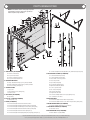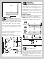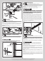
1
GARAGE DOORS & OPENERS
Models: 40, 42,
43, 45, 47
To r s i o n
6” Front Mount Low Headroom
MH
installation instructions and owner’s manual
Ta b l e
O f
C o n t e n t s
Parts Breakdown
Pre-Installation
Important Safety Instructions
Tools Required
Package Contents
Door Section Identification
Graduated End Hinge And Strut Identification
Removing an Existing Door
Preparing the Opening
Installation
Optional Installation
Door Arm Hookup
Lift Handles
Pull Down Rope
Maintenance
Cleaning Your Garage Door
Painting Your Garage Door
Clear Or Stained Finishes
Operation and Maintenance
Warranty
Dealer Locator Information
2
3
3
3
3
4
4
6
6
7
17
17
17
17
18
18
18
18
18
20
22
IMPORTANT NOTICES!
Wayne-Dalton highly recommends that you read and fully understand the Installation Instructions and Owner’s Manual before you
attempt this installation.
To avoid possible injury, read the enclosed instructions carefully before installing and operating the garage door. Pay close attention
to all warnings and notes. After installation is complete, fasten this
manual near garage door for easy reference.
The complete Installation Instructions and Owner’s Manual are available at no charge from:
Wayne-Dalton, a Division Of Overhead Door Corporation,
P.O. Box 67, Mt. Hope, OH., 44660,
Or Online At www.Wayne-Dalton.com
©Copyright 2012 Wayne-Dalton, a Division Of Overhead Door Corporation
Part No. 347615
REV1 03/08/2012
Parts Breakdown
NOTE: The illustrations shown on this page are general
representations of the door parts. Each specific door
models may have unique variations.
G5.
G11.
G7.
H2.
G9.
G12.
F1.
G2.
G1.
G5.
G3.
G12.
G6.
H1.
A1.
G4.
G9.
D1.
D1.
A2.
E1.
G5.
G10.
G8.
G4.
D1.
G5.
C1.
D1.
A1.
A2.
F6.
C2.
F4.
H2.
F3.
C2.
F1.
G13.
F7.
F2.
C3.
B3.
F6.
F4.
B2.
A2.
B1.
I1.
A4.
H1.
A1.
J1.
F7.
K1.
A3.
F3.
G13.
F5.
J1.
F2.
F5.
I1.
A. Track Rollers (As Required):
A1. Short Stem Track Rollers
A2. Long Stem Track Rollers
A3. Short Stem Tandem Track Rollers
A4. Long Stem Tandem Track Rollers
B. Graduated End Hinges:
B1. Single Graduated End Hinges (S.E.H.), Industry Standard
B2. Double Graduated End Hinges (D.E.H.), Industry Standard
B3. Half Center Hinges (As Required)
C. Stacked Sections:
C1. Top Section
C2. Intermediate(s) Section (As Required)
C3. Bottom Section
D. Top Fixtures (As Required):
D1. Top Fixtures
E. Strut (s), U-shaped (As Required):
E1. Strut (2” And Or 3”)
F. Tracks (As Required):
F1. Left Hand and Right Hand Horizontal Track Assemblies
F2. Left Hand and Right Hand Riveted Track Assemblies (As Required)
F3. Left Hand and Right Hand Wall Angle Track Assemblies (As Required)
F4. Left Hand and Right Hand Vertical Track Assemblies (As Required)
F5. Left Hand and Right Hand Vertical Tracks (As Required)
F6. Left Hand and Right Hand Fully Adjustable (F.A.) Flag Angles (As Required)
F7. Left Hand and Right Hand Fully Adjustable (F.A.) Jamb Brackets (As Required)
G. Torsion Spring Assembly (As Required):
G1. Center Bracket Bushing Assembly
G2. Center Bearing Bracket Assembly
G3. Torsion Shaft / Torsion Keyed Shaft
G4. Torsion Keyed Shafts
G5. Key Shafts (As Required)
G6. Left Hand End Bearing Bracket
G7. Right Hand End Bearing Bracket
G8. Center Coupler Assembly
G9. Set Collars (As Required)
G10. Left Hand Cable Drum
G11. Right Hand Cable Drum
G12. Left Hand and Right Hand Torsion Springs (As Required)
G13. Counterbalance Lift Cables
H. Rear Back Hangs:
H1. Left Hand and Right Hand Rear Back Hang Assemblies
H2. Left Hand and Right Hand Rear Center Back Hang Assemblies (As Required)
I. Bottom Corner Brackets (As Required):
I1. Left Hand and Right Hand Bottom Corner Brackets
J. Track Roller Carriers (As Required):
J1. Track Roller Carriers
K. Bottom Weather Seal (As Required):
K1. Bottom Weather Seal (Door Width)
2
Please Do Not Return This Product To The Store. Contact your local Wayne-Dalton dealer. To find your local Wayne-Dalton dealer,
refer to your local yellow pages business listings or go to the Find a Dealer section online at www.Wayne-Dalton.com
Pre-Installation
Important Safety Instructions
Tools Required
Definition of key words used in this manual:
• Power drill
• Drill bits: 1/8”, 3/16”,
9/32”, 7/16”, 1/2”
• Ratchet wrench
• Socket driver: 7/16”
• Sockets: 7/16”, 1/2”,
9/16”, 5/8”
WARNING
Indicates a potentially hazardous situation which; if not avoided,
could result in severe or fatal injury.
Caution: Property damage or injury can result from failure to follow
instructions.
Important: Required step for safe and proper door operation.
Note: Information assuring proper installation of the door.
READ THESE INSTRUCTIONS CAREFULLY BEFORE ATTEMPTING INSTALLATION. IF IN QUESTION
ABOUT ANY OF THE PROCEDURES, DO NOT PERFORM THE WORK. INSTEAD, HAVE A TRAINED
DOOR SYSTEMS TECHNICIAN DO THE INSTALLATION OR REPAIRS.
• Phillips head
screwdriver
• Locking Pliers
• (2) Vice clamps
• Wrenches: 3/8”,
7/16”, 1/2”, 9/16”,
5/8”
• 1/4” Torx bit
• Approved winding
rods
• Hammer
• Tape measure
• Step Ladder
• Level
• Pencil
• Leather gloves
• Safety glasses
Package Contents
1.
2.
3.
READ AND FOLLOW ALL INSTALLATION INSTRUCTIONS.
Wear protective gloves during installation to avoid possible cuts from sharp metal edges.
It is always recommended to wear eye protection when using tools, otherwise eye injury
could result.
4. Avoid installing your new door on windy days. Door could fall during the installation causing severe or fatal injury.
5. Doors 12’-0” wide and over should be installed by two persons, to avoid possible injury.
6. Operate door only when it is properly adjusted and free from obstructions.
7. If a door becomes hard to operate, inoperative or is damaged, immediately have necessary adjustments and/ or repairs made by a trained door system technician using proper
tools and instructions.
8. DO NOT stand or walk under a moving door, or permit anybody to stand or walk under an
electrically operated door.
9. DO NOT place fingers or hands into open section joints when closing a door. Use lift
handles/ gripping points when operating door manually.
10. DO NOT permit children to operate garage door or door controls. Severe or fatal injury
could result should the child become entrapped between the door and the floor.
11. Due to constant extreme spring tension, do not attempt any adjustment, repair or alteration to any part of the door, especially to springs, spring brackets, bottom corner brackets,
fasteners, counterbalance lift cables or supports. To avoid possible severe or fatal injury,
have any such work performed by a trained door systems technician using proper tools
and instructions.
12. On electrically operated doors, pull down ropes must be removed and locks must be
removed or made inoperative in the open (unlocked) position.
13. Top section of door may need to be reinforced when attaching an electric opener. Check
door and/ or opener manufacturer’s instructions.
14. Visually inspect door and hardware monthly for worn and or broken parts. Check to
ensure door operates freely.
15. Test electric opener’s safety features monthly, following opener manufacturer’s instructions.
16. NEVER hang tools, bicycles, hoses, clothing or anything else from horizontal tracks. Track
systems are not intended or designed to support extra weight.
17. This door may not meet the building code wind load requirements in your area. For your
safety, you will need to check with your local building official for wind load code requirements and building permit information.
After installation is complete, fasten this manual near the garage door.
Important: Stainless steel or pt2000 coated lag screws must be used when
installing center bearing brackets, end brackets, jamb brackets, drawbar operator mounting/ support brackets and disconnect brackets on treated lumber
(preservative-treated). Stainless steel or pt2000 lag screws are not necessary
when installing products on un-treated lumber.
Note: It is recommended that 5/16” lag screws are pilot drilled using a 3/16” drill bit, prior to
fastening.
Important: When installing 5/16” lag screws using an electric drill/ driver, the
drill/ drivers clutch must be set to deliver no more than 200 in-lbs of torque.
Fastener failure could occur at higher settings.
Note: Depending on the door model, some parts listed will not be supplied if not required. Rear
Back Hangs may not be included with your door.
Door sections (as required)
Torsion shaft / Torsion keyed shaft (as required)
Torsion keyed shafts (as required)
Fully Adjustable jamb
Fully Adjustable flag
brackets RH/LH (as required) angles RH/LH (as required)
Vertical tracks RH/LH (as required)
Vertical track assemblies RH/LH (as required)
Rivited vertical track assemblies RH/LH (as required)
Wall angle track assemblies RH/LH (as required)
Horizontal tracks RH/LH (as required)
Horizontal tracks RH/LH (as required)
WARNING
(2) Spacers
Prior to winding or making adjustments to the springs, ensure
you’re winding in the proper direction as stated in the Installation Instructions. Otherwise, the spring fittings may release
from spring if not wound in the proper direction and could
result in severe or fatal injury.
Track Roller Carriers
(as required)
Top fixtures
(as required) Strut (if included)
Important: Right and left hand is always determined from inside the building
looking out
3
Tandem track rollers
(if included)
Bottom corner
brackets (as required)
Please Do Not Return This Product To The Store. Contact your local Wayne-Dalton dealer. To find your local Wayne-Dalton dealer,
refer to your local yellow pages business listings or go to the Find a Dealer section online at www.Wayne-Dalton.com
Track rollers
Bottom corner
brackets (as required)
5/16” x 1-1/4”
Clevis pin (as required)
Cotter pin
(as required)
The BOTTOM SECTION can be identified by #1.
The INTERMEDIATE I SECTION can be identified by #2.
The INTERMEDIATE II SECTION can be identified by #3, for a 4 section high door only.
The INTERMEDIATE III SECTION can be identified by #4, for a 5 section high door only.
The INTERMEDIATE IV SECTION can be identified by #5, for a 6 section high door only.
The INTERMEDIATE V SECTION can be identified by #6, for a 7 section high door only.
The INTERMEDIATE III SECTION can be identified by #7, for a 8 section high door only.
The TOP SECTION can be identified by a #, being the highest section.
Top rail
Typical design option “Outside surface of
door sections shown”
Cable drums RH/LH Torsion springs RH/LH
End bearing
brackets RH/LH End bearing brackets Center bearing bracket Center bracket bushing
(as required) RH/LH (as required) assembly (as required) assembly (as required)
Center coupler
assembly (as required)
Key shafts
(as required)
Set collars
(as required)
Outside
surface
4. or 3.
Top
section
Counterbalance lift cables
3.
Intermediate II
section
Strut clips
(as required)
Hinges
Half Center
hinges (as required)
2.
Intermediate I
section
Weather seals
& nails (If included)
Lift handles
(as required)
#
Bottom
rail
Typical
stamping
location
1
Bottom
rail
Side views of sections
Top Intermediate(s) Bottom
section
section
1.
Bottom
section
Bottom weather seal with
3/4” nails (as required)
#
Inside
surface
NOTE: 3 Section high doors, does not have
an Intermediate II Section.
1/4”-20 x 9/16”
Pull down rope
(if included) Track bolts (as required)
Graduated End Hinge And
Strut Identification
(2) 3/8”-16 x 3/4”
Truss head bolts
1/4” - 14 x 1”
Lag screws (as required)
(2) 3/8”- 16 Hex nuts
Graduated End Hinge Schedule
Door Height
5/16” x 2” Tamper-resistant hex head
lag screw (as required)
Track
Section Type
Graduated End Hinge
Number
Top
N/A
2”
Intermediate I
#2
Bottom
#1
Top
N/A
Intermediate I
#4
3 Section High Door
3”
5/16” x 1 5/8” Hex head lag screws
(as required)
1/4”- 20 Flanged
hex nuts (as required)
2”
Bottom
#3
Top
N/A
Intermediate II
3#
Intermediate I
2#
Bottom
1#
Top
N/A
Intermediate II
5#
Intermediate I
4#
4 Section High Door
1/4” - 10 x 1” Tamper-resistant
hex head lag screw (as required)
3/8”-16 x 1-1/2” Hex bolts
3”
1/4” - 20 x 1 7/8”
Carriage bolts (as required)
2”
1/4”-20 x 7/8” Self
drilling screws (as required)
Bottom
3#
Top
N/A
Intermediate III
4#
Intermediate II
3#
Intermediate I
2#
Bottom
1#
Top
N/A
Intermediate III
6#
Intermediate II
5#
Intermediate I
4#
Bottom
3#
5 Section High Door
5/16” x 1 5/8” Hex head lag screws
(as required)
3”
Door Section Identification
When installing your door, you must use sections of the appropriate height in the right stacking
location. Determine, what sections you need to use in what order depends on the design of your
door.
Sections are stamped for identification, #1, #2, #3, #4, #5, #6, #7, and #8. The stamp, located
on each side of the sections identifies the stacking sequence. The sequence is always determined by #1 being the bottom section to #7 or #8 being the highest top section. If the stamp on
the section is illegible, refer to the section side view illustration. The section side view illustration
shows the section profile of all sections, and can also be used to identify each section.
4
Please Do Not Return This Product To The Store. Contact your local Wayne-Dalton dealer. To find your local Wayne-Dalton dealer,
refer to your local yellow pages business listings or go to the Find a Dealer section online at www.Wayne-Dalton.com
Graduated End Hinge Schedule
Top
2”
Intermediate IV
5#
Intermediate III
4#
Intermediate II
3#
Intermediate I
2#
Bottom
1#
6 Section High Door
3”
2”
Top
N/A
Intermediate IV
7#
Intermediate III
6#
Intermediate II
5#
Intermediate I
4#
Bottom
3#
Top
N/A
Intermediate V
6#
Intermediate IV
5#
Intermediate III
4#
Intermediate II
Intermediate I
7 Section High Door
3”
2”
1#
Top
N/A
Intermediate V
8#
7#
Intermediate III
6#
Intermediate II
5#
Intermediate I
4#
Bottom
3#
Top
N/A
Intermediate VI
7#
Intermediate V
6#
Intermediate IV
5#
Intermediate III
4#
Intermediate II
3#
Intermediate I
2#
Bottom
1#
Top
N/A
Intermediate V
Intermediate I
Bottom
Top
Intermediate I/II
Bottom
Top
Intermediate II/III
Intermediate I
Bottom
7#
6#
Intermediate II
5#
Intermediate I
4#
Bottom
3#
Bottom Of section
(1) Long
Top Of Section
N/A
Bottom Of section
N/A
Top Of Section
(1) Short
Bottom Of section
Type Of Strut
Top
Intermediate II/III/IV
Intermediate I
Bottom
Top Of Section
N/A
Bottom Of section
(1) Long
Top Of Section
N/A
Bottom Of section
N/A
Top Of Section
(1) Short
Bottom Of section
Type Of Strut
Top Of Section
N/A
Bottom Of section
(1) Long
Top Of Section
N/A
Bottom Of section
N/A
N/A
N/A
Top Of Section
(1) Short
Bottom Of section
Type Of Strut
Location On Section
(1) Short
Top Of Section
N/A
Bottom Of section
(1) Long
Top Of Section
N/A
Bottom Of section
N/A
N/A
N/A
Top Of Section
(1) Short
Bottom Of section
Top
Intermediate II/III/IV/V
Intermediate I
Bottom
Type Of Strut
Location On Section
(1) Short
Top Of Section
N/A
Bottom Of section
(1) Long
Top Of Section
N/A
Bottom Of section
N/A
N/A
N/A
Top Of Section
(1) Short
Bottom Of section
8 Section High Strutting Schedule
Section Type
Top
Intermediate II/III/IV/V/VI
Intermediate I
Bottom
Type Of Strut
Top Of Section
N/A
Bottom Of section
(1) Long
Top Of Section
N/A
Bottom Of section
N/A
N/A
N/A
Top Of Section
(1) Short
Bottom Of section
Location On Section
5
Location On Section
(1) Short
3 Section High Strutting Schedule
Type Of Strut
Location On Section
(1) Short
7 Section High Strutting Schedule
Section Type
NOTE: Center hinge(s) use #1 graduated end hinges at each pre-drilled vertical stile location.
The pre-drilled locations are located at the top and or bottom rails on the inside of the section
surface.
NOTE: Some doors will receive half center hinge(s). These will be installed in between the center
hinge(s) and graduated end hinge(s).
Strut Identification:
Identify your struts to determine which ones are long strut(s) or short strut(s).
Short Strut(s) are typically installed along the top rail of the top section and or along the bottom
rail of the bottom section.
Long Strut(s) are typically installed along the top and or bottom rails of sections. Measure the
height of the long strut(s) to determine if you have 2” or 3”.
NOTE: Some struts also may or may not have holes in them. If they don’t, then prior to installing
the strut and hinge to the section surface, you may have to drill a 3/16” hole for the appropriate
fastener on one or both sides of the strut legs.
Section Type
Location On Section
(1) Short
6 Section High Strutting Schedule
Section Type
8#
Intermediate III
Top Of Section
N/A
5 Section High Strutting Schedule
Section Type
9#
Intermediate IV
(1) Short
4 Section High Strutting Schedule
Section Type
2#
Bottom
Intermediate VI
Top
3#
Intermediate IV
8 Section High Door
3”
3 Section High Strutting Schedule
N/A
Please Do Not Return This Product To The Store. Contact your local Wayne-Dalton dealer. To find your local Wayne-Dalton dealer,
refer to your local yellow pages business listings or go to the Find a Dealer section online at www.Wayne-Dalton.com
Door Height
2” Strut
3” Strut
Short strut
Lower hinge
leaf
Hinges are stamped for
identification
2
1
Center hinge(s)
(as required)
1
Track
Motor Operated
102” (2591 mm)
125” (3175 mm)
7’1” to 8’0”
114” (2896 mm)
137” (3480 mm)
8’1” to 9’0”
Long strut
Upper hinge
leaf
Manual Lift
6’0” to 7’0”
126” (3200 mm)
168” (4267 mm)
9’1” to 10’0”
138” (3505 mm)
168” (4267 mm)
10’1” to 12’0”
162” (4115 mm)
*
12” Or 15” Radius
Headroom Requirements
Half center hinge(s)
(as required)
Removing an Existing Door
Track Type
Space Needed
6” LHR
9” (229 mm)
Suitable mounting surface
2”x 6” lumber minimum
Min. side room clearance for 2”
track is 3-1/2” (89 mm).
Min. side room clearance for 3”
track is 4-1/2” (114 mm).
Headroom
Header board 2”x 6”
lumber preferred
Important: Counterbalance spring tension must always be released before any
attempt is made to start removing an existing door.
WARNING
Min. side
room
clearance for
2” track is
3-1/2” (89
mm).
Min. side
room
clearance for
3” track is
4-1/2” (114
mm).
A powerful spring releasing its energy suddenly can cause severe
or fatal injury. To avoid injury, have a trained door systems technician, using proper tools and instructions, release the spring
tension.
For detailed information see supplemental instructions “Removing an Existing Door/ Preparing
the Opening”. These instructions are not supplied with the door, but are available at no charge
from Wayne-Dalton, A Division Of Overhead Door Corporation, P.O. Box 67, Mt. Hope, OH.,
44660, or at www.Wayne-Dalton.com.
Bac
kro
r
ade
l he
Nail
e
Lev
s
p
tri Finished
ers
Door
ath
We
Height
Plumb
jambs
ed
ish
Fin width
r
Doo
Preparing the Opening
bs
Jam
IMPORTANT: If you just removed your existing door or you are installing a new
door, complete all steps in preparing the opening.
To ensure secure mounting of track brackets, side and center brackets, or steel angles to new or
retro-fit construction, it is recommended to follow the procedures outlined in DASMA technical
data sheets #156, #161 and #164 at www.dasma.com.
The inside perimeter of your garage door opening should be framed with wood jamb and header
material. The jambs and header must be securely fastened to sound framing members. It is
recommended that 2” x 6” lumber be used. The jambs must be plumb and the header level.
The jambs should extend a minimum of 12” (305 mm) above the top of the opening for Torsion
counterbalance systems. For low headroom applications, the jambs should extend to the ceiling
height. Minimum side clearance required, from the opening to the wall, is 3-1/2” (89 mm), for
2” track. Minimum side clearance required, from the opening to the wall, is 4-1/2” (114 mm),
for 3” track.
Important: Closely inspect jambs, header and mounting surface. Any wood
found not to be sound, must be replaced.
For Torsion counterbalance systems, a suitable mounting surface (2” x 6”) must be firmly attached to the wall, above the header at the center of the opening.
Note: Drill a 3/16” pilot hole in the mounting surface to avoid splitting the lumber. Do not attach
the mounting surface with nails.
Weatherstrips (may not be included):
Depending on the size of your door, you may have to cut or trim the weatherstrips (if necessary)
to properly fit into the header and jambs.
Note: If nailing product at 40°F or below, pre-drilling is required.
Note: Do not permanently attach weatherstrips to the header and jambs at this time.
For the header, align the weatherstrip 1/8” to 1/4” inside the header edge, and temporarily
secure it to the header with equally spaced nails. Starting at either side of the jamb, fit the
weatherstrip up tight against the temporarily attached weatherstrip in the header and 1/8”
to 1/4” inside the jamb edge. Temporarily secure the weatherstrip with equally spaced nails.
Repeat for other side. This will keep the bottom section from falling out of the opening during
installation. Equally space nails approximately 12” to 18” apart.
Backroom requirement: Backroom is defined as the distance needed from the opening back
into the garage to allow the door to open fully.
*NOTE: For door heights from 10’1” to 14’0”, refer to your operator manufacture installation
instructions for appropriate depth into room.
Headroom requirement: Headroom is defined as the space needed above the top of the door
for tracks, springs, etc. to allow the door to open properly. If the door is to be motor operated,
2-1/2” (64 mm) of additional headroom is required.
Backroom Requirements
6
om
Jamb
Please Do Not Return This Product To The Store. Contact your local Wayne-Dalton dealer. To find your local Wayne-Dalton dealer,
refer to your local yellow pages business listings or go to the Find a Dealer section online at www.Wayne-Dalton.com
Weatherstrips
1/8” to 1/4”
Installation
1
Fully Adjustable Flag Angles
Tools: None
NOTE: If you have a wall angle track assembly or if you already have flag angles preattached to the vertical tracks, skip this step. Refer to Package Contents / Parts Breakdown,
to determine if you have flag angles.
Note: Flag angles are right and left handed.
If you have Fully Adjustable vertical tracks, hand tighten the left hand flag angle to the left
hand vertical track using (2) 1/4”-20 x 9/16” track bolts and (2) 1/4”-20 flange hex nuts.
Repeat for other side. Flange nuts will be secured after flag angle spacing is completed in
step, Top Section.
Flap
Bottom
weather seal
4
6”
Bottom Corner Brackets
Tools: Power Drill, 9/32” Drill Bit, Socket Driver 7/16”, Wrench 7/16”
WARNING
Failure to ensure tight fit of cable loop over cotter pin could
result in counterbalance lift cable coming off the pin, allowing the door to fall, possibly resulting in severe or fatal
injury.
1/4”- 20 x 9/16”
Track bolts
With the bottom section facing down from the previous step, uncoil the counterbalance lift
cables. Starting on the left hand side, place the cable loop into position between the two
holes on the side of the left hand bottom corner bracket. Slide a clevis pin through the innermost hole, cable loop, and outermost hole, of the bottom corner bracket. Slide a washer
onto the clevis pin and secure in place by inserting a cotter pin into the hole of the clevis pin.
Bend the ends of the cotter pin outwards to secure it in place. Repeat for other bottom corner
bracket. Repeat for other side.
(B) Left hand
(A) Left
bottom corner
hand
Counterbalance
bracket
bottom
lift cable
corner
bracket
Tools: None
NOTE: If you have a wall angle track assembly or if you already have jamb brackets preattached to the vertical tracks, skip this step. Refer to Package Contents / Parts Breakdown,
to determine if you have jamb brackets.
Note: The bottom jamb bracket is always the shortest bracket, while the center jamb
bracket is the next tallest. If three jamb brackets per side are included with your door, you will
have received a top jamb bracket, which is the tallest.
To attach the bottom jamb bracket, locate lower hole of the hole/ slot pattern of the 1st hole
set on the vertical track. Align the slot in the jamb bracket with the lower hole of the hole/ slot
pattern. Secure jamb bracket using (1) 1/4”-20 x 9/16” track bolt and (1) 1/4”-20 flange hex
nut. Repeat for other side.
Place the center jamb bracket over the lower hole of the hole/ slot pattern that is centered
between the bottom jamb bracket and flag angle of the 2nd hole set. Secure jamb bracket
using (1) 1/4”-20 x 9/16” track bolt and (1) 1/4”-20 flange hex nut. Repeat for other side.
If a top jamb bracket was included, secure it to vertical track using the lower hole of the hole/
slot pattern in the 3rd hole set and (1) 1/4”-20 x 9/16” track bolt and (1) 1/4”-20 flange hex
nut. Repeat for other side.
Vertical track Top of track
Lower hole of
hole/ slot pattern
Edge of
bottom
section
6”
3/4” Long galvanized roofing nails (not supplied)
Fully Adjustable Jamb Brackets
1st hole set
Bottom
weather
seal
Note: Refer to Door Section Identification / Parts Breakdown.
Fully Adjustable
vertical
track
2
Side
view
bottom
section
1”
Flag angle
1/4”-20
Flange hex nuts
Tools: Hammer, Tape Measure, Saw Horses
Note: If a bottom weather seal is supplied, complete this step.
Note: Refer to Door Section Identification / Parts Breakdown.
Place the bottom section face down on a couple of sawhorses or flat clean/ smooth surface.
Align the bottom weather seal with the flap pointing towards the outside surface of the bottom section.
Starting at one end of the door, measure inward 1” and attach the bottom weather seal to
the bottom of the bottom section with 3/4” long galvanized roofing nails (not supplied). Now
stretch the bottom weather seal slightly and nail the rest of the bottom weather seal to the
bottom of the bottom section every 6”.
Once the bottom weather seal is fastened cut off any extra material so that the bottom
weather seal is even with both ends of the bottom section.
NOTE: Verify bottom weather seal is aligned with bottom section. If there is more than 1/2”
excess weather seal on either side, trim weather seal even with bottom section.
Before installing your door, be certain that you have read and followed all of the instructions covered in the pre-installation section of this manual. Failure to do so may result in an
improperly installed door.
Important: Wood doors must be completely finished (3 total coats, including
primer coat) prior to installation, to ensure that the interior and exterior
surfaces, as well as all edges of the doors are properly protected against
moisture or other contaminants. Wood doors, in a non-finished condition,
must be transported and stored so the wood surfaces are NOT exposed
to moisture or other contaminants. Improper transportation, storage or
delays in finishing, that allows exposure of the wood door surfaces to moisture or other contaminants will result in the warranty being voided.
NOTE: Reference TDS 160 for general garage door terminology at www.dasma.com.
Bottom Weather Seal
3
2nd hole set
Washer
Clevis pin
(inserted through
cotter pin and
bent into place)
Washer
Cotter
pin
Next, starting on the left hand side, align the left hand bottom corner bracket horizontally with
the bottom edge of the bottom section and also align the bottom corner bracket vertically
with the left bottom edge of the bottom section. Using the bottom corner bracket as a template, mark and pre-drill 9/32” diameter holes through the bottom section. Attach the bottom
corner bracket to the bottom section using 1/4”-20 x 1-7/8” carriage bolts and 1/4”–20
flange hex nuts, as shown. Repeat the same process for other side. Mark and drill a pilot
holes 1” deep into the bottom section with a 1/8” drill bit. Secure the bottom corner brackets
to the bottom section using (1) 1/4”-14 x 1” tamper resistant lag screw, as shown. Repeat
the same process for the right hand side.
IMPORTANT: Be extremely careful not to drill thru the section. Only drill 1”
deep.
NOTE: All doors are provided with the tamper resistant fastener for the bottom corner brackets. However, the professional installer is most likely to have the proper tool to install this fastener. If the homeowner does not have the proper tool to install the tamper resistant fastener,
use a regular 1/4”-20 x 1-7/8” carriage bolt and a 1/4”–20 flange hex nut in its place.
If applicable, insert a short stem track roller into each of the bottom corner brackets, as
shown.
3rd hole set
1/4”- 20
Flange hex nut
F.A. jamb
bracket
1/4”- 20 x
9/16”
Track bolt
Cotter pin
Jamb bracket
in place
7
Please Do Not Return This Product To The Store. Contact your local Wayne-Dalton dealer. To find your local Wayne-Dalton dealer,
refer to your local yellow pages business listings or go to the Find a Dealer section online at www.Wayne-Dalton.com
(3) 1/4” - 20 x 1-7/8”
Carriage bolts
(3) 1/4” - 20
Flange hex nuts
Bottom
section
Bottom
section
Short
strut
Bottom corner
bracket
Typical left hand
bottom corner bracket
(1) 1/4” - 10 x 1” Tamper
resistant lag screw
1/4” - 14 x 1”
Lag screws
3/4”
(3) 1/4” - 20 x 1-7/8”
Carriage bolts
(3) 1/4” - 20
Flange hex nuts
Bottom
section
Typical left hand
bottom corner bracket
Track Roller Carriers
5
Tools: Power Drill, 9/32” Drill Bit, Socket Driver 7/16”, Wrench 7/16”
Starting on left hand side of the bottom section, attach the track roller carrier with the stamp
“STD” facing UP to the bottom corner bracket by aligning the four holes of the track roller
carrier with the four holes in the bottom corner bracket. Secure the track roller carrier to the
bottom corner bracket with (4) 1/4”-20 x 7/8” self drilling screws or (4) 1/4”-14 x 1” lag
screws.
NOTE: Depending on your door, some track roller carriers will use 1/4”-14 x 1” lag screws
instead of the 1/4”-20 x 7/8” self drilling screws to secure in place. If this is the case, mark
and pre-drill (4) 1/8” diameter holes and secure the track roller carrier to the bottom corner
bracket and bottom section using (4) 1/4”-14 x 1” lag screws.
Insert a short stem track roller and spacer into the inner holes. Repeat the same process for
the right hand side.
NOTE: The track roller carrier’s inner holes are used on doors with 2” track applications; the
outer holes are used on doors with 3” track applications.
Bottom corner
bracket
“STD”
facing UP
Bottom corner
bracket track
roller carrier
Short stem
track roller
Spacer
Bottom corner
bracket
Short
stem
track
roller
Bottom corner
bracket track
roller carrier
Spacer
(4) 1/4” - 20 x 7/8”
Self drilling screws
Side view of track roller
carrier(s)
Graduated End And Center Hinges
Tools: Power Drill, 1/8”/9/32” Drill Bit, Socket Driver 7/16”, Tape
NOTE: Refer to the Door Section Identification, Graduated End Hinge and Strut Identification,
to determine the appropriate hinges and or struts for your sections.
Using the appropriate graduated end hinges for the ends and depending on the width of your
door, enough center hinge(s) for each pre-drilled hole location.
Starting at the upper left hand corner of the bottom section. Position the lower hinge leaf of
the appropriate graduated end hinge onto the upper corner of the bottom section. Align the
slots of the lower hinge leaf with the pre-drilled holes or the factory installed threads in the
bottom section. Next, lay a long strut (if applicable) over the lower hinge leaf and over the top
rail of the bottom section. Center the long strut from side to side, as shown.
For single graduated end hinges without a strut:
Starting on the left hand side, attach the upper slot of the graduated end hinge to the bottom
section using (1) 1/4”-20 x 1-7/8” carriage bolt and (1) 1/4”–20 flange hex nut. Next, secure
the lower slot of the graduated end hinge to the bottom section using (1) 1/4”-20 x 1-7/8”
carriage bolt and (1) 1/4”–20 flange hex nut, as shown. Repeat same process for other side.
For single graduated end hinges with a strut (if applicable):
Starting on the left hand side, attach the upper slot of the graduated end hinge, (1) strut clip
and the upper leg of strut to the bottom section using (1) 1/4”-20 x 1-7/8” carriage bolt and
(1) 1/4”–20 flange hex nut. Next secure the bottom leg of strut, the lower slot of the graduated end hinge to the bottom section (1) 1/4”-20 x 1-7/8” carriage bolt and (1) 1/4”–20
flange hex nut, as shown. Repeat same process for other side.
For doors with double graduated end hinges:
Position the second graduated end hinge next to the first (single) graduated end hinge. Using
the second graduated end hinge as a template, drill pilot holes, 1” deep into the bottom
section with a 1/8” drill bit.
IMPORTANT: Be extremely careful not to drill thru the section. Only drill 1”
deep.
Attach the upper leg of strut (if applicable) to the upper slot of the graduated end hinge to the
bottom section using (1) 1/4”-14 x 1” lag screw. Next secure the bottom leg of strut (if applicable) to the lower slot of the graduated end hinge to the bottom section using (1) 1/4”-14
x 1” lag screw, as shown. Repeat same process for other side.
Double graduated end hinge
Single graduated end hinge
with long stem track roller
with short stem track roller
Lower hinge
Hinge
Long strut
Short
leaf(s)
tube(s)
(if applicable)
edge
(1) Strut clip
(if applicable)
(1) 1/4” - 10 x 1” Tamper
resistant lag screw
7
(4) 1/4” - 20 x 7/8”
Self drilling screws
Outer holes
(3” Track)
Long edge
(1) Strut clip
(if applicable)
Inner holes
(2” Track)
6
(2) 1/4” - 14 x 1”
Lag screws
(2) 1/4” - 20 x 1 7/8” Carriage bolts
and (2) 1/4” - 20 Flange hex nuts
Short edge
Hinge
tube(s)
Strutting
Tools: Power Drill, 1/8” Drill Bit, Socket Driver 7/16”, Tape Measure
Tandem
roller
NOTE: Refer to the Door Section Identification and Strut Identification, to determine if the
bottom section requires a short strut to be installed.
Lay the short strut onto the bottom rail of the bottom section. Position the bottom of the strut
3/4” up from the bottom edge of the bottom section. Center the short strut from side to side
on the section surface.
Drill pilot holes, 1” deep into the bottom section using a 1/8” drill bit.
IMPORTANT: Be extremely careful not to drill thru the section. Only drill 1”
deep.
Attach the strut using (2) 1/4”-14 x 1” lag screws at each on each end and center stile
(aligned with hinges) locations.
(1) Strut clip
(if applicable)
Short
edge
Typical
section
shown
Single graduated end hinge with
short stem tandem roller
Double graduated end hinge
with long stem tandem roller
Lower hinge
Long strut
leaf(s)
(if applicable)
Long edge
(1) Strut clip
(if applicable)
Short edge
(2) 1/4” - 14 x 1”
Lag screws
(2) 1/4” - 20 x 1 7/8” Carriage bolts
and (2) 1/4” - 20 Flange hex nuts
Typical
section
shown
For Center Hinges without a strut:
Starting on the left hand side, attach the upper slot of the center hinge to the bottom section
using (1) 1/4”-20 x 1-7/8” carriage bolt and (1) 1/4”–20 flange hex nut. Next, secure the
lower slot of the center hinge to the bottom section using (1) 1/4”-20 x 1-7/8” carriage bolt
and (1) 1/4”–20 flange hex nut, as shown. Repeat same process for other center hinges.
For Center Hinges with a strut (if applicable):
Starting on the left hand side, attach the upper slot of the center hinge, (1) strut clip and
8
Please Do Not Return This Product To The Store. Contact your local Wayne-Dalton dealer. To find your local Wayne-Dalton dealer,
refer to your local yellow pages business listings or go to the Find a Dealer section online at www.Wayne-Dalton.com
the upper leg of strut to the bottom section using (1) 1/4”-20 x 1-7/8” carriage bolt and
(1) 1/4”–20 flange hex nut. Next secure the bottom leg of strut, the lower slot of the center
hinge to the bottom section (1) 1/4”-20 x 1-7/8” carriage bolt and (1) 1/4”–20 flange hex
nut, as shown. Repeat same process for other center hinges.
Center hinge
Short
edge
(1) Strut clip
(2) 1/4” - 20 x 1 7/8” Carriage bolts
(if applicable)
(1) Strut clip
and (2) 1/4” - 20 Flange hex nuts
(if applicable)
(2) 1/4” - 20 x 1 7/8”
Carriage bolts
(2) 1/4” - 20
Flange hex nuts
Lower hinge leaf
Long edge
(C) Left hand
top fixture
Short stem
track roller
Long edge
(1) Strut clip
(if applicable)
(1) Strut clip
(if applicable)
Typical
section
shown
Short edge
Long strut
(if applicable)
(B): Position the second top fixture next to the first installed top fixture and loosely attach it
with (2) 1/4 – 14 x 1” lag screws. Insert a long stem track roller into the top fixture slides.
Repeat the same process for the right hand side.
(2) Top
fixtures
If you have single graduated end hinges, insert a short stem track roller / short stem tandem
track roller (if included) into the hinge tube on each side.
If you have double graduated end hinges, insert a long stem track roller / short stem tandem
track roller (if included) into the hinge tubes on each side.
Important: When placing track rollers / tandem track roller (if included)
into graduated end hinges number 2 and higher, the track roller / tandem
track roller (if included) goes into tube furthest away from section.
8
Top section
Top section
Long stem
track roller
(2) 1/4” - 14 x 1”
Lag screws
(D) Left hand
top fixture
Half Center Hinges
Tools: Power drill, 7/16” Socket driver, Tape measure
10 Note: If you don’t have half center hinges, then skip this step. Refer to Package Contents /
Parts Breakdown, to determine if you have half center hinges.
Using a tape measure, position the half center hinges equally spaced in between the center
hinges and equally spaced in between the center hinges and the graduated end hinges.
Position the holes of the lower hinge leaf onto the bottom section surface, as shown. Using
the half center hinge as a template, drill pilot holes, 1” deep into the bottom section using a
1/8” drill bit.
IMPORTANT: Be extremely careful not to drill thru the section. Only drill 1”
deep.
Attach the lower hinge leaf of the center hinge to the bottom section using (2) 1/4”-14 x 1”
lag screws. Repeat for other half center hinge(s). Set the bottom section aside.
Place the Intermediate I section face down on a couple of sawhorses or flat clean/ smooth
surface. Reference step Graduated End And Center Hinges and this step to attach the long
struts (if applicable) and hinges to the top rail of the sections in the same manner as was
done for the bottom section. Repeat the same process for the other Intermediate section(s) if
applicable, except top section.
Equally spaced
Half
Center
center
hinge
hinge
Typical section
Lower hinge leaf
shown
Strutting For Top Section
Tools: Power drill, 7/16” Socket driver
NOTE: Refer to the Door Section Identification and Strut Identification, to determine if the top
section requires a short strut to be installed.
Lay the short strut onto the top rail of the top section. Position the top of the strut 3/4” down
from the top edge of the top section. Center the short strut from side to side on the section
surface.
Drill pilot holes, 1” deep into the top section using a 1/8” drill bit.
IMPORTANT: Be extremely careful not to drill thru the section. Only drill 1”
deep.
Attach the strut using (2) 1/4”-14 x 1” lag screws at each on each end and center stile
(aligned with hinges) locations.
Short strut
Top section
3/4”
Typical top
fixture
1/4” - 14 x 1”
Lag screws
Long strut
(if applicable)
(2) 1/4” - 14 x 1” Lag screws
9
Top Fixtures
11 Tools: Power drill, 7/16” Socket driver
NOTE: If your door came with two top fixtures (A), then one top fixture and a short stem track
roller are required for each side.
NOTE: If your door came with four top fixtures (B), then two top fixtures and a long stem
track roller are required for each side.
Note: Refer to Door Section Identification / Parts Breakdown.
Place the top section face down on a couple of sawhorses or flat clean/ smooth surface.
NOTE: Depending on your door, refer to illustrations (A) or (B) to determine how to install the
top fixtures.
Follow the corresponding steps below:
(A): Starting on the left hand side, align the edge of the top fixture parallel to the top section
edge. Using the top fixture as a template, mark and pre-drill (3) 9/32” diameter holes through
the top section. Loosely attach the top fixture to the top section using (2) 1/4”-20 x 1-7/8”
carriage bolts and (2) 1/4-20 flange hex nuts. Insert a short stem track roller into the top
fixture slide. Repeat the same process for the right hand side.
Bottom Section
Tools: Level, Wooden shims (if necessary)
Center the bottom section in the door opening. Level the section using wooden shims (if
necessary) under the bottom section.
9
Please Do Not Return This Product To The Store. Contact your local Wayne-Dalton dealer. To find your local Wayne-Dalton dealer,
refer to your local yellow pages business listings or go to the Find a Dealer section online at www.Wayne-Dalton.com
13 Level
Bottom section
Wooden shims
(If necessary)
Vertical Tracks
Tools: Power Drill, 3/16” Drill bit, 7/16” Socket driver, Tape measure,
IMPORTANT: If your door is to be installed prior to a finishing construction
of the building’s floor, the vertical tracks and the door bottom section
assembly should be installed such that when the floor is constructed, no
door or track parts are trapped in the floor construction.
Important: The tops of the vertical tracks must be level from side to side.
If the bottom section was shimmed to level it, the vertical track on the
shimmed side must be raised the height of the shim.
Position the left hand vertical track assembly / wall angle track assembly over the track
rollers of the bottom section. Make sure the counterbalance lift cable is located between the
track rollers and the door jamb. Drill 3/16” pilot holes into the door jamb for the lag screws.
For flag angle track assemblies:
Loosely fasten jamb brackets and flag angle to the jamb using 5/16” x 1-5/8” lag screws, as
shown.
For wall angle track assembly:
Loosely fasten wall angle to the jamb using 5/16” x 1-5/8” lag screws, as shown.
If you have 2” vertical tracks:
Tighten lag screws, securing the bottom jamb bracket/bottom slot to jamb, maintain 3/8” to
5/8” spacing, between the bottom section and vertical track.
If you have 3” vertical tracks:
Tighten lag screws, securing the bottom jamb bracket/bottom slot to jamb, maintain 1/2” to
3/4” spacing, between the bottom section and vertical track.
Hang counterbalance lift cable over flag angle/wall angle. Repeat same process for other
side.
Wallangle
track
assembly
Typical graduated end
hinge with typical long
stem tandem track roller
Intermediate I section
Left double graduated
end hinge with typical
long stem track roller
Left single
graduated end
hinge with
typical short
stem track roller
5/16” x 1-5/8”
Lag screws
Typical sections shown
Flag
angle
Track
rollers
Vertical track
assembly
Center
hinge(s)
(2) 1/4”-14 x 1”
Lag screws
Lag
screw
locations
Bottom
section
Vertical
tracks
Bottom section
Right double graduated
end hinge with typical
long stem track roller
(2) 1/4”-20 x 1-7/8” Carriage bolts and (2) 1/4”-20 Flange hex nuts
Riveted track
flag angle
shown
Jamb
bracket
Tools: Power drill,7/16” Socket driver
Note: Make sure graduated end and center hinges are flipped down, when stacking another
section on top.
With assistance, lift intermediate I (second) section and guide the track rollers / tandem
rollers into the vertical tracks. Lower section until it is seated against bottom section. Keep
sections aligned. Repeat same process for other sections, except top section.
For Graduated end hinges and Center Hinges:
Starting with the outer graduated end hinges, flip the upper hinge leaf up and secure to the
section using (2) 1/4”-20 x 1-7/8” carriage bolts and (2) 1/4”–20 flange hex nuts. Repeat
same process for the center hinges.
If you have double graduated end hinges, flip the inner upper hinge leaf up and use it as a
template. Mark and pre-drill (2) 1/8” pilot holes, 1” deep into the section using a 1/8” drill bit.
Attach the upper hinge leaf to the section using (2) 1/4”-14 x 1” lag screws. Repeat same
process for other side.
If you have half center hinges:
Flip the upper hinge leaf up and use it as a template. Mark and pre-drill (2) 1/8” pilot holes,
1” deep into the section using a 1/8” drill bit. Attach the upper hinge leaf to the section using
(2) 1/4”-14 x 1” lag screws. Repeat same process for other half center hinges.
IMPORTANT: Be extremely careful not to drill thru the section. Only drill 1”
deep.
Important: Push & hold the hinge leafs securely against the sections while
securing with 1/4”-20 x 1-7/8” carriage bolts and 1/4”–20 flange hex nuts.
There should be no gap between the hinge leafs and the sections.
Weather seal
12 Stacking Sections
14 Bottom
section
3” Vertical track
spacing (1/2” to 3/4”)
Floor
Upper hinge leaf
Half center hinge
Long strut (if applicable)
Fully Adjustable Riveted
flag angle
flag angle
2” Vertical track
spacing (3/8” to 5/8”)
Right single
graduated end hinge
with typical short
stem track roller
Top Section
Tools: Hammer, Step ladder, Tape measure
Place the top section in the opening. Temporarily secure the top section by driving a nail into
the header near the center of the door and bending it over the top section. Now, flip up the
graduated end hinge and center hinge leaves, hold tight against section, and fasten center
hinges first and end hinges last (refer to step, Stacking Sections). Vertical track alignment
is critical. For 2” track, position flag angle/wall angle between 1-11/16” (43 mm) to 1-3/4”
(44 mm) from the edge of the door; tighten the bottom lag screw. For 3” track, position flag
angle/wall angle between 2-3/16” (56 mm) to 2-1/4” (57 mm) from the edge of the door;
tighten the bottom lag screw.
Flag angles/wall angles must be parallel to the door sections. Repeat same process for other
Track roller
10
Please Do Not Return This Product To The Store. Contact your local Wayne-Dalton dealer. To find your local Wayne-Dalton dealer,
refer to your local yellow pages business listings or go to the Find a Dealer section online at www.Wayne-Dalton.com
side.
Important: The dimension between the flag angles must be:
For 2” track applications: door width plus 3-3/8” (86mm) to 3-1/2” (89 mm) for
smooth, safe door operation.
For 3” track applications: door width plus 4-7/8” (124mm) to 5” (127 mm) for
smooth, safe door operation.
Complete the vertical track installation by securing the jamb bracket(s) or slots in the wall
angle and tightening the other lag screws. Push the vertical track against the track rollers so
that the track rollers are touching the deepest part of the curved side of the track; tighten all
the track bolts and nuts. Repeat for other side.
Door width (2” Track)
Door width (3” Track)
+ 3-3/8” to 3-1/2”
+ 4-7/8” to 5”
Top of flag angle or
Top of wallangle assembly
16 Top section
Horizontal
tracks
Top
section
Top section
17 Tools: Ratchet wrench, 7/16” Socket, 9/16” Socket, 9/16” Wrench,
To install horizontal track, place the curved end over the top track roller of the top section.
Align the bottom rail of the horizontal track with the top of the vertical track. Tighten the bottom rail of the horizontal track to the flag angle or wall angle with (2) 1/4”-20 x 9/16” track
bolts and (2) 1/4”-20 flange hex nuts.
Wall angle
(2) 1/4”-20
Flange hex nuts
Vertical
track
Flag angle
End Bearing Brackets
Tools: Step ladder, Power drill, 7/16” Socket driver
NOTE: Right and left hand is always determined from inside the garage looking out.
End bearing brackets are right and left hand.
Identify the end bearing brackets supplied with your door.
Align the bottom edge of left end bearing bracket with the top edge of the flag angle. Maintaining this alignment, also align the right edge of the end bearing bracket with the right edge
of the flag angle.
Secure the end bearing bracket to the jamb using (3) 5/16” x 1-5/8” lag screws, as shown.
Repeat same process for the other side.
Horizontal Tracks
Bottom rail of
horizontal track
(2) 1/4” - 14 x 1”
Lag screws
Track roller
Flag angle or
wallangle assembly
Vertical track
against rollers
15 Tools: 7/16” Wrench, Step ladder
With horizontal tracks installed, you can now adjust the top fixtures.
NOTE: If your door came with two top fixtures, then one top fixture is required to be adjusted
for each side.
NOTE: If your door came with four top fixtures, then two top fixtures are required to be
adjusted for each side.
Starting on the left hand side, vertically align the top section of the door with the lower sections. Maintaining the top fixture(s) position, tighten the 1/4”-20 flange hex nuts or 1/4”-20
x 1-3/8” bolts and or 1/4”-14 x 1” lag screws to secure the top fixture(s) to the top section.
Repeat for other side
Flag angle
Left hand top fixture(s)
Top
(2) 1/4” - 20 Flange hex nuts or
rail
(2) 1/4” - 20 x 1-3/8” bolts
Nail
2” Track Applications:
1-11/16” to 1-3/4”
3” Track Applications:
2-3/16” to 2-1/4”
Adjusting Top Fixtures
Left end bearing
bracket
Bottom rail of
horizontal track
Left end bearing
bracket
(3) 5/16” x 1-5/8”
Lag screws
(2) 1/4”-20
Flange hex nuts
(2) 1/4”-20 x 9/16”
Track bolts
Vertical
track
(2) 1/4”-20 x 9/16”
Track bolts
Top edge
of flag
angle
WARNING
Bottom
edge
Top
section
Top
section
Do not raise door until horizontal tracks are secured at rear,
as outlined in step, Rear Back Hangs, or door could fall from
overhead position causing severe or fatal injury.
Level the horizontal track assembly.
For riveted track assembly, bolt the top rail of the horizontal track to the first encountered slot
in the flag angle using (1) 1/4”-20 x 9/16” track bolt, (1) washer and (1) 1/4”-20 flange hex
nut.
For wall angle track assembly, first bolt the angle of the horizontal track to the slots in the
wall angle using (2) 3/8”-16 x 3/4” truss head bolts and (2) 3/8”-16 hex nuts. Now secure
the top rail of the horizontal track to the wall angle using (1) 1/4”-20 x 9/16” track bolt, (1)
washer and (1) 1/4”-20 flange hex nut.
Repeat for other side.
Remove the nail that was temporarily holding the top section in place, installed in step, Top
Section.
Important: Failure to remove nail before attempting to raise door could
cause permanent damage to top section.
(2) 3/8”-16 Hex nuts
(1) 1/4”-20 Flange hex nut
(2) 3/8”-16 x 3/4”
Truss head bolts
Washer
(1) 1/4”-20
Flange hex nut
Washer
Top rail of
horizontal track
Top rail of
horizontal track
(1) 1/4”-20 x 9/16”
(1) 1/4”-20 x 9/16”
Track bolt
Track bolt
Flag angle
Position the left hand end bearing bracket up against the jamb and the horizontal track, as
shown. Fasten the left hand end bearing bracket to the horizontal track with (1) 3/8”-16 x
3/4” truss head bolt and (1) 3/8”-16 nut. Secure the left hand end bearing bracket to the
jamb using (3) 5/16” x 1-5/8” lag screws. Repeat same process for the other side.
Left end bearing bracket
(3) 5/16” x 1-5/8”
Left end bearing
Lag screws
bracket
(1) 3/8”-16 x 3/4”
Truss head bolt
(1) 3/8”-16
Hex nut
Horizontal
track
Wall angle
11
Please Do Not Return This Product To The Store. Contact your local Wayne-Dalton dealer. To find your local Wayne-Dalton dealer,
refer to your local yellow pages business listings or go to the Find a Dealer section online at www.Wayne-Dalton.com
Upper
slot
Horizontal
track
18 NOTE: Identify the torsion springs provided as either right hand wound (red winding cone),
which goes on the RIGHT HAND SIDE or left hand wound (black winding cone), which goes on
the LEFT HAND SIDE.
For Doors without Coupler Assembly:
Facing the inside of the door lay the torsion shaft on the floor. Lay the torsion spring with the
black winding cone and the red cable drum at the left end of the torsion shaft. Lay the torsion
spring with the red winding cone and the black cable drum at the right end of the torsion
shaft.
NOTE: The set screws used on all torsion winding cones and cable drums are now colored
red. DO NOT identify right and left hand by the set screw color.
Slide the center bracket bushing or center bearing onto the torsion shaft followed by the
torsion springs.
IMPORTANT: The center bracket bushing or center bearing and torsion
springs, must be positioned, as shown.
With assistance, pick up the torsion spring assembly and slide one end of the torsion shaft
through one end bearing bracket. Lay the middle of the torsion shaft into the center bracket.
Slide the other end of the torsion shaft into the other end bearing bracket. Position the torsion
shaft so that equal amounts of the shaft extend from each end bearing brackets.
Center Bracket
Tools: Step ladder, Power drill, 7/16” Socket driver, 1/4” Torx bit, Level,
NOTE: Refer to the Package Contents and or Parts Breakdown to determine if your door
came with a coupler assembly.
NOTE: If your door came with a coupler assembly, the mounting surface needs to be a minimum of 17” wide. The (2) center bearing brackets will need to be spaced 12” to 14” apart, at
the center of the door, as shown.
Locate the center of the door.
If your door did not come with a coupler: Mark a vertical pencil line on the mounting surface
above the door, at the center.
If your door did come with a coupler: Mark a vertical pencil line on the mounting surface
above the door, at the center. Split the difference up and position the (2) center bearing
brackets apart from each other. Mark two vertical pencil lines, one for each center bearing
bracket onto the mounting surface above the door.
Measure from the center of the bearing, in one of the end bearing brackets, downwards,
to the top the door. Using that measurement, measure that distance upwards from the top
of the door to the mounting surface and mark a horizontal pencil line which intersects the
vertical pencil line(s). Align the edge of the center bracket(s) with the vertical pencil line and
the center of the center bracket(s) with the horizontal pencil line; this is to ensure the torsion
shaft is level between the center and end bearing brackets.
Attach the center bracket(s) to the mounting surface, using (2) 5/16” x 1-5/8” lag screws and
(1) 5/16” x 2” tamper-resistant lag screw.
IMPORTANT: Use a 5/16” x 1-5/8” tamper-resistant lag screw instead of the
5/16” x 2” tamper-resistant lag screw if mounting surface is mounted over
masonry. Tamper-resistant lag screw must be attached through the bottom
hole of the center bracket(s).
Typical
Mounting
Center of typical
Center of typical
center
surface
end bearing bracket
end bearing bracket
bracket
Black cable drum
(right hand side)
Center bushing
Right hand wound,
red winding cone
(right hand side)
Red cable drum
(left hand side)
Vertical
line
Horizontal
line
Equal distance from
top of door section
to horizontal line
Center bracket
bushing assembly
(2) 5/16” x 1-5/8”
Lag screws
Mounting
surface
Vertical
line
Left hand end
bearing bracket
Mounting
surface
Vertical
line
(2) 5/16” x 1-5/8”
Lag screws
Torsion shaft
Horizontal
line
Horizontal
line
(1) 5/16” X 2” or (1) 5/16” x 1-5/8” Tamper-resistant lag screw
Mounting surface
(17” Minimum)
Center
of
door
†
Horizontal
line
19 Center
bearing
bracket
assembly
(2) 5/16” x 1-5/8”
Lag screws
(2) 5/16” x 1-5/8”
Lag screws
(1) 5/16” X 2” or (1) 5/16”
x 1-5/8” Tamper-resistant
lag screw
Equal spacing
Center
bracket
bushing
Center bearing
Right hand end
bearing bracket
Center bracket
For Doors with a Coupler Assembly:
Disassemble the coupler assembly by removing the (3) 3/8”-16 x 1-3/4” hex head screws
and the (3) 3/8”-16 nylon hex lock nuts from the coupler halves. Loosen the set screws. Set
the components aside.
Facing the inside of the door, lay the (2) torsion keyed shafts on the floor. One torsion keyed
shaft on the left hand side and the other torsion keyed shaft on the right hand side.
Starting on the left hand side, lay one of the coupler halves, center bearing, the torsion spring
with the black winding cone, one set collar and the red cable drum at the left end of the torsion keyed shaft. Next on the right hand side, lay the other coupler halve, center bearing, the
torsion spring with the red winding cone, one set collar and the black cable drum at the right
end of the torsion keyed shaft.
NOTE: The set screws used on all torsion winding cones and cable drums are now colored
red. DO NOT identify right and left hand by the set screw color.
Slide the coupler halve, the center bearing onto the torsion keyed shaft followed by the torsion spring and the set collar.
IMPORTANT: The coupler halves, center bearings, torsion springs and the set
collars must be positioned, as shown.
Slide the flat edge of the couple halve flush with the side edge of the torsion keyed shaft.
Tighten the (2) set screws and the locking nut to secure the coupler halve to the torsion
keyed shaft.
NOTE: Tighten the set screws to 14-15 ft. lbs. of torque (once set screws contact the shaft,
tighten set screws one full turn).
Insert (1) key shaft into the slot of both the coupler halve and the slot in the torsion keyed
shaft, as shown. Repeat the same process for the other side.
With assistance and starting on the left hand side of door, pick up the left hand torsion spring
assembly and slide one end of the torsion keyed shaft through the end bearing bracket. Lay
the other side of the torsion keyed shaft into the center bracket. Repeat the same process for
the right hand torsion spring assembly.
Position both torsion keyed shafts so that equal amounts of the shafts extend from each end
bearing brackets.
Vertical line
Vertical
line
Torsion shaft or
Torsion keyed
shaft
Left hand wound,
black winding cone
(left hand side)
† (2) Center bearing
brackets spaced 6” to 7”
apart from the center of
the door.
Torsion Spring Assembly
Tools: Step Ladder
NOTE: Refer to the Package Contents and or Parts Breakdown to determine if your door
came with a coupler assembly.
IMPORTANT: Right and left hand is always determined from inside the building
looking out.
IMPORTANT: On single spring applications, only a right hand wound (red winding cone), which goes on the RIGHT HAND SIDE is required.
12
Please Do Not Return This Product To The Store. Contact your local Wayne-Dalton dealer. To find your local Wayne-Dalton dealer,
refer to your local yellow pages business listings or go to the Find a Dealer section online at www.Wayne-Dalton.com
Black cable drum
(right hand side)
Coupler
halves
Set screws
and Lock
nut
Center
coupler
assembly
(3) 3/8” - 16 x 1-3/4” Hex head screws
and (3) 3/8” - 16 Nylon hex lock nut
Red cable drum
(left hand side)
Torsion
keyed
shaft
Coupler
halves
Center bearing bracket(s)
Coupler
assembly
Center
bearing
Set
collar
Right hand wound,
red winding cone
Center (right hand side)
bearing
Key
Center bearing inside
torsion spring
Set screws
and Lock nut
Center
bearing
Left hand wound,
black winding cone
Set collar (left hand side)
Torsion keyed shaft
(2) 3/8”-16 Nuts
Right hand end
bearing bracket
Coupler
halve
Stationary spring cone
Equal
spacing
Left hand wound,
black winding cone
(left hand side)
Torsion
keyed
shaft
Tools: Step Ladder, 1/2” Wrench
21 If your door came with a Center Bracket Bushing:
Slide the center bracket bushing into the center bracket. Align the stationary spring cone(s)
with the holes in the center bracket bushing assembly.
If your door came with a Center Bearing Bracket(s):
Slide the center bearing into the spring. Align the stationary spring cone with the holes in the
center bearing bracket.
Secure the torsion spring to the center bracket bushing assembly or the center bearing
bracket assembly with (2) 3/8”-16 x 1-1/2” hex head bolts and (2) 3/8”-16 nuts. Repeat for
others, if applicable.
IMPORTANT: The spring warning tag(s) supplied must be securely attached
to the stationary spring cone(s) in plain view. Should a replacement spring
warning tag be required, contact Wayne-Dalton for free replacements.
For Doors with a Coupler Assembly:
At the middle of the two center bearing brackets, re-assemble the coupler assembly by
loosely fastening the coupler halves together using the (3) 3/8”-16 x 1-3/4” hex head screws
and the (3) 3/8”-16 nylon hex lock nuts, as shown.
NOTE: Ensure both torsion keyed shafts have equal amounts of the shafts extending from
each end bearing brackets.
Lock nuts
Torsion spring
Counterbalance Lift Cables
Tools: Step Ladder, Locking Pliers, 3/8” Wrench
Counterbalance lift
cable installed
Stationary
spring cone
Typical center
bracket bushing
Coupler
halves
Starting on the left hand side, thread the counterbalance lift cable up and around the front
side of the left hand cable drum.
IMPORTANT: Verify that there are no counterbalance lift cable obstructions.
Hook the counterbalance lift cable into the left hand cable drum. Starting on the left hand
side, slide the left hand cable drum onto the torsion shaft and up against the left hand end
bearing bracket. Counterbalance lift cable should provide a minimum of 1/2 pre-wrap on the
cable drum. Tighten the (2) set screws in the cable drum to 14-15 ft. lbs. of torque (once set
screws contact the shaft, tighten set screws one full turn).
NOTE: For doors with a torsion keyed shaft, insert (1) key shaft into the slot of both the cable
drum and the slot in the torsion keyed shaft, as shown.
Rotate the left hand drum and torsion shaft until counterbalance lift cable is taut. Now attach
locking pliers to the torsion shaft and brace locking pliers against the jamb to keep counterbalance lift cable taut. Repeat the same process for right hand side.
Now, secure the coupler assembly by tightening the (3) 3/8”-16 x 1-3/4” hex head screws
and the (3) 3/8”-16 hex nuts.
IMPORTANT: Inspect each counterbalance lift cables making sure they are
seated properly onto the cable drums and that both counterbalance lift
cables have equal tension.
Left hand
Jamb
end bearing
bracket
Stationary
spring cone
Typical center bracket
Torsion
keyed
shaft
(3) 3/8” - 16
nylon hex lock
nuts
(3) 3/8” - 16 x 1-3/4”
hex head screws
Torsion Spring Attachment
Torsion
spring
(2) 3/8”-16 x 1-1/2”
Hex head bolts
Center bearing brackets
Coupler
assembly
Set screws
Left hand end
bearing bracket
20 Torsion
spring
Torsion
spring
Torsion
keyed
shaft
Set collar
Typical center bracket
assembly
Coupler halves
assemblied
Center
bearing
Torsion
keyed
shaft
Torsion
keyed
shaft
Key
Center bearing
brackets
Equal spacing
Torsion
spring
Torsion
shaft
Locking
pliers
Spring
warning tags
Left hand
cable
drum
13
Please Do Not Return This Product To The Store. Contact your local Wayne-Dalton dealer. To find your local Wayne-Dalton dealer,
refer to your local yellow pages business listings or go to the Find a Dealer section online at www.Wayne-Dalton.com
Cable drum
set screws
Counterbalance lift cable
Center bearing brackets
Coupler
assembly
Set screws
Torsion
keyed
shaft
Torsion
keyed
shaft
(3) 3/8” - 16
nylon hex lock
nuts
24 Coupler
halves
WARNING
Torsion spring
Left hand end
bearing bracket
Key
Prior to winding or making adjustments to the springs, ensure
you’re winding in the proper direction as stated in the Installation Instructions. Otherwise the spring fittings may release
from spring if not wound in the proper direction and could
result in severe or fatal injury.
Left hand
cable drum
Alternately inserting the winding rods into the holes of the springs winding cone, rotate the
winding cone downward toward the floor, 1/4 turn at a time, until the required number of
complete turns for your door height is achieved. As the last 1/8 to 1/4 turn is achieved,
securely hold the winding rod while tightening both set screws in the winding cone to 14-15
ft. lbs. of torque (once set screws contact the torsion shaft, tighten screws one full turn).
Carefully remove winding rod from winding cone. Repeat for the opposite spring. While
holding the door down to prevent it from raising unexpectedly in the event the spring(s) were
over-wound, carefully remove the locking pliers from the torsion shaft and vertical tracks.
Adjustments to the number of turns stated may be necessary. If door rises off floor under
spring tension alone, reduce spring tension until door rests on the floor. If the door is hard to
rise or drifts down on its own, add spring tension.
NOTE: An unbalanced door such as this can cause garage door opener operation problems.
Torsion
keyed
shaft
22 Set Collars
Tools: Step Ladder, 3/8” Wrench
NOTE: If your door did not come with set collars, then skip this step.
Slide each of the set collars up against the inside surface of the end bearing brackets, with
the set screw facing directly away from the header. Tighten the set screw in each of the set
collars to the torsion shaft to 14-15 ft. lbs. of torque (once set screw contacts the shaft,
tighten set screw one full turn).
IMPORTANT: Prior to tightening the set screws in the set collars, avoid placing the set screws in the keyways of torsion keyed shaft(s).
Right End bearing
hand
bracket
cable
drum
Counterbalance Set
lift cable
collar
Torsion
keyed shaft
End
bearing
bracket
Set
collar
23 Tools: Step Ladder, Approved winding bars, 3/8” Wrench
Position a ladder slightly to the side of the spring so that the winding cone is easily accessible, and so your body is not directly in line with the winding bars.
IMPORTANT: Check the label attached to the spring warning tag for the
required number of complete turns to balance your door.
Lock nuts
(3) 3/8” - 16 x 1-3/4”
hex head screws
Winding Springs
Spring
Set screws
Torsion shaft
Set
screw
Approved
winding rods
Winding cone
Securing Door For Spring Winding(s)
Tools: Vice Clamps
25 With the door in the fully closed position, place vice clamps onto both vertical tracks just
above the third track roller. This is to prevent the garage door from rising while winding
springs.
Rear Back Hangs
Tools: Ratchet wrench, Socket: 1/2” 5/8”, Wrench: 1/2” 5/8”, (2) Vice
Important: Hold the door down to prevent it from rising unexpectedly in the
event the spring(s) was over-wound and cautiously remove vice clamps from
vertical tracks.
Raise the door until the top section and half of the next section are in the horizontal track
radius. Do not raise door any further since rear of horizontal tracks are not yet supported.
WARNING
Failure to place vice clamps onto vertical track can allow
door to raise and cause severe or fatal injury.
WARNING
Raising door further can result in door falling and cause
severe or fatal injury.
Clamp a pair of vice clamps onto the vertical tracks just above the second track roller on one
side, and just below the second track roller on the other side. This will prevent the door from
raising or lowering while installing the rear back hangs.
Using perforated angle (may not be supplied), (2) 5/16” x 1-5/8” hex head lag screws and
(3) 5/16” bolts with nuts (may not be supplied), fabricate rear back hangs for the horizontal
tracks. Attach the horizontal tracks to the rear back hangs with 5/16”-18 x 1 hex bolts and
nuts (may not be supplied).
NOTE: Doors heights over 8’0” or door widths over 11’0”, require an additional set of rear
center back hangs to be installed and located at the middle of the horizontal tracks, see parts
breakdown.
Using perforated angle (may not be supplied), (2) 5/16” x 1-5/8” hex head lag screws and (3)
5/16” bolts with nuts (may not be supplied), fabricate rear center back hangs for the horizontal tracks. Measure and drill a 3/8” diameter hole through the center length of the horizontal
track, as shown. Attach the rear center back hangs to the horizontal tracks with (1) 3/8” truss
head bolt and (1) 3/8” nut (may not be supplied).
Vice clamps above third
track roller on both sides of
door
Bottom section
Vice clamps attached to inner
and outer rail of vertical track
14
Please Do Not Return This Product To The Store. Contact your local Wayne-Dalton dealer. To find your local Wayne-Dalton dealer,
refer to your local yellow pages business listings or go to the Find a Dealer section online at www.Wayne-Dalton.com
WARNING
Keep horizontal tracks parallel and within 3/4” to 7/8” maximum of door edge, otherwise door could fall, resulting in
severe or fatal injury.
Important: Do not support the weight of the door on any part of the rear
back hangs that cantilevers 4” or more beyond a sound framing member.
Note: If rear back hangs are to be installed over drywall, use (2) 5/16” x 2” hex head lag
screws and make sure lag screws engage into solid structural lumber.
Note: 26” angle must be attached to sound framing members and nails should not be
used.
Now, permanently attach the weatherstrips on both door jambs and header. The weatherstrips were temporarily attached in Preparing the Opening, in the pre-installation section of
this manual.
NOTE: When permanently attaching the weatherstrips to the jambs, avoid pushing the weatherstrips too tightly against the face of door.
Horizontal tracks
Vice clamp
Vice clamp
2nd Track roller
WARNING
Prior to winding or making adjustments to the springs, ensure
you’re winding in the proper direction as stated in the Installation Instructions. Otherwise the spring fittings may release
from spring if not wound in the proper direction and could
result in severe or fatal injury.
Now, lift door and check its balance. Adjustments to the required number of spring turns
stated may be necessary. If door rises off floor under spring tension alone, reduce spring
tension until door rests on the floor. If the door is hard to rise or drifts down on its own, add
spring tension. A poorly balanced door can cause garage door operator operation problems.
To adjust spring tension, fully close door. Apply vice grips to track above third track roller.
Insert a winding rod into the winding cone. On single spring doors, counterbalance lift
cable tension must be maintained by placing vice grips on torsion shaft before loosening
set screws in the winding cone. Push upward on the winding rod while carefully loosening
the set screws in the winding cone. BE PREPARED TO SUPPORT THE FULL FORCE OF THE
TORSION SPRING ONCE THE SET SCREWS ARE LOOSE. Carefully adjust spring tension 1/4
turn. Retighten both set screws in the winding cone and repeat for the other side. Recheck
door balance DO NOT ADJUST MORE THAN 1/2 TURN FROM THE RECOMMENDED NUMBER
OF TURNS.
If door still does not balance correctly, contact a qualified door agency. If the door still does
not operate easily, lower the door into the closed position, UNWIND THE SPRING(S) FULLY
(Reference the insert “Removing The Old Door/Preparing The Opening” section on torsion
spring removal), and recheck the following the items:
1.) Check the door for level.
2.) Check the torsion shaft for level.
3.) Check the track spacing.
4.) Check the counterbalance lift cables for equal tension.
5.) Check the track for potential obstruction of the track rollers.
6.) Clamp locking pliers onto track and rewind springs.
IMPORTANT: If door still does not operate properly, then contact a trained
door system technician.
Sound framing
members
Perforated angle bolted
using (2) 5/16” x 1-5/8”
hex head lag screws to
ceiling member and
parallel to door
Horizontal
track
(3) 5/16” Bolts and nuts
Perforated angle
5/16”-18 x 1-1/4”
Hex bolts must extend into the
track to serve as a roller stop
Sound framing
members
(3) 5/16”
Bolts and nuts
Horizontal
track
Perforated angle
5/16”-18 x 1-1/4”
Hex bolts must extend into the
track to serve as a roller stop
15
Please Do Not Return This Product To The Store. Contact your local Wayne-Dalton dealer. To find your local Wayne-Dalton dealer,
refer to your local yellow pages business listings or go to the Find a Dealer section online at www.Wayne-Dalton.com
Perforated angle bolted
using (2) 5/16” x 1-5/8”
hex head lag screws to
ceiling member and
parallel to door
3/4” To 7/8”
3/4” To 7/8”
Door edges
Horizontal tracks
Rear center
back hang
Horizontal
track
(1) 3/8” Truss head bolt
(may not be supplied)
(1) 3/8” Nut
(may not be supplied)
Horizontal
track
Drill 3/8”
diameter hole
Center of the horizontal track
26 Label Placement
Tools: Step Ladder
IMPORTANT: Using the illustration, attach the appropriate labels to the appropriate location on the section, as shown.
NOTE: The Spring Warning tag(s) are factory attached (one per spring).
NOTE: Because of different configurations, some labels may require minor relocations.
Torsion spring tag(s) (one per spring)
HIGH SPRING TENSION CAN CAUSE
SERIOUS INJURY OR DEATH.
WARNING
DRILLING, SAWING, SANDING OR
MACHINING WOOD PRODUCTS GENERATES
WOOD DUST, A SUBSTANCE KNOWN TO THE
STATE OF CALIFORNIA TO CAUSE CANCER.
AVOID INHALING WOOD DUST OR USE A
RESPIRATOR OR OTHER SAFEGUARDS FOR
PERSONAL PROTECTION.
DO NOT REMOVE, COVER OR PAINT OVER
THIS LABEL. PRODUCT USER SHOULD
INSPECT THIS LABEL PERIODICALLY FOR
LEGIBILITY AND SHOULD ORDER A
REPLACEMENT FROM THE DOOR
MANUFACTURER AS NEEDED.
CALIFORNIA HEALTH AND SAFETY
CODE SECTION 25249.6
Residential Dust label
(For California Residents Only)
DO NOT adjust, repair or remove springs or
parts to which springs are connected, such
as steel brackets, cables, wood blocks,
fasteners or other parts of the
counterbalance system.
Adjustments or repairs must ONLY be made
by a trained door systems technician using
proper tools and instructions.
DO NOT remove, cover or paint over this tag.
Product user should inspect this tag
periodically for legibility and should order a
replacement tag from the door
manufacturer, as needed.
344648 NEW 11/19/2010
Wayne Dalton, a Division of
Overhead Door Corp.
P.O. Box 67
Mt. Hope, OH 44660
www.wayne-dalton.com
Wayne Dalton, a Division of
Overhead Door Corp.
3395 Addison Dr.
Pensacola, FL 32514
www.wayne-dalton.com
SAFETY INSTRUCTIONS
1. Operate door ONLY when it is properly
adjusted and free of obstructions.
2. If a door becomes hard to operate,
inoperative or is damaged, immediately
have necessary adjustments and/or repairs
made by a trained door system technician
using proper tools and instructions.
3. DO NOT stand or walk under a moving door,
or permit anybody to stand or walk under
an electrically operated door.
4. DO NOT place fingers or hands into open
section joints when closing a door. Use lift
handles/gripping points when operating
door manually.
5. DO NOT permit children to operate garage
door or door controls.
6. Due to constant extreme spring tension,
DO NOT attempt any adjustment, repair or
alteration to any part of the door,
especially to springs, spring brackets,
bottom corner brackets, red colored
fasteners, cables or supports. To avoid
possible severe or fatal injury, have any
such work performed by a trained door
system technician using proper tools and
instructions.
7. On electrically operated doors, pull down
ropes must be removed and locks must be
removed or made inoperative in the open
(unlocked) position.
8. Top section of door may need to be
reinforced when attaching an electric
opener. Check door and/or opener
manufacturer’s instructions.
9. VISUALLY inspect door and hardware
monthly for worn and/or broken parts.
Check to ensure door operates freely.
10. Test electric opener’s safety features
monthly, following opener manufacturer’s
instructions.
11. NEVER hang tools, bicycles, hoses, clothing
or anything else from horizontal tracks.
Track systems are not intended or designed
to support such extra weight.
Residential
warning label
Place label at a readable height on door. DO NOT
remove, cover or paint over this label. Product
user should inspect this label periodically for
legibility and should order a replacement label
from the door manufacturer as needed.
Copyright 2010 Wayne Dalton, a Division
of Overhead Door Corp.
324100
REV5 01/15/2010
WARNING
WARNING
Lift handles/gripping points are required
on this door, located as spelled out in the
installation instructions, even if the door
is motor operated.
Failure to install and use these lift handles/
gripping points on this door can result in
serious injury to fingers and/or hands, if
placed in the opening between sections,
when the door is operated manually.
WARNING
The adjacent bottom corner bracket and
all cable retention features including
milford pins, cotter pins, & clevis pins are
under HIGH SPRING TENSION.
Adjustments and repairs must only be
made by a trained door systems
technician, using proper tools and
instructions.
DO NOT REMOVE, COVER OR PAINT OVER
THIS LABEL. PRODUCT USER SHOULD
INSPECT THIS LABEL PERIODICALLY FOR
LEGIBILITY AND SHOULD ORDER A
REPLACEMENT FROM THE DOOR
MANUFACTURER AS NEEDED.
Wood label
important notice
IMPORTANT
THIS WOOD PRODUCT REQUIRES PROPER
FINISHING PRIOR TO ANY DOOR HARDWARE BEING
APPLIED. BOTH INNER AND OUTER FACES OF THE
SECTION(S), AS WELL AS ALL EDGE SURFACES
MUST BE PREPARED AND FINISHED IN STRICT
ACC0RDANCE TO THE DIRECTIONS GIVEN IN THE
INSTALLATION INSTRUCTIONS AND OWNER’S
MANUAL UNDER “MAINTENANCE AND PAINTING
INSTRUCTIONS FOR ALL WOOD DOORS”.
IMPROPER STORAGE, IMPROPER TRANSPORTATION
AND/OR DELAY IN FINISHING, THAT ALLOWS FOR
THE EXPOSURE OF THIS WOOD PRODUCT TO
MOISTURE AND/OR OTHER CONTAMINANTS, VOIDS
THE LIMITED WARRANTY.
316986
Bottom section warning labels
WARNING
The adjacent bottom corner bracket and
all cable retention features including
milford pins, cotter pins, & clevis pins are
under HIGH SPRING TENSION.
Adjustments and repairs must only be
made by a trained door systems
technician, using proper tools and
instructions.
DO NOT REMOVE, COVER OR PAINT OVER
THIS LABEL. PRODUCT USER SHOULD
INSPECT THIS LABEL PERIODICALLY FOR
LEGIBILITY AND SHOULD ORDER A
REPLACEMENT FROM THE DOOR
MANUFACTURER AS NEEDED.
16
Please Do Not Return This Product To The Store. Contact your local Wayne-Dalton dealer. To find your local Wayne-Dalton dealer,
refer to your local yellow pages business listings or go to the Find a Dealer section online at www.Wayne-Dalton.com
Optional Installation
WARNING
Door Arm Hookup
Tools: Needle nose pliers
Do not install pull down rope on doors with operators. Children
may become entangled in the rope causing severe or fatal injury.
At the center of the top section, measure horizontally from the top of center hinge to the bottom
of strut. Using that dimension, measure and cut (2) pieces of perforated angles. Assemble the
(2) pieces together using (2) 3/8” bolts and nuts (supplied by others). Now, secure to the top
section using carriage bolts and nuts (supplied by others), thru bolt both the perforated angles to
the top section, as shown.
Align the door arm with hole with one of the holes in the perforated angles. Secure the door
arm to the perforated angle using (1) 5/16” – 18 x 1” hex head bolt and (1) 5/16” – 18 lock nut
(supplied by others), as shown.
Measure and mark the jamb approximately 48” to 50” (1220 to 1270 mm) from floor on the
right or left side of jamb. Drill 1/8” pilot hole for no. 6 screw eye. Tie the pull down rope to the
no. 6 screw eye and to the bottom corner bracket, as shown.
No. 6 Screw eye
Typical bottom
bracket
Strut
Top
section
(2) 3/8” Hex bolt
and lock nut
(supplied by others).
(2) Perforated
angles
Carriage bolt
and nuts
(supplied by
others)
Center hinge
(1) 5/16” Hex bolt
and lock nut
(supplied by others).
48” to 50”
From floor
Typical
door arm
Pull rope
Pull rope
Lift Handles
Tools: Power drill, 1/8” Drill bit, Tape measure
NOTE: Lift handles must be lined up vertically.
Bottom Section:
Locate the exterior center stile or center most stile on the bottom section.
NOTE: For flush doors, find the center most stile by locating the center most hinge.
Using the bottom hole of the lift handle, measure up 3” from the bottom of bottom section. Mark
the hole locations and drill (2) 9/32” dia. holes through the bottom section. On the outside of
the door, insert (2) 1/4” - 20 x 2 1/2” carriage bolts (black head) into the outside lift handle and
insert the assembly into the (2) pre-drilled holes in the bottom section. From the inside, slide the
(2) holes in the inside lift handle over the stems of the carriage bolts. Secure the outside and
inside lift handle to the bottom section with (2) 1/4” – 20 flange hex nuts.
Intermediate I Section:
Locate the exterior center stile or center most stile on the Intermediate I section. Mark a vertical
line on the section at that point.
NOTE: Some Garage Doors may require both lift handles to be installed on bottom section. If
your bottom section height is 28” or 29”, install both lift handles onto the bottom section. Install
bottom lift handle per above instructions, then install the second lift handle a Minimum of 20”
and a Maximum of 30” above the bottom lift handle.
Measure up 4” from the bottom of the Intermediate I section. Using this measurement as a
guide, position the bottom hole of the lift handle bottom at the mark. Make a mark at the top
hole of the lift handle. This should give you a Minimum of 20” and a Maximum of 30” between
the lower lift handle and the middle of the top lift handle. If needed, reposition the lift handle to
stay within the Minimum and Maximum dimensions, as stated above.
Using the lift handle as a template, mark the hole locations and drill (2) 9/32” dia. holes through
the section. On the outside of the door, insert (2) 1/4” - 20 x 2 1/2” carriage bolts (black head)
into the outside lift handle and insert the assembly into the (2) pre-drilled holes in the section.
From the inside, slide the (2) holes in the inside lift handle over the stems of the carriage bolts.
Secure the outside and inside lift handle to the section with (2) 1/4” – 20 flange hex nuts.
(2) 1/4” - 20 x 2 1/2”
Lift
Carriage bolts and (2) 1/4” – 20
handle
Flange hex nuts
Intermediate I
section
Center
hinge
Bottom
section
Lift
handle
(2) 1/4” - 20 x 2 1/2”
Carriage bolts and (2) 1/4” – 20
Flange hex nuts
Strut
3”
Pull Down Rope
Tools: Power drill, 1/8” Drill bit, Tape measure
17
Please Do Not Return This Product To The Store. Contact your local Wayne-Dalton dealer. To find your local Wayne-Dalton dealer,
refer to your local yellow pages business listings or go to the Find a Dealer section online at www.Wayne-Dalton.com
Maintenance
Before you begin, read all warning labels affixed to the door and the installation instructions and
owner’s manual. When correctly installed, your Wayne-Dalton door will operate smoothly. Always
operate your door with controlled movements. Do not slam your door or throw your door into the
open position, this may cause damage to the door or its components. If your door has an electric
opener, refer to the owner’s manual to disconnect the opener before performing manual door
operation below.
Manual door operation:
For additional information on manual garage door operations go to www.dasma.com and
reference TDS 165.
IMPORTANT: DO NOT PLACE FINGERS OR HANDS INTO SECTION JOINTS WHEN OPENING
AND/OR CLOSING A DOOR. ALWAYS USE LIFT HANDLES / SUITABLE GRIPPING POINTS WHEN
OPERATING THE DOOR MANUALLY.
Opening a Door: Make sure the lock(s) are in the unlocked position. Lift the door by using the lift
handles / suitable gripping points only. Door should open with little resistance.
Closing a Door: From inside the garage, pull door downward using lift handles / gripping point
only or a high friction area only. If you are unable to reach the lift handles/ suitable gripping
points only, use pull down rope affixed to the side of door. Door should close completely with
little resistance.
Using an electric operator:
IMPORTANT: PULL DOWN ROPES MUST BE REMOVED AND LOCKS MUST BE REMOVED OR
MADE INOPERATIVE IN THE UNLOCKED POSITION.
When connecting a drawbar (trolley type) garage door operator to this door, an drawbar operator and or drawbar operator bracket must be securely attached to the top section of the door,
along with any struts provided with the door. Always use the drawbar operator and or drawbar
operator bracket supplied with the door. To avoid possible damage to your door, Wayne-Dalton
recommends reinforcing the top section on models 8000, 8100, 8200 and 9100 doors with a
strut (may or may not be supplied). The installation of the drawbar operator must be according
to manufacturer’s instructions and force settings must be adjusted properly. Refer to the owner’s
manual supplied with your drawbar operator for complete details on installation, operation,
maintenance and testing of the operator.
Maintaining Your Garage Door:
Before you begin, read all warning labels affixed to the door and the installation instructions
and owner’s manual. Perform routine maintenance steps once a month, and have the door
professionally inspected once a year. Review your Installation Instructions and Owner’s Manual
for the garage door. These instructions are available at no charge from Wayne-Dalton, A Division
Of Overhead Door Corporation, P.O. Box 67, Mt. Hope, OH., 44660, or at www.wayne-dalton.
com. For additional information on garage door/operator maintenance go to www.dasma.com
and reference TDS 151, 167 and 179.
Monthly Inspections:
1. Visual Inspection: Closely inspect jambs, header and mounting surface. Any wood found not
to be structurally sound must be replaced. Inspect the springs, counterbalance lift cables, track
rollers, pulleys, rear back hangs and other door hardware for signs of worn or broken parts.
Tighten any loose screws and/or bolts. Check exterior surface of the door sections for any minor
cracks. Verify door has not shifted right or left in the opening. If you suspect problems, have a
trained door system technician make the repairs.
Cleaning Your Garage Door
Important: Do not use a pressure washer on your garage door!
An annual inspection of all the surfaces of your garage door(s) will reveal the extent of weathering and the possible need for refinishing. When the finish becomes eroded or thin, clean and
prime any areas showing deterioration. Then completely refinish the door, according to the
directions, listed below, or the manufacturer’s label directions. Proper finishing of the wood
substrates to protect your door(s) from the effects of moisture and sunlight is vital in extending
the service life and beautifying your garage door(s).
The interior and exterior surfaces, as well as all edges must be properly primed, painted and
maintained, to protect and beautify your door. These finishing instructions are intended to
achieve both objectives for your wood doors(s).
Note: Be sure to clean behind weatherstrips on both sides and top of door.
Caution: Never mix cleansers or detergents with bleach.
Glass cleaning instructions
Clean with a mild detergent solution (same as above) and a soft cloth. After cleaning, rinse
thoroughly.
Acrylic cleaning instructions
Clean acrylic glazing with nonabrasive soap or detergent and plenty of water. Use your bare
hands to feel and dislodge any caked on particles. A soft, grit-free cloth, sponge or chamois may
be used to wipe the surface. Do not use hard or rough cloths that will scratch the acrylic glazing.
Dry glazing with a clean damp chamois.
Note: Do not use any window cleaning fluids, scouring compounds, gritty cloths or solventbased cleaners of any kind.
Clean all surfaces of dust, dirt and any other contaminants. Any scarring or stains that occur
during transportation, handling or storage must be re-sanded to the original condition.
Painting Your Garage Door
A high quality exterior 100% Acrylic Latex based finish paint is recommended for painting your
wood door. FOR BEST RESULTS DO NOT USE A DARK COLOR PAINT. HIGH HEAT ABSORPTION
CAN CAUSE EXCESSIVE BOWING AND CRACKING OF THE WOOD. If priming is necessary, prime
the interior and exterior surfaces, as well as all edges, using a primer compatible with the
selected finish paint and for the specific species of wood substrate being finished.
NOTE: Some species of wood, such as cedar, require special primers and finishes to prevent
tannin stains from appearing. Consult with your paint supplier.
If the door is factory primed by Wayne-Dalton, the priming step is not required, except if touchup is needed due to surface preparation and re-sanding.
NOTE: Wayne-Dalton uses a latex primer.
Finish paint the interior and exterior surfaces, as well as all edges with at least 2 coats of a high
quality exterior 100% Acrylic Latex finish paint over the primer. Follow paint manufacture’s label
directions explicitly for all coatings.
IMPORTANT: THE FOLLOWING TOP COATS ARE NOT RECOMMENDED. Shake and shingle
paints, clear coatings, oil or alkyd paints, vinyl acetate (PVA), vinyl acrylic or
vinyl acetate acrylic co-polymer paints.
WARNING
GARAGE DOOR SPRINGS, COUNTERBALANCE LIFT CABLES, BRACKETS, AND
OTHER HARDWARE ATTACHED TO THE SPRINGS ARE UNDER EXTREME TENSION, AND IF HANDLED IMPROPERLY, CAN CAUSE SEVERE OR FATAL INJURY.
ONLY A TRAINED DOOR SYSTEMS TECHNICIAN SHOULD ADJUST THEM, BY
CAREFULLY FOLLOWING THE MANUFACTURER’S INSTRUCTIONS.
Clear Or Stained Finishes
WARNING
If staining, select an exterior grade stain, approved for use on the species of wood substrates
being finished and compatible with Alkyd varnishes. FOR BEST RESULTS DO NOT USE A DARK
STAIN. HIGH HEAT ABSORPTION CAN CAUSE EXCESSIVE BOWING AND CRACKING OF THE
WOOD. Apply the stain to the interior and exterior surfaces, as well as all edges, following stain
manufacturer’s label directions. After proper drying time for the stain, or if wood is being left
natural, apply 1 coat of waterproof exterior Alkyd varnish (marine type varnish) to the interior
and exterior surfaces, as well as all edges. After recommended drying time of 1st coat, sand all
surfaces with fine grit (320) sandpaper. Clean all surfaces of sanding dust and apply a 2nd coat
of the Alkyd varnish to the interior and exterior surfaces, as well as all edges. After 2nd coat is
dry, sand all surfaces again with fine grit (320) sandpaper. Clean all surfaces of sanding dust
and apply a final 3rd coat of the Alkyd varnish to all surfaces.
Three finish coats of waterproof exterior Alkyd varnish are required to properly finish a stained
or natural wood door. Follow the finish manufacturer’s label directions explicitly for each coat
applied.
NOTE: Do not stain MDO plywood, apply paint only.
Only a waterproof exterior Alkyd varnish top coat finish is approved for stained or natural wood
doors. Other types of top coat finishes, including deck sealers, are not acceptable and if used,
will void the warranty.
NEVER REMOVE, ADJUST, OR LOOSEN THE BOLTS, SCREWS AND/OR LAG
SCREWS ON THE COUNTERBALANCE (END OR CENTER BEARING BRACKETS)
SYSTEM OR BOTTOM CORNER BRACKETS OF THE DOOR. THESE BRACKETS
ARE CONNECTED TO THE SPRING(S) AND ARE UNDER EXTREME TENSION. TO
AVOID POSSIBLE SEVERE OR FATAL INJURY, HAVE ANY SUCH WORK PERFORMED BY A TRAINED DOOR SYSTEMS TECHNICIAN USING PROPER TOOLS
AND INSTRUCTIONS.
Operation and Maintenance
Operating Your Garage Door:
18
TorqueMaster® Plus Springs: Pawl knob(s) (located on the TorqueMaster® end brackets above
the door) should be engaged to prevent the door from rapidly descending in case of spring
failure or forceful manual operation.
Torsion Springs: The torsion springs (located above the door) should only be adjusted by a
trained door systems technician. DO NOT attempt to repair or adjust torsion springs yourself.
Extension Springs: A restraining cable or other device should be installed on the extension spring
(located above the horizontal tracks) to help contain the spring if it breaks.
2. Door Balance: Periodically test the balance of your door. If you have a garage door drawbar
operator, use the release mechanism so you can operate the door by hand when doing this
test. Start with the door in the fully closed position. Lift the door to check its balance. Adjust
TorqueMaster® or Extension spring(s), if door lifts by itself (hard to pull down) or if door is difficult
to lift (easy to pull down). DO NOT attempt to repair or adjust Torsion Springs yourself. To adjust
TorqueMaster® or Extension spring(s), refer to your installation instructions and owner’s manual.
If in question about any of the procedures, do not perform the work. Instead, have it adjusted by
a trained door systems technician.
Please Do Not Return This Product To The Store. Contact your local Wayne-Dalton dealer. To find your local Wayne-Dalton dealer,
refer to your local yellow pages business listings or go to the Find a Dealer section online at www.Wayne-Dalton.com
3. Lubrication: The door should open and close smoothly. Ensure the door track rollers are
rotating freely when opening and closing the door. If track rollers do not rotate freely, clean the
door tracks, removing dirt and any foreign substances. Clean and lubricate (use a non-silicon
based lubricant) graduated end hinges, steel track rollers, spring(s) and bearings. DO NOT lubricate plastic idler bearings, nylon track rollers, door track. DO NOT oil a cylinder lock, if actuation
is difficult use a graphite dust to lubricate.
19
Please Do Not Return This Product To The Store. Contact your local Wayne-Dalton dealer. To find your local Wayne-Dalton dealer,
refer to your local yellow pages business listings or go to the Find a Dealer section online at www.Wayne-Dalton.com
Warranty
Limited warranty
Models: 40, 42, 43, 45, 47
Subject to the terms and conditions contained in this Limited Warranty, Wayne-Dalton (“Manufacturer”) warrants the sections of the door, against defects in
material and workmanship, for a period of ONE (1) YEAR from the time of delivery provided:
i)(i) The interior and exterior surfaces, as well as all edges of the wood door(s) are properly finished according to the Manufactures Maintenance and Painting
Instructions and finish manufacturer’s instructions. All surfaces of the wood door(s) must be completely finished (3 total coats, including primer coat) prior to
installation, to ensure that the interior and exterior surfaces, as well as all edges of the doors are properly protected against moisture or other contaminants.
Wood doors, in a non-finished condition, must be transported and stored so the wood surfaces are NOT exposed to moisture or other contaminants. If the door(s)
is not finished within TEN (10) DAYS of delivery, this warranty shall only extend to defects in workmanship and materials that appear within ONE (1) MONTH.
IMPROPER TRANSPORTATION, STORAGE OR DELAYS IN FINISHING, THAT ALLOWS EXPOSURE OF THE WOOD DOOR SURFACES TO MOISTURE OR OTHER CONTAMINANTS WILL RESULT IN THE WARRANTY BEING VOIDED.
The Manufacturer warrants the garage door hardware, tracks and springs of the above-described door, for a period of ONE (1) YEAR from the date of installation, against defects in material and workmanship, subject to all the terms and conditions below.
The Manufacturer will not be responsible for grain and color variations of natural wood. These natural variations in grain and color are not product defects, and
therefore will not be considered under this Limited Warranty.
The Manufacturer uses high quality material for framework, door skins, overlays, and panel materials. Exposure of wood to the environment may cause bowing,
checking and/or cracking of a door section regardless of efficiency of painting. This is not considered a defect; it is an uncontrollable characteristic of natural wood. The
dealer and the end user have the responsibility to select the type of material and/ or door which will offer the best results and longevity for the climate and/or environmental condition in which they will use the product.
This Limited Warranty is extended only to the person who purchased the product and continues to own the premises (where the door is installed) as his/her
primary residence (“Buyer”). This Limited Warranty does not apply to residences other than primary, or to commercial or industrial installations, or to installations on
rental property (even when used by a tenant as a residence). This Limited Warranty is not transferable to any other person (even when the premises is sold), nor does it
extend benefits to any other person. As a result this Limited Warranty does NOT apply to any person who purchases the product from someone other than an authorized
Wayne-Dalton dealer or distributor.
The Manufacturer will not be responsible for any damage attributable to improper storage, improper installation, or any alteration of the door or its components,
abuse, damage from corrosive fumes or substances, salt spray or saltwater air, fire, Acts of God, failure to properly maintain the door, or attempt to use the door, its
components or related products for other than its intended purpose and its customary usage. This Limited Warranty does not cover ordinary wear. This Limited Warranty
will be voided if any holes are drilled into the door, other than those specified by the Manufacturer.
THIS LIMITED WARRANTY COVERS A CONSUMER PRODUCT AS DEFINED BY THE MAGNUSON-MOSS ACT. NO WARRANTIES,
EXPRESS OR IMPLIED (INCLUDING BUT NOT LIMITED TO THE WARRANTY OF MERCHANTABILITY OR FITNESS FOR A PARTICULAR PURPOSE) WILL EXTEND BEYOND THE TIME PERIOD SET FORTH IN UNDERSCORED BOLD FACE TYPE IN THIS LIMITED WARRANTY, ABOVE.
•• Some States do not allow limitations on how long an implied warranty lasts, so the above limitations may not apply to you.
Any claim under this Limited Warranty must be made in writing, within the applicable warranty period, to the dealer from which the product was purchased. Unless the dealer is no longer in business, a written claim to the Manufacturer will be the same as if no claim had been made at all.
At the Manufacturer’s option, pursuant to the dealer having notified the Manufacturer of a warranty claim, a service representative may inspect the product on
site, or Buyer may be required to return the product to the Manufacturer at Buyer’s expense. Buyer agrees to cooperate with any representative of the Manufacturer and
to give such representative full access to the product with the claimed defect and full access to the location of its installation.
If the Manufacturer determines that the claim is valid under the terms of this Limited Warranty, the Manufacturer will cause the defective product to be repaired
or replaced. The decision about the manner in which the defect will be remedied will be at the discretion of the Manufacturer, subject to applicable law. THE REMEDY
WILL COVER ONLY MATERIAL. THIS LIMITED WARRANTY DOES NOT COVER OTHER CHARGES, SUCH AS FIELD SERVICE LABOR FOR REMOVAL, INSTALLATION, PAINTING,
SHIPPING, ETC.
Any repairs or replacements arranged by Manufacturer will be covered by (and subject to) the terms, conditions, limitations and exceptions of this Limited Warranty; provided, however, that the installation date for the repaired or replaced product will be deemed to be the date the original product was installed, and this Limited
Warranty will expire at the same time as if there had been no defect. If a claim under this Limited Warranty is resolved in a manner other than described in the immediately preceding paragraph, then neither this Limited Warranty nor any other warranty from the Manufacturer will cover the repaired or replaced portion of the product.
THE REMEDIES FOR THE BUYER DESCRIBED IN THIS LIMITED WARRANTY ARE EXCLUSIVE and take the place of any other remedy. The liability of the Manufacturer, whether in contract or tort, under warranty, product liability, or otherwise, will not go beyond the Manufacturer’s obligation to repair or replace, at its option, as
described above. THE MANUFACTURER WILL NOT UNDER ANY CIRCUMSTANCES BE LIABLE FOR SPECIAL, INCIDENTAL, OR CONSEQUENTIAL DAMAGES, including (but
not limited to) damage or loss of other property or equipment, personal injury, loss of profits or revenues, business or service interruptions, cost of capital , cost of
purchase or replacement of other goods, or claims of third parties for any of the foregoing.
•• Some States do not allow the exclusion or limitation of incidental or consequential damages, so the above limitation or exclusion may not apply to you.
No employee, distributor, dealer, representative, or other person has the authority to modify any term or condition contained in this Limited Warranty or to grant
any other warranty on behalf of or binding on the Manufacturer, and anyone’s attempt to do so will be null and void.
Buyer should be prepared to verify the date of installation to the satisfaction of the Manufacturer.
The rights and obligations of the Manufacturer and Buyer under this Limited Warranty will be governed by the laws of the State of Ohio, USA, to the extent
permitted by law.
•• This Limited Warranty gives you specific legal rights and you may also have other rights, which may vary from State to State.
**NOTE: Variations in color or graining of natural wood is not considered a product defect, and therefore not covered under the limited warranty.
**Grain and color variations are inherent to natural wood. These natural variations in grain and color are not product defects and therefore will not be considered
under Wayne-Dalton’s limited warranty.
20
Please Do Not Return This Product To The Store. Contact your local Wayne-Dalton dealer. To find your local Wayne-Dalton dealer,
refer to your local yellow pages business listings or go to the Find a Dealer section online at www.Wayne-Dalton.com
Covered by one or more of the following Patents; 5,408,724; 5,409,051; 5,419,010; 5,495,640; 5,522,446; 5,562,141; 5,566,740; 5,568,672;
5,718,533; 6,019,269; 6,089,304; 6,644,378; 6,374,567; 6,561,256; 6,527,037; 6,640,872; 6,672,362; 6,725,898; 6,843,300; 6,915,573;
6,951,237; 7,014,386; 7,036,548; 7,059,380; 7,121,317; 7,128,123; 7,134,471; 7,134,472; 7,219,392; 7,254,868. Canadian: 2,384,936;
2,477,445; 2,495,175; 2,507,590; 2,530,701; 2,530,74; 2, 2,532,824. Other US and Foreign Patents pending.
Please Do Not Return This Product To The Store
Contact your local Wayne-Dalton dealer. To find your local Wayne-Dalton dealer, refer to your local yellow pages
business listings or go to the Find a Dealer section online at www.Wayne-Dalton.com
Thank you for your purchase.
After installation is complete, fasten this manual near THE garage door.