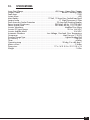
1
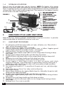
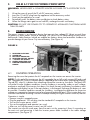
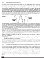
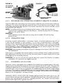
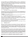
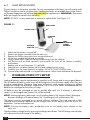
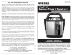
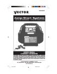
VEC029ACY
™
®
MULTI-FUNCTION
AC/DC JUMP-START SYSTEM
VEHICLE JUMP-STARTER • 200 WATT INVERTER
120 PSI AIR COMPRESSOR • WORKLIGHT/LANTERN
OWNER’S MANUAL
& WARRANTY INFORMATION
THIS MANUAL CONTAINS IMPORTANT INFORMATION REGARDING SAFETY, OPERATION,
MAINTENANCE AND STORAGE OF THIS PRODUCT. BEFORE USE, READ AND
UNDERSTAND ALL CAUTIONS, WARNINGS, INSTRUCTIONS AND PRODUCT LABELS, PLUS
YOUR VEHICLE’S BATTERY MANUFACTURER GUIDELINES. FAILURE TO DO SO COULD
RESULT IN POSSIBLE INJURY OR PROPERTY DAMAGE.
4140 S.W. 30TH AVE., FT. LAUDERDALE, FL 33312
TEL: 954-584-4446 • FAX: 954-584-5556 • Toll-free: 866-584-5504
www.vectormfg.com
1
IMPORTANT SAFETY INSTRUCTIONS
Read and Understand all Warnings, Cautions and Notes before operating Power City.
Warnings alert the user to hazardous conditions that can be harmful to people. Cautions alert
the user to conditions that can cause property damage. Notes are important operational
information.
KEEP THIS USER’S GUIDE FOR FUTURE USE.
JUMP-START WARNINGS AND CAUTIONS
• There is risk of explosive gas being released when batteries are improperly charged
or discharged. Failure to follow instructions may cause property damage, explosion
hazard and/or personal injury
• Do not smoke while jump-starting
• Only attempt to jump-start a vehicle or boat in a well ventilated area
• This power system is to be used ONLY on vehicles or boats with 12 volt DC
battery systems
• Do not wear vinyl clothing when jump-starting a vehicle - friction can cause dangerous
static electricity sparks
• Remove all metal jewelry - this can cause short circuits. Always use protective eyewear
when jump-starting: contact with battery acid may cause blindness and/or severe burns.
• Never touch Power City red and black clamps together - this can cause dangerous
sparks, power arcing and/or explosion
• Do not attempt to jump-start a frozen battery
• After use as jump-starter, turn off safety switch
• Keep out of reach of children
• Vehicles that have on-board computerized systems may be damaged if vehicle battery
is jumpstarted. Before jump-starting this type of vehicle, read the vehicle’s owner’s
manual to confirm that external-starting assistance is advised
• Excessive engine cranking can damage the vehicle’s starter motor. If the engine fails to
start after the recommended number of attempts, discontinue jumpstart procedure and
look for other problems that may need to be corrected
• When safety switch is off, Polarity Alarm is enabled. If cables are connected to
another battery and the alarm sounds, the cable connections must be switched. If alarm
sounds, do not turn on safety switch
• If vehicle to be started has a positive grounded System (positive battery terminal is
connected to chassis), replace steps 9 and 10 of the jump-start procedure (below) with
the following steps A and B, and then proceed to step 11
A. Connect negative (-) black clamp to vehicle battery ‘s negative terminal.
B. Connect positive (+) red clamp to vehicle chassis or a solid, non-moving, metal
vehicle component or body part. DO NOT clamp directly to positive battery
terminal or moving part.
• Replace worn or defective parts immediately - contact Vector Technical Support
Department at toll-free 866-584-5504
• Skin: if battery acid comes in contact with skin, rinse immediately with water, then wash
thoroughly with soap and water. If redness, pain, or irritation occurs, seek immediate
medical attention
• Eyes: if battery acid comes in contact with eyes, flush eyes immediately for a minimum
of 15 minutes, seek immediate medical attention.
2
CONTENTS
1. INTRODUCTION ...................................................... 4
1.1 General discription .............................................................................. 4
1.2 Key features ........................................................................................ 5
1.3 Use Power City to ................................................................................ 5
1.4 Storage location .................................................................................. 6
2. USE AS A JUMP-START SYSTEM .................................... 6
2.1 Jumpstart warnings .............................................................................. 6
3. USE AS A 12 VOLT DC PORTABLE POWER SUPPLY ......... 7
4. POWER INVERTER ........................................................ 7
4.1 Inverter operations ............................................................................... 7
4.2 Principles of operations ........................................................................ 8
4.3 Connecting Inverter to power source away from main unit ...................... 8
4.3.1 Procedure for connecting inverter to remote DC source ........................ 9
4.3.2 Operating time ................................................................................. 9
4.4 Powering an AC load .......................................................................... 9
4.5 Placement of the power inverter ............................................................ 10
4.6 Operating tips ..................................................................................... 10
4.7 Inverter fuse replacement ...................................................................... 11
5. COMPRESSOR/TIRE INFLATOR ...................................... 11
5.1 Compressor use ................................................................................... 11
5.2 Warnings ............................................................................................ 11
5.3 Tire Inflation or products with a valve stem ............................................. 12
5.4 Inflate other articles (without valve stem) ................................................ 12
5.5 Typical inflation times ........................................................................... 12
6. LANTERN USE ............................................................. 12
6.1 Lantern operation on main unit ............................................................. 12
6.2 Lantern operation detached from main unit ............................................ 13
6.2.1 Lantern operation from DC source ...................................................... 13
6.2.2 Lantern operation 120 volt with AC recharge adapter ......................... 13
6.3 Lamp replacement ............................................................................... 14
7. RECHARGING POWER CITY’S BATTERY..................... 14
7.1 AC recharging ................................................................................... 15
7.2 DC recharge ....................................................................................... 15,16
7.3 Alternate DC recharge ......................................................................... 16
7.4 Simultaneous DC recharge and inverter operation.................................. 16
8. MAINTENANCE/REPLACEMENT PARTS..................... 16
9. BATTERY DISPOSAL AND WARNINGS ...................... 16
10. SPECIFICATIONS ...................................................... 17
11. WARRANTIES........................................................... 18
3
1.
INTRODUCTION
Congratulations on selecting the Vector Power City® Multi-Function AC/DC Power System. Power City is an advanced power and jump-start system with unique features that
set it far above the value and utility of ordinary jump-starters. It supplies AC for 120 volt
appliances to 200 watts, and DC for 12 volt appliances to 23 amps. It can jumpstart any vehicle
with a standard 12 volt DC electrical system: boat, truck, car, airplane, RV, personal watercraft,
snowmobile, tractor, etc. See Figure 1.
2
FIGURE 1
12
3
1
4
11
9
10
7
1.1
8
GENERAL DESCRIPTION
6
5
1. INVERTER COVER
2. RETRACTABLE HANDLE
3. LANTERN ASSEMBLY
LATCH
4. LANTERN ON/OFF
SWITCH
5. 12V ACCESSORY
SOCKETS
6. MAIN POWER
SAFETY SWITCH
7. CHARGE STATUS
DISPLAY
8. CHARGE STATUS
PUSHBUTTON
9. NEG. (BLACK) CLAMP
10. POWER INVERTER
11. COMPRESSOR GAUGE
12. POS. (RED) CLAMP
This advanced design is ideal for emergencies and can also enhance your fun by powering
appliances on the road and at the campsite. Be sure to read and understand all WARNINGS and
CAUTIONS before using this product. Please read this guide carefully before use to ensure optimum
performance and avoid damage to the system or items that you are using it with.
Power City ® has several exclusive features that set it apart from other similar devices.
Primarily, it includes a special, patented, built-in mounting for a supplied, removable 12 VDC
to 120 volt AC power inverter. This allows you to operate 120 volt AC devices to 200 watts,
while still maintaining the jump-starter’s one-piece, compact styling. When the inverter is
removed from the main unit it can be fully powered from any accessory socket that can provide up to
23 amperes at 12 VDC.
A removable Lantern operates from Power City’s self-contained battery. It can be operated attached to the main unit or removed from the Main Unit. Away from the Main Unit, the
Lantern is powered using an extension cord attached to the Inverter power cable. This feature is
invaluable when it becomes necessary to locate battery terminals while preparing to jumpstart a dead
battery in the dark, changing a tire, etc.
Power City is also ideal to power 12 volt DC cordless, portable, rechargeable appliances with
ratings up to 23 amperes. For information about Vector appliances, contact Vector Customer
Support for the location of the nearest retailer.
The unit has an easy-to-read, series of LEDs (light emitting diodes) arranged as a charge status display
that shows when the unit is fully charged or the level of charge in the battery (from low to full). The
charge status display activates whenever the charge status pushbutton is pressed or automatically during
AC recharge operations. Two 12 volt DC outlets are provided for use with appliances that can operate
from the accessory outlet. NOTE: that all exposed electrical sockets recharge ports have covers that
help keep out dirt, dust and moisture.
Another feature is the high pressure, self-contained air compressor. This compressor allows quick
inflation of tires, sports balls and other small inflatables. An easy-to-read analog pressure gauge
allows accurate pressure readings, so there’s no guesswork about critical tire pressures. Now there
is no excuse for driving on under, or over-inflated tires. Three different types of adapter nozzles
allow for easy connection to all popular inflatables. A compressor on/off slide switch located
between the jump-start clamps controls operation of the compressor. The air compressor hose and
connector nozzle are stored on the back of the unit. (See Figure 3)
4
5
4
FIGURE 2
1. NEGATIVE (BLACK)
CLAMP
2. AIR COMPRESSOR
ON/OFF SWITCH
3. AC RECHARGE PORT
4. POSITIVE (RED) CLAMP
5. AIR COMPRESSOR
PRESSURE GAUGE
6. 120 VOLT AC CHARGER
1.2
3
2
1
6
KEY FEATURES
• On/off safety power switch (no key required, no key to get lost!)
• Cordless/rechargeable-includes recharge adapters for standard 120 volt AC wall socket
and vehicle’s 12 volt DC accessory outlet using adapter cables
• Powerful 400 boost amps; 1200 peak amps
• Includes non-spillable, maintenance-free, heavy duty, 19 ampere hour, sealed, lead-acid battery
• Audible polarity alarm to warn of reverse polarity
• Requires no maintenance (other than recharging) for optimum operation
• Heavy duty, industrial grade copper clamps and #4 AWG jumper cables-with exclusive
recessed cable holsters
• Built-in 120 PSI compressor with lighted gauge
• Built-in, removable fluorescent lantern
• Storage channels that keep jumper cables and the compressor hose out of the way until they
are needed and allow Power City to securely lay against flat surfaces
• 110 volt AC charger is Underwriter Laboratories safety tested and listed
• Easy-to-read LED battery charge status display - activated by pressing the charge status
button and automatically activated during AC recharge
1.3
USE POWER CITY TO:
• Jump-start (using heavy duty battery cable and clamps) any vehicle with a standard 12 volt
DC battery system: boat, truck, car, airplane, RV, personal watercraft, snowmobile, tractor, etc.
• Power/recharge: AC laptop computers and printers, color TVs up to 13”, reading lamps,
fans, small appliances and power hand tools, cellular phones, camcorders, power tool
rechargeable batteries that have an appropriate recharging adapter with a 120 volt AC
standard-type plug
• Operate (using 23 ampere rated 12 volt accessory sockets): 12 volt DC fans, fluorescent
worklights, air compressors, spotlights, TVs, portable radios, cassette or CD players and
more. Can operate and quick-charge a cellular phone by using the phone’s 12 volt DC
adapter cord
• Inflate truck, auto, motorcycle and trailer tires and small popular beach and camping
accessories such as volley balls, soccer beach balls, saving valuable time and effort
• Illuminate areas: under the hood, inside tents, work areas while changing tires, etc. Lantern
is removed from main unit and powered by an extension cord, for light where you need it
NOTE: Other appliances may also be used with the Power City as long as they do not exceed
the 23 ampere limit of the units 12 volt DC accessory outlet, or the 200 watt limit of the
inverter.
READ INSTRUCTION MANUAL AND PRODUCT LABELING CAREFULLY, BEFORE USING THIS
PRODUCT. FOLLOW RECOMMENDED WARNINGS, CAUTIONS, AND SAFETY PROCEDURES
AND MANUFACTURER’S GUIDELINES FOR YOUR VEHICLE BATTERY.
IMPORTANT: This unit is delivered in a partially charged state - you must fully charge it
before using it for the first time. Initial AC Charge should be for 24 hours.
Refer to Section 7 for use of recharge cables, AC adapter and detailed charging instructions.
5
1.4
STORAGE LOCATIONS
Figure 3 shows all removable parts and their locations. NOTE: The location of the storage
channels for the jumper cables and compressor hose and nozzle. Two cables are supplied with
Power City and they are the inverter power cable with attached lantern extension cord and the DC
recharge cable. They fit inside the cable storage hatch. Three compressor hose adapters (nozzles)
are also stored in the cable storage hatch.
1. TIRE VALVE CONNECTOR
FIGURE 3
11
9
1
2
10
3
12
6
2.
5
4
78
2. COMPRESSOR HOSE
3. AC/DC CHARGER
4. INVERTER POWER CORD,
LANTERN EXTENSION
CORD
5. CABLE & NOZZLES
STORAGE COMPARTMENT
6. DC RECHARGE POWER
CORD
7. CABLE STORAGE CHANNEL
8. NEGATIVE JUMPER CABLE
9. POSITIVE JUMPER CABLE
10. COMPRESSOR HOSE
STORAGE CHANNEL
11. RETRACTABLE HANDLE
12. 3 COMPRESSOR HOSE
ADAPTERS
USING POWER CITY AS A JUMP-START SYSTEM
Read all Warnings, Cautions and Notes carefully before using these instructions. In particular
read and understand the WARNINGS printed on inside cover.
2.1
1.
2.
3.
4.
5.
6.
7.
8.
9.
10.
11.
12.
13.
14.
15.
16.
17.
18.
19.
20.
6
JUMP-START PROCEDURE
Turn off ignition and all accessories (radio, a/c, lights, cell phone, etc.). Place vehicle in
“park” and set the emergency brake.
Make sure Power City’s safety switch is turned off.
Observe jumpstarting negative or positive ground system, as follows: Negative ground
(negative battery Terminal connected to chassis) - most common.
Make sure Power City’s main unit safety switch is turned off.
Carefully lift negative (black) jumper cable wire from storage channel starting at clamp
end of cable.
Squeeze negative (black) clamp handles and slide clamp from holster.
Carefully lift positive (red) jumper cable wire from storage channel starting at clamp end of
cable.
Squeeze positive (red) clamp handles and slide clamp from holster.
Connect positive (+) red clamp to vehicle’s positive battery terminal.
Connect negative (-) black clamp to chassis or a solid, non-moving, metal vehicle
component or body part - never clamp directly to negative battery terminal or moving part. If
audible alarm sounds, DO NOT turn on safety switch reverse polarity of cable connections.
Turn On Power City’s safety switch
Start vehicle (crank engine in 5 - 6 second bursts) If engine won’t start, seek help and go
to step 15.
After vehicle starts turn Power City’s safety switch to off position.
Leave engine running.
Remove clamps (disconnect the negative (black) clamp first; followed by the positive (red)
clamp and store cables and clamps.
Squeeze negative (black) clamp handles and slide clamp into holster.
Carefully press negative (black) jumper cable wire into storage channel starting at lantern
end of cable.
Squeeze positive (red) clamp handles and slide clamp into holster.
Carefully press positive (red) jumper cable wire into storage channel starting at lantern
end of cable.
Recharge Power City as soon as possible.
3.
USE AS A 12 VOLT DC PORTABLE POWER SUPPLY
WARNING: NEVER INSERT A CIGARETTE LIGHTER IN POWER CITY’S ACCESSORY SOCKET.
1.
2.
3.
4.
5.
Lift up the cover of one of the12 volt DC accessory sockets.
Insert the 12 volt DC plug from the appliance into the accessory socket.
Switch on the appliance, as usual.
Periodically press the battery status pushbutton to check battery status.
When the charge status goes to one red LED, recharge the main unit battery.
CAUTION: DO NOT USE POWER CITY TO OPERATE DC APPLIANCES THAT DRAW MORE
THAN 23 AMPS.
4.
POWER INVERTER
The power inverter is an electronic device that converts low voltage DC (direct current) from
the battery or other power source to standard 120 volt 60 Hz AC (alternating current) household power. Safety features include an audible low battery alarm and automatic shutdown to
prevent damage to your Power City internal battery. (See Figure 4)
FIGURE 4
1.
2.
3.
4.
5.
6.
7.
1
2
3
5
INVERTER LOCK TABS
COVER TAB
RED SHUT DOWN LED
INVERTER ON/OFF SWITCH
110 VOLT AC SOCKET
GREEN OPERATING LED
LIGHTED COMPRESSOR
GAUGE
4
7
4.1
INVERTER OPERATION
6
Removing the cover that protects the AC receptacle on the inverter can access the inverter.
NOTE: On this end of the inverter are: the AC receptacle, the on/off switch, a green LED and a red
LED. The green LED, when lit, indicates power is applied to the inverter and it is operating properly.
The red LED, when lit, indicates that something caused the inverter to shut down. The green LED
will not be lit under shutdown conditions. Inverter shutdown is caused by: under, or over- voltage,
overheat or overload. If the inverter shuts down, first check the main unit battery (use battery status
pushbutton and display) to see if the main battery is discharged. Recharge the battery as soon
as possible. If another condition caused the shutdown, investigate the appliance for excessive
wattage or a connection between neutral and ground (explained later). If the inverter feels very
warm let it cool before restarting it. Restart is accomplished by turning the inverter switch off, then on.
Operation is simple:
• Remove inverter’s receptacle cover
• Plug the appliance’s 120 volt plug into the standard AC receptacle on the inverter.
• Turn on the inverter power switch.
• Turn on the appliance and operate it as usual.
• After use, turn off the power inverter’s on/off switch
The inverter can also be used away from the main unit by removing it from it’s mounting on
the main unit and powering it from the Inverter power cable. Located in the cable storage
compartment. (See Figure 3)
7
4.2
PRINCIPLES OF OPERATION
The power inverter converts power in two stages. The first stage is a DC-to-DC conversion
process that raises the low voltage DC at the inverter input to 145 volts DC. The second stage
is the actual inverter stage that converts the high voltage DC into 120 volts, 60 Hz AC, Modified Sine Wave (MSW). MSW is a waveform that has characteristics similar to the sine wave
shape of utility power. This type of waveform is suitable for most AC loads, including linear and
switching power supplies used in electronic equipment, transformers, and motors. The modified
sine wave produced by the power inverter has an RMS (root mean square) voltage of 120
volts, which is the same as standard household power. Most AC voltmeters (both digital and
analog) are calibrated for RMS voltage under the assumption that the waveform measured will
be a pure sine wave. These meters will NOT READ the RMS voltage of a modified sine wave
correctly. They will read about 20 to 30 volts low when measuring the output of the power inverter.
For accurate measurement of the output voltage of this unit, use a voltmeter marked “TRUE RMS”.
Figure 5 compares a Modified Sine Wave with a True Sine Wave.
FIGURE 5
The Power Inverter is incorporated into the Power City main unit. It’s DC source is the main unit’s
12 volt, 19AH battery. Power is provided to the inverter through two flat contacts on the bottom
of the inverter. The inverter operates on stored energy in the main battery. With a full charge on
the main battery, the inverter will supply a load of 100 watts for approximately one hour and 5
minutes. Lower wattage loads will operate longer, higher wattage loads will operate for a shorter
time using energy from the main battery.
When the inverter is operated away from the main unit, the power source must provide
between 11 and 14.5 volts DC and must be able to supply the necessary current (amps) to operate
the load. The power source may be a battery or a well-regulated DC power supply. To obtain a
rough estimate of the current (in amperes) that the power source must deliver, simply divide the
power consumption of the load (in watts AC) by 10.
Example: If a load is rated at 100 watts AC, the power source must be able to deliver:
100 / 10 = 10 amperes
CAUTION: The inverter must be connected only to batteries with a nominal output voltage of
12 volts. The unit will not operate from a 6 volt battery and will sustain permanent
damage if connected to a 24 volt battery.
The inverter may be used whether or not the vehicle’s engine is running. However, the inverter
may not operate while the engine is starting since the battery voltage can drop substantially
during engine cranking. The inverter draws less than 0.06 ampere from the battery when it is
not supplying power to a load.
4.3
CONNECTING INVERTER TO POWER SOURCE AWAY FROM MAIN UNIT
The Inverter can be used away from the main unit by removing it from it’s mounting on the
main unit and powering it from the Inverter power cable, located in the storage compartment
in the back of unit. The power inverter has two flat metal contacts that normally mate with the
connector on the main unit. These flat contacts are connected to the inverter power cable (black
and red color) when the inverter is removed from the unit and operated away from the unit. The
inverter power cable comes equipped with a 12 volt DC plug. The tip of the plug is positive and
the side contact is negative. Connect the power inverter to the power source by inserting the DC
plug firmly into the accessory outlet of a vehicle or other DC power source. The connection to
the accessory outlet can be improved by slightly rotating the plug in the socket. (See Figures 6
and 7)
8
LIFT INVERTER
TO REMOVE
FIGURE 7
➜
FIGURE 6
COMPRESSOR
GAUGE
TO 12 VOLT
DC SOURCE
INVERTER/LANTERN
POWER CABLE
FLAT PINS
4.3.1 PROCEDURE FOR CONNECTING INVERTER TO REMOTE DC SOURCE
Open the cable hatch and remove the Inverter power cable (the one with the lantern extension
cord) press the inverter cover tab and remove the cover. Ensure that the inverter’s power switch
is off. Then press the two tabs that lock in the Inverter and release the Inverter and slide it out of
the mounting. (See Figure 4)
NOTE: One of the two flat pins on the bottom of the Inverter is wider than the other pin.
Connect the DC recharge cable onto these flat pins. Connect the plug of the DC recharge
cable to a 12 volt DC source.
CAUTION:
When operating inverter from accessory plug, do not exceed 150 watts for long
periods of time.
4.3.2 OPERATING TIME
Assuming a typical vehicle battery is the power source, a minimum operating time of 2 to
3 hours can be expected. In most instances, 5 to 10 hours of operating time is achievable.
However, Vector recommends that the operator start the vehicle every 2 to 3 hours to recharge
the battery system. This will guard against any unexpected shutdown of the equipment and will
ensure that there is always sufficient battery capacity to start the vehicle’s engine. The inverter
will sound it’s alarm when DC voltage drops to 10.6 volts.
CAUTION: Reverse polarity connection will result in damage to the inverter. THIS WILL VOID
THE WARRANTY.
If the inverter is connected to the incorrect polarity, the fuse will blow. If the unit does not function
after replacement of the fuse, the unit must be returned to Vector for repair. Repairs for this type
of damage are not covered by warranty.
CAUTION: Do not use with positive ground electrical systems (the majority of modern
automobiles, RVs and trucks are negative ground).
4.4
POWERING AN AC LOAD
The power inverter is equipped with a standard AC household-type receptacle and on/off switch.
Plug the power cord from the equipment you wish to operate into the AC outlet. The green LED
will light to indicate that the unit is functioning. Make sure the wattage rating of your equipment is
within 200 watts. If so, turn on your equipment. If an audible alarm sounds, the DC supply voltage
is too low. If the inverter is connected to the main unit, then the battery needs to be recharged. If
the inverter is connected to another DC source, then the voltage is too low because of a discharged
battery or the wiring gauge is not heavy enough.
WARNING ABOUT OUTLET STRIP USE: Remove appliance plug from outlet strip or turn off
inverter before working on the AC appliance. Multiple outlet power strips with switches and circuit
breakers only interrupt power to the “hot” receptacle terminals. The “neutral” terminals remain
powered with respect to the “ground” terminals.
9
DO NOT CONNECT TO AC DISTRIBUTION WIRING: the inverter is engineered to be
connected directly to standard electrical and electronic equipment in the manner described above.
Do not direct wire the power inverter to household or RV AC distribution wiring. Do not connect
the power inverter to any AC load circuit in which the neutral conductor is connected to ground
(earth) or to the negative of the DC (battery) source.
CAUTION: RECHARGEABLE APPLIANCES
Certain rechargeable devices are recharged by plugging them directly into an AC receptacle.
when first using a rechargeable device, monitor its temperature for the initial ten minutes of use
to determine whether it becomes warmer than usual. If excessive heat is generated, it is a good
indication that the device should not be used with this inverter. This problem does not occur with
the majority of battery-operated equipment. Most of these devices use a separate charger or
transformer that is plugged into an AC receptacle. This inverter is easily capable of powering
most chargers and transformers.
4.5
PLACEMENT OF THE POWER INVERTER
For best operating results when used away from the main unit, the inverter should be placed on a
flat surface, such as a vehicle seat or floor. Keep in mind that the inverter will generate heat – the
larger the AC load the more heat generated. Position the Inverter so that a casual brush against
a hot inverter surface will not distract a driver.
WARNING: Inverters generate heat while operating. Power inverters should only be used in
locations that meet the following criteria:
DRY – Do not allow water or other liquids to come into contact with the inverter.
COOL – Ambient air temperature should be between 30 degrees F (-1 degree C)
non-condensing, and 105 degrees F (40 degrees C). do not place the inverter on or near a
heating vent or any piece of equipment that is generating heat above room temperature. Keep
the inverter away that from direct sunlight, if at all possible.
VENTILATED – Keep the area surrounding the inverter clear to ensure free air circulation around
the unit. Do not place items on or over the inverter during operation. The unit will shut down if
the internal temperature gets too hot. Restart the unit after it cools.
SAFE – Do not use the inverter near flammable materials or in any locations that may
accumulate flammable fumes or gases.
4.6
OPERATING TIPS
Rated versus actual current draw of most equipment–electrical tools, appliances and
audio/video equipment have labels that indicate the power consumption in amps or watts. Be
sure that the power consumption of the item you wish to operate is rated at 200 watts or less.
(If the power consumption is rated in amps AC, simply multiply by the AC volts (120) to
determine the wattage). The inverter has overload protection, so it is safe to try to operate equipment rated at 200 watts or less. The inverter will shut down if it is overloaded and will restart
once the overload is removed.
Resistive loads are the easiest for the inverter to run; however, larger resistive loads, such as electric
stoves or heaters, require more wattage than the inverter can deliver. Inductive loads, such as TV’s
and stereos, require more start-up current to operate than do resistive loads of the same wattage
rating. Induction motors, as well as some televisions, may require 2 to 6 times their wattage rating
to start up. The most demanding in this category are those that start under load, such as compressors and pumps. Testing is the only definitive way to determine whether a specific load can be
started and how long it can run. The unit will simply shut down if it is overloaded. To restart the
unit after a shutdown due to overloading, momentarily turn off the power to the unit.
THE INVERTER WILL NOT OPERATE HIGH WATTAGE APPLIANCES OR EQUIPMENT THAT
PRODUCE HEAT, SUCH AS HAIR DRYERS, MICROWAVE OVENS AND TOASTERS.
10
4.7
INVERTER FUSE REPLACEMENT
The following assumes that the main unit battery has a charge and that there is no output from
the 120 VAC receptacle. If you find that a fuse is blown (open) determine the cause of the short
before restarting the power inverter again. Fuse replacement in automobile: Most automobile 12
volt DC accessory outlet use fuses at 15 amps or greater. The inverter can deliver 180 watts with
a 20 Amp lighter socket fuse. The inverter must be removed from the Main Unit to gain access to
the fuse. The fuse, spade lug type 30 amperes) is located under the black protective cap on the
connector end of the inverter.
1.
2.
3.
4.
5.
6.
7.
8.
9.
Lift off the protective cap from the inverter and set it aside.
Press the release buttons that hold the inverter in place and slide the inverter out of the
mounting.
Lift the end of the black protective fuse cover closest to the power pins and rotate upwards
to expose top of fuse.
Grasp the fuse in the center and pull away from the inverter.
Check the fuse visually or with a continuity checker.
If fuse is open (blown) replace with another with same type and rating.
Close fuse cover and slide inverter back into its mounting and place the on/off Switch in
the On position.
If fuse is good the green LED will light.
Check for proper operation by powering a 120 VAC appliance. If there is still a problem,
call Vector Technical Support toll-free 866-584-5504.
NOTE: If the Main Unit battery is discharged, the Inverter may also be quickly checked by
connecting the Inverter Power Cable to the inverter’s power pins and plugging the DC
plug into a known to be operating 12 volt DC accessory socket.
5.
COMPRESSOR/TIRE INFLATOR
This built-in 12 volt DC compressor is the ultimate compressor for all vehicles, trailer tires and
recreational inflatables. Three different sized nozzles are supplied. Each nozzle will clip on the
end of the standard tire valve connector located at the free end of the compressor hose. The
compressor nozzles are stored inside the cable hatch. The compressor hose with tire fitting is
stored in a retaining channel between the jumper cable channels on the rear of the unit. The
compressor’s on/oFF switch is located on the side of the main unit near the AC recharge port.
The compressor can operate long enough to fill up to 3 average sized tires before the Power
City internal battery must be recharged. When the compressor is turned on, the gauge will
light up.
5.1
COMPRESSOR USE
IMPORTANT: Read Instructions Carefully To Avoid Possible Injury Or Property Damage.
The compressor may be used by removing the air hose from it’s storage channel and fitting
an appropriate nozzle to the air hose. An on/off switch located on the main unit controls the
power to the compressor. Refer to Figures 2 and 3 for locations of compressor switch and nozzle
storage hatch.
For nighttime use: Remove the lantern from the main unit and power it from the extension cord.
This way you can position the Lantern to see the pressure gauge and the item being inflated.
Refer to Section 6, below.
5.2
WARNINGS
The compressor is capable of inflating to 120 pounds per square inch (psi) pressure. To
avoid over-inflation, carefully follow instructions on articles to be inflated. Never exceed
recommended pressures. Bursting articles can cause serious injury. Always check pressure with
the pressure gauge Never leave compressor unattended while in use. Allow unit to cool after 10
minutes of continuous operation.
11
5.3
1.
2.
3.
4.
5.
6.
7.
TIRE INFLATION OR PRODUCTS WITH A VALVE STEM
Place connector (chuck) on valve stem.
Push connector toward valve stem and close thumb latch.
Make sure connector is pushed on to valve stem as far as possible before closing thumb latch.
Check pressure with the pressure gauge. (Refer to paragraph 5.5)
When desired pressure is reached, open thumb latch and remove connector from valve
stem.
Turn off compressor power switch
Store Compressor Hose and tire fitting in storage channel
IMPORTANT: Always leave the thumb latch in the open position when storing unit.
5.4
INFLATE OTHER ARTICLES (WITHOUT VALVE STEM)
Inflation of other than tires requires use of one of the adapters (nozzles).
1. Position the Main Unit so you have access to the Cable Storage Hatch.
2. Open the hatch and remove the nozzles noting their storage positions.
3. Insert appropriate adaptor (e,g. needle) into connector (chuck) and close thumb latch.
4. Refer to “Typical Inflation Times” for approximate pressure and time. Small items like
volley balls, footballs, etc. inflate very rapidly.
5. Insert adaptor (e.g needle) into item to be inflated and inflate to desired pressure.
6. Turn on compressor switch – inflate to desired pressure or fullness (refer to paragraph 5.5)
7. Remove adaptor.
5.5
TYPICAL INFLATION TIMES
The following are approximate pressure and inflation times for various items.
Warning: Always follow tire manufacturers recommendations for pressure on item to
be inflated.
VEHICLE AND TRAILER TIRES
TIRE SIZE ................................ PRESSURE ................TIME FROM “0” PRESSURE
155/80R 13” ................................ 26 PSI...............................2.50 MIN.
185/70R 14” ................................ 30 PSI...............................4.50 MIN.
235/75R 15” ................................ 30 PSI...............................6.50 MIN.
235/85R 16” ................................ 50 PSI..............................16.00 MIN.
BICYCLE TIRES
TIRE SIZE .................................... PRESSURE ................TIME FROM “0” PRESSURE
27 X 1” RACING ........................... 10 PSI.................................40 SEC.
INFLATABLE ARTICLES
ITEM .......................................... PRESSURE .............. TIME FROM “0” PRESSURE
FOOTBALL..................................... 13 PSI............................ 24 SECONDS
BASKETBALL ................................... 9 PSI............................. 20 SECONDS
VOLLEYBALL ................................... 5 PSI.............................. 6 SECONDS
6.
LANTERN
6.1
LANTERN OPERATION ON MAIN UNIT
The main power on/off safety switch must be in the on position to turn on lantern while
mounted on main unit. The lantern is controlled by an on/off pushbutton switch located on
the lens side of the Lantern. It is powered from the main unit’s battery when it is mounted on
the main unit. Starting with a full charge, the main unit’s battery can power the lantern for
up to approximately 22 hours.
12
6.2
LANTERN OPERATION DETATCHED FROM MAIN UNIT
FIGURE 8
➜
The lantern may be removed for use away from the main unit by first sliding the top latch back
and then lifting the Lantern. as shown in Figure 8.
➜
LANTERN
LATCH
A barrel connector near the spring contacts on the back of the Lantern accepts either the AC
recharge or DC inverter power cable’s lantern extension cord. If there is a current applied through
the barrel receptacle, and the lantern’s on/oFF switch is on, the Lantern will light.
6.2.1 LANTERN OPERATION FROM DC SOURCE
The lantern can be powered from the main unit using the inverter power cable with attached
lantern extension cord. This allows great flexibility in positioning the lantern during tire inflation
and during under-the-hood inspections. (See Figure 9) If an alternative 12 volt DC source is available, the lantern can be powered from a standard 12 volt accessory socket. The lantern draws
11 watts so operation from an automobile battery is very efficient. With a full charge, a typical
auto battery can power the lantern from 40 to 60 hours.
FIGURE 9
LANTERN
ON/OFF
SWITCH
DC PLUG CONNECTED
TO ACCESSORY SOCKET
OF MAIN UNIT
INVERTER POWER
CABLE
DC LANTERN/INVERTER
CORD CONNECTOR
LANTERN EXTENTION CORD
6.2.2 LANTERN OPERATION 120V WITH AC RECHARGE ADAPTER
The AC recharger can be directly connected to the
lantern using the barrel receptacle on the lantern.
The Lantern can be powered using the AC recharge
Adapter if household AC power is available. Powering
the lantern from an AC source preserves the charge on
the main unit’s internal battery.
FIGURE 10
120V AC RECHARGE
ADAPTER FOR WALL
13
6.3
LAMP REPLACEMENT
The only lamp is in the lantern assembly. For any maintenance of the lamp, you will need a small
Phillips screwdriver and a soft clean cloth. Replacement bulbs are available from Vector Technical Support Department call toll-free 866-584-5504 for replacements. WARNING: Fluorescent
bulbs are fragile, be careful while handling.
NOTE: DO NOT use any metal tools to remove or replace bulb. (See Figure 11)
FIGURE 11
CENT LAMP
SPRING CLIP
LANTERN
LENS
BOTTOM
LENS TAB
LENS
RETAINING
SCREW
FLUORES-
1.
2.
3.
4.
5.
6.
Make sure the lantern is turned off.
Remove the lantern assembly from the main unit.
Remove the Phillips type screw (turn counter-clockwise).
Lift the lens upward and off and set it aside.
Using a clean cloth, rotate the top of the bulb away from the reflector.
Pull the burned out bulb upwards and towards the front of the lantern assembly,
and remove.
7. Replace with a new fluorescent 11 watt bulb.
8. Snap the lens into place (bottom tab first) and replace the two screws.
9. Carefully turn the screw clockwise to tighten. DO NOT OVER TIGHTEN screw.
10. Dispose of burned out bulb in a responsible manner. Follow local ordinances for disposal.
7.
RECHARGING POWER CITY’S BATTERY
Lead-acid batteries require maintenance to maintain a full charge and to ensure good battery
life. All lead-acid batteries suffer from self-discharge over time and more rapidly when they are
at higher temperatures. Therefore, these types of batteries need periodic charging to replace
energy lost through self-discharge. When Power City is not in use, Vector recommends that the
batteries be recharged at least every 60 days.
All batteries must be recharged as soon as possible after each use. If a battery is allowed to
remain in a discharged state, battery life will be reduced.
NOTE: Recharging battery after each use will prolong battery life; frequent heavy discharges
between recharges will reduce battery life. Overcharging will reduce battery life.
The battery can be recharged using several different methods. The time required to fully
recharge these batteries depends on the charge status of the battery after the use of DC
appliances, inverter and compressor.
NOTE: Pressing the battery status pushbutton turns on the battery status display on the
main unit
Check the battery charge level by pressing the charge status button. The LED charge status display
will indicate the level of charge of the battery.
14
7.1
AC RECHARGE
AC recharge requires the use of the supplied AC/DC adapter. The adapter must be powered
from 120 volt AC, 60 Hz North American standard household AC outlets. The battery status
display will automatically activate during AC recharge. As recharge progresses, the red LEDs
will light one by one. Charge the Power City until the battery status display lights the green
FULL LED. Continue to recharge for one to two hours, and then disconnect the AC Recharger.
AC recharge is an automatic float and taper charge and The AC Recharger can be left
connected to the main unit for long periods. See Figure 2 for AC recharge connection to the main
unit. Refer to Section 7.2 for recharge method.
Make sure that the inverter, compressor and lamp on/off Switches are in off position during AC
recharging.
7.2
DC RECHARGE
Power City is supplied with two accessory cables. One cable is a black Inverter power cable with
an attached thinner lantern extension cord. It is to power the inverter when it is used with another
accessory outlet in a vehicle or boat. An attached thinner wire is dubbed lantern extension cord”
and it is used to power the lantern. The DC recharge cable has red and black wire and it mates
with the inverter power cable to make a DC to DC cable.
After recharge, the accessory cables are stored in their own cable storage hatch in the main unit.
Recharging the main unit’s internal battery from an external DC power source requires the use
of the DC recharge cable and the inverter power cable. (See Figure 12) The lantern extension
cord can be connected to the lantern to simultaneously recharge the main unit and power the
lantern (not shown).
INVERTER
POWER CABLE
FIGURE 12
CONNECTOR
PAIR
LANTERN
EXTENSION
CORD
DC RECHARGE
PLUG
DC PLUG
BARREL CONNECTOR
Make sure safety on/off Switch, inverter, and compressor switches are in the off position during
DC recharging.
Unlike the AC recharge method, DC recharge does not automatically activate the battery status
display. To check the battery status, press the Battery Status Display Push-button. If the jump- starter’s
battery is fully discharged, it is recommended that the host vehicle or boat’s engine being used for
recharging be left operating while the unit is being charged using the 12 volt DC/DC method.
WARNING: DO NOT recharge main unit for more than 8 hours maximum using 12 volt DC
method. Do not charge lantern for more than five hours using the dc recharge method.
1.
2.
3.
4.
Remove both power cables from the cable storage hatch.
Insert the red DC recharge cable’s rectangular connector flat pins into the black rectangular connector on the inverter power cable.
Insert black DC plug on the inverter power cable into a DC accessory socket on the
main unit.
Plug the red DC plug into an accessory socket in a vehicle, power supply or other 12 volt
DC source.
15
5.
6.
7.3
Charge the unit until the green CHARGED indicator is lit when the charge status button is
pressed - DO NOT EXCEED 8 HOURS MAXIMUM.
After charging, disconnect the cables and store them in the cable storage hatch.
ALTERNATE DC RECHARGE
If the Inverter is removed from the main unit, the DC recharge cable can be directly connected to
the black power connector that mates with the inverter’s flat power pins. In this way, the inverter
and inverter power cable can be used away from the main unit and DC recharge can be accomplished. Follow the same charging time and monitor the battery charging by using the battery
status pushbutton and display.
7.4
SIMULTANEOUS DC RECHARGE AND INVERTER OPERATION
Connecting the inverter power cable and the DC recharge cable makes a heavy-duty DC-to-DC
cable that can simultaneously recharge the main unit and operate the Inverter while it is mounted
on Power City. Plug one DC plug into Power City accessory outlet and the other DC plug into a
vehicle accessory outlet. When using with AC appliances that draws over120 watts, and at the
same time the Power City’s battery is deeply discharged, this could draw more than the vehicle’s
accessory outlet fuse can handle and result in a blown fuse. Use this method with caution. Periodically monitor DC recharge using the battery status pushbutton and indicators.
8.
MAINTENANCE/REPLACEMENT PARTS
For replacement parts (bulbs, batteries, charging adapters, cables, etc.), contact Vector
Technical Support toll-free 866-584-5504. Except for a fuse in the inverter and a lamp in the
lantern, there are no user serviceable parts inside Power City. Periodically, the cables and connectors should be inspected for damage, corrosion, dust, and dirt. If surfaces are dirty, they can
be wiped clean with a cloth moistened with water and a small drop of detergent. Contacts can
be wiped clean with a dry cloth.
WARNINGS: Other than a fuse in the inverter and a lamp in the lantern, there are no user
serviceable parts inside. DO NOT operate unit if there is any evidence of damage. The
product must be returned to Vector for testing and repair. Replace any damaged cables
immediately before further use.
Refer to section 4.6 for inverter fuse replacement. Refer to section 6.4 for lamp replacement.
9.
BATTERY DISPOSAL
Contains a maintenance-free, sealed, non-spillable, lead acid battery, which must be disposed of
properly. Recycling is required. Contact your local authority for information. Failure to comply
with local, state and federal regulations can result in fines, or imprisonment. Sealed lead battery,
must be recycled or disposed of properly. For more information on recycling this battery, call
toll-free 877-288-7722.
BATTERY DISPOSAL WARNINGS:
• Do not dispose of the battery in fire as this may result in an explosion
• Before disposing of the battery, protect exposed terminals with heavy-duty electrical tape to
prevent shorting (shorting can result in injury or fire)
• Do not expose battery to fire or intense heat as it may explode
16
10.
SPECIFICATIONS:
Jump Start Clamps ...................................................... 400 Amps - Heavy Duty Copper
Jumper Cables ........................................................................ #4AWG Welding Cable
Peak Amps .........................................................................................................1200
Instant Amps .........................................................................................................400
Main Battery ...................................................12 Volt, 19 Amp Hour, Sealed Lead-Acid
Lantern Lamp ......................................................................11 Watt Flourescent U Tube
Dual Accessory Socket Protection .................................... 23 Amp Self-Resetting Breaker
Power Inverter Continuous ........................................... 200 Watt, 60 Hz, 110-120 VAC
Power Inverter Peak ..................................................... 350 Watt, 60 Hz, 110-120 VAC
Inverter Waveform ....................................................................... Modified Sine Wave
Inverter DC Input Range .................................................................... 10.0 to 14.6 VDC
Inverter Audible Alarm .................................................................................10.6 VDC
Automatic Shutdown .................................... Low Voltage, Overload, Over Temperature
Compressor .............................................................................Max Pressure, 120 PSI
Pressure Gauge Type ......................................................................Lighted Analog Dial
Air Delivery .................................................................................................. 7kg /cm
Three ...............................................................................................................nozzles
Operating temp ...................................................................... -20 deg C to +80 deg C
Motor current ................................................................................................... 9 Amps
Dimensions ................................................................ 17 in. W X 5.5 in. D X 10.5 in. H
Weight .............................................................................................................. 18 Lbs
17
ONE YEAR LIMITED WARRANTY PROGRAM
This limited warranty program is the only one that applies to this product, and it sets forth all the
responsibilities of Vector Products, Inc., regarding this product. There is no other warranty, other than those
described herein.
This Vector Products, Inc. product is warranted, to the original purchaser only, to be free of defects in
materials and workmanship for one year from the date of purchase without additional charge. The
warranty does not extend to subsequent purchasers or users. Vector Products, Inc. will not be
responsible for any amount of damage in excess of the retail purchase price of the product under any
circumstances. Incidental and consequential damages are specifically excluded from coverage under this
warranty.
This product is not intended for commercial use. This warranty does not apply to accessories or damage to
units from misuse or incorrect installation. Misuse includes wiring or connecting to improper polarity power
sources.
RETURN/REPAIR POLICY: Defective products, other than accessories, may be returned postage
prepaid to Vector Products, Inc.. Any defective product, other than accessories, that is returned to Vector
Products, Inc. within 30 days of the date of purchase will be replaced free of charge. If such a product is
returned more than 30 days but less than one year from the purchase date, Vector Products, Inc. will repair
the unit or, at its option, replace it free of charge.
If the unit is repaired, new or reconditioned replacement parts may be used, at Vector Products, Inc.’s option.
A unit may be replaced with a new or reconditioned unit of the same or comparable design. The repaired or
replaced unit will then be warranted under the terms of the remainder of the warranty period. The customer is
responsible for the shipping charges on all returned items after 30 days. During the warranty period, Vector
Products, Inc. will be responsible for the return shipping charges.
LIMITATIONS: This warranty does not cover accessories, bulbs, fuses and batteries, defects resulting from
normal wear and tear (including chips, scratches, abrasions, discoloration or fading due to usage or exposure
to sunlight), accidents, damage during shipping to our service facility, alterations, unauthorized use or repair,
neglect, misuse, abuse, failure to follow instructions for care and maintenance, fire, flood and Acts of God.
If your problem is not covered by this warranty, call our Technical Support Department at
954-584-4446 or toll free at 866-584-5504 for general repair information and charges if
applicable. You may also contact us through our website at www.vectormfg.com.
STATE LAW RIGHTS: This warranty gives you specific legal rights. Some states do not allow limitations on how
long an implied warranty lasts or the exclusion or limitation of incidental or consequential damages, so the
exclusions or limitations stated herein may not apply. This warranty gives the purchaser specific legal rights;
other rights, which vary from state to state, may apply.
TO REQUEST WARRANTY SERVICE FOR THIS PRODUCT: Contact Vector Products, Inc.
Technical Support by telephone, fax or mail. We suggest that you keep the original packaging in case you
need to ship the unit. When returning a product, include your name, address, phone number, dated sales
receipt (or copy) and a description of the reason for return and product serial number. After repairing or
replacing the unit, we will make every effort to return it to you within four weeks.
WARRANTY ACTIVATION: Please complete Warranty Activation Card and mail to Vector Products, Inc..
Enter “VEC029ACY” as Model and Multi-Function AC/DC Jump-Start System as “Product Type”. All Vector
Products, Inc. products must be registered within (30) days of purchase to activate this warranty. Mail the
completed registration card, along with a copy of the original sales receipt to:
ATTN.: CUSTOMER SERVICE / VECTOR PRODUCTS, INC.
4140 S.W. 30th Ave., Ft. Lauderdale, FL 33312
TEL: 954-584-4446 • TOLL FREE: 866-584-5504 • FAX: 954-584-5556.
You may also contact us at our web site www.vectormfg.com.
WARRANTY MUST BE PURCHASED WITHIN 30 DAYS OF PRODUCT PURCHASE DATE.
WARRANTY IS NON-TRANSFERABLE AND NON-REFUNDABLE.
18
19
© 2006 VECTOR PRODUCTS, INC.
FT. LAUDERDALE, FL 33312 MADE IN CHINA
DK080706
20