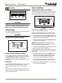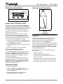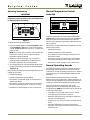
1
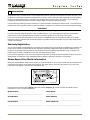
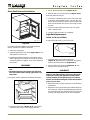
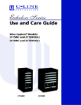
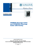
Use and Care Guide
Refrigerator Models:
1115R, 1175R, 29R
Beverage Center Model:
1175BEV
29R
1115R
1175BEV
1175R
1 Introduction
Congratulations on your purchase of a U-Line refrigeration product. A pioneer in the field for more than 40 years, U-Line
Corporation is the world’s number one manufacturer of built-in, under-counter, specialty refrigeration and ice making
products. U-Line dedicates 100% of its research and development to these products. The result: U-Line technology
consistently leads the market with innovation, design, depth of product line and performance.
U-Line products are making life more convenient in homes, businesses, and hotels around the world. U-Line supports its
products with a strong dealer network, and its commitment to quality even extends to environmentally safe packaging.
IMPORTANT
READ all of the instructions in this guide completely before operating the unit for the first time.
For future reference, keep this guide in a safe, accessible location. If you need additional information or assistance,
please contact U-Line Corporation directly. Contact information appears on the rear cover of this guide.
If you have a problem with the operation of this product, the SERVICE section of this guide will assist you in quickly
identifying common problems and provide information on possible causes and remedies. If your product needs service,
contact U-Line directly.
Warranty Registration
Your U-Line Corporation Limited Warranty is located on the inside rear cover of this guide. To validate your warranty, the
product and its original purchase date must be registered. A Warranty Registration Card has been included for this
purpose in the package containing this manual. Complete and mail the Warranty Registration Card, or register your
product online at www.U-LineService.com as soon as possible after purchase.
If your product registration is not on file and a request for warranty coverage is received, the date of sale to the U-Line
Selling Dealer or Distributor will be established as the first date of warranty coverage for your product.
Please Record Your Model Information
When you request additional information or service, you will be asked for your products model and serial numbers. You
can find this information on the serial plate located on the upper right or rear wall in the interior of your unit. This
information also appears on the warranty registration card.
2
1
ULIN_0023_A
Figure 1
Please record the model number (Figure 1, 1), serial number (Figure 1, 2), date of purchase, and dealer contact
information for your U-Line product below:
Model Number:
Dealer Name:
_____________________________________________________
_____________________________________________________
Serial Number:
Dealer Address:
_____________________________________________________
_____________________________________________________
Purchase Date:
Dealer Telephone:
_____________________________________________________
_____________________________________________________
2
1115R, 1175R, 29R, 1175BEV
2 Table of Contents
Introduction ...............................................................................................................................2
Warranty Registration .......................................................................................................2
Please Record Your Model Information ...........................................................................2
Table of Contents .......................................................................................................................3
Safety Precautions ......................................................................................................................5
Safety Alert Definitions .....................................................................................................5
General Precautions ...........................................................................................................5
Product Features ........................................................................................................................6
Origins Refrigerator Models 1115R, 1175R, 29R ..............................................................6
Origins Beverage Center Model 1175BEV ........................................................................6
Operation ...................................................................................................................................7
Initial Startup .....................................................................................................................7
Interior Lighting .................................................................................................................7
Electronic Control Panel ....................................................................................................8
Manual Temperature Control ...........................................................................................9
Normal Operating Sounds .................................................................................................9
Wine Stocking Recommendations ..................................................................................10
Outdoor, Marine and RV Usage ......................................................................................10
Storage, Vacation, Moving ..............................................................................................10
Product Disposal ...............................................................................................................10
Wine Guide ...............................................................................................................................11
Wine Recommendations ..................................................................................................11
Cleaning and Maintenance .....................................................................................................13
General Cleaning .............................................................................................................13
Maintenance ....................................................................................................................13
Service .......................................................................................................................................24
Before Calling for Service ................................................................................................24
If Service is Required ........................................................................................................24
Replacement Parts ...........................................................................................................24
Troubleshooting Guide ....................................................................................................25
Electronic Control Quick Guide .......................................................................................27
U-Line Corporation Limited Warranty ....................................................................................31
1115R, 1175R, 29R, 1175BEV
3
This page intentionally left blank
4
1115R, 1175R, 29R, 1175BEV
WARNING
3 Safety Precautions
IMPORTANT
PLEASE READ all instructions completely before
attempting to install, operate, or service your unit.
• Proper installation procedures must be followed
if this unit is being initially installed, or is moved
to a new location after being in service. An
INSTALLATION GUIDE for your unit, providing
complete installation information is available
from U-Line Corporation directly, and must be
consulted before any installation is begun. U-Line
contact information appears on the rear cover of
this guide.
• This unit requires connection to a grounded
(three-prong), polarized receptacle that has been
placed by a qualified electrician in accordance
with applicable electrical codes.
Safety Alert Definitions
Safety items throughout this guide are labeled with a
Danger, Warning or Caution based on the risk type:
DANGER
Danger means that failure to follow this safety
statement will result in severe personal injury or
death.
WARNING
Warning means that failure to follow this safety
statement could result in serious personal injury
or death.
CAUTION
Caution means that failure to follow this safety
statement may result in minor or moderate
personal injury, property or equipment damage.
General Precautions
Use this appliance for its intended purpose only and
follow these general precautions along with those listed
throughout this guide:
SHOCK HAZARD - Electrical Grounding Required.
• Never attempt to repair or perform
maintenance on the unit until the electricity
has been disconnected.
• Never remove the round grounding prong from
the plug and never use a two-prong grounding
adapter.
• Altering, cutting of power cord, removal of
power cord, removal of power plug, or direct
wiring can cause serious injury, fire and/or loss
of property and/or life, and will void the
warranty.
• Never use an extension cord to connect power
to the unit.
• Always keep your working area dry.
CAUTION
• Use care when moving and handling the unit. Use
gloves to prevent personal injury from sharp
edges.
• If your model requires defrosting, DO NOT use any
type of heater to defrost. Using a heater to speed
up defrosting can cause personal injury and
damage to the inner lining.
IMPORTANT
• Do not lift unit by door handle.
• Never install or operate the unit behind closed
doors. Be sure front grille is free of obstruction.
Obstructing free air flow can cause the unit to
malfunction and may void the warranty.
• Failure to clean the condenser every three months
can cause the unit to malfunction. This could void
the warranty.
• Allow unit temperature to stabilize for 24 hours
before use.
• If your model requires defrosting, never use an
ice pick or other sharp instrument to help speed
up defrosting. These instruments can puncture
the inner lining or damage the cooling unit.
• Use only genuine U-Line replacement parts.
Imitation parts can damage the unit, affect its
operation or performance and may void the
warranty.
DANGER
RISK OF CHILD ENTRAPMENT. Before you throw away
your old refrigerator or freezer, take off the doors
and leave shelves in place so that children may not
easily climb inside.
1115R, 1175R, 29R, 1175BEV
5
Origins Beverage Center
Model 1175BEV
4 Product Features
Origins Refrigerator
Models 1115R, 1175R, 29R
• Models 1115R and 1175R feature an electronic control
panel with digital display that allows you to display the
interior temperature and adjust the setting to your
preference. The electronic control and digital display
provide an attractive appearance and its method of
control permits precise temperature settings. Model
29R is equipped with a manual temperature control.
• In Models 1115R and 1175R, an interior light
illuminates automatically as the cabinet door is
opened. Another mode of operation is available. A
blackout/Sabbath mode (not Star K certified) allows
you to darken both interior light and the LED display,
while maintaining complete temperature control in
the unit.
• All three models qualify for the U.S. Government
ENERGY STAR program.
• All models feature maintenance-free automatic (cycle)
defrost.
• A generous capacity, one piece molded interior is very
durable and easy to clean.
• Model 1115R provides 3.3 cu ft (93 L) of refrigeration,
Model 29R provides 3.5 cu ft (99 L) of refrigeration,
and Model 1175R provides 5.7 cu ft (161 L) of
refrigeration.
• Adjustable tempered glass shelves are used. Model 29R
has two full shelves and one half shelf; Models 1115R
and 1175R have three shelves. These shelves are
designed to be easily cleaned, contain spills, and may
be positioned evenly throughout the interior to use all
space efficiently.
• Models 1115R and 1175R have two inner door “pickoff” shelves. Model 29R has fixed shelves.
• All black and white models accommodate custom flat
or raised door panels, and can achieve a custom, builtin look by matching surrounding cabinets. Please visit
www.u-line.com for additional panel information.
• Doors on black and white models are field-reversible.
Stainless steel doors are not field-reversible.
• Door locks for black and white 1175R and 29R models
are only available factory-installed at time of original
order.
• Vinyl clad steel cabinets provide a rich textured look,
and resist scratching, peeling, or flaking. Models 29R
and 1175R are available in either black or white;
Models 1115R is available in black only.
• Models 1115R and 1175R are available in stainless steel,
and feature a stainless steel door panel and hinges
with black cabinet and grille.
The Model 1175BEV Beverage Center will accommodate
up to 16 standard 750 mL bottles of your favorite wines
on its two upper, 3/4 extendable, sliding wine racks. The
Beverage Center also provides generous storage for nonwine beverages on two lower tempered shelves.
The Right Temperature for Wine
Your Beverage Center has been designed to provide two
temperature zones within the cabinet so the specific
storage requirements of your beverages can be satisfied.
The upper wine rack zone maintains an approximate
temperature of 45°F, and the lower shelf zone maintains
an approximate temperature of 38°F. NOTE: Product
temperatures, not air temperatures, are referenced above.
• An electronic control panel with digital display allows
you to display the interior temperature in the lower
shelf zone and adjust the temperature setting. The
electronic control and digital display provide an
attractive appearance, and its method of control
provides temperatures settings for a variety of wine
and non-wine beverages.
• An interior light will illuminate automatically as the
door is opened, providing easy visual identification of
the contents. You can also select two other modes of
operation:
a. The interior light can be illuminated continuously
while the door is closed for a four-hour period,
without resetting the unit, providing a visible
display of the Beverage Center contents.
b. A blackout/Sabbath mode (not Star K certified)
allows you to darken the interior lighting and the
LED display for a predetermined 36-hour period,
while maintaining complete temperature control in
the unit. This mode will self-cancel at the end of the
time period, with the lighting and LED display
returning to normal operation automatically.
• The upper chrome wine racks have a maple front trim
that adds an attractive appearance to this model. The
wood facing may be stained or replaced in its entirety
with other woods or manufactured products (such as
Corian® or Sandstone).
• The wine racks slide out, and are 3/4 extendable,
providing access to all wine bottles, including those
located on the rear portion of the rack.
• This model features maintenance-free automatic
(cycle) defrost.
• The Model 1175BEV is only available in stainless steel.
The Model 1175BEV features a stainless steel door
frame and hinges with black cabinet and grille.
• The door features a full length handle and tinted thermal
glass that protects your wines from potentially harmful
light rays while providing a very stylish appearance.
• The door is not field-reversible.
Features and specifications are subject to change without
notice.
6
1115R, 1175R, 29R, 1175BEV
Interior Lighting
5 Operation
Model 1115R, 1175R and 1175BEV
The interior of the cabinet can be illuminated whenever
the door is opened or remained darkened for a 36-hour
period (blackout/Sabbath mode [not Star K certified]).
1
2
3
4
5
ULIN_0126_A
Figure 2
IMPORTANT
Proper air flow (Figure 2) is required for your unit to
operate at its highest efficiently. A grille, located in
the base of the unit, must not be blocked at any
time, or your unit will not perform as expected.
Initial Startup
ULIN_0074_A
Figure 4
The LIGHT button (Figure 4, 1) on the control panel is
used to change the lighting functions.
All U-Line units are shipped with controls that are preset.
No initial adjustments are required.
IMPORTANT
U-Line recommends the unit be allowed to run
overnight prior to loading with product.
To turn the lights and display OFF for a preset 36-hour
interval (blackout/Sabbath mode [not Star K certified]):
1. Press and hold the LIGHT button (Figure 4, 1) for ten
seconds and release (the °F symbol will flash briefly at
the end of the ten second period).
2. The interior light and control display (Figure 4, 3) will
go dark for the next 36 hours.
1
NOTE: Although the display will not be visible, the
temperature controls in the unit remain active, and the
interior temperature will be maintained.
3. To exit the blackout/Sabbath mode (not Star K certified)
before the 36-hour period, repeat Step 1.
ULIN_0127_A
Figure 3
Models 1115R, 1175R and 1175BEV
To turn the unit ON or OFF, press and hold the ON/OFF
button (Figure 3, 1) for approximately ten seconds and
release. The display will show the unit set-point
temperature when turned ON and display OFF when the
unit is OFF.
Model 29R
To turn unit off: Turn the controller knob located in the
center of the grille counterclockwise until a “click” is
heard. It may take some force to get the control to
“click.”
Model 1175BEV has another mode of lighting available.
To illuminate the interior of the cabinet for a timed fourhour period:
1. Press and release the LIGHT button (Figure 4, 1) to
switch from door-operated lighting control to the
timed four hour lighting period (the °F symbol will
flash briefly after the LIGHT button is pressed).
2. At the end of the four-hour period, the light will turn
OFF and door-operated lighting control will resume.
3. To exit the timed lighting control before the end of the
four-hour period, repeat Step 1.
To turn unit on: Turn the controller knob located in the
center of the grille clockwise to a MID setting, number 3
or 4 on the controller knob.
1115R, 1175R, 29R, 1175BEV
7
Electronic Control Panel
1
2
3
Checking Product Temperature
4
5
ULIN_0074_A
Figure 5
Models 1115R, 1175R and 1175BEV
The electronic control with digital display (Figure 5) is
configured to show a single temperature continuously.
This set-point temperature is a base number used by the
controller to maintain the temperature zone in your unit.
The factory default set-point is 38°F. This set-point
temperature is used as a gauge if further temperature
adjustments are required.
Model 1175BEV has a DISPLAY OFF mode available
through the control panel. This mode allows you to
control whether the display (Figure 5, 3) will be ON or
OFF whenever the door is closed. The button sequence
that follows will switch between both modes:
1. Press and hold the WARMER button (Figure 5, 4), and
simultaneously within five seconds press the ON/OFF
button (Figure 5, 2) three times.
2. The display will be either visible or dark when the door
is closed.
3. To return to the previous mode, repeat Step 1.
Temperature Display Selection
U-Line products supplied for 110 VAC operation have
temperatures displayed in a default Fahrenheit (°F)
configuration (Figure 5, 3). Models supplied for 220 VAC
operation have temperatures displayed in a default
Celsius (°C) configuration.
The display can easily be adjusted for either type of
temperature display. Press and hold the LIGHT button
(Figure 5, 1) and simultaneously within five seconds
press the COOLER button (Figure 5, 5) three times to
change the display as desired.
ULIN_0093_A
Figure 6
IMPORTANT
U-Line recommends a set temperature of 38°F on all
refrigerators.
To check the actual product temperature in your unit,
insert an accurate thermometer into a plastic (nonbreakable) bottle that is partially filled with water.
Tighten the bottle cap securely (Figure 6).
Place the bottle in the desired area for 24 hours. Refrain
from opening the unit during the testing period. After 24
hours, check the temperature of the water. If required,
adjust the temperature control in a small increment (See
ADJUSTING TEMPERATURE).
Factors which affect the internal temperatures of the
cabinet include:
• Temperature setting.
• Ambient temperature where installed.
• The number of times and length of time a door is
opened and closed.
• The amount of time the internal light is illuminated.
(This affects primarily product on top rack or shelf.)
• Installation in direct sunlight or near a heat source.
Temperature Display
To display actual temperature:
1. Press the WARMER button (Figure 5, 4) for five
seconds. The display (Figure 5, 3) will indicate the
actual temperature.
2. After approximately 10 seconds, the set point
temperature will return to the display.
8
1115R, 1175R, 29R, 1175BEV
Manual Temperature Control
Adjusting Temperature
Model 29R
IMPORTANT
Adjust the set point temperature in single
increments, and wait 24 hours for the temperature
to stabilize before rechecking.
1
2
3
4
1
5
ULIN_0014_A
Figure 8
ULIN_0074_A
Figure 7
To adjust the set point temperature:
1. Press and release either the WARMER (Figure 7, 4) or
COOLER (Figure 7, 5) button to put the controller in
the SET TEMPERATURE mode. The °F (or °C) symbol will
begin to flash.
NOTE: If no further action is taken, this mode will self
cancel in five seconds, and the original set-point
temperature will be displayed.
Adjust the temperature by turning the numbered dial
(Figure 8, 1) in small increments. Turn knob clockwise to
make unit colder and counterclockwise to make unit
warmer. After adjusting temperature, allow 24 hours for
unit to stabilize.
Many factors can affect the internal temperatures of the
cabinet. They include:
• Temperature setting.
• Ambient temperature where installed.
• The number of times and length of time the door is
opened and closed.
2. Within five seconds (while the °F (or °C) symbol is
flashing), press the WARMER or COOLER button as
required to adjust the set point temperature.
• The amount of time the internal light is illuminated.
(This affects primarily product on top rack or shelf.)
3. The change will be set five seconds after adjusting the
temperature, and the new set-point will be displayed
(Figure 7, 3).
Normal Operating Sounds
Many factors can affect the internal temperatures of the
cabinet. They include:
• Temperature setting.
• Ambient temperature where installed.
• The number of times and length of time the door is
opened and closed.
• The amount of time the internal light is illuminated.
(This affects primarily product on top rack or shelf.)
• Installation in direct sunlight or near a heat source.
• Installation in direct sunlight or near a heat source.
All models incorporate rigid foam insulated cabinets to
provide high thermal efficiency and maximum sound
reduction for its internal working components. In spite of
this technology, your model may make sounds that are
unfamiliar.
Normal operating sounds may be more noticeable
because of the unit’s environment. Hard surfaces such as
cabinets, wood/vinyl/tiled floors and paneled walls have a
tendency to reflect normal appliance operating noises.
Common refrigeration components, and a brief
description of the normal operating sounds they make,
are listed below. NOTE: Your product may not contain all
of the components listed.
• Compressor: The compressor makes a hum or pulsing
sound that may be heard when it operates.
• Evaporator: Refrigerant flowing through an evaporator
may sound like boiling liquid.
• Condenser Fan: Air moving through a condenser may be
heard.
• Automatic Defrost/Drain Pan: Water may be heard
dripping or running into the drain pan when the unit is in
the defrost cycle.
1115R, 1175R, 29R, 1175BEV
9
Wine Stocking Recommendations
Storage, Vacation, Moving
Model 1175BEV
If the unit will not be used for an extended period, or
otherwise stored, follow these steps completely:
Specially designed wine racks allow for the proper
horizontal storage of wine. The bottles are properly
positioned so the wine remains in contact with the cork to
assure that the cork does not become dry.
The wine racks should be stocked staggering the bottles
as shown (Figure 9).
WARNING
Electrical Shock Hazard. Disconnect power before
servicing. Before operating, replace all panels.
Failure to do so may result in death or electrical
shock.
1. Remove all consumable contents from the unit.
2. Disconnect the power cord from its outlet, and leave it
disconnected until the unit is returned to service.
3. Clean and dry the interior of the cabinet (See CLEANING
AND MAINTENANCE: GENERAL CLEANING).
ULIN_0019_A
Figure 9
Outdoor, Marine and RV Usage
Some U-Line models are designed to operate in outdoor,
marine and RV environments. For best performance, keep
the unit out of direct sunlight.
• If the unit will be shut off for five days or more, prop
door open to allow for air circulation and prevent mold
and mildew.
4. During periods of non-use, the cabinet must remain
open to prevent the formation of mold and mildew.
Open door a minimum of 2 in. (5 cm) to provide the
necessary ventilation.
Product Disposal
If the unit is being removed from service for disposal,
check and obey all Federal, State and/or Local regulations
regarding the disposal and recycling of refrigeration
appliances, and follow these steps completely:
1. Remove all consumable contents from the unit.
2. Disconnect power to the unit and unplug the power
cord from its outlet.
IMPORTANT
If the ambient temperature is expected to drop
below 45°F, turn off and unplug unit, and drain all
water from the unit to prevent freezing damage not
covered by the warranty.
• High ambient temperatures (110°F or higher) may
reduce the unit's ability to reach low temperatures.
10
DANGER
RISK OF CHILD ENTRAPEMENT. Before you throw
away your old refrigerator or freezer, take off the
doors and leave shelves in place so that children
may not easily climb inside.
3. Remove the cabinet door.
1115R, 1175R, 29R, 1175BEV
Suggestions for Matching Food and Wine
6 Wine Guide
Wine Recommendations
To most, wine is a delicious mystery. We purchase it,
uncork it, and savor its taste and beauty. But there is so
much more to true wine appreciation. Many secrets are
simply too good to keep bottled up. The U-Line
Corporation is proud to present Spilling Wine Secrets
online at www.U-Line.com/resources/wine_secrets. Take a
moment to explore this section of our website to uncover
wine myths, learn ideal storage conditions or ask our wine
expert, Mr. Dave Barna, a specific question relating to
wine. Mr. Barna will respond to your inquiry, and it may
also be selected to appear on our Questions and Answers
page.
Wine Selections Suggestions
Selecting the right wine for the right occasion can
sometimes be a seemingly awkward or difficult task for
the beginning wine enthusiast. We would therefore like
to present you with a few suggestions which may provide
a little more confidence and enjoyment when choosing
and serving your wines.
When selecting wines, keep an open mind and do not be
afraid to be adventurous. Do not view the subject of wine
so seriously it discourages you from learning and
discovering for fear of embarrassment if something is
incorrect. Wine is best viewed as a hobby and enjoyed.
When assembling your collection, try not to become
obsessed with “Vintages.” Although a chart can be a
useful tool, generalizations about a specific year have led
more than one collector to disappointment. In many
instances an “Off Year” will provide a better value and
more drinking enjoyment.
Although there are no hard fast rules for matching wine
to food, observe some guidelines. Delicate dishes should
be accompanied by lighter more delicate wines. Fullflavored foods should be matched with fuller-bodied
wines.
As a general rule, one should aim to ascend in flavor and
quality of wines served.
Table 1
Serve a:
Before a:
DRY wine
SWEET wine
WHITE wine
RED wine
YOUNG wine
OLD wine
LIGHT-BODIED wine
FULL-BODIED wine
Any step back in quality will be noticed. If a fine wine is
tasted prior to a lesser wine, many of the fine wine’s
subtle qualities may be missed.
Common Food and Wine Matches
Table 2
Foods
Wines
Fish, Shell Fish, Crab, Oysters
Dry White Wines, Light
Sparkling or Extra Dry
Champagne
Beef, Venison
Full-Bodied Red Wines
Pork, Veal, Lamb and Poultry
Light-Bodied Red Wines
Fruit
Sweet White and Sparkling
Wines
The primary guideline to the subject of wine is your own
palate. Do not be afraid to make mistakes. Experiment,
discover, but most of all, enjoy yourself and your new
U-Line product.
1115R, 1175R, 29R, 1175BEV
11
Guide to Common Styles of Wine
Red Wines
Full-Bodied Dry
California
French
Italian
Zinfandel, Cabernet
Rhone, Chateauneuf-du-Pape
Barbaresco, Barolo
Medium-Bodied Dry
California
French
Pinot Noir
Bordeaux, Burgundy
Light-Bodied Dry
French
Italian
Beaujolais
Chianti, Bardolino
Full-Bodied Dry
California
French
Chardonnay
Montrachet, Meursault
Puligny-Montrachet
Medium-Bodied Dry
California
French
Sauvignon-Blanc
Pouilly-Fuisse, Sancerre,
Vouvray, Graves
Light-Bodied Dry
French
Chablis, Muscadet, Pouilly-Fume
Full-Bodied, Very Sweet
Germany
Frency
Hungary
Beerenauslese
Sauternes
Tokay
Medium-Bodied, Semi-Sweet
California
Germany
Gewurtztraminer
Liebfraumilch
Light-Bodied Off Dry
Germany
Rhine, Mosel, Riesling
White Wines
Common Tasting Terms
Terminology
Description
Acidity
A critical element of wine that is responsible for preserving the wines freshness. Excess acidity results in an
overly tart and sour wine.
Balance
A desired trait where tannin, fruit and acidity are in total harmony. Wines with good balance tend to age
gracefully.
Body
The weight and presence of wine in the mouth provided by the alcohol and tannin level. Full-bodied wines
tend to have this strong concentration.
Bouquet
The blending of a wine's aroma within the bottle over a period of time, caused by volatile acidity.
Complex
A subjective term often used in tasting. A wine is said to be complex if it offers a variety of flavors and scents
that continue to evolve as it develops.
Flabby
A wine that lacks structure, or is heavy to the taste, lacks acidity.
Full-Bodied
Wine high in alcohol and extract, generally speaking, fills the mouth, powerful.
Lean
Generally describes wines that are slim, lacking of generosity or thin.
Oaky
A desirable flavor imparted to wine if done in moderation. Most wines are aged in oak barrels one to three
years, thereby receiving this toasty oak characteristic. However, if a weak wine is left in contact too long with
an oak barrel it will tend to be overpowered with an oaky taste.
Tannin
Tannins are extracted from the grape skins and stems and are necessary for a well-balanced red wine. Tannins
are easily identified in wine tasting as the drying sensation over the gums. Tannins generally fade as a wine
ages.
12
1115R, 1175R, 29R, 1175BEV
7 Cleaning and Maintenance
General Cleaning
• Do not use any solvent-based or abrasive
cleaners. These types of cleaners may transmit
taste to the interior products and damage or
discolor the interior.
Maintenance
Exterior Cleaning (As Required)
Vinyl Clad (Black or White) Models:
• Surfaces may be cleaned with a mild detergent and
warm water solution. Do not use solvent-based or
abrasive cleaners. Use a soft sponge and rinse with
clean water. Wipe with a soft, clean towel to prevent
water spotting.
• Clean any glass surfaces with a non-chlorine glass
cleaner.
Stainless Models:
• Stainless door panels, handles and frames can discolor
when exposed to chlorine gas, pool chemicals, salt
water or cleaners with bleach.
• Keep your stainless unit looking new by cleaning with
a good quality all-in-one stainless steel cleaner/polish
on a monthly basis. For best results use Claire® Stainless
Steel Polish and Cleaner, which can be purchased from
U-Line Corporation (P/N 173348). Comparable products
are acceptable. Frequent cleaning will remove surface
contamination that could lead to rust. Some
installations may require cleaning on a weekly basis.
Proper maintenance of your U-Line product will ensure
efficiency, top performance and long life. The
maintenance intervals listed are based on normal
conditions. You may want to shorten the intervals if you
have pets or other special considerations.
Defrosting
Automatic (Cycle) Defrost Models
Automatic defrost models do not produce frost in normal
operating conditions. However, a frost pattern may be
noticed on the interior walls if the unit is repeatedly
opened in a high heat or high humidity location. If this
frost pattern does not clear within 24 hours, your unit will
require manual defrosting.
WARNING
DO NOT use any type of electrical heating device,
ice pick, knife or other sharp instrument to
defrost; this could damage the inner lining or
refrigeration system and void the warranty.
IMPORTANT
• Do not clean with steel wool pads.
• Do not use stainless steel cleaners/polishes on
any glass surfaces.
• Clean any glass surfaces with a non-chlorine glass
cleaner.
• Do not use cleaners that are not specifically
intended for stainless steel on stainless surfaces
(this includes glass, tile and counter cleaners).
The drain pan was not designed to capture the
water created when manually defrosting. To
prevent water from overflowing the drain pan,
place towels or other absorbent materials over the
interior drain trough, under the evaporator (Figure
10, 1), before defrosting.
• If any surface discoloring or rusting appears, clean it
quickly with Bon-Ami® or Barkeepers Friend Cleanser®
and a non-abrasive cloth. Always clean in the direction
of the grain. Always finish this process with Claire
Stainless Steel Polish and Cleaner or comparable
product to prevent further problems.
1
• Using abrasive pads such as Scotchbrite™ will
cause the graining in the stainless to become
blurred.
• Rust that is not cleaned up promptly can penetrate into
the surface of the stainless steel and complete removal
of the rust may not be possible.
Interior Cleaning (As Required)
• Disconnect power to the unit. Clean the interior and all
removed components using a mild non-abrasive
detergent and warm water solution applied with a soft
sponge or non-abrasive cloth. Rinse the interior using a
soft sponge and clean water.
ULIN_0196_A
Figure 10
1115R, 1175R, 29R, 1175BEV
13
To defrost:
4. Remove grille and grille cap from unit.
1. Turn unit off.
1
2. Remove all products from the interior and prop the
door in an open position (2 in. (5 cm) minimum).
3. Allow the frost to completely melt naturally. Clean the
interior and all removed components using a mild nonabrasive detergent and warm water solution applied
with a soft sponge or non-abrasive cloth. NOTE: DO
NOT use any solvent-based or abrasive cleaners. They
will discolor or damage the interior.
4. Dampen a soft sponge or non-abrasive cloth in clean
water and wipe down the cabinet interior and removed
components to remove any detergent residue. Rinse the
sponge or cloth in clean water and repeat as necessary
until the cabinet and components are clean.
ULIN_0153_A
Figure 12
5. Clean the condenser coil (Figure 12, 1) using a using a
soft brush with a “combing” action or vacuum cleaner.
Do not touch the condenser coil.
5. When the interior is dry, turn unit on.
Condenser Cleaning
Interval - Every Three Months
To maintain operational efficiency, keep the front grille
free of dust and lint, and clean the condenser every three
months. Depending on environmental conditions, more
or less frequent cleaning may be necessary.
2
1
ULIN_0198_A
Figure 13
WARNING
Disconnect electric power to the unit before
cleaning the condenser.
WARNING
6. Make sure grille cap is behind grille in slots provided in
grille (Figure 13, 1) before attaching grille to unit, and
secure but do not overtighten both grille screws
(Figure 13, 2).
7. Reinstall the control knob (Figure 11, 1).
DO NOT touch the condenser fins. The condenser
fins are SHARP and can be easily damaged.
8. Reconnect power to the unit.
Model 1115R
IMPORTANT
1. Disconnect power to the unit.
DO NOT use any type of cleaner on the condenser
unit.
1
Model 29R
1. Disconnect power to the unit.
3
2
2
ULIN_0155_A
Figure 14
2. Loosen the two screws (Figure 14, 1) completely.
1
ULIN_0197_A
Figure 11
2. Remove the control knob (Figure 11, 1) by pulling it
straight out, away from grille.
NOTE: Screws are held in the grille by o-ring retainers,
and will not come free of the grille.
3. Remove grille (Figure 14, 2) and grille cap (Figure
14, 3) from unit.
3. Remove two screws from grille (Figure 11, 2) and save.
14
1115R, 1175R, 29R, 1175BEV
1
1
2
ULIN_0156_A
Figure 15
3
4. Clean the condenser coil (Figure 15, 1) using a using a
soft brush with a “combing” action or vacuum cleaner.
Do not touch the condenser coil.
ULIN_0159_A
Figure 18
5. Place the hook-hinge (Figure 18, 1) located on the
rear bottom side of the grille onto the front lip (Figure
18, 2) of the unit base. Swing the grille up into
position, and align the screw holes on the grille to the
grille screw hole on the cabinet.
6. Secure, but do not overtighten both grille screws
(Figure 18, 3).
7. Reconnect power to unit.
1
2
Leveling
3
ULIN_0157_A
Figure 16
5. Make sure grille cap (Figure 16, 1) is behind grille in
slots (Figure 16, 2) provided in grille before attaching
grille to unit, and secure, but do not overtighten both
grille screws (Figure 16, 3).
It is important that units equipped with adjustable feet
are level, for proper door and ice maker (if equipped)
operation.
NOTE: Models 29R DO NOT have leveling feet. These
models MUST be placed on a level surface to operate
properly.
To level units with adjustable feet:
6. Reconnect power to the unit.
Models 1175R and 1175BEV
1. Disconnect power to unit.
1
2
1
ULIN_0158_A
ULIN_0041_A
Figure 17
Figure 19
2. Loosen the two screws (Figure 17, 1) completely.
NOTE: Screws are held in the grille by o-ring retainers,
and will not come free of the grille.
1. Use a level to check the levelness of the unit from
front to back and from side to side. Level should be
placed along top edge and side edge as shown
(Figure 19).
3. Remove grille from unit.
4. Clean the condenser coil (Figure 17, 2) using a using a
soft brush with a “combing” action or vacuum cleaner.
Do not touch the condenser coil.
1115R, 1175R, 29R, 1175BEV
15
Door Reversal
Black or white unit doors may be left- or right-hand
opening. Depending upon the location of the unit, it may
be desirable to change the side on which the door is
mounted.
Black Model 1115R
To reverse the door, perform the following:
1
ULIN_0042_A
1. Remove the grille and grille cap (two screws).
Figure 20
2. If the unit is not level, adjust the feet on the corners of
the unit as necessary (Figure 20).
3. Check the levelness after each adjustment and repeat
the previous steps until the unit is level.
Door Alignment Check and Adjustment
IMPORTANT
Properly aligned, the door’s gasket should be firmly
in contact with the cabinet all the way around the
door (no gaps). Carefully examine the door’s gasket
to assure that it is firmly in contact with the
cabinet. Also make sure the door gasket is not
pinched on the hinge side of the door.
ULIN_0143_A
Figure 22
2. Remove top hinge from cabinet (three screws) (Figure
22). Hold door to keep it from falling.
3. Lift the door off the bottom hinge.
ULIN_0143_A
Figure 21
NOTE: Model 29R shown (Figure 21)
1. Loosen (do not remove) top (Figure 21) and bottom
hinge screws.
ULIN_0121_A
2. Align door squarely with cabinet.
3. Make sure gasket is firmly in contact with cabinet all
the way around the door (no gaps).
4. Tighten bottom hinge screws.
Figure 23
4. Remove bottom hinge from cabinet (two screws)
(Figure 23).
5. Tighten top hinge screws.
16
1115R, 1175R, 29R, 1175BEV
7. Relocate plastic spacer/bushing (Figure 26) on bottom
of door to opposite side, and place door on bottom
hinge pin. Clean out bushing hole in door bottom with
a screwdriver if necessary.
Hinge
Plastic
Plug Hole
Plastic
Plug Hole
Screw
Right Side
Door Swing
Left Side
Door Swing
Right Side
Hinge
ULIN_0122_A
Invert
Screw
Invert
Hinge
ULIN_0142_A
Figure 24
Figure 27
5. Remove screws on opposite side of cabinet (Figure 24).
Note that there may be a nut behind one or both
screws on either side.
8. Remove plastic hole plug (Figure 27) from door handle
and relocate on opposite side.
9. Remove pivot screw from top hinge, invert screw and
reinstall pivot screw in top hinge. See Figure 30.
ULIN_0144_A
ULIN_0123_A
Figure 28
Figure 25
6. Install hinge on opposite side, bottom of cabinet
(Figure 25). Replace nut on back side where installed.
Align hinge outer edge with cabinet before tightening
screws.
10. Remove three plastic screw plugs (Figure 28) from
hinge holes, top of cabinet, opposite side. Be careful
not to scratch cabinet.
11. Place door on lower hinge pin. Invert and install upper
hinge on door.
1
ULIN_0109_A
ULIN_0145_A
Figure 26
Figure 29
1115R, 1175R, 29R, 1175BEV
17
12. Fasten upper hinge to unit (three screws) (Figure 29).
Partially tighten screws.
13. Adjust door to assure proper seal. Tighten upper and
lower hinge screws securely.
Hinge
Plastic
Plug Hole
Plastic
Plug Hole
14. Replace three plastic plugs removed in Step 10 into
holes on top of unit. Replace screws in holes in bottom
of unit on opposite side.
15. Replace the grille and grille cap. Be sure to place grille
cap on opposite side of unit from where it was
originally.
Screw
Right Side
Door Swing
Left Side
Door Swing
Right Side
Hinge
Invert
Screw
Invert
Hinge
ULIN_0106_A
Black or White Model 1175R
Figure 32
To reverse the door, perform the following:
5. Remove pivot screw from top hinge, invert screw and
reinstall pivot screw in top hinge (Figure 32). Do not
install hinge on cabinet at this time.
1. Remove the grille (two screws).
ULIN_0104_A
ULIN_0107_A
Figure 30
Figure 33
2. Remove top hinge from cabinet (four screws) (Figure
30). Hold door to keep it from falling.
6. Remove bottom hinge from cabinet (four screws) and
screws on opposite side of cabinet (Figure 33).
3. Lift the door off the bottom hinge.
7. Remove pivot screw from bottom hinge, invert screw
and reinstall pivot screw in hinge (Figure 32).
ULIN_0160_A
ULIN_0105_A
Figure 31
Figure 34
4. Remove four plastic plugs (Figure 31) in hinge holes,
top of cabinet, opposite side. Be careful not to scratch
cabinet.
18
8. Install bottom hinge on cabinet, opposite side, aligning
flat edge of hinge with outer edge of unit (Figure 34).
Partially tighten screws.
1115R, 1175R, 29R, 1175BEV
2. Remove two screws from grille (Figure 37, 2) and save.
3. Remove the grille and grille cap from unit.
1
ULIN_0109_A
Figure 35
9. Relocate plastic spacer/bushing (Figure 35) on bottom
of door to the opposite side. Clean out bushing hole in
door bottom if necessary.
ULIN_0143_A
Figure 38
4. Remove top hinge from cabinet (three screws) (Figure
38). Hold door to keep it from falling.
5. Lift the door off the bottom hinge.
ULIN_0110_A
Figure 36
10. Place door on lower hinge pin. Align flat edge of top
hinge with outer edge of unit and fasten upper hinge
to unit (four screws) (Figure 36). Partially tighten
screws until door is aligned.
11. Adjust door to assure proper seal. Tighten upper and
lower hinge screws securely.
12. Replace four plastic plugs removed in Step 4 into holes
on top of unit. Replace screws in holes in bottom of unit
on opposite side.
ULIN_0121_A
Figure 39
13. Replace the grille.
6. Remove bottom hinge from cabinet (two screws)
(Figure 39).
Model 29R
To reverse the door, perform the following:
2
1
ULIN_0197_A
Figure 37
1. Remove the control knob (Figure 37, 1) by pulling it
straight out, away from grille.
1115R, 1175R, 29R, 1175BEV
19
9. Relocate plastic spacer/bushing (Figure 42, 1) on
bottom of door to opposite side, and place door on
bottom hinge pin. Clean out bushing hole in door
bottom with a screwdriver if needed.
Hinge
Plastic
Plug Hole
Plastic
Plug Hole
Screw
Right Side
Door Swing
Left Side
Door Swing
Right Side
Hinge
ULIN_0122_A
Invert
Screw
Invert
Hinge
ULIN_0142_A
Figure 40
Figure 43
7. Remove screws on opposite side of cabinet (Figure 40).
Note that there may be a nut behind one or both
screws on either side.
10. Remove plastic hole plug from door handle and
relocate on opposite side (Figure 43).
11. Remove pivot screw from top hinge, invert screw and
reinstall pivot screw in top hinge (Figure 43).
ULIN_0144_A
ULIN_0123_A
Figure 44
Figure 41
8. Install hinge on opposite side, bottom of cabinet
(Figure 41). Replace nut on back side where installed.
Align hinge outer edge with cabinet before tightening
screws.
12. Remove three plastic screw plugs (Figure 44) in hinge
holes, top of cabinet, opposite side. Be careful not to
scratch cabinet.
13. Place door on lower hinge pin. Invert and install upper
hinge on door.
1
ULIN_0109_A
Figure 42
20
1115R, 1175R, 29R, 1175BEV
Door Shelf Removal/Insertion
1
2
ULIN_0143_A
Figure 45
ULIN_0040_A
14. Fasten upper hinge to unit (three screws) (Figure 45).
Partially tighten screws until door is aligned.
Figure 47
15. Adjust door to assure proper seal. Tighten upper hinge
screws securely.
NOTE: 1115R and 1175R models only
16. Replace three plastic plugs removed in Step 11 into
holes on top of unit. Replace screws in holes in bottom
of unit, opposite side.
1. Grasp shelf in center, and lift until the shelf notches
(Figure 47, 1) clear the bosses (Figure 47, 2).
17. Re-inspect door seal and alignment. Adjust if needed.
To remove the door shelf:
2. Carefully pull the shelf away from the door.
To install the door shelf:
1. Holding the shelf in the center, center the shelf in the
door at the desired location, slightly above the bosses
(Figure 47, 2).
2. Lower the shelf onto the bosses (Figure 47, 2).
2
1
ULIN_0198_A
Figure 46
18. Make sure grille cap is behind grille in slots provided in
grille (Figure 46, 1) before attaching grille to unit, and
secure but do not overtighten both grille screws
(Figure 46, 2).
1115R, 1175R, 29R, 1175BEV
21
Glass Shelf Removal/Installation
2. Tilt up right-hand edge of shelf (Figure 49, 2).
3. Remove shelf from unit by pulling out (Figure 49, 3).
Insert the shelves as follows:
1. To move to a different position in the unit, insert shelf
at an angle, approximately 15-20°, over the rib in the
side of the unit where you want to place the shelf. The
shelf must be started into the unit at an angle to clear
the door.
2. Continue to slide the shelf into the unit at an angle
until it clears the door.
1
3. Lower the shelf and push it in completely.
Light Bulb Replacement
1115R, 1175R and 1175BEV
ULIN_0199_A
To replace the light bulb in your U-Line unit:
Figure 48
For Models 29R and 1175BEV (Model 29R illustrated
above), reposition the shelves as follows:
1
2
1. Open door completely.
2. Grasp the shelf edge in the center (Figure 48, 1), and
slide the shelf from the unit.
3. Reposition the shelf as required, ensuring the raised
white edge strip is toward the rear of the unit and the
decorative graphics, if applied, are on the underside of
the shelves.
IMPORTANT
• Make sure the shelves are inserted fully into the
unit.
• The white edge strip toward the rear prevents
cans and bottles from freezing against the cold
evaporator.
For all other models, reposition the shelves as follows:
ULIN_0001_A
Figure 50
1. Grasp the edges of the light housing lens
(Figure 50, 1) opposite the exposed tab, and gently
push the lens towards the tab (Figure 50, 2).
2. Pull the edge of the lens down (Figure 50, 1), and
swing it out of the light housing.
IMPORTANT
ALWAYS use a genuine U-Line replacement bulb (P/N
31317) in the light housing. Use of any other bulb
within the housing will generate excessive heat,
causing damage to the light housing and cabinet
interior, and compromising the precise temperature
control of your unit.
3. Replace the bulb only with a genuine U-Line P/N 31317
replacement.
3
4. Replace the lens by first inserting the tab side back into
the housing at a slight angle. While gently pushing the
lens towards the tab end, push the free end up into the
housing, and release when you will hear a snap/click.
1
2
ULIN_0066_A
Figure 49
1. Pull shelf out about 6" (Figure 49, 1), until back of
shelf clears the “hump” on the right-hand side.
22
1115R, 1175R, 29R, 1175BEV
Wine Rack Removal/Installation
Wood Trim Finishing
1175BEV
Interior components of your U-Line unit are equipped
with a natural wood trim for appearance and durability.
Although this wood trim has been coated with a clear
sealer at the factory, it is recommended that the trim be
stained (if desired), and receive a final finish coating prior
to the unit going into full-time service.
To remove a rack from the cabinet:
1. Grasp the end of the rack, and gently slide it out until
it stops.
2. Remove any bottles stored on the rack.
WARNING
To prevent permanent damage to the inner liner
of your unit, the wood trim MUST be removed
from the unit for staining and/or finishing. Allow
stain/finish to dry thoroughly (at least 24 hours
per coat) in accordance with the product
manufacturer’s instructions prior to
reinstallation. Failure to do so may cause the
inner liner of the unit to have a permanent odor,
which is not covered by the warranty.
ULIN_0162_A
Figure 51
3. Press the left rack release lever (Figure 51) down, and
at the same time, lift the corresponding right rack
release lever up, and pull the rack out until it is free of
the tracks and the cabinet.
If staining the trim is desired, it must be done before the
application of any type of final finish. Review the
following staining/final finish and final finish-only
guidelines when staining/ and or sealing the wood to
ensure proper adhesion and durability of the finish.
NOTE: Glass in door is tinted. Stain may look darker
when door is closed.
Staining and final finish application:
IMPORTANT
Do not remove the track side rails from the cabinet.
To insert a rack in the cabinet:
1. Align the left and right rack channels with the tracks
in the cabinet, and ensuring an even track
engagement on both sides, gently push the rack into
the cabinet until it stops.
2. Before reloading the rack, ensure proper operation of
the travel stops in the left and right track rails by
pulling the rack out gently until it completely stops.
1. Remove all screws securing wood trim to interior
components, and remove the trim from the cabinet
interior.
NOTE: Your model may contain an electronic display
panel in the lowest level trim piece. After removing the
trim screws, and gently pulling the trim from its location,
a wiring harness connector will become visible. Unplug
the connector, and remove the trim from the interior.
IMPORTANT
DO NOT use oil-based stains on wood trim. Vapors
from oil-based stains will permanently penetrate
the liner and will not dissipate over time.
2. Apply Minwax® Water-Based Wood Stain to wood with
a synthetic bristle brush or a foam applicator. Allow
stain to penetrate approximately three minutes. Before
the stain is dry, take a stain dampened rag and remove
any excess stain remaining. Wipe in the direction of the
grain with medium pressure to achieve the desired stain
color.
3. After two hours, repeat step 2. This will even out the
color of the wood.
4. Allow stain to dry for a minimum of three hours before
applying the final finish.
5. If desired, sand the wood with very fine sandpaper to
smooth the surface after the staining process.
1115R, 1175R, 29R, 1175BEV
23
6. Remove all dust from the wood, and apply one coat of
Minwax® Polycrylic® Protective Finish using a synthetic
bristle brush to the wood. This finish should be applied
in a thin coat following the direction of the grain.
Apply the finish to the back and sides of the wood first,
and allow it to dry for two hours. Apply the finish to the
front side of the wood next, and allow it to dry for two
hours. Sand with very fine 220 grit sandpaper. Apply
two addition coats of the finish in the same manner, but
do not sand the trim after the final third coat is applied.
7. Allow the final coat to dry for 24 hours before
reinstalling the trim to the cabinet interior components.
Final finish-only application:
1. Remove all screws securing wood trim to interior
components, and remove the trim.
2. Lightly scruff sand the wood trim with 280 or finer grit
sandpaper.
3. Remove sanding dust with a clean, dry cloth.
4. The factory-applied seal is compatible with virtually all
finishes. A low odor, water clean up, quick-drying finish
such as Minwax® Polycrylic® Protective Finish is
recommended (Minwax® Polycrylic® is an ultra fastdrying water-based finish). Apply a thin coat of a clear,
protective finish, following the container label
directions.
5. Lightly sand and reapply if desired.
6. Allow the final coat to dry for 24 hours before
reinstalling the trim to the cabinet interior components.
24
8 Service
Before Calling for Service
If your U-Line product appears to be malfunctioning, read
through the OPERATION section of this guide to ensure
that the function of all controls are clearly understood. If
the malfunction persists, the TROUBLESHOOTING GUIDE
in this guide will assist you in quickly identifying common
problems, and provide information on possible causes and
remedies. Most often, this will resolve the problem
without the need to call for service.
If Service is Required
If you do not understand a troubleshooting remedy, or
your product needs service, contact U-Line Corporation
directly. Contact information appears on the rear cover of
this guide.
You will be asked for your product Model and Serial
Numbers. This information should be recorded inside the
front cover of this guide, following the products original
purchase. It also appears on the Model and Serial number
plate located on the upper right or rear wall of the
interior of your product.
Replacement Parts
When you need replacement parts, always request that
genuine U-Line replacements be used. U-Line products
have been designed and engineered using components
that work efficiently, and provide superior service life and
performance. The use of aftermarket parts or components
may affect the safety, operation, performance or
durability of your product, and may also void its warranty.
1115R, 1175R, 29R, 1175BEV
Troubleshooting Guide
NOTE: Recommended temperature setting is 38°.
DANGER
ELECTROCUTION HAZARD
Never attempt to repair or perform maintenance on
the unit until the main electrical power has been
disconnected.
Troubleshooting - What to check when problems occur:
PROBLEM
POSSIBLE CAUSE
REMEDY
Unit does not operate and
electronic display is blank.
No electrical supply
Plug unit in or check circuit breaker.
No interior light
Loose or burned out bulb
Tighten or replace bulb (See MAINTENANCE; LIGHT
BULB REPLACEMENT).
Light won't go out when door is
closed (Model 1175BEV).
Light on/off switch is turned to ON.
Turn switch to OFF (See OPERATION).
Unit not cold enough
Light staying on
Adjust door (See MAINTENANCE; DOOR ALIGNMENT
CHECK AND ADJUSTMENT).
Door gasket not sealing properly
Adjust door (See MAINTENANCE; DOOR ALIGNMENT
CHECK AND ADJUSTMENT).
Item(s) interfering with door
Reposition or remove item(s).
Dirty condenser coils
Clean condenser (See MAINTENANCE; CONDENSER
CLEANING).
Airflow to front grille blocked
Airflow must not be obstructed to front grille (See
OPERATION).
High ambient temperature or
exposure to direct sunlight
Reposition unit.
Temperature not set cold enough
Set control to a cooler setting (See OPERATION). Allow
24 hours for temperature to stabilize.
Door gasket not sealing properly.
Door left open
Adjust door (See MAINTENANCE; DOOR ALIGNMENT
CHECK AND ADJUSTMENT).
High ambient temperatures or
humidity
Defrost unit manually (See MAINTENANCE;
DEFROSTING).
Certain sounds are normal.
Soft sounds from the fan and water/dropping sounds
from the ice maker will be heard.
Fan blade touching obstruction
(wiring, foam insulation, etc.)
Remove obstruction.
The unit frosts up.
Noise during operation
Unit too cold
Temperature control set too cold
Set control to warmer setting (See OPERATION).
Freezing product
Product touching evaporator in back
of unit
Move product away from evaporator, making sure it is
not touching evaporator.
1115R, 1175R, 29R, 1175BEV
25
Troubleshooting - Models with an electronic display:
PROBLEM
POSSIBLE CAUSE
REMEDY
Electronic display is blank and
interior light is off with door open.
Unit is in blackout/Sabbath mode
(not Star K certified).
Exit blackout/Sabbath mode (not Star K certified)
(See OPERATION).
Electronic display is blank and
interior light is on with door open.
A display function has changed.
Touch and hold the WARMER button and touch and
release the ON/OFF button three times, then release the
temperature button. The display should become visible.
Electronic display shows repeating,
randomly flashing symbols and
partial characters.
A factory control mode has been
inadvertently entered.
Touch and hold the warmer temperature button and
touch and release the LIGHT button three times, then
release the temperature button to exit the factory
control mode. The set-point temperature should now
be displayed.
Electronic display shows:
0, 1 to 16, or 99.
A factory control mode has been
inadvertently entered.
Repeatedly touch the WARMER button to advance any
number shown to 99 and touch and release the LIGHT
button. The set-point temperature should now be
displayed.
Electronic display shows one or
more of the following:
E1, E2, E4, E5, E6.
The unit is displaying an error code.
Record the error code(s) displayed and call for service.
26
1115R, 1175R, 29R, 1175BEV
Electronic Control Quick Guide
Task
Turn ON/OFF
Adjust
Temperature
Touch
ON/
OFF
WARMER
Hold 10 seconds
or
COOLER
Touch and release
View Actual
Temp
WARMER
Change F/C
Hold 5 seconds
Hold
Blackout
Mode
Touch
Display
Release when °F flashes.
or
WARMER
or
°F flashes after first
touch, set-point saved
after 5 seconds of
inactivity and °F stops
flashing.
COOLER
Touch to change temperature
WC models will scroll
top/mid/bottom temps.
Release when °F flashes.
COOLER
COOLER
or
COOLER
Display (and cabinet light) will not
operate in Blackout Mode.
Hold 10 seconds
Comment
Blackout will end in 36
hours, or hold again to
terminate early.
Glass Door Models Only
Light normally goes on/
off with door opening.
Pressing light button
will turn interior light
on for 4 hours, then it
will turn off.
Cabinet Light
Display Off
Mode
WARMER
ON/
OFF
ON/
OFF
ON/
OFF
Display off when door is
closed (unless cabinet
light is turned on).
Repeat to switch back.
NOTE: 38°F is an example; the display will vary with actual set-point.
IMPORTANT
Factory recommended set-point is 38°F for refrigerators and beverage centers, and 50°F for wine coolers.
1115R, 1175R, 29R, 1175BEV
27
This page intentionally left blank
28
1115R, 1175R, 29R, 1175BEV
This page intentionally left blank
1115R, 1175R, 29R, 1175BEV
29
This page intentionally left blank
30
1115R, 1175R, 29R, 1175BEV
U-Line Corporation Limited Warranty
U-Line Corporation warrants each U-Line product to be free from defects in materials and workmanship for a period of
one year from the date of purchase; and warrants the sealed system (consisting of the compressor, the condenser, the
evaporator, the hot gas bypass valve, the dryer and the connecting tubing) in each U-Line product to be free from
defects in materials and workmanship for a period of five years from the date of purchase. During the initial one-year
warranty period for all U-Line products U-Line shall: (1) at U-Lines option, repair any product or replace any part of a
product that breaches this warranty; and (2) for all Marine, RV and Domestic U-Line products sold and serviced in the
United States (including Alaska and Hawaii) and Canada, U-Line shall cover the labor costs incurred in connection with
the replacement of any defective part. During years two through five of the warranty period for the sealed system, ULine shall: (1) repair or replace any part of the sealed system that breaches this warranty; and (2) for all Marine, RV and
Domestic U-Line products sold and serviced in the United States (including Alaska and Hawaii) and Canada, U-Line shall
cover the labor costs incurred in connection with the replacement of any defective part of the sealed system. All other
charges, including transportation charges for replacements under this warranty and labor costs not specifically covered
by this warranty, shall be borne by you. This warranty is extended only to the original purchaser of the U-Line product.
The Registration Card included with the product should be promptly completed by you and mailed back to U-Line or you
can register on-line at www.U-LineService.com.
The following are excluded from this limited warranty: installation charges; damages caused by disasters or acts of God,
such as fire, floods, wind and lightening; damages incurred or resulting from shipping, improper installation,
unauthorized modification, or misuse/abuse of the product; customer education calls; food loss/spoilage; door and water
level adjustments (except during the first 90 days from the date of purchase); defrosting the product; adjusting the
controls; door reversal; or cleaning the condenser.
If a product defect is discovered during the applicable warranty period, you must promptly notify either the dealer from
whom you purchased the product or U-Line at P.O. Box 245040, Milwaukee, Wisconsin 53224 or at 414-354-0300. In no
event shall such notification be received later than 30 days after the expiration of the applicable warranty period. U-Line
may require that defective parts be returned, at your expense, to U-Lines factory in Milwaukee, Wisconsin, for
inspection. Any action by you for breach of warranty must be commenced within one year after the expiration of the
applicable warranty period.
This limited warranty is in lieu of any other warranty, express or implied, including, but not limited to any
implied warranty of merchantability or fitness for a particular purpose; provided however, that to the
extent required by law, implied warranties are included but do not extend beyond the duration of the
express warranty first set forth above. U-Lines sole liability and your exclusive remedy under this warranty
is set forth in the initial paragraph above. U-Line shall have no liability whatsoever for any incidental,
consequential or special damages arising from the sale, use or installation of the product or from any other
cause whatsoever, whether based on warranty (express or implied) or otherwise based on contract, tort or
any other theory of liability.
Some states do not allow limitations on how long an implied warranty lasts or the exclusion or limitation of incidental or
consequential damages, so the above limitations may not apply to you. This warranty gives you specific legal rights, and
you may also have other rights which vary from state to state.
1115R, 1175R, 29R, 1175BEV
31
For General Inquiries:
P.O. Box 245040
Milwaukee, Wisconsin
53224-9540 U.S.A.
Phone (800) 779-2547
FAX (414) 354-5696
www.U-Line.com
For Service and Parts
Assistance:
Phone (800) 779-2547
(414) 354-0300
FAX (414) 354-5696
Email:
[email protected]
www.U-LineService.com
E-mail:
[email protected]
For more than four decades, U-Line has distinguished itself as the
leader in built-in under-counter ice making, refrigeration and
wine storage appliances.
An INSTALLATION MANUAL for your unit, providing complete
installation information, is available for download at
www.U-Line.com. Information for custom panel inserts per model,
including panel size, and instructions are available by visiting
www.U-Line.com.
When you need replacement parts, always request genuine U-Line
replacements be used. Visit www.U-Line.com to locate a parts
distributor in your area.
U-Line Corporation, located in Milwaukee, WI, is a family operated manufacturer of built-in
undercounter ice makers, Combo® ice maker/refrigerators, Wine Captain® wine storage units,
refrigerators, refrigerated drawers and refrigerator/freezers.
©2006 U-Line Corporation
Publication No. 30087
01/2006 Rev. A