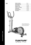
1
C4
OWN E R'S M AN UAL
P. 2 - 8
BE TRIE BS AN L E ITUN G
S . 9 -15
M OD E D 'E M PL OI
P. 16 -2 2
M AN UAL E D 'US O
P. 23 -2 9
M AN UAL D E L US UARIO
P. 3 0 - 3 6
H AN D L E ID IN G
P. 37- 4 3
BRUKS AN V IS N IN G
S . 4 4 - 50
KÄY TTÖOH JE
S . 51- 57
w ww.t un tu ri. co m
• S ERIAL NUM BER • S ERI E N N U M M E R
• NUM ERO D E S ERIE • N Ú M E R O D E SE R I E
• NUM ERO D I S ERIE • S E R I E N U M M E R
• S ERIENNUM M ER • S AR J A N U M E R O
I MP ORTA NT S A F E T Y
I NS TRU C T I ONS
Read this guide through carefully before assembling,
using or servicing your fitness equipment. Please
keep the guide somewhere safe; it will provide you
now and in the future with the information you need
to use and maintain your equipment. Always follow
these instructions with care. The equipment has
been designed for home use. The Tunturi warranty
applies only to faults and malfunctions in home use
(24 months). Please note that the warranty does not
cover damage due to shipping or negligence of
adjustment or maintenance instructions described in
this manual.
NO T E A BOU T
YO U R HEA LT H
• Before you start any training, consult a physician
to check your state of health.
• If you experience nausea, dizziness or other
abnormal symptoms while exercising, stop your
workout at once and consult a physician.
• To avoid muscular pain and strain, begin each
workout by warming up and end it by cooling down
(slow pedaling at low resistance). Don’t forget to
stretch at the end of the workout.
NO T E A BOU T T H E
EXER C I S I NG
ENVI RON M ENT
• The equipment is not to be used outdoors.
• Place the equipment on a firm, level surface. Place
the equipment on a protective base to avoid any
damages to the floor beneath the equipment.
• Make sure that the exercising environment has
adequate ventilation. To avoid catching cold, do not
exercise in a draughty place.
• In training, the equipment tolerates an environment
measuring +10°C to +35°C. The equipment can
be stored in temperatures ranging between -15°C
and +40°C. Air humidity in the training or storage
environment must never exceed 90 %.
OWNER'S MANUAL
•
C4
NO T E A BOU T U S I N G
T HE EQU I P M EN T
2
• If children are allowed to use the equipment, they
should be supervised and taught to use the equipment properly, keeping in mind the child’s physical
and mental development and their personality.
• Before you start using the equipment, make sure
that it functions correctly in every way. Do not use a
faulty equipment.
• Press the keys with the tip of the finger; your nails
may damage the key membrane.
• Never lean on the meter.
• Never remove the side covers. Do not step on the
frame casing.
• Only one person may use the equipment at a
time.
• Hold the handlebar for support when getting on or
off the equipment.
• Wear appropriate clothing and shoes when
exercising.
• Protect the meter from sunlight and always dry the
surface of the meter if there are any drops of sweat
on it.
• The equipment must not be used by persons
weighing over 110 kg.
• Make sure the equipment is unplugged before carrying out any assembly or maintenance procedures.
• Do not attempt any servicing or adjustments other
than those described in this guide. Everything else
must be left to someone familiar with the maintenance of electromechanical equipments and authorised under the laws of the country in question to
carry out maintenance and repair work.
• This product must be grounded. If it should malfunction or breakdown, grounding provides a path
of least resistance for electric current to reduce the
risk of electric shock. This product is equipped with
a cord having an equipment-grounding conductor
and a grounding plug. The plug must be plugged
into an appropriate outlet that is properly installed
and grounded in accordance with all local codes
and ordinances.
DANGER:
Improper connection of the equipment-grounding conductor can result in a risk of electric shock.
Check with a qualified electrician or serviceman if
you are in doubt as to whether the product is properly grounded. Do not modify the plug provided with
the product - if it will not fit the outlet, have a proper
outlet installed by a qualified electrician.
SAV E T H I S I N S T RU C T I O N M A N UA L
OWNER'S MANUAL
•
GB
C4
WELCOME TO THE WORLD
RE AR S UPPORT
OF TUNTURI EXERCISING!
Push the stand feet to the rear support ends and
attach the rear support to the main frame with two
bolts, washers, locking sleeves and nuts.
Your choice shows that you really want to invest
in your well being and condition; it also shows
you really value high quality and style. With
Tunturi Fitness Equipment, you’ve chosen a high
quality, safe and motivating product as your
training partner. Whatever your goal in training,
we are certain this is the training equipment
to get you there. You’ll find information about
using your exercise equipment and what makes
for efficient training at Tunturi’s website at
W W W.T U N T U R I .C O M .
A S S E M B LY
Start by unpacking the equipment. Two people are
needed for the assembly. Check that you have the
following parts:
1.
Frame
2 . Front support
3 . Rear support
4 . Front frame tube
5. Arms (2)
6 . Footrests (2)
7. Meter
8 . Handlebar
9. Shaft
10. Assembly kit (contents
F RON T F RAM E TUBE
Remove the rubber band from around meter cable
coming from the frame tube. Attach the meter
cable to the connector coming from the front
frame tube. Push the front frame tube inside the
frame tube: do not damage the meter cable! Attach
the front frame tube tight to the frame with the
washers and attachment screws.
marked with * in the
spare part list): keep the assembly tools, as you may
need them e.g. for adjusting the equipment
If necessary, please contact your dealer with the
model, equipment serial no. and spare part no.
of the missing part. You’ll find a spare part list at
the back of this guide. The packaging includes a
silicate bag for absorbing moisture during storage
and transportation. Please dispose of the bag once
you have unpacked the equipment. The directions
left, right, front and back are defined as seen from
the exercising position. Allow at least 100 cm of
clearance around the equipment.
FR ONT S U P P O R T
Attach the front support with transportation
wheels to the main frame with two bolts, washers,
locking sleeves and nuts.
ARM S
Push the metal shaft through the bracket housing
of the left arm. Attach now the left arm to the
front frame tube by pushing the metal shaft
through the opening in the tube. Push the right
arm on the shaft and lock it by tightening a large
washer, a locking sleeve and a screw to the both
ends of the shaft. Tighten the arms using two Allen
keys. Push the left footrest support forward so that
you can push the adjustment tube in the front of
the foot rest support inside the arm tube. Lock the
adjustment tube with the locking screw. Repeat the
procedure with the right footrest support.
The European model allows selecting
adjustment (see Adjusting the footrest supports).
NOTE !
3
in the center of the frame, and the other end into
the wall socket.
F OOT REST S
Attach the footrests to the position of your choice
on the pedal shafts with two screws, two washers /
screw and locking nuts.
The equipment must be connected to a
grounded wall socket. Do not use extension wires
when connecting the equipment to the power
source. Make sure the power cord does not run
underneath the equipment.
NOTE !
Always switch off the power and
unplug this appliance from the electrical outlet
immediately after using.
DA N G E R :
M ET ER A N D H A N D LE B A R
Remove the two attachment screws at the back
of the meter and the rubber band holding the
handlebar pulse cable. Attach the cable coming
from the front frame tube and the pulse cable
to the connectors of the meter. After connecting
the cables, thread them into the front tube. Lead
the pulse cable out through the hole in the front
tube. Push the meter into place on top of the front
frame tube and attach it with the two attachment
screws: do not damage the meter cable! Attach the
handlebar to the front frame tube with a clamp,
four screws and two sleeves / screw.
WA R N I N G : To reduce the risk of burns, fire,
electric shock, or injury to persons:
1) An appliance should never be left unattended
when plugged in. Unplug from outlet when not in
use, and before carrying out any maintenance or
repair procedures.
2) Do not operate under blanket or other
combustive material. Excessive heating can occur
and cause fire, electric shock, or injury to persons.
AD JUS TIN G TH E F OOTRE S T S UPPOR TS
(E UROPE AN M OD E L )
Turn the locking knob counterclockwise and pull
the locking knob out so that the adjusting tube can
be moved freely up and down. When the height is
right, let go of the knob. The tube locks into place.
Tighten the locking knob clockwise.
Always make sure that the locking knob is
fastened properly before starting to exercise. Adjust
the footrest support height so that the elliptic
movement does not strain your ankles.
NOTE !
OWNER'S MANUAL
•
C4
EXERCISING
4
T RA NS F O R M E R
Before connecting the equipment to a power
source, make sure that local voltage matches that
indicated on the type plate: the equipment operates
at either 230 V or 115 V (North American
version). Plug the socket end of the transformer
cord into the connector, just above the rear support
When you’ve not exercised for a long time,
you should have your condition checked and
consult a doctor, if you are over 40, your physical
condition is poor, you suffer from a chronic illness
or have health problems, or you have injuries
to or problems in your muscles. For endurance
exercising, it’s good to exercise at least 3 times a
week, but remember for your health that once
a week is better than not at all. The effects of
OWNER'S MANUAL
exercising will show after just a few weeks. If you’re
very unfit, start with a 20 minute workout. Once
your condition improves, you can train for 30-60
minutes depending on your goal.
EX ERC I S E L EV E L
The best training to improve your general fitness
is properly efficient, not too heavy and not too
easy. It’s good to sweat while working out, but
important still to be able to talk comfortably. This
type of exercise is called aerobic or endurance
exercise and your body produces the required
energy by burning body fat with the aid of oxygen.
This in turn leads to a reduction in fat tissue. No
matter what your goal, you’ll get the best results
by training at the right level of effort, and the best
measure is your own heart rate. First find your
maximum heart rate i.e. where the rate doesn’t
increase with added effort. If you don’t know your
maximum heart rate, please use the following
formula as a guide:
2 0 8 – 0, 7 X AG E
The maximum varies from person to person. The
maximum heart rate diminishes on average by one
point per year. If you belong to one of the risk
groups mentioned earlier, ask a doctor to measure
your maximum heart rate for you. We have defined
three different heart rate zones to help you with
targeted training.
• 50-60 % of maximum heart rate
Also suitable for weight-watchers, convalescents
and those who haven’t exercised for a long time.
Three sessions a week of at least a half-hour each
is recommended. Regular exercise considerably
improves beginners’ respiratory and circulatory
performance and you will quickly feel your
improvement.
BEGINNER
•
GB
C4
M E AS URIN G H E ART RATE
Pulse is measured by sensors in the handlebars.
Pulse is measured when the user of C4 is touching
both sensors simultaneously. Reliable pulse
measurement requires that the skin is constantly
touching the sensors and that the skin is slightly
moist. Too dry or too moist skin weakens the
reliability of hand pulse measurement.
The C4 meter has a heart rate receiver compatible
with Polar equipment, so you can also use Polar
uncoded heart rate transmitter belts for heart
rate measurement. The transmitter belt may be
purchased as an accessory.
TE L E M E TRIC H E ART RATE M E AS URE M E N T
The most reliable way of measuring the heart rate
is telemetric measurement using a transmitter
belt. If you want to measure your heart rate this
way during your workout, moisten the grooved
electrodes on the transmitter belt with saliva or
water. Fasten the transmitter just below the chest
with the elastic belt, firmly enough so that the
electrodes remain in contact with the skin while
pedaling, but not so tight that normal breathing
is prevented. If you wear the transmitter and belt
over a light shirt, moisten the shirt slightly at the
points where the electrodes touch the shirt. The
transmitter automatically transmits the heart rate
reading to the meter up to a Total Counts of about
1 meter. The heart rate value is displayed in the
meter. Follow your heart rate during the training.
RE M ARKS ON
TE L E M E TRIC M E AS URE M E N T
• 70-80 % of maximum heart
rate
Exercise at this level suits only the fittest and
presupposes long-endurance workouts.
If the electrode surfaces are not moist, the heart
rate reading will not appear on the display. If the
electrodes are dry, they must be moistened again.
Allow the electrodes to warm up properly to
ensure accurate heart rate measurement. If there
are several telemetric heart rate measurement
equipments next to each other, the Total Counts
between them should be at least 1.5 m. Similarly,
if there is only one receiver and several transmitters
in use, only one person with a transmitter should
be within transmission range. The transmitter is
switched to an active state only when it is being
used for measurement. Sweat and other moisture
can, however, keep the transmitter in an active state
and waste battery energy. Therefore it is important
to dry the electrodes carefully after use.
Rest is as important as exercise in a fitness program.
If you for instance exercise conscientiously for
three weeks, it’s good to make the following week a
little lighter.
When selecting training attire, please note
that some fibers used in clothes (e.g. polyester,
polyamide) create static electricity, which may
prevent reliable heart rate measurement.
T R A I N E R • 60-70 % of maximum heart rate
Perfect for improving and maintaining fitness.
Even reasonable effort develops the heart and lungs
effectively, training for a minimum of 30 minutes
at least three times a week. To improve your
condition still further, increase either frequency or
effort, but not both at the same time!
AC T I V E T R A I N E R
5
Please note that a mobile phone, television and
other electrical appliances form an electro-magnetic
field around them, which will cause problems in
heart rate measurement.
10. T O TA L C O U N T S / C O U N T S/M I N
This display alternates between Total Counts and
counts/min (speed).
11. KC A L / H R
METER
KEYS A N D D I SPLAY S
1. M A N UA L
Allows you to set your effort level with the arrow
keys during the workout.
2 . RO L L I N G H I L L S
This program changes the effort levels during
your workout. The display shows the program
and the changes in effort. You can choose a profile
to your liking by pushing the ROLLING HILLS key
repeatedly or with arrow keys. These programs can
be saved in the memory of the meter.
3 . H RC I N T E RVA L
This program changes the heart rate level during
your workout. The display shows the program and
the changes in target HR . You can choose a profile
to your liking by pushing the HRC INTERVAL key
repeatedly or with arrow keys. These programs can
be saved in the memory of the meter.
4 . TA RG E T H R
This program allows you to preset your heart
rate level, i.e. the resistance is regulated so that
your heart rate remains at the requested level. If
the heart rate tends to rise, resistance is reduced
automatically and vice versa. The set value can be
changed also during the workout.
5. R E S E T
Press for 2 seconds, RESETs all values.
6. ENTER
Approves set values and user parameters, activates
Quick Start-mode after pressing RESET.
This display alternates between approximate
energy consumption in kilocalories and heart
rate. Since people’s capacity to produce energy
varies, the energy consumption display shows an
approximation of the real consumption.
12 . S E L E C T I N G U N I T
You can select the unit of weight to be displayed by
the switch at the back of the meter housing. You
can select either kg or LB.
13 . T O TA L T R A I N I N G C O U N T E R
Press both arrow keys simultaneously and the TIME
window will present a total training time in hours.
O P E R AT I N G T H E M E T E R
Protect the meter from direct sunlight, as
it may damage the liquid crystal display. Do not
expose the meter to water or severe impacts, as
these may also damage the meter.
NOTE !
The meter switches on automatically when the
cycle is connected to the power source. The display
gives out a short beep after which all the functions
are at zero. If you do not press a key, or pedal for
more than 5 minutes, the meter automatically
switches off.
QUICK S TART
1. Switch on the meter or press ENTER after
pressing the RESET key.
2 . You can adjust the effort level (1-16) with the
arrow keys, and the columns indicate the chosen
effort level.
3 . Begin your workout.
M AN UAL
OWNER'S MANUAL
•
C4
7. S C A N H O L D
6
The values displayed change at 6-second intervals.
If you want to monitor any value for a longer
period, press the SCAN HOLD key, and the display
will be locked. When you want to view the
changing values again, press the SCAN HOLD key to
unlock.
8. A R ROW K E YS
Used for setting values, increasing or decreasing
resistance and selecting programs.
9. T I M E / E F FO R T ( W )
This display alternates between elapsed time and
effort in watts.
1. Select the
MANUAL key
manual function by pressing the
after the meter has been switched on
or after pressing the RESET key.
2 . The TIME display will start to flash. Choose the
desired duration of workout by using the arrow
keys (10-90 minutes in steps of 5 minutes). Press
ENTER . The equipment uses this value to calculate
the duration of the different effort levels during the
program.
3 . The Total Counts display starts to flash. The
display reads KG _. Enter your weight by using the
arrow keys (default value 70 kg). Press ENTER .
4 . Begin your workout.
5. You can adjust the effort level (1-16) with the
arrow keys, and the columns indicate the chosen
effort level.
OWNER'S MANUAL
•
RO L L I N G H I L L S P RO G R A M
TARG E T H R PROG RAM
Select the ROLLING HILLS program by pressing
the ROLLING HILLS key after the meter has been
switched on or after pressing the RESET key.
2 . The various effort levels are indicated by dots
on the display. By pressing the ROLLING HILLS key
repeatedly you get the display to show different
effort profiles (P1 - P4) and you can choose the
one best suited for you by pressing ENTER .
3 . The TIME display will start to flash. Choose the
desired duration of workout by using the arrow
keys (10-180 minutes in steps of 5 minutes, default
20 minutes). Press ENTER . The equipment uses
this value to calculate the duration of the different
effort levels during the program.
4 . The Total Counts display starts to flash. The
display reads KG _. Enter your weight by using the
arrow keys (default value 70 kg). Press ENTER .
5. Begin your workout.
6 . You can adjust the profile effort level with the
arrow keys (default 100 %), and the columns in
the display indicate the chosen effort level.
The TARGET HR program enables training at the
requested heart rate level. The program requires
measurement of heart rate.
1.
H RC I N T E RVA L P RO G R A M
The HRC INTERVAL program enables training at
the varying, requested pulse level. The program
requires measurement of heart rate.
Select the HRC INTERVAL program by pressing
HRC after the meter has been switched on or after
pressing RESET. The various target HR levels are
indicated by dots on the display. By pressing the
HRC key repeatedly you get the display to show
different profiles (P1 - P4) and you can choose the
one best suited for you by pressing ENTER .
2 . The TIME display will start to flash. Choose the
desired duration of workout by using the arrow
keys (10-180 minutes in steps of 5 minutes, default
20 minutes). Press ENTER . The device uses this
value to calculate the duration of the different
effort levels during the program.
3 . The Total Counts display starts to flash. The
display reads KG _. Enter your weight by using the
arrow keys (default value 70 kg). Press ENTER .
4 . Begin your workout. If the pedaling effort
seems too strenuous or easy, change the preset pulse
value (default 100 %) by using the arrow keys. The
columns in the display show the present target HR
level.
1.
Follow your heart rate during the training and
especially the heart indicator. The HR light should
flash in time with your heartbeat. If the indicator
begins to function in a disturbing fashion (e.g.
additional beats or abnormal fluctuations), the
pulse measurement is not functioning properly.
Stop your workout at once and make sure that you
have followed all the instructions described in this
manual about heart rate measurement.
GB
C4
1. Select the TARGET HR program by pressing
TARGET HR after the meter has been switched on or
after pressing RESET.
2 . The HR display will start to flash. Set the desired
heart rate value (default 110 bpm) by using the
arrow keys. Press ENTER. N O T E ! The preset value
can be changed during the training.
3 . The TIME display will start to flash. Choose the
desired duration of workout by using the arrow
keys (10-90 minutes in steps of 5 minutes). Press
ENTER . The equipment uses this value to calculate
the duration of the different effort levels during the
program.
4 . The Total Counts display starts to flash. The
display reads KG _. Enter your weight using the
arrow keys (default value 70 kg). Press ENTER .
5. Begin your workout. If the set heart rate value
seems too strenuous or easy, change the heart rate
value by using the arrow keys. The columns in the
display show the present heart rate level.
PAUS E
The values in a workout that has been interrupted
are saved in the memory of the meter for 5
minutes, after which they are RESET. You can restart
the interrupted exercise by pedaling within 5
minutes.
TRANSPORT AND STORAGE
Please follow these instructions when carrying
and moving the equipment about, because lifting
it incorrectly may strain your back or risk other
accidents:
Always switch the power off and unplug
the power cord before you start moving the
equipment around!
NOTE !
The device is easy to move by pushing along on the
integrated transport wheels. Tilt the device from
the front and push along the floor on the wheels at
the front support.
To prevent the equipment malfunctioning, store in
a dry place with as little temperature variation as
possible and protected from dust.
MAINTENANCE
The equipment requires very little maintenance.
Check, however, from time-to-time that all screws
and nuts are tight.
7
• After exercising, clean the equipment with a
soft, absorbent cloth. Do not use solvents. Sweat
may cause corrosion: we recommend therefore that
you protect all metal surfaces outside the plastic
covers with teflon or car wax.
• Never remove the equipment’s protective casing.
• If the equipment is not used for a period
of time, the transmission belt may become
temporarily distorted. This can lead to a sensation
of slightly uneven pedaling. However, after a few
minutes of use the effect disappears as the belt
returns to its original form.
N O T E ! If the equipment does not function
properly during use, contact your Tunturi dealer
immediately. Always give the model and serial
number of your equipment. Please state also the
nature of the problem, conditions of use and
purchase date. Despite continuous quality control,
defects and malfunctions caused by individual
components may occur in the equipment. In most
cases it’s unnecessary to take the whole equipment
in for repair, as it’s usually sufficient to replace the
defective part.
T E C H N I C A L S P E C I F I C AT I O N S
Length.........................
Width .........................
Height.........................
Weight ........................
130cm
61 cm
156 cm
61 kg
All Tunturi models meet the requirements of
the EU’s EMC Directives on electromagnetic
compatibility (89/336/EEC) and electrical
equipment designed for use within certain voltage
limits (73/23/EEC). This product therefore carries
the CE label.
The North American versions (115 V) comply
with FCC requirements on electromagnetic
compatibility and are accordingly marked with
the FCC label. The North American versions also
comply with the following safety standards: UL
1647 and CSA C 22. 2 No. 68-92.
OWNER'S MANUAL
•
C4
All Tunturi crosstrainers meet EN precision and
safety standards (Class A, EN-957).
8
Due to our continuous policy of product
development, Tunturi reserves the right to change
specifications without notice.
The instructions must be followed carefully
in the assembly, use and maintenance of your
equipment. The warranty does not cover damage
due to negligence of the assembly, adjustment
and maintenance instructions described herein.
Changes or modifications not expressly approved
by Tunturi Oy Ltd will void the user’s authority to
operate the equipment!
NOTE !
We wish you many enjoyable trainings with
your new Tunturi training partner!
C4
57
1
103 7040
Base frame
1
46
M5x10 DIN 7985
Screw
2
173 7011
Chain cover, left
1
47
203 7028
Fix handlebar (incl.48,83,84) 1
3
173 7012
Chain cover, right
1
48
403 7032
Pulse grip unit (incl.49)
4
533 7041
Turning plate cover
2
*50 653 7023
Spring knob, EUR
2
5
103 7041
Front foot
1
*-
Screw, USA
2
*6
M8x90 DIN 603
Screw
4
*51 653 7030
Screw
4
7
533 7042
Front foot cover
2
52
503 7017
Sensor bracket
1
*8
M8 DIN 137A
Washer
10
53
Mx12 DIN 7985
Screw
2
*9
M8 DIN 127
Spring washer
16
54
523 409 85
Bearing
4
2
*10 M8 DIN 1587
Cap nut
4
55
17 DIN 417
Clip C17 <ID 15.7mm>
3
11
103 7042
Rear foot
1
56
343 7020
Axle for pulley
1
12
533 7051
Rear foot cover
2
57
263 7007
Pulley (incl. 80)
1
13
403 7033
Sensor wire
1
58
503 7011
Safe bracket
1
14
403 7035
Cable set
1
59
M6x18 DIN 933
Screw
4
15
403 7034
Servo motor
1
60
M6 DIN 985
Nylock nut
4
16
M8x25 ISO 7380
Screw
2
61
513 7001
Bracket (incl. 54, 55)
1
17
513 7016
Macgnetic bow bracket
1
62
643 7001
Carge spring
1
19
203 7025
Upright tube, (incl. 36)
1
63
523 7014
Spacer sleeve
3
*20 653 7029
Screw
6
64
M6x14 DIN 933
Screw
3
21
523 9006
Bearing
8
65
373 7006
Magnetic bow
1
22
103 7043
Pedal tube, right (incl. 21)
1
66
M8x52 DIN 931
Screw
1
23
M8 DIN 125
Washer
2
67
M8 DIN 985
Nylock nut
1
24
M8x20 ISO 7380
Screw
4
68
223 7005
Metal wire
1
25
363 7005
Pedal, pair (incl. 35)
1
69
M6x10 DIN 7985
Screw
6
*26 M6x60 DIN 603
Screw
4
70
643 7002
Spring
1
*27 M6 DIN 125
Washer
11
71
403 7020 EU
Mains cable/transformer
1
*28 M6 DIN 127
Spring washer
8
-
403 7020 GB
Mains cable/transformer
1
*29 653 7022
Knob dawl
4
-
403 7020 USA
Mains cable/transformer
1
30
203 7037
Swivel tube, EUR (incl. 21)
2
-
403 7020 JPN
Mains cable/transformer
1
-
203 7029
Swivel tube, USA (incl. 21)
2
-
403 7020 AUS
Mains cable/transformer
1
31
653 7025
Washer
2
72
303 7002
Flywheel (incl.73-75,77,78)
1
32
343 7022
Pedal tube shaft
2
73
523 504 84
Bearing
2
33
533 7043
End cap
2
74
343 7021
Flywheel axle
1
34
103 7044
Pedal tube, left (incl 21)
1
75
12 DIN 471
Clip C12 <ID 11.1mm>
2
36
533 7044
Plug axle support
6
76
443 7003
Belt
1
*37 503 7015
Fix handlebar bracket
1
77
M10 DIN 125
Washer
2
38
343 7019
Axle support
1
78
653 7026
3/8” Wh nut
2
39
203 7026
Handle bar, RH, EUR
1
79
433 7007
Turning pedal, right
1
-
203 7030
Handle bar, RH, USA
1
80
403 7017
Magnet
1
(incl. 36,40,42,43)
81
433 7008
Turning pedal, left
1
40
533 7045
Plastic insert
2
82
M8x16 DIN 933
Screw
2
41
203 7027
Handle bar, LH, EUR
1
83
533 7046
Fix handlebar end cap
2
-
203 7031
Handle bar, LH, USA
1
84
213 7009
Fix handlebar grip
1
42
213 7008
Handle grip, pair
43
533 7047
(incl. 36,40,42,43)
85
M6x15 DIN 7985
Screw
1
2
86
M6 DIN 985
Nylock nut
1
Handlebar end cap
2
87
503 7018
Keep back bracket
1
*44 M8 DIN 440
Washer M8 OD 28mm
2
88
503 7019
Spring bracket
1
45
Computer (incl. 45a, 45b)
1
89
533 7052
Washer
2
Membrane
1
-
423 7052
Lable set
1
233 7015
45a 423 7057
58
653 7032
4
45b 173 1065
Meter lower cover
1
-
553 7006
Assembly kit (incl *)
1
-
Screw
6
-
583 7010
Owner’s manual
1
M3x8 DIN 7504 M
C4
43
84
42
51
45a
28
49
47
48
45
45b
20
9
44
89
42
36
14
36
36
83
37
43
27
41
46
50
40
39
38
50 US A model
36
36
19
7
36
30
89
21
44
16
21
31
9
9
6
14
8
50
5
26
50 US A model
33
14
24
40
35
9
23
21
20
31
9
27
32
2
28
30
21
8
32
21
1
29
33
26
34
25
21
71
8
9
3
10
8
9
8
12
4
9
6
28
21
10
16
27
22
29
9
11
24
21
23
69
14
55
54
54
78
87
77
61
62
69
82
75
74
53
9
72
73
1
88
54
73
75
77
55
81
78
27
85
13
64
52
65
63
54
17
55
60
58
56
69
70
15
59
76
80
57
68
79
65
67
82
66
59
www. tu ntu ri. c o m
TUNTURI OY LTD
P.O.BOX 750, FIN-20361
Turku, Finland
Tel. +358 (0)2 513 31
Fax +358 (0)2 513 3323
www.tunturi.com
5837010