1
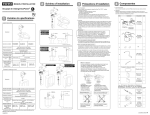
INSTALLATION INSTRUCTION FOR AUTOMATIC TOILET/URINAL FLUSH VALVE
Model Variation
Specification
Toilet Flush Valve
Water Supply
Top Spud
Back Spud
Floor
Back Spud
Wall
Figure
AC
DC
TET2ANS-32
TET2DNS-32
TET2ANS-33
TET2DNS-33
Urinal Flush Valve
Water Supply
Back Spud
Figure
TET2ANS-31
TET2DNS-31
Model TET2ANS TET2DNS TEU2ANS TEU2DNS
Number -32,33,31 -32,33,31 -11,21
-11,21
10V DC
Alkaline
10V DC
Alkaline
Supplied Type AA Supplied Type AA
Power
by AC
Batteries
supply
by AC
Batteries
Adapter 1.5V x 4pcs. Adapter 1.5V x 4pcs.
Dimensions
12-5/8"(H) x 14-3/16"(W)
(cover)
(320mm(H) x 360mm(W))
Within 31-1/2"(800mm)
Detection
from the front of the flush valve
range
Detection
6 seconds or more
time
Ambient
32-104˚F(0-40˚C)
temperature
(water temperature: 34-104˚F(1-40˚C))
Connection
of the water
1"NPT
3/4"NPT
supply pipe
Supply
Minimum required water pressure: 10 PSI (70kPa)
water
(flowing)
Pressure Maximum water pressure: 125PSI (862kPa)
Shutoff
7 PSI (48kPa)
pressure
Discharge
Approx.0.5 ~ 1.0gallon
quantity per
Approx.
1.6
gallon
(1.9 ~ 3.8L)
flush at 28 PSI
(6L)
(Fuzzy
logic adjusted
(196kPa)
flush
volume)
(Factory set)
4. Use care not to damage the surface of the infrared
sensor.
5. For Toilet Flush Valve
The toilet sensor valve may not function if toilet seat
and/or lid cover are left upright as it may block the
sensor.
6. For Urinal Flush Valve
The automatic flush valve is designed to be used with a
washout urinal for optimum performance. However, a
siphon jet urinal may also be substitutional. Blowout
urinals are not recommended.
Detection zone
The detection zone is self-adjusting and is equipped with a
3-second flush delay after removal from the detection zone.
(No flush delay for Urinal flush valve)
The detection zone may differ according to color of user’s
clothes.
When a user wears black clothes, the detection zone may
become smaller and the valve may not flush.
Flush pipe
AC
DC
3/4" O.D
TEU2ANS-11
TEU2DNS-11
1-1/4" O.D
TEU2ANS-21
TEU2DNS-21
Exploded View
For TET2ANS-32
2. Important
All plumbing is to be installed in accordance with
applicable codes and regulations.
Water supply lines must be sized to provide an
adequate volume of water for each fixture.
Flush all waterlines prior to operation.
The minimum pressure required to the valve is
determined by the type of fixture selected. Consult
fixture manufacturer for pressure requirement.
Do not use toothed tools to install or service the valve.
3. Main dimensions of the piping
For TET2ANS-32
Q’ty
Installation Procedure
Step 1
Only for toilet flush valve
C
Box
DC Type
1
Battery case
Determine the installation of the box fixing frame based on
the toilet/urinal position. Then determine the location of
the water supply pipe and attach the control stop to the
pipe. Thereafter bore a flush pipe guide hole in the wall.
Slide a thread solder adapter on the water supply pipe if
applicable.
Note
Only for toilet flush valve
Attach the control stop before installing the box fixing frame.
Vacuum
Breaker tube
D
Control stop
E
1
Location of the Left water
supply pipe
1"NPT for Toilet
3/4" for Urinal
4-3/4"
4-3/4"
(120mm) (120mm)
11-15/16"
(303mm)
1
1-9/16"
(40mm)
Box fixing frame
Toilet top spud
(2-3/16"(56mm)Dia. hole)
AC Type
DC Type
Connection
wire
13-1/2"
(343mm)
Urinal Back spud
(1-5/16"(33mm)Dia. hole)
2
11"
(279mm)
16"
(406mm)
Water
supply pipe
Toilet Back spud
(2-3/16"(55mm)Dia. hole)
15
Adapter
Max.31-1/2"
(Max.800 mm)
G
“AVOID”
DO NOT place the Infrared
sensor of one urinal so that
it is in line with the sensor
of another automatic flush
valve sensor.
“AVOID”
DO NOT place the Infrared
sensor in front of a
stainless steel wall or other
highly reflective surface.
Infrared sensor of the
automatic flush valve.
Stainless steel wall or other
highly reflective surface.
*For the Left water supply of Toilet flush valve
Tool
(Allen wrench)
1
Alkaline Type
AA Battery
4
DC Type
H
Slide the stopper up and remove the bracket from the
button. ( A )
Reinstall the bracket to the opposite direction shown in the
figure below. ( B )
Original
for the right water supply
Infrared sensor of the
automatic flush valve.
for the left water supply
Toilet Flush Valve
I
Notice Label
1
J
Owner’s
manual
1
A
Infrared sensor of the
another automatic
flush valve.
Location of the Right water
supply pipe
1"NPT for Toilet
3/4" for Urinal
Installation
Instruction
(this manual)
K
B
Bracket
Bracket
Stopper
1
Button
*16"(406mm)
4-3/4 1/2"
(120 13mm)
For TEU2DNS-11
Description
WARNING: To minimize the risk of electrical shock and
fire hazard, be sure to turn off and lock out
breaker for power line before starting the
installation.
F
Max.19-11/16"
(Max.500 mm)
Figure
AC Type
7. The detection range of the infrared sensor is shown in
the figure below.
Do not install a handrail or any other object within the
detection zone of the sensor, as object blocking the
sensor may cause the valve to malfunction.
Additionally, to avoid the possibility of valve malfunction,
do not install the flush valve in a location where the
sensor faces a stainless wall, other highly reflective
surface or another infrared sensor.
Installation Precautions
1. Prior to Installation
Prior to Installing your TOTO automatic flush valve,
install the items listed bellow:
· Closet fixture/Urinal fixture
· Drain line
· Water supply line
The supply piping to these devices shall be securely
anchored to the building structure to prevent the
installed device from unnecessary movement when
operated by the user. Care shall be exercised when
installing the device to prevent marring the exposed
significant surface.
Item
3-3/4"(95mm)
(For Max.1" wall)
1" NPT
TET2ANS-32
TET2DNS-32
Installation
DC Type
1. Required tools
Adjustable wrench, Phillips and slotted screwdrivers,
wire stripper and crimping pliers.
1-1/2" O.D.
Step 2
2. Inspection
Unpack the flush valve and carefully make sure the
cover, main unit and all other parts are included and
intact before starting installation of the product.
*check local codes
Item
Figure
Description
TET2ANS-33
TET2DNS-33
Q’ty
For TEU2DNS-11
4-3/4 1/2"
(120 13mm)
3-3/4"(95mm)
(For Max.1" wall)
3/4" NPT
Flush pipe
L
Main body
(with a set of
valve)
A
1
TET2ANS-31
TET2DNS-31
TEU2ANS-21
TEU2DNS-21
1
Go to
Step 4
For AC Type
Install the optional transformer Model (THU701TR,
INPUT:120VAC,60Hz, OUTPUT:10VDC,1.95A or
THU700TR, INPUT:24VAC,60Hz, OUTPUT:10VDC,1.95A)
according the instructions given later in the “Installation of
the Transformer” section of this manual, mount the
junction box on a pillar or the like, and guide the two lead
wires from the secondary side (10VDC) of the transformer
to the junction box. Also guide the lead wires for multiple
junction boxes.
From the secondary side
of the transformer
Conduit tube
*16"(406mm)
Only for toilet flush valve
*check local codes
Note
Refer to local codes for special requirements.
03666
To junction box
B
Manual flush button
(Only for toilet flush valve)
Front cover
(with an
infrared
sensor and
washer &
screw)
TEU2DNS-11
TEU2ANS-11
1
Conduit tube
Junction box
To be continued on the back
Step 3
Step 6
For AC Type
Join one lead wire, one supplied wire to flush valve and
one wire for another junction box using a wire nut. Join
the other sets of wires using another wire nut.
Fasten the connection wire to the cover of the junction
box.
Step 11
Make sure that the O-ring fits in the groove of the
connecting pipe.
Wire nut
Snap ring
To junction box
Test Run
For AC Type
Attach the connector of the infrared sensor unit with the
connector from the junction box. ( A )
Attach the connector of the infrared sensor unit with the
connector from the solenoid by using connection wire.
(B,C)
O-ring
Step 7
Supplied
connection wire
Connect the flush valve with the control stop and the
vacuum breaker.
To flush valve
sensor
B
A
Fasten the connection wire
C
Step 4
For DC Type
Step 8
Tighten the coupling nut to prevent a water leak.
Fasten the connection wire at the position of the mark
colored red with the clamp. ( C )
Coupling nut
B
Adjustable
plate
Box
Remove the battery case from the box.
Install the supplied 4 batteries into the battery case. Install
the battery case with the 4 batteries into the box exactly as
shown in the figure.
Connect the infrared sensor with the battery case by using
the connection wire.( A , B )
Connect the infrared sensor with the solenoid by using the
connection wire.( C , D )
Battery
Battery case
Coupling nut
C
D
Clamp
B
Step 9
Screw (Not used)
C
For Toilet flush valve
A
Insert the end of the stainless cable for manual flushing
into the hinge hole. ( A )
Slide the cable casing into the opening of the bracket. ( B )
Make sure the rod of the flush valve is thrusted when the
button is pushed.
Adjustable hole
Step 5
Pass the flush pipe and the vacuum breaker through the
hole bored in Step 1 and then mount them on the bowl.
For TET2ANS-32
TET2DNS-32
For TET2ANS-31
TET2DNS-31
Wall surface
Wall surface
1. The wiring distance from the transformer to the flush
valve must be 45 feet (13.5m) or less.
Use UL class ΙΙ No.18 wire when connecting the flush
valve to the transformer.
2. This transformer can be connected to a maximum of 10
flush valves.
4"SQ-2-1/4"DEEP
(CONDUCTKO’S)
Condult tube
Secondary-side lead wires
(10V DC,1.95A)
Note to the installer
Fasten the box to the box fixing frame with four screws (To
be prepare on the site) after adjusting it. ( A )
Secure the box with four screws attached to adjustable
plate. ( B )
For only AC Type
1. Energize the primary side of the transformer (THU701TR
or THU700TR) For AC Type
2. Make sure the control stop is open.
3. Sit on the toilet seat. (for Toilet flush valve)
Stand within two feet from the front of the flush valve.
(for Urinal flush valve)
4. Stay there for six seconds or more and leave the toilet
seat or the urinal. The valve will automatically flush.
5. Press the manual flushing button and make sure the
valve flushes properly. (for Toilet flush valve)
6. Recheck all the pipe connections for water leaks. If the
flush valve is not operating properly following the test
run consult the Troubleshooting section of the Owner’s
Manual. Recheck installation procedures only after
turning off and locking out breaker for power line
This automatic flush valve unit requires a special
transformer. When installing the transformer, please
observe the following instruction.
For the left water supply
Before installing the cable, the bracket should be
reinstalled to the opposit direction.
( C , and also see Step 1)
Original
for the right water supply
After the flush valve unit has been installed correctly,
please explain to your customer how to use it and tell him
or her to observe the following instructions.
1. Do not put any object in front of the sensor window
which could obstruct the sensor, causing the flush valve
to malfunction.
2. For troubleshooting, consult the Owner’s Manual.
1 To minimize the risk of electrical shock and fire
hazard, turn off and lock out breaker for power line
before attempting troubleshooting, maintenance,
adjustment or repairs.
2 If you lack the necessary skills required or have
difficulty following the directions for installation,
maintenance, repairs, troubleshooting or
adjustments, of the product, do not proceed without
help from a qualified person to assist you in
performing any of these functions.
A
Primary-side lead wires
(120V or 24V AC)
Transformer
WARNING: Be sure to ground the 4"SQ box to eliminate
the risk of electrical shock or fire hazard.
Never kink or bend primary-side lead wires
and/or secondary-side lead wires of the
transformer when wiring them in the conduit
tube or the junction box altogether.
Wiring
WARNING: To minimize the risk of electrical shock and
fire hazard, turn off and lock out breaker for
power line before starting wiring.
This product must be connected to the type of power
source indicated on the installation instruction. If you are
not sure of the type of power source available, consult
your dealer or local power company.
Adjustment
Step 12
Open the control stop.
Do not proceed to step 13 until all water leaks are
eliminated by tightening all the pipe connections. Failure to
correct all water leaks prior to use may increase the risk of
electrical shock, fire hazard or damage to the product.
WARNING: To minimize the risk of electrical shock and
fire hazard, turn off and lock out breaker for
power line before starting adjustment.
1. Adjustment of the discharge quantity
(1) Remove the front cover.
(2) Adjust the discharge quantity by rotating the screw
on the piston valve.
The wiring diagram is shown below.
When connecting the secondary side of the transformer
to each flush valve, use only UL Class ΙΙ No.18 wires.
- Wiring Diagram -
Two·pole beraker
for the left water supply
Control stop
Transformer
120VAC60Hz, to 10VDC(THU701TR)
1.95A
or
24VAC60Hz,to 10VDC(THU700TR)
1.95A
Open
6 6-1/2"
(152 165mm)
To increase
Cable casing
To decrease
Cable casing
1-1/2"
Top spud
Back spud
Wall mount
Unit #1
1-1/2"
Sensor
V1
5"
(127mm)
3"
(76mm)
Bowl
2-1/4" 2-3/4"
(57 70mm)
A
Stainless cable
Hinge
B
C
Hinge
Bowl
3-3/4"
(95mm)
Step 13
3-3/4"
(95mm)
Bracket
For TET2ANS-33
TET2DNS-33
For TEU2ANS-11,21
TEU2DNS-11,21
Wall surface
Solenoid valve
6VDC
Bracket
Step 10
Connect the chain from the front cover with a hole on the
Wall surface
V2
Unit #2
Fasten the front cover to the box by tightening the screws
with the supplied tool. (Allen wrench)
Take care so that any cord, wire or chain might not be
caught between the front cover and the box.
Sensor
V1
2. Adjustment of the flow rate
Adjust the flow rate by turning the screw/handle of the
control stop.
Turn the screw/handle to the right to decrease the flow
rate and turn it to the left to increase.
Solenoid valve
6VDC
Junction box
Junction box
V2
A maximum of ten units
can be connected.
Hole
3. Adjustment of the detection range
The detection range of the infrared sensor does not
need to be adjusted because it has been factory-preset.
Back spud
Floor mount
1-1/2"
Installation of the Transformer
3/4"or 1-1/4"
Allen wrench
Bowl
3-3/4"
(95mm)
3-3/4"
(95mm)
Manual flush button
(Only for toilet flush valve)
WARNING: Whenever installing the transformer or wiring,
turn off and lock out breaker for power line in
order to minimize the risk of electrical shock or
fire hazard.
Printed in August, 2001