1
TEC Thermal Printer
TRST-56 SERIES
Owner’s Manual
Table of Contents
CE Compliance (for EU only)
This product complies with the requirements of EMC and Low Voltage Directives including their
amendments.
WARNING
This is a Class A product. In a domestic environment this product may cause radio interference in
which case the user may be required to take adequate measures.
ATTENTION
Ce produit est de classe A. Dans un environnement domestique, il peut causer des interférences
radio.
Auquel cas, l’utilisateur sera amené à prendre les mesures adéquates.
Warnung
Dies ist ein Klasse A Produkt. In einer örtlichen Umgebung kann dieses Gerät Funkstörungen
verursachen.
Atención
Este es un producto de la clase A. En ambientes domésticos éste producto puede causar radio
interferencias en cuyo caso el usuario deberá tomar las medldas oportunas.
VERWITTIGING
Dit is een klasse A produkt. Het gebruik hiervan kan radio interferenties veroorzaken die de
gebruiker ertoe kunnen dwingen sommige maatregelen te moeten treffen.
Schallemission: unter 70dB(A) nach DIN 45635 (ISO7779)
FCC Notice
This equipment has been tested and found to comply with the limits for a Class A digital device,
pursuant to Part 15 of the FCC Rules. These limits are designed to provide reasonable protection
against harmful interference when the equipment is operated in a commercial environment. This
equipment generates, uses, and can radiate radio frequency energy and, if not installed and used in
accordance with the instruction manual, may cause harmful interference to radio communications.
Operation of this equipment in a residential area is likely to cause harmful interference in which case
the user will be required to correct the interference at this own expense.
Changes or modifications not expressly approved by manufacturer for compliance could void the
user’s authority to operate the equipment.
Copyright © 2001
by TOSHIBA TEC CORPORATION
All Rights Reserved
570 Ohito, Ohito-cho, Tagata-gun, Shizuoka-ken, JAPAN
Safety Summary
EO1-13016
6DIHW\6XPPDU\
Personal safety in handling or maintaining the equipment is extremely important. Warnings and Cautions
necessary for safe handling are included in this manual. All warnings and cautions contained in this manual
should be read and understood before handling or maintaining the equipment.
Do not attempt to effect repairs or modifications to this equipment. If a fault occurs that cannot be rectified
using the procedures described in this manual, turn off the power, unplug the machine, then contact your
authorised TOSHIBA TEC representative for assistance.
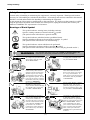
0HDQLQJVRI(DFK6\PERO
This symbol indicates warning items (including cautions).
Specific warning contents are drawn inside the symbol.
(The symbol on the left indicates a general caution.)
This symbol indicates prohibited actions (prohibited items).
Specific prohibited contents are drawn inside or near the symbol.
(The symbol on the left indicates “no disassembling”.)
This symbol indicates actions which must be performed.
Specific instructions are drawn inside or near the ● symbol.
(The symbol on the left indicates “disconnect the power cord plug from the outlet”.)
:$51,1*
$Q\ RWKHU WKDQ WKH
VSHFLILHG $& YROWDJH
LV SURKLELWHG
3URKLELWHG
3URKLELWHG
'LVFRQQHFW
WKH SOXJ
This indicates that there is the risk of death or serious injury if the
machines are improperly handled contrary to this indication.
Do not use voltages other than
the voltage (AC) specified on the
rating plate, as this may cause
fire or electric shock.
3URKLELWHG
If the machines share the same
outlet with any other electrical
appliances which consume large
amounts of power, the voltage
will fluctuate widely each time
these appliances operate. Be sure
to provide an exclusive outlet for
the machine as this may cause the
machines to malfunction.
Do not insert or drop metal,
flammable or other foreign
objects into the machines through
the ventilation slits, as this may
cause fire or electric shock.
3URKLELWHG
3URKLELWHG
If the machines are dropped or
their cabinets damaged, first turn
off the power switches and
disconnect the power cord plugs
from the outlet, and then contact
your authorised TOSHIBA TEC
representative for assistance.
Continued use of the machine in
that condition may cause fire or
electric shock.
'LVFRQQHFW
WKH SOXJ
(i)
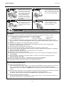
Do not plug in or unplug the power
cord plug with wet hands as this
may cause electric shock.
Do not place metal objects or
water-filled containers such as
flower vases, flower pots or mugs,
etc. on top of the machines. If
metal objects or spilled liquid enter
the machines, this may cause fire
or electric shock.
Do not scratch, damage or modify
the power cords. Also, do not
place heavy objects on, pull on, or
excessively bend the cords, as this
may cause fire or electrical shock.
Continued use of the machines in
an abnormal condition such as
when the machines are producing
smoke or strange smells may cause
fire or electric shock. In these
cases, immediately turn off the
power switches and disconnect the
power cord plugs from the outlet.
Then, contact your authorised
TOSHIBA TEC representative for
assistance.
Safety Summary
EO1-13016
'LVFRQQHFW
WKH SOXJ
&RQQHFW D
JURXQGLQJ ZLUH
If foreign objects (metal
fragments, water, liquids) enter
the machines, first turn off the
power switches and disconnect
the power cord plugs from the
outlet, and then contact your
authorised TOSHIBA TEC
representative for assistance.
Continued use of the machine in
that condition may cause fire or
electric shock.
Ensure that the equipment is
properly grounded. Extension
cables should also be grounded.
Fire or electric shock could
occur on improperly grounded
equipment.
'LVFRQQHFW
WKH SOXJ
1R
GLVDVVHPEOLQJ
When unplugging the power cords,
be sure to hold and pull on the plug
portion. Pulling on the cord portion
may cut or expose the internal wires
and cause fire or electric shock.
Do not remove covers, repair or
modify the machine by yourself.
You may be injured by high
voltage, very hot parts or sharp
edges inside the machine.
This indicates that there is the risk of personal Injury or damage to
&$87,21 objects if the machines are improperly handled contrary to this indication.
Precautions
The following precautions will help to ensure that this machine will continue to function correctly.
● Try to avoid locations that have the following adverse conditions:
* Temperatures out of the specification
* Direct sunlight
* High humidity
* Shared power source
* Excessive vibration
* Dust/Gas
● The cover should be cleaned by wiping with a dry cloth or a cloth slightly dampened with a mild
detergent solution. NEVER USE THINNER OR ANY OTHER VOLATILE SOLVENT on the plastic
covers.
● USE ONLY TOSHIBA TEC SPECIFIED paper and ribbons.
● DO NOT STORE the paper or ribbons where they might be exposed to direct sunlight, high
temperatures, high humidity, dust, or gas.
● Ensure the printer is operated on a level surface.
● Any data stored in the memory of the printer could be lost during a printer fault.
● Try to avoid using this equipment on the same power supply as high voltage equipment or equipment
likely to cause mains interference.
● Unplug the machine whenever you are working inside it or cleaning it.
● Keep your work environment static free.
● Do not place heavy objects on top of the machines, as these items may become unbalanced and fall
causing injury.
● Do not block the ventilation slits of the machines, as this will cause heat to build up inside the
machines and may cause fire.
● Do not lean against the machine. It may fall on you and could cause injury.
● Care must be taken not to injure yourself with the printer paper cutter.
● Unplug the machine when it is not used for a long period of time.
Request Regarding Maintenance
●
●
●
Utilize our maintenance services.
After purchasing the machine, contactiiyour authorised TOSHIBA TEC representative for assistance
once a year to have the inside of the machine cleaned. Otherwise, dust will build up inside the
machines and may cause a fire or a malfunction. Cleaning is particularly effective before humid rainy
seasons.
Our preventive maintenance service performs the periodic checks and other work required to maintain
the quality and performance of the machines, preventing accidents beforehand.
For details, please consult your authorised TOSHIBA TEC representative for assistance.
Using insecticides and other chemicals
Do not expose the machines to insecticides or other volatile solvents. This will cause the cabinet or
other parts to deteriorate or cause the paint to peel.
( ii )
EO1-13016
TABLE OF CONTENTS
Page
1. PRODUCT OVERVIEW --------------------------------------------------------------------------- 1- 1
1.1
Introduction---------------------------------------------------------------------------------------------------- 1- 1
1.2
1.3
1.4
Features-------------------------------------------------------------------------------------------------------- 1- 1
Applicable Model -------------------------------------------------------------------------------------------- 1- 1
Accessories --------------------------------------------------------------------------------------------------- 1- 2
2. SPECIFICATIONS---------------------------------------------------------------------------------- 2- 1
2.1
2.2
Printer ---------------------------------------------------------------------------------------------------------- 2- 1
Receipt Roll --------------------------------------------------------------------------------------------------- 2- 2
3. APPEARANCE-------------------------------------------------------------------------------------- 3- 1
3.1
3.2
Front/Rear View---------------------------------------------------------------------------------------------- 3- 1
Operation Panel---------------------------------------------------------------------------------------------- 3- 1
3.3
Connectors ---------------------------------------------------------------------------------------------------- 3- 2
4. SET UP PROCEDURE ---------------------------------------------------------------------------- 4- 1
4.1
4.2
5.
INSTALLATION PROCEDURE--------------------------------------------------------------------------------- 5- 1
5.1
5.2
5.3
5.4
5.5
6.
Connecting the Power Cord and Interface Cable--------------------------------------------------- 5- 1
Connecting the Drawer ------------------------------------------------------------------------------------ 5- 3
Loading the Receipt Roll ---------------------------------------------------------------------------------- 5- 3
Adjusting the Paper Near End Sensor Position ----------------------------------------------------- 5- 4
Self Test Print ------------------------------------------------------------------------------------------------ 5- 5
GENERAL MAINTENANCE ------------------------------------------------------------------------------------- 6- 1
6.1
6.2
7.
Requirements for Operation ------------------------------------------------------------------------------ 4- 1
Setting up the Printer --------------------------------------------------------------------------------------- 4- 2
Cleaning ------------------------------------------------------------------------------------------------------- 6- 1
6.1.1 Cleaning the Print Head and Platen ---------------------------------------------------------- 6- 1
6.1.2 Cleaning the Covers ------------------------------------------------------------------------------ 6- 1
Removing Jammed Paper -------------------------------------------------------------------------------- 6- 1
TROUBLESHOOTING -------------------------------------------------------------------------------------------- 7- 1
CAUTION!
1. This manual may not be copied in while or in part without prior written permission of TOSHIBA
TEC.
2. The contents of this manual may be changed without notification.
3. Please refer to your local Authorised Service representative with regard to any queries you
may have in this manual.
1. PRODUCT OVERVIEW
EO1-13016
1.1 Introduction
1. PRODUCT OVERVIEW
1.1 Introduction
Thank you for purchasing the TOSHIBA TEC TRST-56 Series Thermal Printer. This printer is a
compact line thermal printer designed to be connected to a TOSHIBA TEC POS terminal or used as a
kitchen printer, etc.
It prints an 80 mm-wide receipt at the maximum print speed of 150 mm/sec. The body colour is
selectable between fair white (FW-2) and stylish grey (SG) so that it is possible to coordinate the colour
with the TOSHIBA TEC POS terminal. The interface type is either Serial interface (RS-232C) or
Parallel interface (Centronics) according to the model type.
This manual contains general set-up and maintenance information and should be read carefully to help
gain the maximum performance and life from your printer. For most queries please refer to this manual
and keep it safe for future reference.
1.2 Features
•
•
•
•
•
•
•
•
•
Due to a paper drop-in mechanism, the paper replacement can be done by just dropping a new
paper roll and closing the cover. This also makes the print head cleaning easy.
This printer prints in thermal direct method at high speed (max. 150 mm/sec.) with less noise.
As the paper outlet is provided in front of the printer, the receipt can be taken out easily, and
flexible installation is possible.
Print layout can be variously arranged.
The power supply unit (AC adapter) is detachable from the printer.
A drawer interface (1 ch) is provided.
An automatic cutter is provided as standard. (Partial cut)
Two body colors are available for you to color coordinate with the TOSHIBA TEC POS terminal to
be connected.
User-defined characters and logos can be registered in the flash memory.
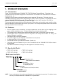
1.3 Applicable Model
• TRST-56-P-1W-QM
• TRST-56-S-1W-QM
• TRST-56-P-1G-QM
• TRST-56-S-1G-QM
Model name description
TRST-56-
-
-QM
Destination code
QM: Standard for worldwide
Body colour
W: Fair white (FW-2)
G: Stylish grey (SG)
Power cord
1: without power cord (local purchase)
Interface type
P: Parallel interface
S: Serial interface
NOTE: Some combinations of the above specifications are not developed as products. For details, please
refer to your nearest authorised TOSHIBA TEC representative.
1- 1
1. PRODUCT OVERVIEW
EO1-13016
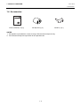
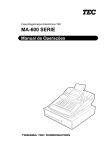
1.4 Accessories
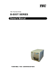
1.4 Accessories
TEC Thermal Printer
TRST-56 SERIES
Owner's Manual
TOSHIBA TEC CORPORATION
Owner’s Manual (1 copy)
Receipt Roll (1 pc.)
Partition (1 pc.)
NOTES:
1. The partition is provided for a case of using a 58 mm-wide receipt roll only.
2. The enclosed receipt roll is provided for an operation test.
1- 2
2. SPECIFICATIONS
EO1-13016
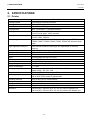
2.1 Printer
2. SPECIFICATIONS
2.1 Printer
Item
Printing method
Printing width
Resolution
Printing speed
Printing columns
Character size
Character types
Logo registration and print
Line spacing
Printable bar codes
Cut method
Paper
Interface
Input buffer
Supply voltage
Power consumption
AC adapter specification
Body colour
Operating temperature
Operating humidity
Storage temperature
Storage humidity
Weight
Dimension
Description
Line thermal dot printing method
72 mm (576 dots)
8x8 dots/mm (203 dpi)
Max. 150 mm/sec. (1,200 dot lines/sec.)
Font A (12 x 24 dots): 48/42 columns
Font B (9 x 24 dots): 64/56 columns
Font A: 1.25 x 3.00 mm
Font B: 0.88 x 3.00 mm
Alpha-numerals, International characters, Code pages PC850,
PC852, PC857, PC860, PC863, PC865, PC866 and Windows code
page
User defined characters and logos are registerable in the flash
memory.
4.23 mm (1/6 inch): selectable using the commands
UPC-A/E, EAN 13/8, ITF, CODE39, CODE128, CODABAR, CODE93
Partial cut
Thermal paper roll: 80 mm x ∅83
Serial (RS-232C) or Parallel (Centronics)
4K bytes/72 bytes
AC 100 - 240V ±10%, 50/60Hz
1 – 0.55A
Rated input: AC 100 - 240V, 50/60Hz, 1 - 0.55A
Rated output: DC 24V, 1.9A
Fair white (FW2) or Stylish grey (SG)
0°C to 40°C (Operation is guaranteed.)
5°C to 40°C (Print quality is guaranteed.)
20% to 90% RH (no condensation)
-20°C to 60°C
10% to 90% RH (no condensation)
2Kg (with AC adapter), 1.4 Kg (without AC adapter)
145 mm (W) x 190 mm (D) x 157 mm (H): with AC adapter box
145 mm (W) x 190 mm (D) x 114 mm (H): without AC adapter box
2- 1
2. SPECIFICATIONS
EO1-13016
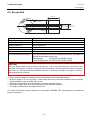
2.2 Receipt Roll
2.2 Receipt Roll
Width (W)
Paper
thickness (T)
Outer core
Inner core
diameter (ID) diameter (OD)
Outer
diameter (D)
Paper type
Width (W)
Outer diameter (D)
Paper thickness (T)
Weight
Outer core diameter
Inner core diameter
Recommended thermal paper
Thermal paper rolled with the print side facing outside
80 +0/-1 mm
80 +0.5/-1 mm
0.075±0.005 mm
69±3g/m2
18 mm
12 mm
Only paper rolled onto a core is acceptable, however, the paper end
should not be pasted to the core.
Normal paper:
PD150R OHJI PAPER (Japan)
Long storable paper: PD152R OHJI PAPER (Japan)
CAUTION!
Use only paper which meets specified requirements. Use of non-specified paper may shorten the
head life of the printer, resulting in problems with print quality, cause a paper feed failure or shorten
the cutter life. All paper should be handled with care to avoid any damage to the paper. Read the
following guideline carefully.
• Do not store the paper for longer than the manufacturer’s recommended shelf life.
• Store the paper in a cool, dry place. Avoid areas where they would be exposed to direct sunlight,
high temperature, high humidity, dust or gas.
• A contact of chemical or oil may discolour or erase the printed record.
• Rubbing the paper hard with nail or hard object may discolour the paper.
• The paper end should not be pasted to the core.
For further information please contact your authorised TOSHIBA TEC representative or authorised
paper manufacturer.
2- 2
3. APPEARANCE
EO1-13016
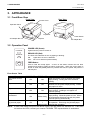
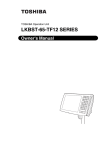
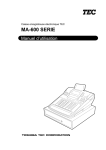
3.1 Front/Rear View
3. APPEARANCE
3.1 Front/Rear View
Front View
Printer Cover
Rear View
Operation Panel
Top Cover
Ejector
AC Adapter Box
Power Switch
AC Adapter Box
3.2 Operation Panel
POWER LED (Green)
POWER
ERROR
FEED
Lights when the power is turned on.
ERROR LED (Red)
The Error LED indicates an error by lighting or blinking.
ON:
Lights when an error is detected.
OFF: No error is detected. (Normal state)
FEED Button
Used to feed the receipt paper. A touch of this button causes one line feed.
Pressing and holding it feeds the paper continuously. When the power switch is
turned on while the [FEED] button is pressed and held, the printer will perform a
self test print.
Error Status Table
Error
The printer cover is
open.
POWER LED
ON
Paper near end
ON
Paper end
ON
The print head is
overheated.
Cutter motor is locked
by jammed paper.
ON
ON
ERROR LED
Solution
When the printer cover is opened, the printer
ON
stops printing. Closing the cover resumes
printing.
This error indicates that the paper is nearly
ON
finished, but the printer keeps printing. Load a
new paper roll soon.
When the paper has been used up, the printer
ON
stops printing. Loading a new paper roll
resumes printing.
When the print head is overheated, the printer
stops printing. Allow the printer to cool. When
Blinks slowly
the temperature becomes normal, the printer
resumes printing automatically.
Blinks slowly When the cutter motor is locked, the printer stops
+
the operation. Removing the jammed paper
Blinks quickly resumes the operation.
NOTE: If other LED status except for the above occurs, turn the power off, and then on. If this does
not restore the LEDs, contact your nearest TOSHIBA TEC representative for assistance.
3- 1
3. APPEARANCE
EO1-13016
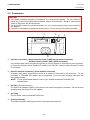
3.3 Connectors
3.3 Connectors
CAUTION!
1. The drawer interface connector is exclusively for connecting the drawer. Do not connect a
phone line or any other cables than the drawer cable to this connector. Doing so may cause a
failure of the phone line and this printer.
2. To the DC24V connector (socket connector), do not connect anything other than the built-in
AC adapter.
3. The built-in AC adapter is exclusively for this printer. Do not use it for any other machines.
c
d e
g
f
c[Interface connector] (Serial interface model: D-SUB 25-pin Socket Connector,
Parallel interface model: IEEE 1284-B receptacle)
An interface cable which connects the printer to a POS terminal is connected to this connector.
A Centronics interface cable (Parallel I/F model) or an RS-232C interface cable (Serial I/F model)
is connected.
d [Drawer interface connector] (6-pin modular connector)
A drawer cable which connects the printer to a drawer is connected to this connector. To this
connector, a TOSHIBA TEC drawer can be connected. Do not connect anything other than the
connectable drawer.
NOTE: For the connectable drawers, refer to your nearest authorised TOSHIBA TEC
representative.
e [DC24V] (Socket connector)
The built-in AC adapter supplies +24V power to the printer through this connector. Do not connect
anything other than the built-in AC adapter.
f[AC Inlet]
The AC power cord is connected to this inlet.
g [Ground terminal]
The drawer interface cable’s ground wire is secured to this terminal.
3- 2
4. SET UP PROCEDURE
EO1-13016
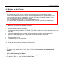
4.1 Requirements for Operation
4. SET UP PROCEDURE
4.1 Requirements for Operation
This printer has the following requirements:
Serial interface Type
• The TOSHIBA TEC POS terminal to be connected must have a serial port.
• To communicate with the TOSHIBA TEC POS terminal, an RS-232C interface cable is required.
RS-232C cable........ 25 pins
Parallel Interface Type
• The TOSHIBA TEC POS terminal to be connected must have a Centronics parallel port.
• To communicate with the TOSHIBA TEC POS terminal, a Centronics interface cable is required.
Centronics cable ..... 36 pins
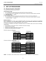
Interface Cables
For the serial interface model, use the CBLST-50-2-QM serial printer cable available from TOSHIBA
TEC or equivalent. For the parallel interface model, use the Centronics cable which satisfies the
following pin configuration and the specification of the connector.
To prevent the emission and receipt of electrical noise, the interface cable must meet the following
requirements:
• Fully shielded and fitted with metal or metalized connector housings.
• Kept as short as possible.
• Should not be tightly bundled with the power cord.
• Should not be tied to power line conduits.
RS-232C cable pin configuration
POS terminal side
D-SUB 9-pin female
PIN No.
Case
2
3
8
4
5
6
Printer side
D-SUB 25-pin male
Signal
FG
RXD
TXD
CTS
DTR
GND
DSR
PIN No.
1
2
3
4
6
7
20
Centronics cable pin configuration
POS terminal side
D-SUB 25-pin male
PIN No.
1
2-9
10
11
12
13
14
16
15
17
18-25
Signal
FG
TXD
RXD
RTS
DSR
GND
DTR
Printer side
IEEE1284-B receptacle
Signal
/STROBE
PD1-8
/ACK
BUSY
PERROR
SELECT
/AUTOFD
/INIT
/FAULT
/SELECTIN
GND
PIN No.
1
2-9
10
11
12
13
14
31
32
36
19-30
15-18
33-35
Signal
/STROBE
PD1-8
/ACK
BUSY
PERROR
SELECT
/AUTOFD
/INIT
/FAULT
/SELECTIN
GND
N.C.
N.C.
NOTE: For details of the interface cable, contact your nearest TOSHIBA TEC representative.
4- 1
4. SET UP PROCEDURE
EO1-13016
4.2 Setting up the Printer
4.2 Setting up the Printer
CAUTION!
1.
2.
3.
4.
Place the printer on a flat, stable surface.
Do not place the printer close to a heater or where it may be exposed to direct sunlight.
Avoid locations where the printer may be exposed to high temperature, high humidity or dust.
Care must be taken that no condensation occurs in the printer. If it should, however, do not
turn ON the power until the condensation is dried.
5. Use a grounded electrical outlet. Do not use an adapter plug.
6. Be sure that there is adequate room around the printer for easy operation and maintenance.
7. Keep your work environment static free.
1)
2)
3)
4)
5)
6)
7)
8)
9)
10)
11)
Make sure that the printer power is turned OFF.
Connect the interface cable to the printer.
Insert the power cord into the AC inlet.
Connect the interface cable to a TOSHIBA TEC POS terminal, and plug in the power cord to the
AC outlet.
If a drawer is desired to be connected, connect the drawer interface cable to the printer.
Secure the drawer ground wire to the ground terminal on the rear of the printer.
Turn the printer power ON.
Open the printer cover.
Load the receipt roll into the printer.
Close the printer cover. One receipt will be automatically issued.
Check the print quality by performing a self test print.
Now the printer is ready for printing.
NOTES:
1. For details of the above steps 1) to 4), refer to Section 5.1 Connecting the Power Cord and
Cables.
2. Steps 5) and 6) are the procedures of the drawer connection. For details of Steps 5) and 6), refer to
Section 5.2 Connecting the Drawer.
3. For details of Steps 8) to 10), refer to Section 5.3 Loading the Receipt Roll.
4. For details of Step 11), refer to Section 5.5 Self Test.
4- 2
5. INSTALLATION PROCEDURE
EO1-13016
5.1 Connecting the Power Cord and Interface Cable
5. INSTALLATION PROCEDURE
WARNING!
1. Since the power cord and the interface cable are not provided with this unit, please locally
purchase ones which meet the specifications. For detail specifications, please contact your
nearest authorised TOSHIBA TEC representative.
2. Before connecting the power cord and cables to the printer, turn the power of the POS
terminal and printer OFF.
3. Do not pull the power cord hard. Doing this may damage the power cord, causing fire, electric
shock, or broken wire.
4. When it thunders, unplug the power cord. Lightning stroke may cause fire or electric shock.
5. Keep the power cord away from a heater. The cover of the power cord may be melted,
causing fire or electric shock.
5. Do not connect the power cord to the AC outlet provided on the POS terminal such as ST5600, ST-5500, etc.
CAUTION!
1. When separating the AC adapter, please contact your authorized TOSHIBA TEC
representative.
2. The built-in AC adapter is exclusively for this printer. Do not use it for any other machines.
3. The AC adapter can be used indoors only. Never use it outdoors.
4. Be sure to unplug the printer when it is not used for a long time.
5. Do not share the power source with other electric appliances which generate noise.
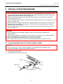
5.1 Connecting the Power Cord and Interface Cable
CAUTION!
1. Be sure to hold the connector when plugging in or unplugging the AC adapter cable.
2. Insert the AC adapter cable and the power cord firmly.
1) Turn the printer power OFF.
2) Insert the power cord into the AC inlet.
AC Inlet
Power Cord
AC Adapter Cable
5- 1
5. INSTALLATION PROCEDURE
EO1-13016
5.1 Connecting the Power Cord and Interface Cable
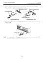
3)
Connect and secure the interface cable to the interface connector in the correct orientation.
Serial interface:
Secure the connector with the screws.
Parallel interface: Secure the connector with the locking tabs.
Serial Interface Connector
Parallel Interface Connector
Locking Tab
Serial Interface Cable
Locking Tab
Parallel Interface Cable
[Serial Interface Type]
4)
[Parallel Interface Type]
Connect the interface cable to the TOSHIBA TEC POS terminal, and then plug in the power cord
to the AC outlet.
Interface Cable
LPT1
NOTE: The above figure shows the example of the interface cable which is connected to the LPT1
port (Parallel interface) on the ST-5600 POS terminal.
5- 2
5. INSTALLATION PROCEDURE
EO1-13016
5.2 Connecting the Drawer
5.2 Connecting the Drawer
CAUTION!
The drawer interface connector is exclusively for connecting a drawer. Do not connect a phone
line or any other cables than the specified drawer cable. Doing so may cause a failure of the
phone line and the printer.
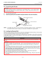
1)
2)
3)
Turn the printer power OFF.
Connect the drawer cable to the drawer interface connector in the correct orientation.
Secure the ground wire of the drawer to the ground terminal on the rear of the printer.
Drawer Interface Connector
Ground Terminal
Drawer Cable
Ground Wire
NOTE: A TOSHIBA TEC drawer can be connected to the drawer interface connector. Regarding the
connectable drawers, please contact your authorised TOSHIBA TEC representative.
5.3 Loading the Receipt Roll
When you use this printer for the first time or when the receipt paper has been used up, load a receipt
roll in the following procedures while the printer power is set to ON.
A thermal printer prints thermal receipt paper by applying heat to the paper to react with the chemicals
on the paper surface. A red line which appears on the reverse side of the receipt paper indicates that
the paper is almost used up.
WARNING!
The print head becomes very hot while printing. Never touch the print head to avoid getting
burned.
CAUTION!
1. Use only TOSHIBA TEC specified paper. Use of non-specified paper may shorten the print
head life resulting in problems with print quality, cause a paper feed failure, or shorten the
cutter life.
2. Do not subject the thermal receipt roll to water, oil, or heat source as this will darken the paper.
3. Load the receipt roll in the correct orientation. Failure to do this may cause a paper jam error.
4. Care must be taken not to damage the print head and platen when the printer cover is opened
as this may cause a poor print or a printer failure.
5. Do not open the printer cover while the printer is printing.
6. Do not hold the receipt while the printer is printing. Doing so may cause a paper jam.
7. When closing the printer cover, do not press it down too hard.
8. Do not put anything on the printer cover or push the cover too strongly. Doing so may cause a
print failure.
5- 3
5. INSTALLATION PROCEDURE
EO1-13016
5.4 Adjusting the Paper Near End Sensor Position
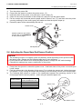
1)
2)
3)
4)
5)
6)
Turn the printer power ON.
Press down the ejector to unhook the printer cover. (c)
Hold both sides of the printer cover and open it until it stops.(d)
Check for the correct orientation of the receipt roll, and put it into the paper holder.
Pull the receipt until it extends past the paper outlet for about 5 cm (e), and then close the printer
cover by pressing it’s front centre gently and make sure that the ejector snaps up.
Excessive paper will be automatically fed and cut.
Print Head
Printer Cover
2
Caution symbol for hot surface.
(Please refer to the WARNING!
on the previous page.)
Ejector
3
1
Receipt Roll
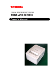
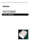
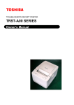
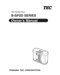
5.4 Adjusting the Paper Near End Sensor Position
CAUTION!
1. The remaining volume of roll paper (outer roll diameter) varies depending on the printer models
and paper types. Please use the following table just for your reference.
2. Do not open the DIP switch cover under the paper holder or change the DIP switch settings.
Changing the settings may cause a malfunction of the printer.
1)
2)
3)
Press down the ejector to unhook the printer cover. Hold both sides of the printer cover and open
it until it stops.
Push the sensor tab in the direction of the arrow (c) to unhook the sensor tab. Adjust the sensor
unit position (d) by moving the sensor tab according to the remaining volume of the receipt paper.
The following table shows an outline of the relationship between the remaining volume of the
receipt paper and the sensor position. (when using the specified paper roll)
Sensor position
1
2
3
4
Remaining volume
(Outer roll diameter: mm)
∅18
∅21
∅24
∅27
Sensor Tab
4 3 21
Sensor Position
1
2
Sensor Unit
5- 4
DIP Switch Cover
5. INSTALLATION PROCEDURE
EO1-13016
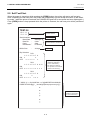
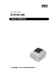
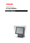
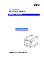
5.5 Self Test Print
5.5 Self Test Print
When the power is turned on while pressing the [FEED] button, the printer will start a self test print.
After completing the self test print, the printer will automatically cut the receipt and return to the standby mode. (while the printer is restored, the POWER LED goes off for a moment and soon lights again.)
If the [FEED] button is kept pressed while the printer is restored, the self test print will be performed
again.
TRST-56
MPVX.XX
LPVX.XX
Firmware Version
Loader Version
Serial Interface
Baud Rate
Data Bit
Parity
Handshake
:
:
:
:
9600 bps
8 bits
Odd
DTR/DSR
Buffer Size
:
4K byte
Interface Type
Communication Specification
(Serial Interface model only)
Buffer Size
Dip Switches
DS1
1 2 3 4 5 6 7 8
ON o
o
OFF
o o o o o
o
Dip Switch Settings
(Different depending
on the destination)
Dip Switch 3 settings
are printed for the Serial
Interface model only)
DS2
1 2 3 4 5 6 7 8 9 10
ON
OFF o o o o o o o o o o
DS3
1 2 3 4 5 6 7 8
ON
o
OFF o o o o
o o o
!” #$%&’ ()*+-./0123456789:;<=>?@ABCDEFGHIJKLMNO
PQRSTUVWXYZ[ ] ^ _ ‘abcdefghijklmnopqrstuvwxyz{|}~
Printable Characters
(Different depending
on the destination)
5- 5
6. GENERAL MAINTENANCE
EO1-13016
6.1 Cleaning
6. GENERAL MAINTENANCE
WARNING!
1. Be sure to disconnect the power cord prior to performing any maintenance.
2. DO NOT POUR WATER directly onto the printer, as this may cause electric shock or fire.
3. The print head becomes very hot while printing. To avoid getting burned, never touch the print
head during the maintenance.
CAUTION!
1. Do not use any sharp object to clean the print head and platen. Doing so may damage them,
causing poor print or missing dots.
2. Never use an organic solvent like thinners or benzene for cleaning. Using such solvents may
discolour the covers.
3. Do not touch the print head element as static built-up may damage the print head.
To help retain the high quality and performance of your printer it should be cleaned regularly. The
greater the usage on the printer, the more frequent the cleaning. (i.e. low usage=weekly, high
usage=daily)
6.1 Cleaning
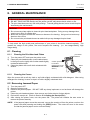
6.1.1
1)
2)
3)
Cleaning the Print Head and Platen
Turn the power OFF and open the printer cover.
Clean the print head element (cross hatched area
in the figure on the right) with a cotton swab slightly
moistened with alcohol.
Clean the platen with a soft cloth moistened with
alcohol.
6.1.2
Print Head
Element
Caution symbol for
hot surface.
(Please refer to the
WARNING! on the
above.)
Platen
Cleaning the Covers
Wipe the covers with a soft dry cloth or soft cloth slightly moistened with mild detergent. After using
detergent for cleaning, be sure to wipe it off with a slightly moistened cloth.
6.2 Removing Jammed Paper
1)
2)
3)
4)
5)
6)
Turn the power OFF.
Open the printer cover.
Remove the jammed paper. DO NOT USE any sharp implement or tool as these will damage the
printer.
Clean the print head and platen, then remove any further dust or foreign objects.
Re-load the receipt roll. (Refer to Section 5.3 Loading the Receipt Roll.)
After closing the printer cover, turn the power ON. The printer will initialise the auto cutter to
restore the printer stand-by.
NOTE: If the jammed paper cannot be removed, remove the receipt roll from the printer, and turn the
power ON while pressing and holding the [FEED] button. The cutter will move to the center
so that the jammed paper can be removed easily.
6- 1
7.TROUBLESHOOTING
EO-13016
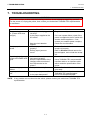
7. TROUBLESHOOTING
7. TROUBLESHOOTING
WARNING!
If you cannot solve a problem with the following solutions, do not attempt to repair it by yourself.
Turn the power off, unplug the printer, then contact your authorised TOSHIBA TEC representative
for assistance.
Problem
The power is not turned
on. (Power LED does
not light.)
Receipt paper is not
issued.
Check Pint
• Is the power cord plugged in
correctly?
• Is the power supplied to the
AC outlet?
• Has the circuit breaker
tripped?
• Is the receipt roll loaded
properly?
• Does a paper jam error
occur?
No printing is performed • Is the interface cable
though the POWER LED
connected correctly?
lights.
• Does the specification of the
interface cable meet that of
the POS terminal or the
printer?
Issued receipt paper is
• Is the print head dirty?
stained.
Irregular print/blurred
• Is the proper paper used?
print
• Is the paper dampened?
Solution
• Plug it in correctly.
• If it is not a power failure, check if the
power is supplied to the AC outlet with
another electric appliance. If not,
contact your nearest power company.
• Check the circuit breaker.
• Refer to Section 5.3 and load the
receipt roll properly.
• Refer to Section 6.2 and remove the
jammed paper, and re-load the receipt
roll.
• Connect the interface cable correctly.
• Use a TOSHIBA TEC-recommended
interface cable or an interface cable
which meets the specification of the
printer.
• Refer to Section 6.1 and clean the
print head.
• Refer to Section 2.2 and use the
TOSHIBA TEC specified paper.
• Do not use dampened paper.
NOTE: If any problem occurs other than the above, please contact your authorised TOSHIBA TEC
representative.
7- 1
INDEX
EO1-13016
INDEX
INDEX
A
O
AC adapter ..........................................1-1, 2-1
AC adapter cable ....................................... 5-1
AC adapter box .......................................... 3-1
Accessories ................................................ 1-2
Operation Panel ......................................... 3-1
ERROR LED......................................... 3-1
FEED Button......................................... 3-1
POWER LED ........................................ 3-1
Outer core diameter ................................... 2-2
Outer diameter (D) ..................................... 2-2
C
Character size ............................................ 2-1
Character types .......................................... 2-1
Centronics cable pin configuration............. 4-1
Cleaning ..................................................... 6-1
Connector................................................... 3-2
Parallel interface model ........................ 3-2
Serial interface model ........................... 3-2
Cut method ................................................. 2-1
D
Dimension .................................................. 2-1
DIP switch cover......................................... 5-4
Drawer ........................................................ 5-3
Drawer cable .............................................. 5-3
Drawer interface connector .................3-2, 5-3
P
Paper thickness (T).................................... 2-2
Paper type.................................................. 2-2
Parallel interface type ................................ 4-1
Partition ...................................................... 1-2
Platen ......................................................... 6-1
Power consumption ................................... 2-1
Power switch .............................................. 3-1
Print head................................................... 5-4
Printer cover............................................... 3-1
Printing method .......................................... 2-1
Printing speed ............................................ 2-1
R
E
Receipt roll .......................................... 2-2, 5-4
RS-232C cable pin configuration............... 4-1
Ejector .................................................3-1, 5-4
Error status table........................................ 3-1
S
I
Inner core diameter ................................... 2-2
Interface...................................................... 2-1
Interface cable ............................................ 4-1
Self test print .............................................. 5-5
Serial interface type ................................... 4-1
Specifications ............................................. 2-1
Sensor tab.................................................. 5-4
T
J
Jammed paper ........................................... 6-1
Top cover ................................................... 3-1
Troubleshooting ......................................... 7-1
W
Weight (Printer) .......................................... 2-1
Weight (Receipt roll) .................................. 2-2
Width (W) ................................................... 2-2
E
PRINTED IN JAPAN
EO1-13016