1
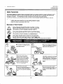
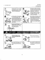
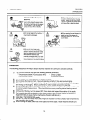
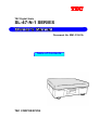
TEC
TEC Digital Scale
SL-47-N-1 SERIES
Document No. EM1-31061A
Table of Contents
TEC CORPORATION
EM-31061A
TABLE OF CONTENTS
Page
..................................................
1. INTRODUCTION
2. APPLICABLE
MODEL
3- 1
4- 1
.....................................................
5. LEVEL ADJUSTMENT
6. INSTALLING
7. CONNECTING
..............................................
THE REMOTE
PIPE
THE INTERFACE
8. TROUBLESHOOTING
9. BEFORE
2- 1
..............................................
.................................................
3. SPECIFICATIONS
4. OVERVIEW
l- 1
5- 1
5- 1
.....................................
CABLE AND REMOTE
CABLES
..............
7- 1
8- 1
..............................................
YOU CALL FOR SERVICE
8- 1
....................................
CAUTION:
I.
This manual
may not be copied
2.
The contents
3.
Please refer to your local Authorized
have in this manual.
of this manual
in whole or in part without prior written permission
may be changed
Service
without
of TEC.
notification.
representative
with regard
to any queries
you may
iI
l-14-10
Uchiksnda.
Chlyode-ku,
Tokyo.
JAPAN
EMl-3106lA
1. INTRODUCTlON
I. INTRODUCTION
1. INTRODUCTION
We thank you very much for purchasing
been designed with TEC reliability.
Should you have any questions
this manual for future reference.
concerning
the TEC
Digital Scale SL47-N-1
Series.
This series
the scale, please refer to this manual.
has
Be sure to keep
This equipment
has been tested and found to comply with the limits for a Class A digital device,
These limits are designed to provide reasonable
protection
pursuant to Part 15 of the FCC Rules.
This
against harmful interference
when the equipment
is operated in a commercial
environment.
equipment
generates,
uses, and can radiate radio frequency energy and, if not installed and used in
accordance
with the instruction
manual, may cause harmful interference
to radio communications.
Operations
of this equipment in a residential area is likely to cause harmful interference
in which case
(for USA only)
the user will be required to correct the interference
at his own expense.
Changes
authority
or modifications
not expressly
to operate the equipment.
approved
by manufacturer
for compliance
could void the user’s
“This Class A digital apparatus meets all requirements
of the Canadian Interference-Causing
Equipment
Regulations.”
“Cet appareil numerique
de la classe A respecte toutes les exigences du Reglement
sur le materiel
(for CANADA only)
brouilleur du Canada.”
I
WARNlNG
This is a Class A product.
In a domestic environment
this product
which case the user may be required to take adequate measures.
As the colours of the cores in the mains lead of this equipment
markings identifying the terminals in your plug, proceed as follows:
l
l
l
the core which is coulored green and
which is marked with the letter E or by
the core which is coloured blue must
letter N or coloured black.
the core which is coloured brown must
letter L or coloured red.
This equipment
Safety
may cause
radio
interference
in
I
may not correspond
with the colour
yellow must be connected
to the terminal in the plug
the earth symbol, or colored green and yellow,
be connected to the terminal which is marked with the
be connected
to the terminal
which
is marked
with the
must be earthed.
Summary
Personal
safety in handling or maintaining
the equipment
is extremely
important.
Warnings
and
Cautions necessary for safe handling are included in this manual. All warnings and cautions contained
in this manual and written inside or outside of the scale should be read and understood
before handling
or maintaining the equipment.
Do not attempt to effect repairs to this equipment.
If a fault occurs that cannot be rectified using the
procedures
described
in this manual, turn off the power, unplug the machine,
then contact your
authorised TEC representative
for assistance.
l- 1
1.
EMl-31061A
INTRODUCTION
1. INTRODUCTION
Safety Precautions
This Owner’s Manual and the products (machines) which you have purchased contain indications which
should be observed in order to use the machines safely and prevent harm to yourself and others and
damage to property. The meanings of these indications and symbols are given below.
Read these indications and become familiar with their contents before reading this Owner’s Manual.
The following safety precaution will help to ensure proper use of the scale.
Unplug the printer whenever you are working inside the scale.
Keep your work environment
static free.
Meanings of Each Symbol
A
This symbol indicates warning items (including cautions).
Specific warning contents are drawn inside the Asymbol.
(The symbol on the left indicates a general caution.)
1
0
This symbol indicates prohibited actions (prohibited items).
Specific prohibited contents are drawn inside or near the 6~ symbol.
(The symbol on the left indicates “no disassembling”.)
cs
This symbol indicates actions which must be performed.
Specific instructions are drawn inside or near theOsymbol.
(The symbol on the left indicates “disconnect the power cord plug from the outlet”.)
Prohibited
w Do not plug in or unplug the power
cord plug with wet hands as this may
cause electric shock.
c1
11
S If the machines share the same
outlet with any other electrical
appliances which consume large
amounts of power, the voltage will
fluctuate widely each time these
appliances operate. Be sure to
provide an exclusive outlet for the
machine as this may cause the
machines to malfunction.
n Do not insert or drop metal,
flammable or other foreign objects into
the machines through the veniitation
this may cause fire or electric
n Do not use voltages
w
4ny other than the
rptxifkd
AC voltage
is
xohibiled.
d?~Gl
(;;;I
other than the
voltage (AC) specified on the rating
plate, as this may cause fire or
electric shock.
n Do not place
Prohibit&
metal objects or
water-filled containers such as flower
vases, flower pots or mugs, etc. on
top of the machines.
If metal objects
or spilled liquid enter the machines,
this may .cause fire or electric
shock.
H Do not remove covers, repair or
modify the machine by yourself. You
may be injured by high volta e, very
hot parts or sharp edges ins13 e the
machine.
EMl-31061A
1. INTRODUCTION
1. INTRODUCTION
Prohibited
immediately turn off the power
switches and disconnect the power
s from the outlet. Then,
n If foreign objects
(metal fragments,
water, liquids) enter the machines, first
turn off the power switches and
disconnect the power cord plugs from
the outlet, and the contact your sales
agent (or maintenance and service
agent). Continued use of the machine
in that condition may cause fire or
electric shock.
r,
cabinets damaged, first turn off the
power switches and disconnect the
power cord plugs from the outlet, and
the contact your sales agent (or
maintenance and service agent).
Continued use of the machine in that
condition may cause fire or electric
should also be grounded. Fire or
electric shock can occur on improp
erfy grounded equipment.
W Do not install the machines where
they might be exposed to direct
sunlight, high humidity, or dust.
Otherwise fire or electric shock
l Do not place the machines
become unbalanced
the machines, as this will cause heat
to build up inside the machines and
may cause fire.
[Precautions
During
installation]
on
unstable or slanted surfaces, as they
may drop or fall and cause injury.
and fall causing
l-3
1.
EMl-31061A
INTRODUCTION
1. INTRODUCTION
Dixonnecl
the plug.
Diiconnect
theplug.
n When moving the machines,
be
sure to first unplug the power cords.
Moving the machines with the power
cords plugged in may damage the
cords and cause fire or electric
H Do not lean against the machine.
may fall and be damaged.
It
H When unplugging the power cords,
be sure to hold and pull on the plug
portion. Pulling on the cord portion
may cut or expose the internal wires
and cause fire or electric shock.
n When
opening the cash drawer, be
careful not to let the drawer hit
children’s heads, etc., as this may
w Be sure to move large scale
machines with two or more people. In
addition, machines should be mobed
after first confirming that connecting
wires between machines and
externally connected wires, etc. have
been removed. Failure to observe
these precautions may result in injury.
Precaution
The following
@
precautions
will help to ensure that this machine
will continue
to function
correctly.
Try to avoid locations that have the following adverse conditions:
Temperatures
below 0°C and above 40°C
Direct sunlight
Shared power socket
Excessive vibration
l
l
l
l
@
@
@
Do not subject the weighing platter to sudden shocks.
Do not press the keys too hard. Keys will operate correctly if they are touched lightly.
Clean the cover and weighing platter by wiping with a dry cloth or a cloth soaked with detergent
and wrung out thoroughly.
Never use thinner or other volatile solvent for cleaning.
0
To ensure that the scale is operating correctly, place a known weight on the platter and check it
for correct weight measurement.
This should be done every morning before starting normal
operations.
6 At the end of the day, turn the power OFF, then clean and inspect the exterior of the scale.
Try to avoid using this equipment on the same power supply as high voltage equipment or
8
equipment likely to cause mains interference
(freezer cabinets etc.).
@ USE ONLY TEC SPECIFIED media.
@ DO NOT STORE the media where they might be exposed to direct sunlight, high temperatures,
high humidity, dust, or gas.
@ When moving the scale, take hold of the case and lift the scale. Never hold the remote unit.
1-4
EMl-31061A
2. APPLICABLE
MODEL
2. APPLICABLE
2. APPLICABLE
MODEL
MODEL
Model name description
r- us
3
-
L:
Blank:
lb base scale
kg base scale
I
I
Series name
-+-.I
Interface
T:
I:
P:
N:
R:
TEC ECR I/F
IBM ECR I/F (Serial)
IBM ECR I/F (Parallel)
NCR ECR I/F
RS-232C I/F
2- 1
:
-
Display
B:
R:
P:
D:
Destination code
US: U.S.A.
CA: Canada
AU: Australia
NZ: New Zealand
BE: Belgium
SG: Singapore
ZA: South Africa
QP: Europe
QN: Asia
GB: United Kingdom
type / Key type
Built-in single display
Remote single display
Remote single display with pole
Built-in dual display
EMl-31061A
3. SPEClFlCATlONS
3. SPECIFICATIONS
3. SPECIFICATIONS
Item
Maximum Capacity
Minimum Scale Division
Display Range
4 digits
AC 12OV & lo%, 60 Hz
12OV, 0.2A
32°F - 104°F
45% - 85% RH (no condensation)
Display (Weight)
Power Requirement
Current Consumption
Operating Temperature
Relative Humidity
Dimensions
(approx.)
Built-in Type
Remote Display Type
Display unit
Weight (approx.)
Interface
13.58” (w) x 12.06” (D) x 4.61” (H)
16.54” (W)x12.06”
(D)x4.13”
(H)
6.3” (W) X4.72” (D) X4.49” or 19.29” (H)
15.8 Ibs.
0 TEC ECR
@ NCR ECR
8 IBM ECR (Serial)
G RS-232C
0 IBM ECR (Parallel)
CAIAU/NZ/BE/SGIZAIQP/QN
Item
Maximum Capacity
Minimum Scale Division
Display Range
Display (Weight)
15 kg
0.005 kg
o-15.025
5 digits
Power Requirement
Current Consumption
Operating Temperature
Relative Humidity
Dimensions
(approx.)
Built-in Type
Remote Display Type
Display unit
Weight (approx.)
Interface
(Connectable
interface
cable differs according
model.)
* See Table 1.
* See Table 1.
0°C - 40°C
45% - 85% RH (no condensation)
n Dimensions
to
30 Ibs.
0.01 lb
o-30.05
4 digits
kg
344.9 (w) X 306.4 (cl)
344.9 (W) X 306.4 (D)
160 (W) x 120 (D) x
8 kg
@ TEC ECR
8 IBM ECR (S erial)
a IBM ECR (Parallel)
of platter
(approx.)
3- 1
Table
GB
lbs.
x 117 (H) mm
X 105 (H) mm
114 or 490 (H) mm
@ NCR ECR
@ RS-232C
1
EMl-31061A
4. OVERVIEW
4. OVERVIEW
4. OVERVIEW
NOTE:
l
The appearance of the scale (platter, level gauge, display, etc.) varies according to model.
Built-in
Type
ZERO Lamp
Lights when the zero point is correct
Platter 7
,-Power
Cord
L
l
Remote
Display
L
Adjustable
Type
Leg
ZERO Switch
This switch is used to adjust the “ZERO”
point
EMl-31061A
5. LEVEL
ADJUSTMENT
5. LEVEL ADJUSTMENT
5. LEVEL ADJUSTMENT
Set the scale on a stable and level surface. Level the scale by
turning the adjustable legs so that the air bubble is inside the
center circle.
NOTE:
The attached position
according to model.
of fhe level gauge
Level Gauge
differs
Correct
When the air bubble moves toward the left
side, turn the right adjustable legs clockwise.
6. INSTALLING
(for remote
1.
display
THE REMOTE
When the air bubble moves toward rear, turn
the front adjustable legs clockwise.
PIPE
type with pipe only)
Remove the clamp and detach the remote display
from the remote stand.
NOTE:
Be careful NOT TO LOSE the clamp, screws
@ (FL-4 x25), and screw @I (FL-4 x8).
Remole
Sland
5- 1
Incorrect
EMl-31061A
6. INSTALLING
THE REMOTE
PIPE
6. INSTALLING
2.
Attach the joined plate to the remote
screws 0 (FL-4 x 6).
3.
Pass the remote
4.
Attach the remote pipe to the joined
screws 0 (6-4 x 4).
NOTE:
cable through
Pass the remote
6.
Attach the pipe support
using screws @.
NOTE:
display using
the remote
cable through
The pipe support
scale.
pipe.
plate using
Joined Plale
The joined plate, remote pipe, screws
0 are supplied with the scale.
5.
THE REMOTE
0,
and
the remote
stand.
plate to the remote
stand
Remole Pipe
Remot
plate is supplied
with the
7.
Attach the remote
screws 0.
pipe to the remote stand using
8.
Fix the remote cable to the remote stand using
clamp and screw @. There are two cable outlets
which should be used according to the usage.
43
Clamp
6- 1
PIPE
EMl-31061A
7. CONNECTING
THE INTERFACE
CABLE
AND REMOTE
CABLES
7. CONNECTING
THE INTERFACE
CABLE AND REMOTE
CABLES
7. CONNECTING THE INTERFACE CABLE AND
REMOTE CABLES
I
1.
WARNING:
Remove
Disconnect the power
connecting the cables.
cord before
I
the blind plate (right side).
NOTE: Be careful NOT TO LOSE the screw 8
(M-4x
2.
10).
Connect the interface
on the CPU board.
cable cable to the connector
CPU p!
3.
FIX the interface cable cable to the base using the
clamp and screw 0 (FL-4 x 14).
4.
For remote display type, connect the remote cable
to the connectors on the CPU board.
5.
Fix the remote
and screw 0.
Board
Interface Cable
6.
cable to the base using the clamp
CPU PC Board
Attach the blind plate using screw 0.
7- 1
EMl-31061A
8. TROUBLESHOOTING
6. TROUBLESHOOTING
8. TROUBLESHOOTING
I
‘I
Problems
- - - - - ” is displayed at
power
Solution
I
Was the power turned ON when something was on the platter?
+ Make sure nothing is on the platter and turn the power on
again.
Is the platter mounted correctly?
.
--, Mount the platter correctly and turn the power on again.
l
on.
l
Display
is not stable.
Is anything touching the platter?
+ If so, remove it.
Does wind blow into the room from the outside?
--) Avoid locations subject to the wind.
l
l
9. BEFORE
YOU CALL FOR SERVICE
If, however,
It is our primary concern to give you full satisfaction and better service.
connection with the operation of this scale, please check the following points before
l
Is the power
plug fully plugged
l
Is AC power
being properly
l
Check the circuit breaker.
l
Has there been a power failure
any problem arises in
calling for service.
into an AC outlet?
supplied
to the outlet?
(Check it using another
electric
appliance.)
of any sort?
WARNING:
This scale has been manufactured under strict quality control. If you have trouble, however, DO
NOT A77EMPT TO FIX BY YOURSELF. Pull the power plug out of the AC out/e?, and contact your
TEC representative.
8-
1
TEC
TEC
CORPORATION
3ti*
PRINTED IN JAPAN
EMl-31061A
9706lOOOt6)