1
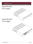
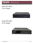
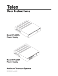
Telex® User Instructions Model PS2000L Power Supply Audiocom ® Intercom Systems ® FCC Statement This equipment uses, and can radiate radio frequency energy that may cause interference to radio communications if not installed in accordance with this manual. The equipment has been tested and found to comply with the limits of a Class A computing device pursuant to Subpart J, Part 15 of FCC Rules which are designed to provide reasonable protection against such interference when operated in a commercial environment. Operation of this equipment in a residential area may cause interference which the user (at his own expense) will be required to correct. This product meets Electromagnetic Compatibility Directive 89/336/EEC. Introduction. Thank you for purchasing the Audiocom PS2000L Power Supply. We hope that this power supply, used together with your Audiocom User Stations, will satisfy your intercommunication requirements for many years to come. To get the most out of your new power supply, please take a few moments to look through this booklet before using the PS2000L for the first time. 2 Table of Contents Description . . . . . . . . . . . . . 4 Installation . . . . . . . . . . . . . 6 Unpacking . . . . . . . . . . . . 6 Configuration Switches . . . . . . . . . . 6 . . . . . . . . 7 Intercom Channel Connections Power-Up Check . Specifications . . . . . . . . . . . . 10 . . . . . . . . . . 11 . . . . . . . 12 Factory Service and Parts Information 3 Audiocom® Description The PS2000L is a versatile power supply that can be used in a variety of Audiocom intercom system applications. It directly accepts any AC input power from 100 to 240 VAC, 50/60 Hz, and it can be configured to power two separate intercom channels or one large intercom channel with twice the intercom station capacity. Additionally, the PS2000L can be configured for compatibility with Clear-Com* Intercom Systems. The PS2000L can be rack mounted or used on a desktop. For rack mounting, optional hardware is required. For desktop use, four non-marring rubber feet are supplied. Figure 1. PS2000L Reference View (See following numbered descriptions) 1. Combine / Isolate Switch: This pushbutton switch lets you combine the audio signals of the two channels to create a single audio channel where all users can intercommunicate. Or, you can isolate each channel to create two groups of completely independent users. * Brand names mentioned are the property of their respective companies. 4 2. Channel Status Indicators and Reset Pushbutton: The indicators are green for normal operation and red when there is an overload or short circuit. The Reset pushbutton restores normal operation after the short-circuit or overload has been located and fixed. 3. Universal AC Power Input: The PS2000L accepts any input power in the range of 100-240 VAC, 50/60 Hz. 4. Intercom Channel Connectors: When the Combine / Isolate switch is set to the Isolate position, each channel connector is powered separately and has completely separate intercom audio. When the Combine / Isolate switch is set to the Combine position, each channel is still powered separately, but the audio signals are combined so that all users on both channels can intercommunicate. 5. Audiocom / Clear-Com Selector Switch (Figure 2): This selector switch sets the PS2000L for compatibility with either Audiocom (BALANCED) or Clear-Com (UNBALANCED). Compatibility includes channel connector pin-outs, channel power requirements, and call signaling requirements. The PS2000L is shipped with this switch in the Audiocom position. 5 Audiocom® Installation Unpacking The package contains the following items. Contact the shipper or your Audiocom dealer immediately if anything is damaged or missing. Detach and fill out the registration card and return it to Telex to properly register your PS2000L. Quantity 1 1 1 4 1 Description PS2000L Power Supply Warranty and registration card User Manual Rubber feet (install for desktop use of the PS2000L) Power cord Configuration Switches WARNING The following instructions are for use by qualified personnel only. To avoid electric shock, do not remove the cover unless you are qualified to do so. AVERTISSEMENT Les instructions qui suivent s'adressent uniquement a un technicien qualifie. Pour evite des chocs electriques, ne pas ouvrir le boitier, a moins d'y entre habilite. The Audiocom / Clear-Com switch (S200) is factory set for use with Audiocom intercom stations. Before using the PS2000L with Clear-Com, remove the top cover and change the setting as shown in Figure 2. The top cover is secured by five screws on the top and three screws on each side. The Combine / Isolate switch position may be changed at any time by inserting a pen point or other small object through the front panel. When the switch is in the Combine position, all users on both channels may intercommunicate. When the switch is set to the Isolate position, channels 1 and 2 cannot intercommunicate. 6 Figure 2. Audiocom / Clear-Com Selector Switch (Top Cover Removed) Intercom Channel Connections Channel Capacity: When connecting intercom stations to the PS2000L, determine the total current for all stations on each channel. The total per channel should not exceed 2A. If you exceed this limit, the PS2000L will provide an overload indication. Note that if you are using DC wallpacks with any intercom stations, you do not need to add the current consumption of those stations to the total current. Clear-Com Applications: Refer to your Clear-Com system documentation for cable wiring and connection details. After connecting the components, perform the powerup check on page 10. Audiocom Connections: Cable wiring details are shown in Figure 3. Some typical applications are shown in Figures 4 and 5. After connecting the components, perform the power-up check on page 10. 7 Audiocom® TYPICAL 1-CHANNEL CABLE WIRING 3 2 Pair 1 3 2 1 Pair 2 1 (Both wires) Shield Shield Cable Type: 22AWG Stranded, 2-Pair Twisted-wire, with Shield Connector Type: 3-Pin XLR Audio (Neutrik or Switchcraft)* Pin 1: Common Denotes twisted pair. Pin 2: Channel Audio / Power Pin 3: Channel Audio / Power Denotes shield. Shield: Earth ground TYPICAL 2-CHANNEL CABLE WIRING 4 3 6 5 4 3 6 5 Pair 1 Pair 2 1 1 (Both wires) Pair 3 Shield Shield Cable Type: 22AWG Stranded, 3-Pair Twisted-wire, with Shield Connector Type: 6-Pin XLR Audio (Neutrik only, not compatible with 6-pin Switchcraft)* Pin 1: Channel 1 & 2 Common Pin 2: No connection Denotes twisted pair. Pin 3: Channel 1 Audio / Power Pin 4: Channel 1 Audio / Power Denotes shield. Pin 5: Channel 2 Audio / Power Pin 6: Channel 2 Audio / Power Shield: Earth ground 3 Ch1 2 1 Case “Y” CABLE WIRING Pair 1 Pair 2 3 Ch2 2 1 Shield Pair 3 4 3 6 5 1 (Both wires) Shield Use second drain wire if available, or add an extra section of wire. * Standard cables are generally constructed using a male connector at one end and a female connector at the other end. This allows several cables to be interconnected to create longer cable runs. Audiocom master stations, speaker stations and belt packs also typically provide both a male and female Neutrik connector for each intercom channel. This permits loop-through connection of several intercom stations using the standard cables. Audiocom power supplies use a 3-pin male Neutrik connector for each channel. Audiocom wallplates use male Neutrik connectors. Figure 3. Cable Wiring Diagrams for Audiocom Applications 8 Figure 4. Typical connections using a single PS2000L Power Supply to power two channels. 9 Audiocom® Figure 5. Using two PS2000L Power Supplies to provide a greater capacity on each channel. Power-Up Check 1. ☞ Plug in any DC wallpacks that are being used with individual intercom stations. If you plug in DC wallpacks after applying power to the PS2000L, you may get an overload indication at the PS2000L. This is because the stations that are being powered by wallpacks will draw current from the PS2000L until their own DC supplies are connected. 2. Plug in the AC power cords for any connected PS2000L Power Supplies. The channel status indicators should be green. 3. If a channel status indicator turns red during operation, try correcting the problem by pressing the reset button on the front of the PS2000L. If the problem persists, unplug the PS2000L and locate the short or overload that is causing the problem. 10 Specifications General Input Power Requirements: 100 to 240 VAC, 50 / 60 Hz Output Power (each channel) 21 ± 1 VDC, 2A Dimensions: 1.75" (44.5 mm) high x 8.25" (209.5 mm) wide x 10.31" (261.9 mm) deep Weight: approximately 2.5 lb (1.13 kg) Environmental Requirements: Storage: -20°C to 80°C; 0% to 95% humidity, non-condensing Operating: 0°C to 50°C; 0% to 95% humidity, non-condensing Intercom Channels General Connector Type: One XLR-3M audio connector for each channel. Pin-out depends on setting of internal switch S200 for balanced or unbalanced operation as defined below. Balanced Mode (S200 set to BAL position) Line Terminating Impedance: 300 ohms ± 10% Connector Pin-out Pin 1 Common (audio and DC return) Pin 2 Full-duplex, balanced intercom audio and +24 VDC output Pin 3 Full-duplex, balanced intercom audio and +24 VDC output Unbalanced Mode (S200 set to UNBAL position) Line Terminating Impedance: 150 ohms ± 5% Connector Pin-out Pin 1 Common (audio and DC return) Pin 2 +24 VDC output Pin 3 Full-duplex, unbalanced Intercom audio high Approvals UL, CUL, CE 11 Audiocom® Factory Service and Parts Information When returning equipment for repair include your return address, telephone number and proof of date of purchase, along with a description of the problem.* The address for Audiocom equipment returns and parts information is: Service Department Telex Communications, Inc. West 1st Street Blue Earth, Minnesota 56013 U.S.A. Telephone: (507) 526-3205 (Collect calls not accepted) Warranty Repairs - If in warranty, no charge will be made for the repairs. Equipment returned for warranty repair must be sent prepaid and will be returned prepaid. Non-Warranty Repairs - Equipment that is not under warranty must be sent prepaid to Telex. If requested, an estimate of repair costs will be issued prior to service. After your approval and completion of the repairs, the equipment will be returned on a collect basis. Collect charges may be avoided by sending a signed check for payment in full along with your signed estimate approval form (shipping charges are included in the estimate). * For sales / technical support and system design contact: Pro Audio Sales Department Telex Communications, Inc. 9600 Aldrich Avenue South Minneapolis, Minnesota 55420 U.S.A. Telephone: (612) 884-4051 (Collect calls not accepted) 12 Notes: 13 Audiocom® Notes: 14 Notes: 15 ® TELEX COMMUNICATIONS, INC. 9350-7333-015 Rev. A 3 , 8/97 9600 Aldrich Ave. So., Minneapolis, MN 55420 U.S.A.