1
OPERATOR'S
MANUAL
Model 8752, 8756, & 8757
Soft Serve Freezers
Original Operating Instructions
028752- M
8/99 (Original Publication)
(Updated 8/14/14)
Complete this page for quick reference when service is required:
Taylor Distributor:
Address:
Phone:
Service:
Parts:
Date of Installation:
Information found on the data label:
Model Number:
Serial Number:
Electrical Specs:
Voltage
Cycle
Phase
Maximum Fuse Size:
Amps
Minimum Wire Ampacity:
Amps
Part Number:
E 1999 Carrier Commercial Refrigeration, Inc.
028752- M
Any unauthorized reproduction, disclosure, or distribution of copies by any person of any portion of this work may be
a violation of Copyright Law of the United States of America and other countries, could result in the awarding of Statutory
Damages of up to $250,000 (17 USC 504) for infringement, and may result in further civil and criminal penalties.
All rights reserved.
Taylor Company
a division of Carrier Commercial Refrigeration, Inc.
750 N. Blackhawk Blvd.
Rockton, IL 61072
Table of Contents
Section 1
To the Installer . . . . . . . . . . . . . . . . . . . . . . . . . . . . . . . . . . . . . . . . . . . .
1
Section 2
To the Operator . . . . . . . . . . . . . . . . . . . . . . . . . . . . . . . . . . . . . . . . . . .
4
Section 3
Safety . . . . . . . . . . . . . . . . . . . . . . . . . . . . . . . . . . . . . . . . . . . . . . . . . . . .
5
Section 4
Operator Parts Identification . . . . . . . . . . . . . . . . . . . . . . . . . . . . . . .
7
Model 8752 . . . . . . . . . . . . . . . . . . . . . . . . . . . . . . . . . . . . . . . . . . . . . . . . . . . . . . . . . .
7
8752 Beater Door Assembly . . . . . . . . . . . . . . . . . . . . . . . . . . . . . . . . . . . . . . . . . . . .
9
Model 8756 . . . . . . . . . . . . . . . . . . . . . . . . . . . . . . . . . . . . . . . . . . . . . . . . . . . . . . . . . .
11
Model 8757 . . . . . . . . . . . . . . . . . . . . . . . . . . . . . . . . . . . . . . . . . . . . . . . . . . . . . . . . . .
13
8756 & 8757 Beater Door Assembly . . . . . . . . . . . . . . . . . . . . . . . . . . . . . . . . . . . . .
15
Accessories . . . . . . . . . . . . . . . . . . . . . . . . . . . . . . . . . . . . . . . . . . . . . . . . . . . . . . . . . .
16
Section 5
Important: To the Operator . . . . . . . . . . . . . . . . . . . . . . . . . . . . . . . . .
17
Symbol Definitions . . . . . . . . . . . . . . . . . . . . . . . . . . . . . . . . . . . . . . . . . . . . . . . . . . . .
18
Power Switch . . . . . . . . . . . . . . . . . . . . . . . . . . . . . . . . . . . . . . . . . . . . . . . . . . . . . . . . .
18
Indicator Lights - MIX LOW and MIX OUT . . . . . . . . . . . . . . . . . . . . . . . . . . . . . . . .
18
Reset Button . . . . . . . . . . . . . . . . . . . . . . . . . . . . . . . . . . . . . . . . . . . . . . . . . . . . . . . . .
18
SOFTECH Control Operation . . . . . . . . . . . . . . . . . . . . . . . . . . . . . . . . . . . . . . . . . . .
18
MIX REF . . . . . . . . . . . . . . . . . . . . . . . . . . . . . . . . . . . . . . . . . . . . . . . . . . . . . . . . . . . . .
18
Standby . . . . . . . . . . . . . . . . . . . . . . . . . . . . . . . . . . . . . . . . . . . . . . . . . . . . . . . . . . . . . .
19
Wash . . . . . . . . . . . . . . . . . . . . . . . . . . . . . . . . . . . . . . . . . . . . . . . . . . . . . . . . . . . . . . . .
19
Auto . . . . . . . . . . . . . . . . . . . . . . . . . . . . . . . . . . . . . . . . . . . . . . . . . . . . . . . . . . . . . . . . .
19
Pump . . . . . . . . . . . . . . . . . . . . . . . . . . . . . . . . . . . . . . . . . . . . . . . . . . . . . . . . . . . . . . . .
19
Adjustable Draw Handle . . . . . . . . . . . . . . . . . . . . . . . . . . . . . . . . . . . . . . . . . . . . . . .
19
Section 6
Operating Procedures . . . . . . . . . . . . . . . . . . . . . . . . . . . . . . . . . . . . .
20
Prior to Set- Up (Model 8757) . . . . . . . . . . . . . . . . . . . . . . . . . . . . . . . . . . . . . . . . . . .
20
Assembly . . . . . . . . . . . . . . . . . . . . . . . . . . . . . . . . . . . . . . . . . . . . . . . . . . . . . . . . . . . .
20
Air/Mix Pump Assembly . . . . . . . . . . . . . . . . . . . . . . . . . . . . . . . . . . . . . . . . . . . . . . . .
24
Air/Mix Pump Assembly Exploded View . . . . . . . . . . . . . . . . . . . . . . . . . . . . . . . . . .
28
Sanitizing . . . . . . . . . . . . . . . . . . . . . . . . . . . . . . . . . . . . . . . . . . . . . . . . . . . . . . . . . . . .
29
Priming . . . . . . . . . . . . . . . . . . . . . . . . . . . . . . . . . . . . . . . . . . . . . . . . . . . . . . . . . . . . . .
31
Closing Procedure . . . . . . . . . . . . . . . . . . . . . . . . . . . . . . . . . . . . . . . . . . . . . . . . . . . .
32
Draining Product From the Freezing Cylinder . . . . . . . . . . . . . . . . . . . . . . . . . . . . .
32
Table of Contents
Models 8752, 8756, & 8757
Table of Contents - Page 2
Rinsing . . . . . . . . . . . . . . . . . . . . . . . . . . . . . . . . . . . . . . . . . . . . . . . . . . . . . . . . . . . . . .
33
Cleaning . . . . . . . . . . . . . . . . . . . . . . . . . . . . . . . . . . . . . . . . . . . . . . . . . . . . . . . . . . . . .
33
Disassembly . . . . . . . . . . . . . . . . . . . . . . . . . . . . . . . . . . . . . . . . . . . . . . . . . . . . . . . . . .
34
Brush Cleaning . . . . . . . . . . . . . . . . . . . . . . . . . . . . . . . . . . . . . . . . . . . . . . . . . . . . . . .
34
Check Topping Pump Temperature and Volume - Model 8757 . . . . . . . . . . . . . .
35
Section 7
Important: Operator Checklist . . . . . . . . . . . . . . . . . . . . . . . . . . . . . .
36
During Cleaning and Sanitizing . . . . . . . . . . . . . . . . . . . . . . . . . . . . . . . . . . . . . . . . .
36
Troubleshooting Bacterial Count . . . . . . . . . . . . . . . . . . . . . . . . . . . . . . . . . . . . . . . .
36
Regular Maintenance Checks . . . . . . . . . . . . . . . . . . . . . . . . . . . . . . . . . . . . . . . . . . .
36
The Air/Mix Pump . . . . . . . . . . . . . . . . . . . . . . . . . . . . . . . . . . . . . . . . . . . . . . . . . . . . .
37
Winter Storage . . . . . . . . . . . . . . . . . . . . . . . . . . . . . . . . . . . . . . . . . . . . . . . . . . . . . . . .
37
Section 8
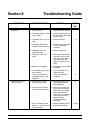
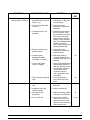
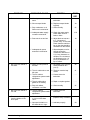
Troubleshooting Guide . . . . . . . . . . . . . . . . . . . . . . . . . . . . . . . . . . . .
38
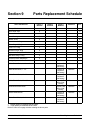
Section 9
Parts Replacement Schedule . . . . . . . . . . . . . . . . . . . . . . . . . . . . . . .
43
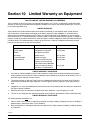
Section 10
Limited Warranty on Equipment . . . . . . . . . . . . . . . . . . . . . . . . . . . .
44
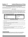
Section 11
Limited Warranty on Parts . . . . . . . . . . . . . . . . . . . . . . . . . . . . . . . . .
46
Section 12
Parts List . . . . . . . . . . . . . . . . . . . . . . . . . . . . . . . . . . . . . . . . . . . . . . . . .
49
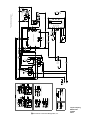
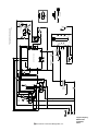
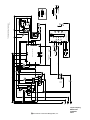
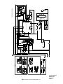
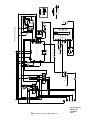
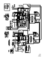
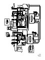
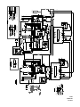
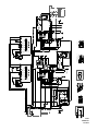
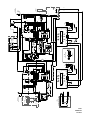
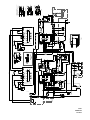
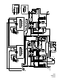
Wiring Diagrams . . . . . . . . . . . . . . . . . . . . . . . . . . . . . . . . . . . . . . . . . . . . . . . . . . . . . .
61
Note: Continuing research results in steady improvements; therefore, information
in this manual is subject to change without notice.
Note: Only instructions originating from the factory or its authorized translation
representative(s) are considered to be the original set of instructions.
E 1999 Carrier Commercial Refrigeration, Inc. (Original Publication)
(Updated August, 2014)
028752- M
Any unauthorized reproduction, disclosure, or distribution of copies by any person of any portion of this work
may be a violation of Copyright Law of the United States of America and other countries, could result in the
awarding of Statutory Damages of up to $250,000 (17 USC 504) for infringement, and may result in further
civil and criminal penalties. All rights reserved.
Taylor Company
a division of Carrier Commercial Refrigeration, Inc.
750 N. Blackhawk Blvd.
Rockton, IL 61072
Table of Contents
Models 8752, 8756, & 8757
Section 1
To the Installer
Site Preparation
The following information has been included in the
manual as safety and regulatory guidelines. For
complete installation instructions, please see the
Installation Checklist.
Review the area where the unit will be installed before
uncrating the unit. Make sure all possible hazards to
the user or equipment have been addressed.
Installer Safety
In all areas of the world, equipment should be
installed in accordance with existing local codes.
Please contact your local authorities if you have any
questions.
Air Cooled Units
Care should be taken to ensure that all basic safety
practices are followed during the installation and
servicing activities related to the installation and
service of Taylor equipment.
Air cooled units require a minimum of 3” (76 mm) of
clearance around all sides of the freezer and 12” (305
mm) on top to allow for adequate air flow across the
condenser(s). Failure to allow adequate clearance can
reduce the refrigeration capacity of the freezer and
possibly cause permanent damage to the compressor.
S
S
S
S
DO NOT obstruct air intake and discharge openings:
Only authorized Taylor service personnel
should perform installation and repairs on the
equipment.
Authorized service personnel should consult
OSHA Standard 29CFRI910.147 or the
applicable code of the local area for the
industry
standards
on lockout/tagout
procedures before beginning any installation
or repairs.
Authorized service personnel must ensure
that the proper PPE is available and worn
when required during installation and service.
Authorized service personnel must remove all
metal jewelry, rings, and watches before
working on electrical equipment.
For Indoor Use Only: This unit is designed to operate
indoors, under normal ambient temperatures of
70_-75_F (21_-24_C). The freezer has successfully
performed in high ambient temperatures of
104_(40_C) at reduced capacities.
This unit must NOT be installed in an area
where a water jet or hose can be used. NEVER use a
water jet or hose to rinse or clean the unit. Failure to
follow this instruction may result in electrocution.
The main power supply(s) to the freezer must
be disconnected prior to performing any repairs.
Failure to follow this instruction may result in personal
injury or death from electrical shock or hazardous
moving parts as well as poor performance or damage
to the equipment.
This unit must be installed on a level surface
to avoid the hazard of tipping. Extreme care should be
taken in moving this equipment for any reason. Two or
more persons are required to safely move this unit.
Failure to comply may result in personal injury or
equipment damage.
Note: All repairs must be performed by an
authorized Taylor Service Technician.
Uncrate the unit and inspect it for damage. Report any
damage to your Taylor Distributor.
This piece of equipment is made in the USA and has
USA sizes of hardware. All metric conversions are
approximate and vary in size.
This unit has many sharp edges that can
cause severe injuries.
131210
Models 8752, 8756, 8757
1
To the Installer
Water Connections
(Water Cooled Units Only)
Each unit requires one power supply for each data
label on the unit. Check the data label(s) on the freezer
for branch circuit overcurrent protection or fuse, circuit
ampacity and other electrical specifications. Refer to
the wiring diagram provided inside of the electrical box,
for proper power connections.
An adequate cold water supply must be provided with
a hand shut- off valve. On the underside rear of the
base pan, two 3/8” I.P.S. (for single- head units) or two
1/2” I.P.S. (for double- head units) water connections
for inlet and outlet have been provided for easy
hook- up. 1/2” inside diameter water lines should be
connected to the machine. (Flexible lines are
recommended, if local codes permit.) Depending on
local water conditions, it may be advisable to install a
water strainer to prevent foreign substances from
clogging the automatic water valve. There will be only
one water “in” and one water “out” connection for both
single- head and double- head units. DO NOT install a
hand shut- off valve on the water “out” line! Water
should always flow in this order: first, through the
automatic water valve; second, through the
condenser; and third, through the outlet fitting to an
open trap drain.
CAUTION: THIS EQUIPMENT MUST BE
PROPERLY GROUNDED! FAILURE TO DO SO
CAN RESULT IN SEVERE PERSONAL INJURY
FROM ELECTRICAL SHOCK!
DO NOT operate this freezer with larger fuses
than specified on the unit data label. Failure to follow
this instruction may result in electrocution or damage
to the machine.
This unit is provided with an equipotential
grounding lug that is to be properly attached to the rear
of the frame by the authorized installer. The installation
location is marked by the equipotential bonding
symbol (5021 of IEC 60417-1) on both the removable
panel and the equipment’s frame.
A back flow prevention device is required
on the incoming water connection side. Please
refer to the applicable National, State, and local codes
for determining the proper configuration.
Electrical Connections
Stationary appliances which are not equipped
with a power cord and a plug or another device to
disconnect the appliance from the power source must
have an all-pole disconnecting device with a contact
gap of at least 3 mm installed in the external
installation.
In the United States, this equipment is intended to be
installed in accordance with the National Electrical
Code (NEC), ANSI/NFPA 70-1987. The purpose of the
NEC code is the practical safeguarding of persons and
property from hazards arising from the use of
electricity. This code contains provisions considered
necessary for safety. In all other areas of the world,
equipment should be installed in accordance with the
existing local codes. Please contact your local
authorities.
Appliances that are permanently connected to
fixed wiring and for which leakage currents may
exceed 10 mA, particularly when disconnected or not
used for long periods, or during initial installation, shall
have protective devices such as a GFI, to protect
against the leakage of current, installed by the
authorized personnel to the local codes.
FOLLOW YOUR LOCAL ELECTRICAL CODES!
101122
To the Installer
2
Models 8752, 8756, 8757
Refrigerant
Supply cords used with this unit shall be
oil-resistant, sheathed flexible cable not lighter than
ordinary polychloroprene or other equivalent synthetic
elastomer-sheathed cord (Code designation 60245
IEC 57) installed with the proper cord anchorage to
relieve conductors from strain, including twisting, at
the terminals and protect the insulation of the
conductors from abrasion.
In consideration of our environment, Taylor
proudly uses only earth friendly HFC refrigerants. The
HFC refrigerant used in this unit is R404A. This
refrigerant is generally considered non-toxic and
non-flammable, with an Ozone Depleting Potential
(ODP) of zero (0).
However, any gas under pressure is potentially
hazardous and must be handled with caution.
If the supply cord is damaged, it must be replaced by
the manufacturer, its service agent, or similarly
qualified person, in order to avoid a hazard.
NEVER fill any refrigerant cylinder completely with
liquid. Filling the cylinder to approximately 80% will
allow for normal expansion.
Beater Rotation
Use only R404A refrigerant that conforms to
the AHRI standard 700 specification. The use of any
other refrigerant may expose users and operators to
unexpected safety hazards.
Beater rotation must be clockwise as viewed
looking into the freezing cylinder.
Refrigerant liquid sprayed onto the skin may
cause serious damage to tissue. Keep eyes and skin
protected. If refrigerant burns should occur, flush
immediately with cold water. If burns are severe, apply
ice packs and contact a physician immediately.
Note: The following procedures should be
performed by a trained service technician.
To correct the rotation on a three- phase unit,
interchange any two incoming power supply lines at
freezer main terminal block only.
Taylor reminds technicians to be cautious of
government laws regarding refrigerant recovery,
recycling, and reclaiming systems. If you have any
questions regarding these laws, please contact the
factory Service Department.
To correct rotation on a single- phase unit, change the
leads inside the beater motor. (Follow the diagram
printed on the motor.)
Electrical connections are made directly to the
terminal block provided in the splice box which is
mounted on the base pan on the right side of the
freezer for the Model 8752 and located in the splice
boxes which are mounted mid- level on the frame
channel on the right and left sides for the Models 8756
and 8757.
WARNING: R404A refrigerant used in
conjunction with polyolester oils is extremely moisture
absorbent. When opening a refrigeration system, the
maximum time the system is open must not exceed 15
minutes. Cap all open tubing to prevent humid air or
water from being absorbed by the oil.
130819
Models 8752, 8756, 8757
3
To the Installer
Section 2
To the Operator
The freezer you have purchased has been carefully
engineered and manufactured to give you dependable
operation. The Taylor Models 8752, 8756, and 8757
are highly sophisticated pieces of equipment, and
when properly operated and cared for, will produce a
consistent quality product. Like all mechanical
products, they will require cleaning and maintenance.
A minimum amount of care and attention is necessary
if the operating procedures outlined in this manual are
followed closely.
legislation in effect after August 13, 2005. Therefore,
it must be collected separately after its use is
completed, and cannot be disposed as unsorted
municipal waste.
This Operator’s Manual should be read
before operating or performing any maintenance on
your equipment.
Compressor Warranty Disclaimer
The user is responsible for returning the product to the
appropriate collection facility, as specified by your local
code.
For additional information regarding applicable local
laws, please contact the municipal facility and/or local
distributor.
The refrigeration compressor(s) on this unit are
warranted for the term stated in the Limited Warranty
section in this manual. However, due to the Montreal
Protocol and the U.S. Clean Air Act Amendments of
1990, many new refrigerants are being tested and
developed, thus seeking their way into the service
industry. Some of these new refrigerants are being
advertised as drop- in replacements for numerous
applications. It should be noted that in the event of
ordinary service to this unit’s refrigeration system,
only the refrigerant specified on the affixed data
label should be used. The unauthorized use of
alternate refrigerants will void your Taylor compressor
warranty. It is the unit owner’s responsibility to make
this fact known to any technician he employs.
Your freezer will NOT eventually compensate and
correct for any errors during the set- up or filling
operations. Thus, the initial assembly and priming
procedures are of extreme importance. It is strongly
recommended that all personnel responsible for the
equipment’s operation study these procedures
together in order to be properly trained and to make
sure that no misunderstandings exist.
In the event you should require technical assistance,
please contact your local authorized Taylor Distributor.
Note: Your Taylor warranty is valid only if the parts are
authorized Taylor parts, purchased from the local
authorized Taylor Distributor, and only if all required
service work is provided by an authorized Taylor
service technician. Taylor reserves the right to deny
warranty claims on units or parts if non- Taylor
approved parts or incorrect refrigerant were installed
in the unit, system modifications were performed
beyond factory recommendations, or it is determined
that the failure was caused by abuse, misuse, neglect,
or failure to follow all operating instructions. For full
details of your Taylor Warranty, please see the Limited
Warranty section in this manual.
It should also be noted that Taylor does not warrant the
refrigerant used in its equipment. For example, if the
refrigerant is lost during the course of ordinary service
to this machine, Taylor has no obligation to either
supply or provide its replacement either at billable or
unbillable terms. Taylor does have the obligation to
recommend a suitable replacement if the original
refrigerant is banned, obsoleted, or no longer available
during the five year warranty of the compressor.
The Taylor Company will continue to monitor the
industry and test new alternates as they are being
developed. Should a new alternate prove, through our
testing, that it would be accepted as a drop- in
replacement, then the above disclaimer would
become null and void. To find out the current status of
an alternate refrigerant as it relates to your
compressor warranty, call the local Taylor Distributor
or the Taylor Factory. Be prepared to provide the
Model/Serial Number of the unit in question.
Note: Constant research results in steady
improvements; therefore, information in this
manual is subject to change without notice.
If the crossed out wheeled bin symbol is
affixed to this product, it signifies that this product is
compliant with the EU Directive as well as other similar
131210
To the Operator
4
Models 8752, 8756, 8757
Section 3
Safety
We, at Taylor Company, are concerned about the
safety of the operator when he or she comes in contact
with the freezer and its parts. Taylor has gone to
extreme efforts to design and manufacture built- in
safety features to protect both you and the service
technician. As an example, warning labels have been
attached to the freezer to further point out safety
precautions to the operator.
DO NOT use a water jet to clean or rinse the
freezer. Failure to follow these instructions may result
in serious electrical shock.
S
IMPORTANT - Failure to adhere to the
following safety precautions may result in severe
personal injury or death. Failure to comply with
these warnings may damage the machine and its
components. Component damage will result in
part replacement expense and service repair
expense.
S
S
S
S
DO NOT operate the freezer without reading
this Operator Manual. Failure to follow this instruction
may result in equipment damage, poor freezer
performance, health hazards, or personal injury.
S
This appliance is to be used only by trained
personnel. It is not intended for use by children or
people with reduced physical, sensory, or mental
capabilities, or lack of experience and knowledge,
unless given supervision or instruction concerning the
use of the appliance by a person responsible for their
safety. Children should be supervised to ensure that
they do not play with the appliance.
S
S
This unit is provided with an equipotential
grounding lug that is to be properly attached to the rear
of the frame by the authorized installer. The installation
location is marked by the equipotential bonding
symbol (5021 of IEC 60417-1) on both the removable
panel and the equipment’s frame.
DO NOT operate the freezer unless it is
properly grounded.
DO NOT operate the freezer with larger fuses
than specified on the freezer data label.
All repairs must be performed by an
authorized Taylor service technician.
The main power supplies to the machine must
be disconnected prior to performing any
repairs.
For Cord Connected Units: Only Taylor
authorized service technicians or licensed
electricians may install a plug or replacement
cord on these units.
Stationary appliances which are not equipped
with a power cord and a plug or another device
to disconnect the appliance from the power
source, must have an all-pole disconnecting
device with a contact gap of at least 3 mm
installed in the external installation.
Stationary appliances which are not equipped
with a power cord and a plug or another device
to disconnect the appliance from the power
source must have an all-pole disconnecting
device with a contact gap of at least 3 mm
installed in the external installation.
Appliances that are permanently connected to
fixed wiring and for which leakage currents
may exceed 10 mA, particularly when
disconnected or not used for long periods, or
during initial installation, shall have protective
devices such as a GFI, to protect against the
leakage of current, installed by the authorized
personnel to the local codes.
130211
Models 8752, 8756, 8757
5
Safety
S
Supply cords used with this unit shall be
oil-resistant, sheathed flexible cable not
lighter than ordinary polychloroprene or other
equivalent synthetic elastomer-sheathed cord
(Code designation 60245 IEC 57) installed
with the proper cord anchorage to relieve
conductors from strain, including twisting, at
the terminals and protect the insulation of the
conductors from abrasion.
Access to the service area of the unit is
restricted to persons having knowledge and practical
experience with the appliance, in particular as far as
safety and hygiene are concerned.
Cleaning and sanitizing schedules are
governed by your state or local regulatory agencies
and must be followed accordingly. Please refer to the
cleaning section of this manual for the proper
procedure to clean this unit.
If the supply cord is damaged, it must be
replaced by the manufacturer, its service
agent, or similarly qualified person, in order to
avoid a hazard.
Failure to follow these instructions may result in
electrocution. Contact your local authorized Taylor
Distributor for service.
S
S
S
This machine is designed to maintain product
temperature under 41_F (5_C). Any product being
added to this machine must be below 41_F (5_C).
Failure to follow this instruction may result in health
hazards and poor freezer performance.
DO NOT allow untrained personnel to operate
this machine.
DO NOT operate the freezer unless all service
panels and access doors are restrained with
screws.
DO NOT remove any internal operating parts
(example: freezer door, beater, scraper
blades, etc.) unless all control switches are in
the OFF position.
DO NOT run the unit without product. Failure to follow
this instruction can result in damage to the unit.
DO NOT obstruct air intake and discharge openings:
Air cooled units require a minimum of 3” (76 mm) of
clearance around all sides of the freezer and 12” (305
mm) on top to allow for adequate air flow across the
condenser(s). Failure to allow adequate clearance can
reduce the refrigeration capacity of the freezer and
possibly cause permanent damage to the compressor.
Failure to follow these instructions may result in severe
personal injury from hazardous moving parts.
This unit has many sharp edges that can
cause severe injuries.
S
S
DO NOT put objects or fingers in the door
spout. This may contaminate the product and
cause severe personal injury from blade
contact.
USE EXTREME CAUTION when removing
the beater asssembly. The scraper blades are
very sharp.
For Indoor Use Only: This unit is designed to operate
indoors, under normal ambient temperatures of 70_ 75_F (21_ - 24_C). The freezer has successfully
performed in high ambient temperatures of
104_(40_C) at reduced capacities.
NOISE LEVEL: Airborne noise emission does not
exceed 78 dB(A) when measured at a distance of 1.0
meter from the surface of the machine and at a height
of 1.6 meters from the floor.
This freezer must be placed on a level
surface. Failure to comply may result in personal injury
or equipment damage.
130819
Safety
6
Models 8752, 8756, 8757
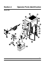
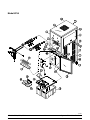
Section 4
Operator Parts Identification
Model 8752
130117
Models 8752, 8756, 8757
7
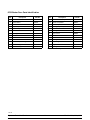
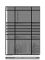
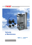
Operator Parts Identification
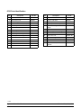
8752 Parts Identification
Item
Description
Part No.
Item
Description
Part No.
1
Panel A.- Front
X22997
16
Funnel- Mix
036637
2
Stud- Nose Cone
022822
17
Cover A.- Mix Tank
X38726
3
Bolt- Carriage
012347
18
Tray- Drip 16- 7/8 x 5- 1/8
020157
4
Panel A.- Lower Side (R & L)
X23956
19
Shield- Splash 23” Long
022765
5
Panel- Upper Side Left
028599
20
038827
6
Hood
050464
Cover- Mix Storage- Center
Single
7
Panel- Upper Rear
022074
21
Trim- Rear Corner
022071
8
Panel- Lower Rear
025128
22
Trim A.- Upper Side Left/Right
X22423
9
Panel- Upper Side Right
028600
23
Trim A.- Shelf
X20426
10
Pan- Drip 11- 5/8” Long
027503
24
Trim- Front- Left
024824- SP
11
Caster- Swivel 3/4- 10, 3” Wheel
021279
25
Trim- Front- Right
024825
12
Gasket- Cabinet Mix Door
020134
26
Trim- Bottom Mix Door
024974
13
Probe A.- Mix
X35981
27
Trim- Mix Door
024976
14
Boot- Mix Cover
037200
28
030307
15
Tank- Mix
020275
Caster- 3” SWV 3/4- 10 Stem
w/Brake
111129
Operator Parts Identification
8
Models 8752, 8756, 8757
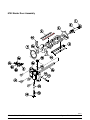
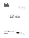
8752 Beater Door Assembly
130116
Models 8752, 8756, 8757
9
Operator Parts Identification
8752 Beater Door Parts Identification
Item
Description
Part No.
Item
Description
Part No.
1
Seal- Drive Shaft
032560
9
Handle A.- Draw- Adjustable
X55096
2
Shaft- Beater
032564
9a
Handle- Adjustable
028804
3
Beater A.- 3.4 Qt. 1 Pin
X46231
9b
Screw- Adjustment
055092
4
Clip- Scraper Blade
046236
9c
O- Ring (Adj. Screw)
015872
5
Blade- Scraper- Plastic
046235
9d
Nut- Jam 5/16- 24
029639- BLK
6
Kit A.- Beater- Front Shoes- Brg
X50350
10
O- Ring - 5/16 OD x .070 W
016272
*6a Bearing- Front
*See note
11
Pin A.- Pivot
X22820
*6b Shoe- Front Helix- Front
*See note
12
Nut- Stud
021508
*6c Shoe- Front Helix- Rear
*See note
13
Valve A.- Draw
X18303
7
Gasket- Door HT 4” Double
048926
14
O- Ring - 7/8 OD x .103 W
014402
8
Door A.- 1 Spout Long Baffle
X51531- 10
15
Cap- Design - 1.010” ID
014218
8a
Door A.- Magnet
X68625- 2
16
Plug- Prime
028805
8b
Baffle A.- Long 4”
X50882
17
O- Ring - 3/8 OD x .070 W
016137
*Order as X50350 only.
130116
Operator Parts Identification
10
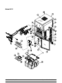
Models 8752, 8756, 8757
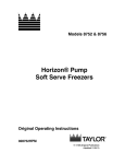
Model 8756
111129
Models 8752, 8756, 8757
11
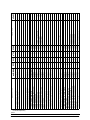
Operator Parts Identification
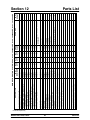
8756 Parts Identification
Item
Description
Part No.
Item
Description
Part No.
1
Panel A.- Front
X22879
16
Cover- Mix Tank
024590
2
Stud- Nose Cone
022822
17
Funnel- Mix
036637
3
Bolt- Carriage
012347
18
Tray- Drip 22- 7/8 x 5- 1/8
014533
4
Panel A.- Lower Side (R & L)
X23956
19
Shield- Splash 23” Long
022766
5
Panel- Upper Side Left
028599
20
Cover- Left Mix Storage
037138
6
Hood
048526
21
Cover- Right Mix Storage
037139
7
Panel- Upper Rear
022015
22
Trim- Corner- Left/Right
022013
8
Panel- Lower Rear
023598
23
Trim A.- Side Left/Right
X22424
9
Panel- Upper Side Right
028600
24
Trim A.- Shelf
X24813
10
Pan- Drip 17- 1/4” Long
027504
25
Trim- Front- Left
024824- SP
11
Caster- Swivel 3/4- 10, 3” Wheel
021279
26
Trim- Front- Right
024825
12
Gasket- Cabinet Mix Door
024629
27
Trim- Bottom Cabinet
024826
13
Probe A.- Mix (2)
X35981
28
Strip- Top Trim
024827
14
Boot- Mix Cover
037200
29
030307
15
Tank A.- Mix w/Decals
X38755
Caster- 3” Swv 3/4- 10 Stem
w/Brake
15a
Tank (only)
034928
111129
Operator Parts Identification
12
Models 8752, 8756, 8757
Model 8757
Models 8752, 8756, 8757
13
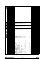
Operator Parts Identification
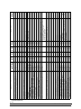
8757 Parts Identification
Item
Description
Part No.
Item
Description
Part No.
1
Panel A.- Front
X36711
16
Cover- Mix Tank
024590
2
Stud- Nose Cone
022822
17
Funnel- Mix
036637
3
Bolt- Carriage 1/4- 20 x 3/4
012347
18
Tray- Drip
014533
4
Panel A.- Lower Side- L/R
X36741
19
Shield- Splash 23” Long
022766
5
Panel- Upper Side Left
028599
20
Cover- Mix Storage Left
037138
6
Hood
048526
21
Cover- Mix Storage Right
037139
7
Panel- Upper Rear
042068
22
Trim- Rear Corner- Left/Right
036740
8
Panel- Lower Rear
042067
23
Trim A.- Side Left/Right
X22424
9
Panel- Upper Side Right
028600
24
Trim A.- Shelf
X36732
10
Pan- Drip
036232
25
Trim- Front- Left
024824- SP
11
Caster- Swivel 3/4- 10 ST
021279
26
Trim- Front- Right
024825
12
Gasket- Cabinet- Mix Door
024629
27
Trim- Bottom Cabinet
024826
13
Probe A.- Mix
X35981
28
Strip- Top Trim
024827
14
Boot- Mix Cover
037200
29
030307
15
Tank- Mix
X38755
Caster- 3” Swv 3/4- 10 Stem
w/Brake
15a
Tank (only)
034928
111129
Operator Parts Identification
14
Models 8752, 8756, 8757
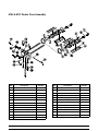
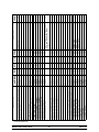
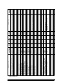
8756 & 8757 Beater Door Assembly
Item
Description
Part No.
Item
Description
1
Seal- Drive Shaft
032560
9c
2
Shaft- Beater
032564
9d
3
Beater A.- 3.4 Qt. 1 Pin
X46231
10
O- Ring - 5/16 OD x .070 W
016272
4
Clip- Scraper Blade
046236
11
Rod A.- Pivot
X22387
5
Blade- Scraper- Plastic
046235
12
Nut- Stud (Long)
034382
*6a
Bearing- Front
050348
13
Valve A.- Draw (3)
X18303
*6b
Shoe- Front Helix- Rear
050346
14
O- Ring - 7/8 OD x .103 W (6)
014402
*6c
Shoe- Front Helix- Front
050347
15
Cap- Design - 1.010” ID
014218
7
Gasket- Door 4” Double
048926
16
Nut- Stud (Short)
034383
8
Door A.- 3 Spout Long Baffle
X51532- 12
17
Rod A.- Pivot
X22388
9
Handle A.- Draw- Adj.
X33687
18
Plug- Prime (2)
028805
9a
Draw Handle- Adj.
028804
19
O- Ring - 3/8 OD x .070 W (4)
016137
9b
Screw- Adjustment
033662
Models 8752, 8756, 8757
O- Ring (Adj. Screw)
Part No.
Nut- Jam 5/16- 24
015872
029639- BLK
*Order Kit X50350
15
Operator Parts Identification
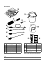
Accessories
Item
Description
Part No.
Item
Description
Part No.
1
Brush- Mix Pump Body
023316
8
Sanitizer- Kay- 5
*See note
2
Brush- Pressure Switch
027647
9
Pail- 10 Qt.
013163
3
Brush- Feed Tube
021101
4
Brush- Double Ended
013072
5
Brush- Rear Bearing
013071
6
Brush- Draw Valve
013073
7
Lubricant- Taylor 4 oz.
047518
Kit A.- Tune Up (Model 8752)
X49463- 15
10
Kit A.- Tune Up
(Models 8756 & 8757)
X49463- 2
11
Sanitizer- Stera Sheen- Green
(8752, 8756, 8757)
*See note
*Note: A sample container of sanitizer is sent with the
unit. For reorders, order Stera Sheen part no. 055492
(100 2 oz. packs) or Kay- 5 part no. 041082 (200 packs).
140814
Operator Parts Identification
16
Models 8752, 8756, 8757
Section 5
Important: To the Operator
Model 8752
Model 8756
Model 8757
Models 8752, 8756, 8757
17
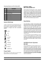
Important: To the Operator
Indicator Lights MIX LOW and MIX OUT
Parts Identification for 8752, 8756, & 8757
Item
1
2
3
4
5
6
7
8
9
10
Description
Power Switch (Toggle)
Reset Switch
Mix Refrigeration Control
STANDBY Key
WASH Key
AUTO Key
PUMP Key
Mix Low Indicator
Mix Out Indicator
Heater Switch
When the MIX LOW light begins to flash, it indicates
the mix tank has a low supply of mix and should be
refilled as soon as possible. When the MIX OUT light
begins to flash, it indicates the mix tank has been
almost completely exhausted and has an insufficient
supply of mix to operate the freezer. At this time, the
STANDBY and AUTO modes are locked out and the
freezer shuts down. To initiate the refrigeration
system, add mix to the tank and press the AUTO key.
The freezer will automatically begin operation.
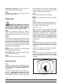
Reset Button
Symbol Definitions
The reset button is located in the decorative plate
above the SOFTECH controls. The reset protects the
beater motor from an overload condition. Should an
overload occur, the reset mechanism will trip. To
properly reset the freezer, press the AUTO key to
cancel the cycle. Turn the power switch to the OFF
position. Press the reset button firmly. Turn the power
switch to the ON position. Press the WASH key and
observe the freezer’s performance. Open the side
access panel to check if the beater motor is turning the
drive shaft in a clockwise (from operator end) direction
without binding.
To better communicate in the International arena, the
words on many of our operator switches and buttons
have symbols to indicate their functions. Your Taylor
equipment is designed with these International
symbols.
= AUTO
= ON
If it is turning properly, press the WASH key to cancel
the cycle. Press the AUTO key to resume normal
operation. (For the Models 8756 and 8757, press the
AUTO key on both sides to resume normal operation.)
If the freezer shuts down again, contact a service
technician.
= OFF
= MIX REF
= WASH
= PUMP
SOFTECH Control Operation
= STANDBY
MIX REF
= MIX LOW
When the MIX REF key is pressed, the light comes on,
indicating the mix cabinet refrigeration system is
operating. (For the Models 8756 and 8757, there are
two touch- tone panels, one for each freezing cylinder.
The mix refrigeration system is controlled by the MIX
REF key found on the left panel. By pressing the AUTO
key on either side of the freezer, the MIX REF function
is automatically turned on.) The MIX REF function
cannot be cancelled unless the AUTO or STANDBY
mode is cancelled first.
= MIX OUT
= HEATER ON
Power Switch
When placed in the ON position, the power switch
allows SOFTECH control panel operation.
Important: To the Operator
18
Models 8752, 8756, 8757
Standby
Pump
During long “No Sale” periods it becomes necessary
to warm the product in the freezing cylinder to
approximately 35_ to 40_F (1.7_to 4.4_C) to prevent
overbeating and product breakdown.
When the PUMP key is pressed, the light comes on
indicating the air/mix pump will operate as required.
When the STANDBY key is pressed, the light comes
on, indicating the CTR (Cylinder Temperature
Retention System) has been activated. In the
STANDBY mode, the WASH, PUMP, and AUTO
functions are automatically cancelled. The MIX REF
function is automatically locked in to maintain the mix
in the cabinet.
Note: An indicating light and an audible tone will
sound whenever a mode of operation has been
pressed. To cancel any function, press the PUMP key
again and the light and mode of operation will shut off.
To resume normal operation, press the AUTO key.
When the unit cycles off, the product in the freezing
cylinder will be at serving viscosity.
Adjustable Draw Handle
Wash
These units feature an adjustable draw handle to
provide the best portion control, giving a better,
consistent quality to your product and controlling
costs. The draw handle should be adjusted to provide
a flow rate of 5 to 7- 1/2 oz. of product by weight per
10 seconds. To increase the flow rate, turn the screw
counterclockwise. To decrease the flow rate, turn
the screw clockwise.
When the WASH key is pressed, the light comes on,
indicating beater motor operation. The STANDBY or
AUTO modes must be cancelled first to activate the
WASH mode.
Auto
In addition, for purposes of sanitizing and rinsing, the
flow rate can be increased by removing the pivot pin
and placing the restrictive bar on the top. When
drawing product, always have the restrictive bar on
the bottom.
When the AUTO key is pressed, the light comes on
indicating the main refrigeration system has been
activated. In the AUTO mode, the WASH or STANDBY
functions are automatically cancelled. The MIX REF
function is automatically locked in to maintain the mix
in the cabinet and the PUMP function is locked in to
allow air/mix pump operation as required.
IMPORTANT! When dispensing product, pull only
one draw handle at a time.
091030
Models 8752, 8756, 8757
19
Important: To the Operator
Section 6
Operating Procedures
The Model 8752 has been selected to show you the
pictured step- by- step operating procedures for both
models contained in this manual. These models, for all
practical purposes of operation, are the same.
Step 4
Fill the two heated and the two cold syrup jars with
topping. Replace the topping pumps in the heated
syrup jars. Sanitize two topping ladles and place them
in the cold syrup jars.
The size of the freezing cylinder(s) is 3.4 quarts (3.2
liters). The Model 8752 has one freezing cylinder and
the Models 8756 and 8757 have two freezing
cylinders. Mix is stored in the lower front refrigerated
compartment and is pumped up to the freezing
cylinder by an air/mix pump.
Duplicate the following procedures, where they apply,
for the second freezing cylinder on the Models 8756
and 8757.
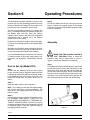
Assembly
We begin our instructions at the point where we enter
the store in the morning and find the parts laid out to
air dry from the previous night’s brush cleaning.
If you are disassembling the machine for the first time
or need information to get to this starting point in our
instructions, turn to page 34 , “Disassembly” and start
there.
MAKE SURE THE CONTROL SWITCH IS
IN THE “OFF” POSITION. Failure to follow this
instruction may result in electrocution or injury to
fingers or hands from hazardous moving parts.
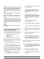
Prior to Set- Up (Model 8757)
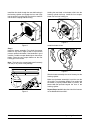
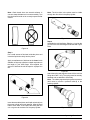
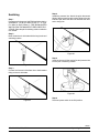
Step 1
To install the drive shaft, lubricate the groove and shaft
portion that comes in contact with the bearing on the
beater drive shaft. Slide the seal over the shaft and
groove until it snaps into place. DO NOT lubricate the
hex end of the drive shaft. Fill the inside portion of the
seal with1/4” more lubricant and evenly lubricate the
end of the seal that fits onto the rear shell bearing.
Step 1
Remove the two stainless syrup jars with topping
pumps, from the syrup rail. Check the water level in the
heated syrup topping well. Make sure the water is filled
to the indicating mark on the bottom of the well. (The
heated rail should have 32 ounces [946.2 ml.] of
water.)
Step 2
Place the heater switch in the ON position.
Note: This heating process will take approximately
two and one- half hours to reach temperature. The
water level in the topping wells must be checked at
least once daily.
Step 3
Prepare a pail of an approved 100 PPM sanitizing solution (examples: Stera SheenR or Kay- 5R). Use
WARM WATER ACCORDING TO THE MANUFACTURER’S SPECIFICATIONS. Sanitize the topping
pumps by placing the entire pump assembly in the pail
of sanitizing solution. Pump the solution through to
thoroughly sanitize the pump.
Figure 1
071017
Operating Procedures
20
Models 8752, 8756, 8757
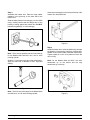
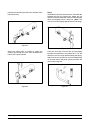
Install the drive shaft through the rear shell bearing in
the freezing cylinder and engage the hex end firmly
into the gear box coupling. Be sure the drive shaft fits
into the drive coupling without binding.
Holding the rear blade on the beater, slide it into the
freezing cylinder half way. Install the front scraper
blade over the front holding pin.
Figure 4
Figure 2
Install the beater shoes.
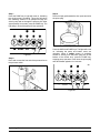
Step 2
Install the beater assembly. First check the scraper
blades for any nicks or signs of wear. If any nicks are
present, replace both blades. If the blades are in good
condition, install the scraper blade clips on the scraper
blades. Place the rear scraper blade over the rear
holding pin on the beater.
Note: The hole on the scraper blade must fit securely
over the pin to prevent costly damage.
Figure 5
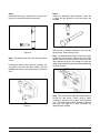
Slide the beater assembly the rest of the way into the
freezing cylinder.
Make sure the beater assembly is in position over the
drive shaft. Turn the beater slightly to be certain that
the beater is properly seated. When in position, the
beater will not protrude beyond the front of the
freezing cylinder.
Repeat Steps 1 and 2 for the other side of the freezers
on the Models 8756 and 8757.
Figure 3
Models 8752, 8756, 8757
21
Operating Procedures
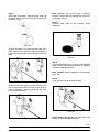
Insert the prime plug(s) into the hole(s) at the top of the
freezer door and push down.
Step 3
Assemble the freezer door. Place the large rubber
gasket(s) in the groove(s) on the back side of the
freezer door.
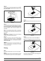
Slide the white plastic front bearing(s) over the baffle
rod(s), making certain that the flanged end of the
bearing is resting against the freezer door. DO NOT
lubricate the gasket(s) or front bearing(s).
Figure 8
Step 4
Install the freezer door. Insert the baffle rod(s) through
the beater(s) in the freezing cylinder(s). With the door
seated on the freezer studs, install the handscrews.
Tighten equally in a criss- cross pattern to insure the
door is snug.
Figure 6
Note: There are two gaskets and two front bearings
for the Models 8756 and 8757 door, one for each
freezing cylinder.
Slide the o- rings into the grooves on the prime plug(s).
Apply an even coat of lubricant to the o- rings and
shaft(s).
Note: On the Models 8756 and 8757, the short
handscrews go on the bottom and the long
handscrews go on the top.
Figure 7
Note: There are two prime plugs for the Models 8756
and 8757 door, one for each freezing cylinder.
Operating Procedures
Figure 9
22
Models 8752, 8756, 8757
Step 5
Install the draw valve(s). Slide the two o- rings into the
grooves on the draw valve(s) and lubricate.
Step 6
Install the adjustable draw handle(s). Slide the
o- ring(s) into the groove(s) on the pivot pin(s) and
lubricate.
Figure 12
Slide the fork of the draw handle(s) in the slot of the
draw valve(s). Secure with pivot pin.
Figure 10
Note: The Models 8756 and 8757 have three draw
handles and two pivot pins. Slide the fork of the draw
handle in the slot of the draw valve, starting from the
right. Slide the long pivot pin through the right and
middle draw handles. Secure the left draw handle with
the short pivot pin.
Note: The Models 8756 and 8757 have three draw
valves.
Lubricate the inside of the freezer door spout(s), top
and bottom, and insert the draw valve(s) from the
bottom until the slot in the draw valve(s) comes into
view.
Figure 13
Note: These units feature adjustable draw handles to
provide the best portion control, giving a better
consistency quality to your product, and controlling
costs. The draw handles can be adjusted for different
flow rates. See page 19 for more information on
adjusting these handles.
Figure 11
Models 8752, 8756, 8757
23
Operating Procedures
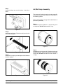
Air/Mix Pump Assembly
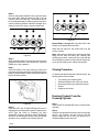
Step 7
Snap the design cap over the bottom of each door
spout.
The purpose of the air/mix pump is to meter a specific
amount of air and mix and transfer this combination to
the freezing cylinder.
Refer to the illustration on page 28 for identification of
parts during assembly.
Step 1
Assemble the piston. Slide the o- ring into the groove
on the piston. DO NOT lubricate this o- ring.
Figure 14
Step 8
Install the rear drip pan. Slide the rear drip pan into the
hole in the side panel.
Figure 17
Step 2
Assemble the liquid valve body. Slide the three check
bands and three o- rings into the grooves on the liquid
valve body. DO NOT lubricate the check bands or
o- rings.
Figure 15
Step 9
Install the front drip tray and the splash shield beneath
the door spout(s).
Figure 16
Operating Procedures
Figure 18
24
Models 8752, 8756, 8757
Note: Check bands have two smooth surfaces. A
concave shape indicates an incorrect assembly. Turn
the check band inside out to correctly expose the flat
surface.
Note: The drive hole in the piston must be visible
through the drive hole in the pump cylinder.
Figure 21
Step 4
Assemble the mix inlet fitting. Slide the o- ring into the
groove on the mix inlet fitting and lubricate with Taylor
Lube.
Figure 19
Step 3
Put a small amount of lubricant inside the piston and
insert the liquid valve body into the piston.
Apply a small amount of lubricant to the lower inside
diameter of the pump cylinder to a depth equivalent to
the length of your index finger. Once applied, the
amount of lubricant should be equal to a paper- thin
film.
Figure 22
Attach the spring and poppet to the end of the mix inlet
fitting above the o- ring. The spring must be securely
fastened and not allowed to float freely.
Note: The rubber poppet and spring act as a pressure
relief valve to prevent a pressure build- up in the
freezing cylinder.
Figure 20
Insert the assembled piston and liquid valve body into
the pump cylinder and push upwards. Align the steel
button at the base of the liquid valve body with the
cut- out groove at the bottom of the pump cylinder.
Models 8752, 8756, 8757
Figure 23
25
Operating Procedures
Insert the mix inlet fitting into the hole in the base of the
liquid valve body.
Step 5
Assemble the flare line and suction line. Assemble the
weighted end into the suction line. Attach the mix
suction line to the barbed end of the mix inlet fitting and
allow the weighted end to hang free. (Note: The
suction line must fit tightly against the mix inlet fitting.)
Figure 24
Figure 26
Secure the pump parts in position by sliding the
retaining pin through the cross holes located at the
bottom of the pump cylinder.
Push both nuts back from the flare end and lightly
lubricate the underside of the plastic flare. This will
allow the nut to turn freely without twisting the tubing.
Attach one end of the flare line to the threaded fitting
on the lower side of the pump cylinder and allow the
other end to hang free.
Figure 25
Operating Procedures
Figure 27
26
Models 8752, 8756, 8757
Note: Alignment of the air/mix pump is extremely
important. Severe and costly damage may occur if it is
not properly aligned.
Step 6
Secure the air/mix pump. Place the pump collar over
the pump cylinder. (The cross holes of the pump collar
should be on top.)
Step 7
Lubricate both sides
diaphragm.
of
the
pressure switch
Figure 28
Align the drive hole in the piston to the ball crank of the
motor reducer. At the same time, align the locating pin
hole in the pump cylinder to the locating pin on the face
plate.
Figure 31
Step 8
Place the diaphragm on the front face of the pressure
switch housing. The lubricant will act as an adhesive
to hold the diaphragm in place.
Note: DO NOT place the diaphragm in the pressure
switch cap.
Step 9
Screw the cap onto the housing securely.
Figure 29
Slide the pump collar upwards into the grooves on the
side of the face plate and secure the air/mix pump in
place by slipping the retaining pin through the cross
holes of the pump collar.
Figure 32
Repeat Steps 1 through 8 for the other side of the
freezer on the Models 8756 and 8757.
Figure 30
140306
Models 8752, 8756, 8757
27
Operating Procedures
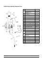
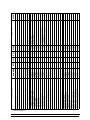
Air/Mix Pump Assembly Exploded View
Item
28
Part No.
Cap- Pump (Model 8752)
023324
1
Cap- Pump (Models
8756/8757)
021276- 9
2
Pin- Retaining
021276- 8
3
Pump Assembly
X36201
3a
Cylinder A.- Pump
022345- 1
3b
Pin- Retaining
021276- 8
3c
Piston
032733
3d
Ring- Check 2” OD x 1/2
020050
3e
O- Ring 2- 1/8 OD x .139 W
020051
3f
Body A.- Valve
X36202
3g
O- Ring - 13/16 OD x .139 W
021278
3h
Elbow- Inlet 90 Degree
022502- 4
3i
Spring- Tapered
022456
3j
Poppet- Rubber- Black
022473
3k
Ring- Check 1- 1/4 OD x 3/8
033215
3l
O- Ring - 1- 3/8 OD x .103 W
018664
4
Line A.- Flare
038299
Tube A.- Suction (8752)
X20450
Tube A.- Suction (8756- 8757)
X37293
Tube- Vinyl 5/8IDx1/8W (8752)
020945- 22
5a
Tube- Vinyl 5/8IDx1/8W
(8756- 8757)
020945- 18
5b
Counterweight- Suction Tube
020452
6
Line A.- Pump Pressure
X27139
6a
Socket- QD 3/16 Barb
020021
6b
Ferrule- 3/8 OD Brass
030553
6c
Tube- Vinyl 3/16 ID x 1/16 W
020940- 16
7
Diaphragm- Pressure Switch
020249
5
Operating Procedures
Description
Models 8752, 8756, 8757
Sanitizing
Step 4
Install the pressure line. Attach the quick disconnect
fitting of the pressure line to the other fitting on the mix
inlet tube just above the flare line and allow the other
end to hang free.
Step 1
Prepare a pail of approved 100 PPM sanitizing solution
(examples: 2- 1/2 gal. [9.5 liters] of Kay- 5R or 2 gal.
[7.6 liters] of Stera- SheenR). USE WARM WATER
AND FOLLOW THE MANUFACTURER’S SPECIFICATIONS. Place the pail of sanitizing solution inside the
mix cabinet.
Step 2
Brush clean the mix inlet tube with the long brush and
sanitizing solution.
Figure 35
Step 5
Insert the free end of the suction line and pressure line
into the pail of sanitizing solution.
Figure 33
Step 3
Connect the free end of the flare line to the threaded
fitting on the mix inlet tube.
Figure 36
Step 6
Place the power switch in the ON position.
Figure 34
080820
Models 8752, 8756, 8757
29
Operating Procedures
Step 9
Place an empty pail beneath the door spout and raise
the prime plug.
Step 7
Press the PUMP key. A light will come on, indicating
the air/mix pump is operating. This action will cause
the sanitizing solution to be pumped through the
air/mix pump and out through the pressure line. After
approximately 15 seconds, press the PUMP key. The
light will go out and the pump will stop operation.
Figure 39
Press the WASH and PUMP keys. The lights will come
on, indicating the pump and beater motor are
operating. When a steady stream of sanitizing
solution is flowing from the prime plug hole in the
bottom of the freezer door, press the PUMP key,
stopping pump operation. Push down the prime plug
and allow beater agitation for 5 minutes.
Figure 37
Step 8
Drain and connect the free end of the pressure line to
the pressure switch.
Figure 38
Operating Procedures
Figure 40
30
Models 8752, 8756, 8757
Step 10
After 5 minutes, open the prime plug. Press the PUMP
key. Pull the draw handle down and draw off the
remaining sanitizer.
Figure 42
Step 3
Place the free end of the suction line down in the mix
tank.
Figure 41
Step 11
Once the sanitizer stops flowing from the door spout,
close the draw valve. Press the PUMP and WASH
keys to stop operation. Disconnect the pressure line
from the pressure switch. Drain the sanitizer and
reconnect.
Note: On the Models 8756 and 8757, momentarily
pull down the center draw handle to sanitize the center
door spout.
Step 12
Repeat Steps 1 through 11 for the second freezing
cylinder on the Models 8756 and 8757.
Figure 43
Step 4
Install the funnel. Fill the mix tank with fresh mix.
Step 13
Prepare a sink with an approved sanitizing solution
(examples: Stera SheenR or Kay- 5R). USE WARM
WATER AND FOLLOW THE MANUFACTURER’S
SPECIFICATIONS.
Note: Use only fresh mix when priming the freezer.
Step 14
Take the following parts to the sink and sanitize: mix
tank(s), mix tank cover(s), mix probe(s), mix storage
cover(s) and funnel(s).
Priming
Step 1
Place the mix tank and the cover in the mix cabinet.
Figure 44
Step 2
Insert the prongs of the mix probe inside the mix tank
and connect the mix probe in the socket receptacle.
Remove the funnel and install the mix storage cover.
Close the mix cabinet door.
071017
Models 8752, 8756, 8757
31
Operating Procedures
Step 5
Place an empty pail beneath the door spout and open
the draw valve. With the prime plug still in the UP
position, press the PUMP key. This will allow the mix
to be pumped through the freezing cylinder and force
out any remaining sanitizer. When full strength mix is
flowing from the door spout, close the draw valve.
Figure 47
Repeat Steps 1 through 8 for the other side of the
freezer on the Models 8756 and 8757.
When the unit cycles off, the product will be at the
correct viscosity.
Note: Keep the mix cabinet door closed except when
filling the mix tank and during the cleaning and
sanitizing procedures. Leaving the door open with the
mix refrigeration system on may cause the evaporator
to ice up and impair the mix cabinet refrigeration.
Figure 45
Step 6
When a steady stream of mix is flowing from the prime
plug hole in the bottom of the freezer door, press the
PUMP key to stop operation.
Step 7
Once the stream of mix stops flowing from the prime
plug hole, push down the prime plug. Rinse the prime
plug hole area with water. Remove the pail and discard
the mix and the sanitizer.
Closing Procedure
To disassemble the Models 8752, 8756 and 8757, the
following items will be needed:
S
S
S
S
S
Two cleaning and sanitizing pails
Sanitized stainless steel rerun can with lid
Necessary brushes (provided with freezer)
Cleaner
Single service towels
Draining Product From the
Freezing Cylinder
Figure 46
Step 1
Press the AUTO and MIX REF keys to cancel freezer
operation.
Step 8
Press the AUTO key. The MIX REF light will come on
indicating the mix refrigeration system is operating, the
AUTO light will come on indicating the main
refrigeration system is operating, and the PUMP light
will come on indicating the air/mix pump will operate
whenever mix is needed in the freezing cylinder.
Step 2
Open the mix cabinet door and remove the mix storage
cover(s), mix probe(s), mix tank cover(s), and mix
tank(s). Empty the mix from the mix tank(s) into a
sanitized stainless steel rerun can.
140306
Operating Procedures
32
Models 8752, 8756, 8757
Step 3
Place the suction line in an empty pail in the mix
cabinet.
the prime plug hole in the bottom of the freezer door,
open the draw valve and drain all the rinse water.
Step 7
Once the rinse water stops flowing from the door
spout, close the draw valve and press the WASH and
PUMP keys to stop operation.
Step 4
If local health codes permit the use of rerun, place
a sanitized, NSF approved stainless steel rerun
container beneath the door spout. Open the draw
valve and press the WASH and PUMP keys. Drain all
the mix from the freezing cylinder. When all the product
stops flowing from the door spout, close the draw valve
and press the WASH and PUMP keys to stop
operation. Place the sanitized lid on the rerun
container and place it in the walk- in cooler.
Step 8
Disconnect the pressure line from the pressure switch.
Drain the water and then reconnect.
Step 9
Repeat this procedure using clean warm water, until
the water being discharged is clear.
Repeat Steps 1 through 9 for the second freezing
cylinder on the Models 8756 and 8757.
Note: If local health codes DO NOT permit the use
of rerun, the product must be discarded. Follow the
instructions in the previous step, except drain the
product into a pail and properly discard the mix.
Cleaning
Repeat Steps 3 through 4 for the second freezing
cylinder on the Models 8756 and 8757.
Step 1
Prepare a pail of approved 100 PPM cleaning solution
(examples: 2- 1/2 gal. [9.5 liters] of Kay- 5R or 2 gal.
[7.6 liters] of Stera- SheenR). USE WARM WATER
AND FOLLOW THE MANUFACTURER’S SPECIFICATIONS. Place the pail of cleaning solution inside the
mix cabinet and insert the suction line.
ALWAYS FOLLOW LOCAL HEALTH CODES.
Step 2
Disconnect the pressure line from the pressure switch
and place it in the pail of cleaning solution.
Rinsing
Step 1
Fill the empty pail in the mix cabinet with 2 gallons (7.6
liters) of cool, clean water. Place the free end of the
suction line in the pail of water.
Step 3
Press the PUMP key. This action will cause the
cleaning solution to be pumped through the air/mix
pump and out through the pressure line. After
approximately 15 seconds, press the PUMP key to
stop operation.
Step 2
Disconnect the pressure line from the pressure switch
and place it in the pail of water.
Step 4
Drain and connect the free end of the pressure line to
the pressure switch.
Step 3
Press the PUMP key. This action will cause the rinse
water to be pumped through the air/mix pump and out
through the pressure line. After approximately 15
seconds, press the PUMP key to stop operation.
Step 5
Place an empty pail beneath the door spout, raise the
prime plug, and press the WASH and PUMP keys.
Step 6
When a steady stream of solution is flowing from the
prime plug hole in the bottom of the freezer door, pull
down the draw handle and draw off the remaining
cleaning solution.
Step 4
Drain and connect the free end of the pressure line to
the pressure switch.
Step 5
Place an empty pail beneath the door spout. Raise the
prime plug and press the WASH and PUMP keys.
Step 7
Once the solution stops flowing from the door spout,
close the draw valve and press the WASH and PUMP
keys to stop operation.
Step 6
When a steady stream of rinse water is flowing from
140814
Models 8752, 8756, 8757
33
Operating Procedures
Repeat Steps 1 through 7 for the other side of the
freezer on the Models 8756 and 8757.
while too MILD of a solution will not provide adequate
cleaning. Make sure all brushes provided with the
freezer are available for brush cleaning.
Step 8
Place the power switch in the OFF position before
disassembling the machine.
Step 2
Remove the seal(s) from the drive shaft(s).
Step 3
Remove the scraper blade clips from the scraper
blades.
Disassembly
Step 4
From the freezer door(s) remove the gasket(s), front
bearing(s), pivot pin(s), draw handle(s), draw valve(s),
prime plug(s), and the design cap(s).
BE SURE THE POWER SWITCH IS IN THE
“OFF” POSITION TO ELIMINATE THE CHANCE OF
MOVING PARTS. CHECK TO MAKE SURE NO
LIGHTS ARE LIT ON THE CONTROL PANEL.
Remove all o- rings.
Note: To remove o- rings, use a single service towel
to grasp the o- ring. Apply pressure in an upward
direction until the o- ring pops out of its groove. With
the other hand, push the top of the o- ring forward. It
will roll out of the groove and can be easily removed.
If there is more than one o- ring to be removed, always
remove the rear o- ring first. This will allow the o- ring
to slide over the forward rings without falling into the
open grooves.
Step 1
Remove the handscrews, freezer door, beater(s),
shoes, scraper blades, and drive shaft(s) from the
freezing cylinder(s) and take them to the sink for
cleaning.
Step 2
Remove the air/mix pump. Unscrew the flare line from
the mix inlet tube. Disengage the pressure line from
the pressure switch and the mix inlet tube. Pull the
retaining pin out of the pump collar and slide the collar
down. Tilt the air/mix pump away from the machine
and take the entire assembly to the sink for further
disassembly and brush cleaning.
Step 5
Remove the flare line(s), suction line(s), retaining
pin(s) and mix inlet fitting(s) from the pump cylinder(s).
Remove the liquid valve body(ies) from the pump
cylinder(s).
Step 3
Remove the pressure switch cap from the mix cabinet
and the diaphragm from the cap.
Remove the piston(s) from the pump cylinder(s).
Remove all o- rings and check bands.
Step 6
Return to the freezer with a small amount of cleaning
solution. With the black bristle brush, brush clean the
rear shell bearing(s) at the back of the freezing
cylinder(s).
Repeat Steps 2 and 3 for the other side of the freezer
on the Models 8756 and 8757.
Step 4
Remove the front drip tray and splash shield.
Brush Cleaning
Step 1
Prepare a sink with an approved cleaning solution (examples: Stera SheenR or Kay- 5R). USE WARM WATER AND FOLLOW THE MANUFACTURER’S SPECIFICATIONS
If an approved cleaner other than Stera SheenR or
Kay- 5R
is used, dilute it according to the label
instructions. IMPORTANT: Follow the label directions.
Too STRONG of a solution can cause parts damage,
Figure 49
121218
Operating Procedures
34
Models 8752, 8756, 8757
located inside the machine, on the back of the
topping compartment.
Step 7
Using the long, flexible brush and the cleaning
solution, clean the mix inlet tube(s) located in the mix
cabinet. Thoroughly clean the tube(s) all the way up to
the freezing cylinder. This area needs special attention
because bacteria and milkstone can build up here.
Step 8
Remove the rear drip pan from the side panel and take
it to the sink for cleaning.
Note: If the rear drip pan is filled with an excessive
amount of mix, refer to the Troubleshooting Guide.
Step 9
Thoroughly brush clean all disassembled parts in the
cleaning solution, making sure all lubricant and mix film
is removed. Take particular care to brush clean the
draw valve core(s) in the freezer door. Place all the
cleaned parts on a clean dry surface to air dry
overnight.
Step 10
Wipe clean all exterior surfaces of the freezer and the
mix cabinet.
Check Topping Pump Temperature
and Volume - Model 8757
To check the topping pump temperature and volume
on the Model 8757 the following items will be needed:
S
S
S
S
Digital thermometer with needle probe
calibrating cup
flatblade screwdriver
sanitizer (examples: Stera SheenR
Kay- 5R)
Using the flatblade screwdriver, loosen and
remove the screws from the lower right panel.
Locate the adjustment screws, one for each
water bath.
5.
Using a flatblade screwdriver, turn the
adjustment screw CLOCKWISE to INCREASE
and COUNTERCLOCKWISE to DECREASE
the water bath temperature. Adjust in small
increments.
6.
Allow 10 minutes for the temperature to
stabilize in the water bath.
7.
Check the temperature again in the water bath.
8.
Place the topping pump back into the container.
9.
Repeat these steps for the other topping. Install
the lower right panel, if applicable, and install
the screws.
10.
Hold the small chamber of the calibrating cup
under the dispensing nozzle.
11.
Push the dispensing lever down for one full
stroke. The topping should be directed to the
bottom of the calibrating cup. Do not allow the
topping to fall on the sides of the cup.
or
Note: This procedure should be performed on a
morning after the pumps were disassembled and
cleaned, on a monthly basis.
1.
4.
Note: The amount of dispensed topping should be
one fluid ounce (29.6 ml).
Dispense one serving of topping into a sundae
cup.
12.
Note: Topping temperature should be between 115_
and 125_F (46_ and 52_C) and must be this
temperature before pump calibration can begin. Water
bath temperature should be between 135_ and 145_F
(57_ and 63_C).
If the dispensed amount is correct, proceed to
Step 13. If the amount of dispensed topping is
not correct, consult the Troubleshooting Section
of your Equipment Manual
13.
Repeat Steps 10 through 12 for the other
topping pump, then proceed with Step 14.
3.
14.
Topping pump temperature and volume check
is complete.
2.
Insert the sanitized needle probe into the
topping. Let the probe stabilize for 20 seconds.
If the temperature is too cold or too warm, it
can be adjusted by the temperature control
Models 8752, 8756, 8757
35
Operating Procedures
Section 7
Important: Operator Checklist
During Cleaning and Sanitizing
j 6. On a designated day of the week, run the mix as
low as feasible and discard after closing. This
will break the rerun cycle and reduce the
possibility of high bacteria and coliform counts.
ALWAYS FOLLOW LOCAL HEALTH CODES.
j 7. Properly prepare the cleaning and sanitizing
solutions. Read and follow the label directions
carefully. Too strong of a solution may damage
the parts and too weak of a solution will not do
an adequate job of cleaning or sanitizing.
Sanitize the freezing cylinder for 5 minutes.
Cleaning and sanitizing schedules are governed
by federal, state, or local regulatory agencies, and
must be followed accordingly. If the unit has a
“Standby mode”, it must not be used in lieu of
proper cleaning and sanitizing procedures and
frequencies set forth by the ruling health
authority. The following check points should be
stressed during the cleaning and sanitizing
operations.
j 8. The temperature of the mix in the mix storage
cabinet and the walk- in cooler should be below
40_F. (4.4_C.).
CLEANING AND SANITIZING MUST BE
PERFORMED DAILY.
Regular Maintenance Checks
Troubleshooting Bacterial Count
j 1. Replace scraper blades that are bent, damaged
or worn.
j 1. Thoroughly clean and sanitize the machine
regularly, including complete disassembly and
brush cleaning.
j 2. Before installing the beater, be certain that the
scraper blades are properly attached over the
pins and the beater assembly is straight.
j 2. Use all brushes supplied for thorough cleaning.
The brushes are specially designed to reach all
mix passageways.
j 3. Use the long (38”) white bristle brush to clean
the mix feed tube which extends from the mix
reservoir to the rear of the freezing cylinder.
j 3. Check the rear shell bearing for signs of wear
(excessive mix leakage in the rear drip pan) and
be certain it is properly cleaned.
j 4. Use the black bristle brush to thoroughly clean
the rear shell bearing located at the rear of the
freezing cylinder. Be sure there is a generous
amount of cleaning solution on the brush.
j 4. Using a screwdriver and cloth towel, keep the
rear shell bearing and the female hex drive
socket clean and free of lubricant and mix
deposits.
j 5. IF LOCAL HEALTH CODES PERMIT THE
USE OF RERUN, make sure the mix rerun is
stored in a sanitized, covered stainless steel
container and is used the following day. DO
NOT prime the machine with rerun. When using
rerun, skim off the foam and discard, then mix
the rerun with fresh mix in a ratio of 50/50 during
the day’s operation.
j 5. Dispose of o- rings and seals if they are worn,
torn, or fit too loosely, and replace with new
ones.
j 6. Follow all lubricating procedures as outlined in
“Assembly”.
080820
Important: Operator Checklist
36
Models 8752, 8756, 8757
The Air/Mix Pump
j 7. If your machine is air cooled, check the
condensers for accumulation of dirt and lint.
Dirty condensers will reduce the efficiency and
capacity of the machine. Condensers should be
cleaned monthly with a soft brush.
Note: For machines equipped with an air filter,
it will be necessary to vacuum clean the filters
on a monthly schedule.
j 1. Dispose of the o- rings, the check bands and
the pressure switch diaphragm if they are worn,
torn or fit too loosely and replace with new ones.
j 2. Follow lubricating procedures carefully. NEVER
lubricate check bands.
j 3. Handle plastic pump parts with care to avoid
nicks and cracks.
j 4. Be sure the pressure line is securely attached
to the pressure switch.
j 5. Clean, sanitize and lubricate the pressure
switch diaphragm daily.
Never use screwdrivers or other
metal probes to clean between the fins.
j 8. On water cooled units, check the water lines for
kinks or leaks. Kinks can occur when the
machine is moved back and forth for cleaning or
maintenance purposes. Deteriorated or
cracked water lines should be replaced only by
an authorized Taylor technician.
j 6. Be sure the air/mix pump is properly aligned
with the face plate of the motor reducer or
severe and costly damage may occur.
Winter Storage
j 9. Your machine is equipped with an auxiliary
refrigeration system. Check the auxiliary
condenser for accumulation of dirt and lint. Dirty
condensers will reduce the refrigeration
capacity of the mix cabinet. Condensers must
be cleaned monthly with a soft brush.
Note: For machines equipped with an air filter,
it will be necessary to vacuum clean the filters
on a monthly schedule.
If the place of business is to be closed during the winter
months, it is important to protect the freezer by
following certain precautions, particularly if the
building is subject to freezing conditions.
Disconnect the freezer from the main power source to
prevent possible electrical damage.
On water cooled freezers, disconnect the water
supply. Relieve pressure on the spring in the water
valve. Use air pressure on the outlet side to blow out
any water remaining in the condenser. This is
extremely important. Failure to follow this procedure
may cause severe and costly damage to the
refrigeration system.
Your local Taylor Distributor can perform this service
for you.
Wrap detachable parts of the freezer such as the
beater, blades, drive shaft, and freezer door. Place
these parts in a protected, dry place. Rubber trim parts
and gaskets can be protected by wrapping them with
moisture- proof paper. All parts should be thoroughly
cleaned of dried mix or lubrication which attract mice
and other vermin.
Never use screwdrivers or other
metal probes to clean between the fins.
080820
Models 8752, 8756, 8757
37
Important: Operator Checklist
Section 8
PROBLEM
1. No product is being
dispensed.
2. Insufficient mix in the
freezing cylinder.
Troubleshooting Guide
Troubleshooting Guide
PROBABLE CAUSE
REMEDY
PAGE
REF.
a. Low on mix. The MIX
OUT light is on.
a. Add mix to the mix tank
and press the AUTO key.
17
b. The power switch is in the
OFF position.
b. Place the power switch in
the ON position and press
the AUTO key.
- - -
c. The beater motor is out on
reset.
c. Reset the freezer.
d. The beater assembly is
rotating counterclockwise.
d. Contact service technician
to correct rotation to
clockwise.
- - -
e. Insufficient mix in the
freezing cylinder.
e. Refer to problem #2.
- - -
f. Restriction in the door
spout.
f. Remove the draw handle
and raise the draw valve
all the way up to remove
restriction. Never put
objects or fingers in door
spout.
- - -
g. Machine is unplugged.
g. Plug machine into the wall
receptacle.
- - -
h. Circuit breaker is off or the
fuse is blown.
h. Turn the breaker on or
replace the fuse.
- - -
i. The mix probe was not
installed properly, or was
damaged.
i. Check the mix probe
installation.
31
17
a. Suction line is not fully
submerged in the mix.
a. Arrange the suction line
so the weighted end is
fully submerged.
b. Improper seal of suction
line to the mix inlet fitting.
b. Remove the suction line
from the mix inlet fitting.
Place under hot running
water, allow tubing to
swell, then cool. Connect
suction line to barbed
fitting. Eventual
replacement will be
necessary.
- - -
c. Worn or defective check
bands or o- rings in air/mix
pump assembly.
c. Replace regularly. Never
lubricate check bands.
24/ 43
38
31
Models 8752, 8756, 8757
PROBLEM
PROBABLE CAUSE
REMEDY
PAGE
REF.
2. Insufficient mix in the
freezing cylinder. (Cont’d.)
d. Missing, defective, or no
lubrication on the mix inlet
fitting o- ring.
d. Replace or evenly
lubricate the o- ring on the
mix inlet fitting.
25/ 43
e. The mix pump ball crank
is broken.
e. Contact a service
technician to replace the
ball crank.
- - -
f. The pump motor is not
activated.
f. Place the power switch in
the OFF position. Push
the reset button on pump
drive motor. Return the
power switch to the ON
position. Press the AUTO
key. (For the Models 8756
and 8757, press the
AUTO key for the opposite
freezing cylinder also.)
- - -
g. Defective air/mix pump
pressure switch.
g. Contact a service
technician to replace the
pressure switch.
- - -
h. Pressure switch
diaphragm installed
incorrectly, or missing.
h. Diaphragm must be
correctly installed in the
pressure switch cap or the
housing.
27
i. The mix inlet tube is
frozen or clogged.
i. Use the long flexible brush
and sanitizing solution to
clear the restriction in the
mix inlet tube. Contact a
service technician to
correct the cause of
over- refrigeration in the
mix cabinet.
- - -
j. The mix pump is pumping
foam.
j. Incorrect handling of
rerun. Must remove all
foam.
3. Product is too stiff.
Models 8752, 8756, 8757
36
a. Viscosity control is set too
cold.
a. Contact a service
technician.
- - -
b. Insufficient mix in the
freezing cylinder.
b. Refer to problem #2.
- - -
c. Improper priming
procedures.
c. Drain the freezing cylinder
and reprime the machine.
31
d. Out- of- date mix.
d. Use fresh mix. When
using rerun, skim off the
foam and mix 50% rerun
with 50% fresh mix during
heavy draw periods.
31/ 43
39
Troubleshooting Guide
PROBLEM
4. Product is too soft.
PROBABLE CAUSE
REMEDY
PAGE
REF.
a. Viscosity control is set too
warm.
a. Contact a service
technician.
b. Worn scraper blades.
b. Replace scraper blades
regularly.
43
c. Dirty condensers or air
filters on air cooled units.
c. Clean monthly.
37
d. Inadequate water supply
on water cooled units.
d. Check the water supply.
Check water lines for
leaks or kinks.
e. Draw rate is set too fast.
e. Adjust the draw rate to 5
to 7- 1/2 ounces of
product every 10 seconds.
Check that the restrictive
bar on the draw handle is
assembled on the bottom.
19
f. Inadequate air space
around air cooled units.
f. Allow adequate room for
air flow across the
condensers. Minimum of
3” (7.6 cm) clearance on
all sides. Do not obstruct
air discharge on top. 12”
(30.5 cm) clearance on
top of freezer.
1
a. Warm mix was placed in
the tank.
a. Mix added to the mix tank
should be below 40_F
(4.4_C).
36
b. The mix cabinet door was
left open.
b. The door must be kept
closed.
31
c. The mix cabinet
refrigeration system needs
adjustment.
c. Contact a service
technician.
- - -
d. The mix cabinet door
gasket is not sealing.
d. Repair or replace gasket.
- - -
e. Dirty mix cabinet
condenser or air filter.
e. Clean monthly.
6. Mix in the mix cabinet is
too cold.
a. The mix cabinet
refrigeration system needs
adjustment.
a. Contact a service
technician.
7. Excessive mix leakage
from the bottom of the
door spout.
b. Worn, missing or incorrect
o- ring is on the draw
valve.
b. Check the o- rings.
(Replace every 3 months.)
43
c. Improper lubrication on
the draw valve o- rings.
c. Lubricate properly.
23
5. Mix in the mix cabinet is
too warm.
Troubleshooting Guide
40
- - -
1/ 37
37
- - -
Models 8752, 8756, 8757
PROBLEM
8. Excessive mix leakage
into the rear drip pan.
9. The drive shaft is stuck in
the gear box coupling.
10. Freezing cylinder walls are
scored.
Models 8752, 8756, 8757
PROBABLE CAUSE
REMEDY
PAGE
REF.
a. Worn or missing drive
shaft seal.
a. Install or replace the seal.
20/ 43
b. Improper lubrication of the
drive shaft.
b. Lubricate properly.
c. Worn rear shell bearing.
c. Contact a service
technician to replace the
rear shell bearing.
- - -
d. The gear box is out of
alignment.
d. Contact a service
technician to align the
gear box.
- - -
a. The gear box is out of
alignment.
a. Contact a service
technician to align the
gear box.
- - -
b. Rounded corners on hex
end of drive shaft or gear
coupling.
b. Replace damaged
component.
- - -
a. Broken pins on beater
assembly.
a. Repair or replace the
beater assembly. Be sure
the scraper blades are
properly seated on pins.
21
b. The beater assembly is
bent.
b. Repair or replace the
beater assembly. Contact
a service technician to
correct the cause of
insufficient mix in freezing
cylinder.
- - -
c. Missing front bearing.
c. Install the front bearing on
the back of the freezer
door.
22
41
20
Troubleshooting Guide
PROBLEM
11. The air/mix pump does
not operate.
12. The machine will not
operate in the AUTO
mode.
Troubleshooting Guide
PROBABLE CAUSE
REMEDY
PAGE
REF.
a. The pump motor is not
activated.
a. Place the power switch in
the OFF position. Push
the reset button on the
pump drive motor. Return
the power switch to the
ON position. (Models
8756 and 8757, press the
AUTO key for the opposite
freezing cylinder also.)
- - -
b. Defective air/mix pump
pressure switch.
b. Contact a service
technician to replace the
pressure switch.
- - -
c. The pressure switch
diaphragm was installed
incorrectly or was missing.
c. The diaphragm must be
correctly installed in the
pressure switch cap or the
housing.
27
a. The machine is
unplugged.
a. Plug the machine into the
wall receptacle.
- - -
b. The circuit breaker is off
or the fuse is blown.
b. Turn the breaker on or
replace the fuse.
- - -
c. Low on mix. The MIX
OUT light is flashing.
c. Add mix to the mix tank
and press the AUTO key.
17
d. The mix probe is not
installed properly or is
damaged.
d. Check the mix probe
installation.
31
e. The beater motor is out on
reset.
e. Reset the freezer.
17
f. The unit is off on high
head pressure.
f. Air cooled: clean the
condenser.
Water cooled: check the
water supply.
Contact a service
technician.
37/ 37
g. The power switch is in the
OFF position.
g. Place the power switch in
the ON position.
29
42
Models 8752, 8756, 8757
Section 9
PART DESCRIPTION
Parts Replacement Schedule
EVERY 3
MONTHS
EVERY 4
MONTHS
Scraper Blades
EVERY 6
MONTHS
ANNUALLY
X
QTY.
2*
Drive Shaft Seal
X
1*
Freezer Door Gasket
X
1*
Front Bearing
X
1*
Beater Shoes
X
2*
Draw Valve O- Ring
X
2**
Prime Plug O- Ring
X
2*
Pivot Pin O- Ring
X
1*
Air/Mix Pump O- Ring
X
4*
Liquid Valve Body Check Band
X
3*
Mix Inlet Fitting O- Ring
X
1*
Pressure Switch Diaphragm
X
1*
Design Cap
X
1**
White Bristle Brush, 9/16” x 44”
Inspect &
Replace if
Necessary
Minimum
1
White Bristle Brush, 1” x 2”
Inspect &
Replace if
Necessary
Minimum
1
White Bristle Brush, 3” x 7”
Inspect &
Replace if
Necessary
Minimum
1
White Bristle Brush, 3” x 1/2”
Inspect & Replace if Necessary
Minimum
1
Small White Bristle Brush
Inspect & Replace if Necessary
Minimum
1
Double Ended Brush
Inspect &
Replace if
Necessary
Minimum
1
Black Bristle Brush, 1” x 2”
Inspect &
Replace if
Necessary
Minimum
1
* Double quantity for Models 8756 and 8757.
** Triple quantity for Models 8756 and 8757.
Refer to Parts List on page 49 when ordering the above parts.
Models 8752, 8756, 8757
43
Parts Replacement Schedule
Section 10 Limited Warranty on Equipment
TAYLOR COMPANY LIMITED WARRANTY ON FREEZERS
Taylor Company, a division of Carrier Commercial Refrigeration, Inc. (“Taylor”) is pleased to provide this limited
warranty on new Taylor-branded freezer equipment available from Taylor to the market generally (the “Product”)
to the original purchaser only.
LIMITED WARRANTY
Taylor warrants the Product against failure due to defect in materials or workmanship under normal use and
service as follows. All warranty periods begin on the date of original Product installation. If a part fails due to
defect during the applicable warranty period, Taylor, through an authorized Taylor distributor or service agency,
will provide a new or re- manufactured part, at Taylor’s option, to replace the failed defective part at no charge for
the part. Except as otherwise stated herein, these are Taylor’s exclusive obligations under this limited warranty for
a Product failure. This limited warranty is subject to all provisions, conditions, limitations and exclusions listed
below and on the reverse (if any) of this document.
Product
Soft Serve
Frozen Yogurt
Shakes
Smoothies
Frozen Beverage
Batch Desserts
Part
Limited Warranty Period
Insulated shell assembly
Five (5) years
Refrigeration compressor
(except service valve)
Five (5) years
Beater motors
Two (2) years
Beater drive gear
Two (2) years
Printed circuit boards and
Softech controls beginning
with serial number H8024200
Two (2) years
Parts not otherwise listed in
this table or excluded below
One (1) year
LIMITED WARRANTY CONDITIONS
1.
If the date of original installation of the Product cannot be verified, then the limited warranty period begins
ninety (90) days from the date of Product manufacture (as indicated by the Product serial number). Proof of
purchase may be required at time of service.
2.
This limited warranty is valid only if the Product is installed and all required service work on the Product is
performed by an authorized Taylor distributor or service agency, and only if genuine, new Taylor parts are
used.
3.
Installation, use, care, and maintenance must be normal and in accordance with all instructions contained in
the Taylor Operator’s Manual.
4.
Defective parts must be returned to the authorized Taylor distributor or service agency for credit.
5.
The use of any refrigerant other than that specified on the Product’s data label will void this limited warranty.
LIMITED WARRANTY EXCEPTIONS
This limited warranty does not cover:
1.
Labor or other costs incurred for diagnosing, repairing, removing, installing, shipping, servicing or handling of
defective parts, replacement parts, or new Products.
2.
Normal maintenance, cleaning and lubrication as outlined in the Taylor Operator’s Manual, including cleaning
of condensers.
131210
Limited Warranty on Equipment
44
Models 8752, 8756, 8757
3.
Replacement of wear items designated as Class “000” parts in the Taylor Operator’s Manual.
4.
External hoses, electrical power supplies, and machine grounding.
5.
Parts not supplied or designated by Taylor, or damages resulting from their use.
6.
Return trips or waiting time required because a service technician is prevented from beginning warranty
service work promptly upon arrival.
7.
Failure, damage or repairs due to faulty installation, misapplication, abuse, no or improper servicing,
unauthorized alteration or improper operation or use as indicated in the Taylor Operator’s Manual, including
but not limited to the failure to use proper assembly and cleaning techniques, tools, or approved cleaning
supplies.
8.
Failure, damage or repairs due to theft, vandalism, wind, rain, flood, high water, water, lightning, earthquake
or any other natural disaster, fire, corrosive environments, insect or rodent infestation, or other casualty,
accident or condition beyond the reasonable control of Taylor; operation above or below the electrical or
water supply specification of the Product; or components repaired or altered in any way so as, in the
judgment of the Manufacturer, to adversely affect performance, or normal wear or deterioration.
9.
Any Product purchased over the Internet.
10.
Failure to start due to voltage conditions, blown fuses, open circuit breakers, or damages due to the
inadequacy or interruption of electrical service.
11.
Electricity or fuel costs, or increases in electricity or fuel costs from any reason whatsoever.
12.
Damages resulting from the use of any refrigerant other than that specified on the Product’s data label will
void this limited warranty.
13.
Any cost to replace, refill or dispose of refrigerant, including the cost of refrigerant.
14.
ANY SPECIAL, INDIRECT OR CONSEQUENTIAL PROPERTY OR COMMERCIAL DAMAGE OF ANY
NATURE WHATSOEVER. Some jurisdictions do not allow the exclusion of incidental or consequential
damages, so this limitation may not apply to you.
This limited warranty gives you specific legal rights, and you may also have other rights which vary from
jurisdiction to jurisdiction.
LIMITATION OF WARRANTY
THIS LIMITED WARRANTY IS EXCLUSIVE AND IS IN LIEU OF ALL OTHER WARRANTIES, CONDITIONS
AND/OR REMEDIES UNDER THE LAW, INCLUDING ANY IMPLIED WARRANTIES OR CONDITIONS OF
MERCHANTABILITY OR FITNESS FOR A PARTICULAR PURPOSE. THE ORIGINAL OWNER’S SOLE
REMEDY WITH RESPECT TO ANY PRODUCTS SHALL BE REPAIR OR REPLACEMENT OF DEFECTIVE
COMPONENTS UNDER THE TERMS OF THIS LIMITED WARRANTY. ALL RIGHTS TO CONSEQUENTIAL
OR INCIDENTAL DAMAGES (INCLUDING CLAIMS FOR LOST SALES, LOST PROFITS, PRODUCT LOSS,
PROPERTY DAMAGES OR SERVICE EXPENSES) ARE EXPRESSLY EXCLUDED. THE EXPRESS
WARRANTIES MADE IN THIS LIMITED WARRANTY MAY NOT BE ALTERED, ENLARGED, OR CHANGED
BY ANY DISTRIBUTOR, DEALER, OR OTHER PERSON, WHATSOEVER.
LEGAL REMEDIES
The owner must notify Taylor in writing, by certified or registered letter to the following address, of any defect or
complaint with the Product, stating the defect or complaint and a specific request for repair, replacement, or other
correction of the Product under warranty, mailed at least thirty (30) days before pursuing any legal rights or
remedies.
Taylor Company
a division of Carrier Commercial Refrigeration, Inc.
750 N. Blackhawk Blvd.
Rockton, IL 61072, U.S.A.
Models 8752, 8756, 8757
45
Limited Warranty on Equipment
Section 11
Limited Warranty on Parts
TAYLOR COMPANY LIMITED WARRANTY ON TAYLOR GENUINE PARTS
Taylor Company, a division of Carrier Commercial Refrigeration, Inc. (“Taylor”) is pleased to provide this limited
warranty on new Taylor genuine replacement components and parts available from Taylor to the market generally
(the “Parts”) to the original purchaser only.
LIMITED WARRANTY
Taylor warrants the Parts against failure due to defect in materials or workmanship under normal use and service
as follows. All warranty periods begin on the date of original installation of the Part in the Taylor unit. If a Part fails
due to defect during the applicable warranty period, Taylor, through an authorized Taylor distributor or service
agency, will provide a new or re- manufactured Part, at Taylor’s option, to replace the failed defective Part at no
charge for the Part. Except as otherwise stated herein, these are Taylor’s exclusive obligations under this limited
warranty for a Part failure. This limited warranty is subject to all provisions, conditions, limitations and exclusions
listed below and on the reverse (if any) of this document.
Limited Warranty Period
Part’s Warranty Class Code or Part
Class 103 Parts¹
Three (3) months
Class 212 Parts²
Twelve (12) months
Class 512 Parts
Twelve (12) months
Class 000 Parts
No warranty
Taylor Part #072454 (Motor- 24VDC *C832/C842*)
Four (4) years
LIMITED WARRANTY CONDITIONS
1.
If the date of original installation of the Part cannot be otherwise verified, proof of purchase may be required
at time of service.
2.
This limited warranty is valid only if the Part is installed and all required service work in connection with the
Part is performed by an authorized Taylor distributor or service agency.
3.
The limited warranty applies only to Parts remaining in use by their original owner at their original installation
location in the unit of original installation.
4.
Installation, use, care, and maintenance must be normal and in accordance with all instructions contained in
the Taylor Operator’s Manual.
5.
Defective Parts must be returned to the authorized Taylor distributor or service agency for credit.
6.
This warranty is not intended to shorten the length of any warranty coverage provided pursuant to a separate
Taylor Limited Warranty on freezer or grill equipment.
7.
The use of any refrigerant other than that specified for the unit in which the Part is installed will void this
limited warranty.
1, 2
Except that Taylor Part #032129SER2 (Compressor-Air-230V SERV) and Taylor Part #075506SER1
(Compressor-Air-115V 60HZ) shall have a limited warranty period of twelve (12) months when used in Taylor
freezer equipment and a limited warranty period of two (2) years when used in Taylor grill equipment.
131210
Limited Warranty on Parts
46
Models 8752, 8756, 8757
LIMITED WARRANTY EXCEPTIONS
This limited warranty does not cover:
1.
Labor or other costs incurred for diagnosing, repairing, removing, installing, shipping, servicing or handling of
defective Parts, replacement Parts, or new Parts.
2.
Normal maintenance, cleaning and lubrication as outlined in the Taylor Operator’s Manual, including cleaning
of condensers or carbon and grease buildup.
3.
Required service, whether cleaning or general repairs, to return the cooking surface assemblies, including
the upper platen and lower plate, to an operational condition to achieve proper cooking or allow proper
assembly of release sheets and clips as a result of grease build-up on the cooking surfaces, including but
not limited to the platen and plate, sides of the shroud or top of the shroud.
4.
Replacement of cooking surfaces, including the upper platen and lower plate, due to pitting or corrosion (or
in the case of the upper platen, due to loss of plating) as a result of damage due to the impact of spatulas or
other small wares used during the cooking process or as a result of the use of cleaners, cleaning materials
or cleaning processes not approved for use by Taylor.
5.
Replacement of wear items designated as Class “000” Parts in the Taylor Operator’s Manual, as well as any
release sheets and clips for the Product’s upper platen assembly.
6.
External hoses, electrical power supplies, and machine grounding.
7.
Parts not supplied or designated by Taylor, or damages resulting from their use.
8.
Return trips or waiting time required because a service technician is prevented from beginning warranty
service work promptly upon arrival.
9.
Failure, damage or repairs due to faulty installation, misapplication, abuse, no or improper servicing,
unauthorized alteration or improper operation or use as indicated in the Taylor Operator’s Manual, including
but not limited to the failure to use proper assembly and cleaning techniques, tools, or approved cleaning
supplies.
10.
Failure, damage or repairs due to theft, vandalism, wind, rain, flood, high water, water, lightning, earthquake
or any other natural disaster, fire, corrosive environments, insect or rodent infestation, or other casualty,
accident or condition beyond the reasonable control of Taylor; operation above or below the gas, electrical or
water supply specification of the unit in which a part is installed; or Parts or the units in which they are
installed repaired or altered in any way so as, in the judgment of Taylor, to adversely affect performance, or
normal wear or deterioration.
11.
Any Part purchased over the Internet.
12.
Failure to start due to voltage conditions, blown fuses, open circuit breakers, or damages due to the
inadequacy or interruption of electrical service.
13.
Electricity, gas or other fuel costs, or increases in electricity or fuel costs from any reason whatsoever.
14.
Damages resulting from the use of any refrigerant other than that specified for the unit in which the Part is
installed will void this limited warranty.
15.
Any cost to replace, refill or dispose of refrigerant, including the cost of refrigerant.
16.
ANY SPECIAL, INDIRECT OR CONSEQUENTIAL PROPERTY OR COMMERCIAL DAMAGE OF ANY
NATURE WHATSOEVER. Some jurisdictions do not allow the exclusion of incidental or consequential
damages, so this limitation may not apply to you.
This limited warranty gives you specific legal rights, and you may also have other rights which vary from
jurisdiction to jurisdiction.
Models 8752, 8756, 8757
47
Limited Warranty on Parts
LIMITATION OF WARRANTY
THIS LIMITED WARRANTY IS EXCLUSIVE AND IS IN LIEU OF ALL OTHER WARRANTIES, CONDITIONS
AND/OR REMEDIES UNDER THE LAW, INCLUDING ANY IMPLIED WARRANTIES OR CONDITIONS OF
MERCHANTABILITY OR FITNESS FOR A PARTICULAR PURPOSE. THE ORIGINAL OWNER’S SOLE
REMEDY WITH RESPECT TO ANY PRODUCTS SHALL BE REPAIR OR REPLACEMENT OF DEFECTIVE
PARTS UNDER THE TERMS OF THIS LIMITED WARRANTY. ALL RIGHTS TO CONSEQUENTIAL OR
INCIDENTAL DAMAGES (INCLUDING CLAIMS FOR LOST SALES, LOST PROFITS, PRODUCT LOSS,
PROPERTY DAMAGES OR SERVICE EXPENSES) ARE EXPRESSLY EXCLUDED. THE EXPRESS
WARRANTIES MADE IN THIS LIMITED WARRANTY MAY NOT BE ALTERED, ENLARGED, OR CHANGED
BY ANY DISTRIBUTOR, DEALER, OR OTHER PERSON, WHATSOEVER.
LEGAL REMEDIES
The owner must notify Taylor in writing, by certified or registered letter to the following address, of any defect or
complaint with the Part, stating the defect or complaint and a specific request for repair, replacement, or other
correction of the Part under warranty, mailed at least thirty (30) days before pursuing any legal rights or remedies.
Taylor Company
a division of Carrier Commercial Refrigeration, Inc.
750 N. Blackhawk Blvd.
Rockton, IL 61072, U.S.A.
Limited Warranty on Parts
48
Models 8752, 8756, 8757
024259
X20305
031324
028992
028991
012864
X46231
046235
046236
050348
022848
022849
023877
039422
039433
X30153-27
030157-27
X47833-27
031314
033047
X30160
046536-27
X36641SER1
X32326-SER
033745
013072
013073
021101
023316
BELT-AX35
BELT-AX36
BELT-AX42
BLOCK-TERMINAL 2P
BLOCK-TERMINAL 3P
BLOWER A. (NEW)
MOTOR-BLOWER FAN
BLOWER A.
BOOT-CAPACITOR INSULATING
CAPACITOR-RUN- 10 UF/370V
HOUSING A.-W/WHEEL
MOTOR-BLOWER-208/230V 50/60 HZ
BOARD-LOGIC-GEN 2
BOARD-POWER-GEN 1 & 2
BRACKET-THERM PROBE
BRUSH-DOUBLE ENDED
BRUSH-DRAW VALVE 1”ODX2”X17”L
BRUSH-FEED TUBE 9/16ODX44 DA
BRUSH-MIX PUMP BODY-3”X7”WHITE
PART
NUMBER
ADAPTOR-PUMP-CABINET
BEARING A.-HINGE
BEARING-REAR SHELL *NICK.PLATE
+GUIDE-DRIP SEAL
+NUT-BRASS BEARING
+WASHER-BEARING LOCK
BEATER A.-3.4QT-1 PIN-SUPPORT
+BLADE-SCRAPER-PLASTIC 8-1/8L
+CLIP-SCRAPER BLADE
BEARING-FRONT-SHOE
DESCRIPTION
Models 8752, 8756, & 8757
49
1
1
1
1
1
1
1
2
2
2
1
1
1
1
1
1
1
1
2
2
8752
QTY.
4
4
1
1
1
1
1
1
1
2
2
1
1
1
1
1
4
2
1
2
2
2
2
2
4
4
2
8756
QTY.
1
1
1
1
1
2
2
1
1
1
1
1
4
4
4
2
1
2
2
2
2
2
4
4
2
8757
QTY.
000
000
000
103
103
103
103
103
000
103
103
103
212
212
103
000
000
000
000
103
000
000
000
000
000
103
000
103
000
WARR.
CLASS
MIX CABINET
8756-PRIOR TO J9025975
1 PHASE
3 PHASE
J9025975/UP
50Hz/60Hz
USE W/BEATER SHOES - ORDER
X50350 KIT
REMARKS
139
139
PARTS
UPDATE
MAIN REFIGERATION SYSTEM HP- 62, 8752 - J6090915/UP, 8756 - J5032993/UP, 8757 - J5111000/UP
Section 12
Parts List
+ Available Separately
Parts List
111129
+ Available Separately
Parts List
50
Models 8752, 8756, & 8757
027647
013071
033059
X21989
X24799
032444
014218
023324
021276-9
021276-8
021279
030307
019481
001086
037442
029841048627-
050106-27
052397029439
031304
052401-27
048259012906
031790
038145
050104
048629
029797
012721
042511
+RELAY-START-COMPRESSOR (404A)
COMPRESSOR CS18K6E- COPELAND
+CAPACITOR-RUN 35UF/370V
+CAPACITOR-START 215-259UF/250V
*RELAY-START-COMPRESSOR
COMPRESSOR L63A113BBCA - BRISTOL
+CAPACITOR-RUN- 20UF/440V
+CAPACITOR-START-161-193UF/25
*RELAY-START-COMPRESSOR
CONDENSER-AC-18LX14H-4ROW (NEW)
CONDENSER-AC-18LX14H-3ROW
CONDENSER-AC-9X8 -2 ROW
COUPLING-DRIVE 3/4 HEX X 1-7/8
+SCREW-5/16-18 X 5/16 ALLEN SET
PART
NUMBER
BRUSH-PRESSURE SWITCH-1/8”DIA
BRUSH-REAR BRG 1IN.DX2IN.LGX14
BRUSH-1/2 INCH DIA.
CABINET A.-INSULATED *8752
CABINET A.-INSULATED *8756
CABLE-RIBBON-PWR/RELAY-18 IN
CAP-DESIGN-1.010”ID-6 POINT
CAP-PUMP
CAP-PUMP
+PIN-RETAINING
CASTER-SWV-3” SWV 3/4-10 STEM
CASTER-SWV-3” SWV 3/4-10 STEM W/BRAKE
COLLAR-HOLDING
+SCREW-10-32 X 3/4 OVAL HD SS
+WASHER-HOLDING COLLAR
COMPRESSOR AEA3414APP-AE121EL (R12)
COMPRESSOR AEA0415ZXD-AE580ET (404A)
DESCRIPTION
1
1
1
2
1
1
1
1
1
1
1
2
2
2
1
1
1
1
1
1
8752
QTY.
1
1
1
1
1
2
2
2
2
1
2
1
2
4
2
1
2
4
2
2
2
2
1
2
2
2
2
12
12
6
1
1
2
2
2
2
1
1
1
2
3
1
1
1
8757
QTY.
1
2
3
2
1
8756
QTY.
103
512
103
103
103
512
103
103
103
103
103
103
103
000
000
000
000
103
103
103
000
103
103
103
103
103
103
000
000
512
512
WARR.
CLASS
MIX CABINET - 230-60-1
MAIN - 8756 - J9025975/UP
230-60-1
230-60-1
230-60-1
MAIN - 8756 - PRIOR TO J9025975
230-60-1
230-60-1
230-60-1
J9025975/UP
MAIN - 8756 - PRIOR TO J9025975
MIX CABINET
MIX CABINET - PRIOR TO 404A
MIX CABINET - 8752-J6090915/UP,
60Hz-8757-J6012711/UP,
8756-J5120589/UP
PUMP COLLAR
PUMP COLLAR
REMARKS
139
139
139
139
139
139
139
PARTS
UPDATE
+ Available Separately
Models 8752, 8756, & 8757
51
Parts List
DECAL-TROUBLESHOOTING
DIAGRAM-WIRING *8752*GEN.
DIAGRAM-WIRING *8756*GEN.II*
DIAGRAM-WIRING *8757*GEN II*
DOOR A.-1 SPOUT
+BEARING-FRONT
+GASKET-DOOR HT 4”-DOUBLE
+HANDLE A.-DRAW-ADJ.
+HANDLE-ADJUSTABLE
+O-RING-1/4 OD X .070W 50 DURO
+SCREW-ADJUSTMENT-PLASTIC
+O-RING-3/8 OD X .070W
+O-RING-5/16 OD X .070W
+O-RING-7/8 OD X .103W
+PIN A.-PIVOT
+PLUG-PRIME
+VALVE A.-DRAW
COVER-COMPRESSOR-SOUND BARRIER
COVER A.-MIX TANK
COVER-MIX STORAGE-CENTER
+BOOT-MIX COVER
COVER-MIX TANK
COVER-LEFT MIX STORAGE
+BOOT-MIX COVER
COVER-RIGHT MIX STORAGE
+BOOT-MIX COVER
DECAL-CLEAN INST.-CABINET
DECAL-DEC-SGL-SS-CABINET
DECAL-DEC-TWIN-SS-CABINET
DECAL-DEC-TAYLOR 8757
DECAL-POWER SWITCH
DESCRIPTION
038374
037808
037807
042793X51531-10
023262
048926
X26996
028804
015872
026592
016137
016272
014402
X22820
028805
X18303
052816
X38726
038827
037200
024590
037138
037200
037139
037200
024735
033227
032424
036700
032484
PART
NUMBER
1
1
1
1
1
1
1
2
1
2
1
1
1
1
1
1
1
1
1
1
1
8752
QTY.
1
1
1
1
1
1
1
1
1
1
1
8756
QTY.
1
1
1
1
1
1
1
1
1
1
8757
QTY.
000
000
000
000
103
000
000
103
103
000
000
000
000
000
103
103
103
103
103
103
000
103
103
000
103
000
000
000
000
000
000
WARR.
CLASS
PRIME PLUG
PIVOT ROD
DRAW VALVE
(8757 - PRIOR TO J8120000) NEW
8757 POWER SWITCH LABEL 052632
J9025975/UP
REMARKS
137
139
PARTS
UPDATE
+ Available Separately
Parts List
52
Models 8752, 8756, & 8757
DOOR A.-3 SPOUT
+GASKET-DOOR-4” SHELL
+HANDLE A.-DRAW-ADJ.
+HANDLE-ADJUSTABLE
+O-RING-1/4 OD X .070W 50 DURO
+SCREW-ADJUSTMENT-STAINLESS
+NUT-5/16-24 18-8 SS JAM
+O-RING-3/8 OD X .070W
+O-RING-5/16 OD X .070W
+O-RING-7/8 OD X .103W
+PLUG-PRIME
+ROD A.-PIVOT
+ROD A.-PIVOT
+SEAL-DRAW VALVE
+VALVE A.-DRAW
+VALVE A.-DRAW
DOOR A.-INS. *5460-1-454DOOR A.-INS.MIX-8657/8756
DOOR A.-INS.MIX-TEMP CTR.
DRYER-CAP. TUBE-HP62 {DUAL}
DRYER-FILTER-HP62-3/8 X 1
EVAPORATOR-12L X 4H X 1-7/8T
FAN-EVAPORATOR 2900RPM-18W/60H
FUNNEL-MIX
FUSE-15 AMP CARTRIDGE
GASKET-MIX DOOR
GASKET-CAB MIX DOOR
GEAR A.*REDUCER
GUARD-FAN
GUIDE A.-DRIP PAN *8752*
GUIDE A.-DRIP PAN *8756*
HINGE-SELF CLOSING DOOR
PIN A.-UPPER HINGE
DESCRIPTION
X51532-12
048926
X33687
028804
015872
033662
029639-BLK
016137
016272
014402
028805
X22388
X22387
034698
X18303
X45380
X22178
X24816
X24816-SP1
049346
048901
X30939
028534036637
027582
020134
024629
021286
028534-1
X28603
X28628
020143
X20315
PART
NUMBER
1
1
1
2
1
1
1
1
2
1
2
1
1
8752
QTY.
1
1
2
1
1
2
4
1
2
2
1
1
1
1
2
2
1
1
1
1
2
3
3
3
3
3
4
1
6
2
1
1
1
3
1
8757
QTY.
1
2
1
1
2
4
1
1
2
3
3
3
3
3
4
1
6
2
1
1
1
3
1
8756
QTY.
103
000
103
103
000
000
000
000
000
000
103
103
103
000
103
103
103
103
103
000
000
103
103
103
000
000
000
212
103
103
103
103
103
WARR.
CLASS
MIX CABINET
MIX CABINET
104
118
118
118
J5080000 THRU J7060000
J7060000 (3)
J5080000 THRU J7060000
MIX CABINET
118
PARTS
UPDATE
PRIME PLUG
PIVOT ROD
DRAW VALVE
REMARKS
+ Available Separately
Models 8752, 8756, & 8757
53
Parts List
PLATE-LOWER HINGE
HOLDER-FUSE 300 VOLT PANEL MT.
HOOD
HOOD
INDICATOR-DIGITAL-TEMP SOLAR
INDICATOR-DIGITAL-TEMP SOLAR
JAR-SYRUP-PLASTIC
JAR-SYRUP-STAINLESS
+LID W/LADLE 1OZ
KIT A.-TUNE UP-1 SPOUT-NO
BEARING-FRONT
CAP-DESIGN-1.010”ID-6 POINT
O-RING-7/8 OD X .103W
O-RING-3/8 OD X .070W
O-RING-5/16 OD X .070W
O-RING-1-3/8 OD X .103W-#123
RING-CHECK 2 IN OD X 1/2
O-RING-2-1/8 OD X .139W-#225
DIAPHRAGM-PRESSURE SWITCH
O-RING-13/16 OD X .139W
SEAL-DRIVE SHAFT
RING-CHECK 1-1/4 OD X 3/8
TOOL- 0-RING REMOVAL
GASKET-DOOR HT 4”-DOUBLE
KIT A.-TUNE UP-3 SPOUT-NON HT
BEARING-FRONT-SHOE
CAP-DESIGN-1.010”ID-6 POINT
DIAPHRAGM-PRESSURE SWITCH
GASKET-DOOR HT 4”-DOUBLE
O-RING-1-3/8 OD X .103W
O-RING-13/16 OD X .139W
O-RING-2-1/8 OD X .139W
O-RING-3/8 OD X .070W
DESCRIPTION
020323
027581
050464
048526
051234
039236
036573
036574
036575
X49463-15
050348
014218
014402
016137
016272
018664
020050
020051
020249
021278
032560
033215
048260-WHT
048926
X49463-2
050348
014218
020249
048926
018664
021278
020051
016137
PART
NUMBER
1
1
1
2
2
1
1
2
3
1
1
1
1
1
1
1
2
1
8752
QTY.
1
2
3
2
2
2
2
6
4
1
1
1
2
2
2
1
1
2
3
2
2
2
2
6
4
1
4
8757
QTY.
1
4
8756
QTY.
103
103
103
103
103
103
103
103
103
000
000
000
000
000
000
000
000
000
000
000
000
000
000
000
000
000
000
000
000
000
000
000
000
WARR.
CLASS
USE W/BEATER SHOES X50350 KIT
J9050000/UP
PRIOR TO J9050000
REMARKS
PARTS
UPDATE
140814
+ Available Separately
Parts List
54
Models 8752, 8756, & 8757
O-RING-5/16 OD X .070W
O-RING-7/8 OD X .103W
RING-CHECK 1-1/4 OD X 3/8
RING-CHECK 2 IN OD X 1/2
SEAL-DRAW VALVE
SEAL-DRIVE SHAFT
SHOE-FRONT HELIX *FRONT*
SHOE-FRONT HELIX *REAR*
TOOL- 0-RING REMOVAL
LABEL-DOOR-WARN-MOVE PART
LABEL-WARN-COVER
LABEL-SWITCH-HEATER
LABEL-SWITCH-HEATER
LABEL-SWITCH-POWER OFF/ON
LINE A.-FLARE
LINE A.-PUMP PRESSURE
FERRULE-3/8 OD BRASS
SOCKET-QD. 3/16 BARB
TUBE-VINYL 3/16ID X 1/16 WALL
LUBRICANT-TAYLOR 4 OZ.
MAN-OPER 8752/8756/8757
MOTOR-FAN 9 WATT 1550RPM*FAN-5 BLADE 7 ” PUSH 30D
MOTOR-FAN 120 W 208/230V 60H
*CAPACITOR-RUN- 4UF-370V
*FAN-5 BLADE 12”PUSH 32DEG
MOTOR-1.5 HP
MOTOR-REDUCER 54 RPM-SS
NUT-STUD *GENERAL USAGE*
NUT-STUD *460-664-754-56*LONG
NUT-STUD *460-664-754-56*SHORT
PAIL-10 QT.
PAN A.-DRIP *8752*
DESCRIPTION
016272
014402
033215
020050
034698
032560
050347
050346
048260-WHT
032749
051433
036551
052183-SYM
052632
038299
X27139
030553
020021
020940-16
047518
028752-M
012768016289
041401019624
047279
021522030913021508
034382
034383
013163
X23008
PART
NUMBER
2
1
1
1
2
2
1
1
1
1
1
1
1
1
1
1
4
1
5
8752
QTY.
2
2
2
2
2
2
2
2
1
6
2
4
1
2
2
2
1
1
7
1
1
1
2
2
4
4
2
1
1
8757
QTY.
2
2
2
2
4
4
2
1
1
1
6
2
4
1
2
2
2
1
1
6
8756
QTY.
000
000
000
000
000
000
000
000
000
000
000
000
000
000
103
103
000
103
000
000
000
103
103
103
103
103
212
103
103
103
103
000
103
WARR.
CLASS
EXPANSION VALVE
HANDSCREWS
HANDSCREWS
HANDSCREWS
MAIN SYSTEM
MIX CABINET
PRIOR TO J8120000
J8120000/UP
J8120000/UP
J5080000 THRU J7060000
REMARKS
137
137
137
118
PARTS
UPDATE
+ Available Separately
Models 8752, 8756, & 8757
55
Parts List
PAN A.-DRIP *8756*
PAN A.-DRIP *8757*
PAN-DRIP 11-5/8 LONG
PAN-DRIP 17-1/4”LONG
PAN-DRIP 17-1/4” LONG
PANEL A.-FRONT *8752*
PANEL A.-FRONT *8756*
PANEL A.-FRONT *8757*
PANEL A.-LOWER SIDE
PANEL A.-LOWER SIDE
PANEL-LOWER REAR *5454-87
PANEL-LOWER REAR *657-756*
PANEL-LOWER REAR *8757*
PANEL-UPPER REAR *454-8-7
PANEL-UPPER REAR *657-756*
PANEL-UPPER REAR *8757*
PANEL-UPPER SIDE LEFT
PANEL-UPPER SIDE RIGHT
PIN-PIVOT
PLATE-DEC-8752
PLATE A.-DEC-8756
PLATE A.-DEC-8757
PLUG-DRIP TRAY HOLE
PROBE A.-MIX-W/BALL CONNECTORS
PROBE A.-THERMISTOR
PROBE A.-THERMISTOR *SHORT*
* BRACKET-THERMISTOR PROBE
PULLEY-2AK22 X .625-.6265
PULLEY-2AK74-5/8
PUMP A.-COAX *SS*A*
BODY A.-COAX VALVE *SS*A*
CYLINDER A.-PUMP
ELBOW-INLET 90 DEG.
DESCRIPTION
X22811
X36761
027503
027504
036232
X22997
X22879
X36711
X23956
X36741
025128
023598
042067
022074
022015
042068
028599
028600
013592
033347
X32138
X32138
029595
X35981
X31602
X36267
033745
016403
027822
X36201
X36202
022345-1
022502-4
PART
NUMBER
1
1
1
1
1
1
1
1
1
1
1
1
1
1
1
1
2
1
1
8752
QTY.
1
2
2
1
1
2
2
2
2
2
2
1
1
1
2
1
1
2
1
1
1
8756
QTY.
1
1
2
2
1
1
2
2
2
2
2
2
1
1
1
2
1
2
1
1
1
8757
QTY.
103
103
103
103
103
103
103
103
103
103
103
103
103
103
103
103
103
103
103
103
103
103
000
103
103
103
103
103
103
103
103
103
103
WARR.
CLASS
MIX CABINET
BARREL
MIX CABINET
MIX CABINET
BEATER MOTOR
GEAR
HINGED
HINGED
FOR RESET
RIGHT & LEFT
RIGHT & LEFT
8” NOTCH AT REAR
EXPANSION VALVE
EXPANSION VALVE
REMARKS
PARTS
UPDATE
071018
+ Available Separately
Parts List
56
Models 8752, 8756, & 8757
O-RING-1-3/8 OD X .103W
O-RING-13/16 OD X .139W
O-RING-2-1/8 OD X .139W
PIN-RETAINING
PISTON-COAX PUMP *A* WHITE
POPPET-RUBBER-BLACK
RING-CHECK 1-1/4 OD X 3/8
RING-CHECK 2 IN OD X 1/2
SPRING-TAPERED 1-7/8L
PUMP A.-SYRUP-TAN
RELAY-3 POLE-20A-208/240 50/60
RELAY-SPDT-30 A-240 V
RELAY-OVRLD
SANITIZER KAY-5 (125 PACKETS)
SANITIZER-STERA SHEET-GREEN
SHAFT-BEATER
+SEAL-DRIVE SHAFT
SHELL A.-INSULATED *8752*
+STUD-NOSE CONE
SHELL A.-INSULATED *8756*
+STUD-NOSE CONE
SHIELD-SPLASH *5454-8-752
SHIELD-SPLASH 23 L
SHROUD A.-EVAPORATOR
SHROUD A.-EVAPORATOR
SOCKET A.-PROBE*BALL&SOCK*60IN
CLIP-BALL CONNECTOR
SCREW-5-40 X 1/4 SOCKET CAP SS
STARTER
STRIP-TOP TRIM
SWITCH-PRESSURE 440 PSI-S
SWITCH-TOGGLE-4PDT*ON-NONE-ON
SWITCH-TOGGLE-DPDT*ON-NONE-ON
DESCRIPTION
018664
021278
020051
021276-8
032733
022473
033215
020050
022456
036623
012725032607049651041082
065293
032564
032560
X24369
022822
X24347
022822
022765
022766
X49124
X21983
X36615
035813
037843
041950024827
048230
024295
037394
PART
NUMBER
1
1
1
3
3
1
1
1
1
1
4
1
2
6
6
2
1
2
1
1
1
4
1
4
1
1
1
2
6
6
2
1
2
2
2
1
2
2
6
2
2
2
2
4
2
2
2
1
8757
QTY.
1
2
2
2
1
2
1
1
2
2
6
2
2
2
2
4
2
8756
QTY.
1
1
3
1
1
1
1
2
1
8752
QTY.
000
000
000
103
103
000
000
000
103
103
103
103
103
000
000
103
000
512
103
512
103
103
103
103
103
103
000
000
103
103
103
103
103
WARR.
CLASS
MIX CABINET ( 8756-J5120589/UP)
MIX CABINET (J5032993-J5120588)
REMARKS
104
104
PARTS
UPDATE
+ Available Separately
Models 8752, 8756, & 8757
57
Parts List
SWITCH-TOGGLE-SPST
SWITCH-TOGGLE-SPST
SWITCH A.-DRAW
ARM A.-DRAW *750-1-2*MC*
BRACKET A.-SWITCH *750-1-2*M
E-RING 3/16 .335 O.D.
PIN-PIVOT
SPRING-RETURN R.
SWITCH-LEVER-SPDT-10A-125-25
SWITCH A.-DRAW *TWIN TWIST
ARM-SWITCH-DRAW-LEFT
ARM-SWITCH-DRAW-RIGHT
BRACKET A.-SWITCH *338-39-754
E-RING 1/4
PIN-PIVOT-DRAW SWITCH
SPRING-RETURN L.
SPRING-RETURN R.
SWITCH A.-DRAW-TWIN TWIST
BRACKET-DRAW SWITCH-TWIN TWIST
SWITCH-LEVER-SPDT-11A-125-277V
SWITCH A.-PRESSURE*DELRIN CAP*
BODY-PRESSURE SWITCH*DELRIN*
CAP-PRESSURE SWITCH
DIAPHRAGM-PRESSURE SWITCH
O-RING-1/2ID X 5/8 OD
PISTON-PRESSURE SWITCH*DELRIN
SPRING-COMP.480X.047X1.00
SWITCH-PLUNGER-SPDT15A125-250V
TANK-MIX-15 GALLON-PLASTIC
TANK A.-MIX W/DECALS
DECAL-MIX TANK-RIGHT SIDE OUT
DECAL-MIX TANK-WRONG SIDE OUT
TANK-MIX 9-GALLON TAPERED BTM
DESCRIPTION
012626
015974
X33322
X33326
X33323
049178
015478
023488
028889
X38921
038649
038650
X38252
032190
038484
023487
023488
X39269
039264
039252
X32660
032633
032635
020249
017998
032634
032651
032260
020275
X38755
038751
038750
034928
PART
NUMBER
1
1
1
1
1
1
1
1
1
1
1
1
1
1
1
1
8752
QTY.
1
1
1
1
2
1
1
1
1
1
2
2
2
2
2
2
2
2
2
2
2
2
2
2
2
2
2
1
1
8757
QTY.
1
1
1
1
2
1
1
1
1
1
2
2
2
2
2
2
2
2
2
8756
QTY.
103
103
103
103
103
000
103
103
103
103
103
103
103
000
103
103
103
103
103
103
103
103
000
000
000
103
103
103
103
103
000
000
103
WARR.
CLASS
MIX CABINET
PRIOR TO J8120000
J8120000/UP
REMARKS
137
137
PARTS
UPDATE
+ Available Separately
Parts List
58
Models 8752, 8756, & 8757
X23124
X36735
019330
032886
X20450
020452
020945-22
X37293
020452
020945-18
020941-30
020941-36
029406
044404
044455
TUBE-VINYL 1/4ID X 1/16WALL
VALVE-ACCESS 1/4 X 3/8 SOLDER
VALVE-ACCESS 1/4FL X 1/4SOLDER
VALVE-ACCESS 1/4FL X 3/8S
035793
020157
014533
X20426
X24813
X36732
X22423
X22424
024974
024826
022071
022013
036740
024824-SP
024825
024976
PART
NUMBER
TOOL-LIQ.VALVE BODY EXTRACTING
TRAY-DRIP 16-7/8L X 5-1/8
TRAY-DRIP 22-7/8L X 5-1/8W
TRIM A.-SHELF *5454-8752*
TRIM A.-SHELF *657-756*
TRIM A.-SHELF *8757*
TRIM A.-UPPER SIDE *5454TRIM A.-SIDE *657-756*
TRIM-BOTTOM MIX DOOR
TRIM-BOTTOM MIX DOOR
TRIM-REAR CORNER *5454-87
TRIM-REAR CORNER *657-756*
TRIM-REAR CORNER *8757*
TRIM-FRONT LEFT
TRIM-FRONT RIGHT
TRIM-TOP MIX DOOR
TRIM-TOP MIX DOOR
TUBE A.-MIX INLET
TUBE A.-MIX INLET
+O-RING-13/16 OD X .103W
+SEAL-INLET TUBE
TUBE A.-SUCTION *22 INCH*
COUNTERWEIGHT-SUCTION TUBE
TUBE-VINYL 5/8 ID X 1/8 WALL
TUBE A.-SUCTION *18 INCH*
COUNTERWEIGHT-SUCTION TUBE
TUBE-VINYL 5/8 ID X 1/8 WALL
TUBE-VINYL 1/4ID X 1/16WALL
DESCRIPTION
1
1
1
1
1
1
1
1
1
1
1
1
1
2
1
2
1
1
1
8752
QTY.
1
1
1
2
2
2
1
2
2
1
2
1
1
2
1
2
1
1
1
2
2
2
1
2
2
1
1
2
1
1
1
2
1
1
1
1
1
8757
QTY.
1
8756
QTY.
000
103
103
103
103
103
000
000
103
103
000
103
103
000
000
000
103
103
103
103
103
103
103
103
103
103
103
103
103
103
103
WARR.
CLASS
BULK P/N R30312
AXV DRAIN
BULK P/N R30326
BULK P/N R30312 MIX CAB
SHROUD
BULK P/N R30326
SEE STRIP-TOP TRIM (024827)
BELOW DRIP TRAY
BELOW DRIP TRAY
BELOW DRIP TRAY
REMARKS
PARTS
UPDATE
+ Available Separately
Models 8752, 8756, & 8757
59
Parts List
BELT-AX36
BELT-AX43
BLOCK-TERMINAL 2P
BLOCK-TERMINAL 2P
BLOCK-TERMINAL 3P
BLOCK-TERMINAL 4P
COMPRESSOR - CS18K6E - COPELAND
+ CAPACITOR-RUN- 45UF/370V
+ CAPACITOR-START-145-175UF/250V
+ RELAY-START-COMPRESSOR
50Hz
BRACKET-FAN
BRACKET-FAN
CONDENSER-WC-COAX
ENCLOSURE-FAN *8657-8756*
FAN-5 BLADE 7 ” PUSH 30D
HOSE-RUBBER 1/2”ID X 7/8”
MOTOR-FAN 9 WATT 1450RPMOUTLET A.-TEE
SHROUD A.-CONDENSER *8657
VALVE-WATER 3/8 REG/HEAD
SWITCH-PRESSURE 350 PSI-SOLDER
WATER COOLED
VALVE-ACCESS 1/4FL X 3/8SOLDER
VALVE-ACCESS-1/4 MFLX1/4 S-90
VALVE-EPR 1/4S
VALVE-EXP-AUTO-1/4S X1/4 FPT
+BOOT-EXPANSION VALVE
VIDEO-TRAIN FILM-SS-CABINET
WIRE A.-PRESSURE*LONG*
* BOOT-PRESSURE SWITCH
DESCRIPTION
022849
022865
039421
039422
039423
039424
052397052400
052399
052401-27
022077
048524
048287
X31852
016289
R50200
012768X25900
X30957
046686
048231
043232
047016
022665
046365
050900
038417-V
X32663
032624
PART
NUMBER
2
2
2
2
1
1
1
10ft
1
1
1
1
1
1
1
1
1
1
8752
QTY.
4
4
4
2
2
2
2
1
2
1
2
17ft
2
1
1
2
2
2
2
1
2
2
1
2
2
8756
QTY.
4
4
4
4
1
2
1
2
25ft
2
1
1
2
2
2
2
1
2
2
1
2
2
8757
QTY.
000
000
103
103
103
103
512
103
103
103
103
103
103
103
103
000
103
103
103
103
103
103
103
103
103
000
000
103
000
WARR.
CLASS
SINGLE PHASE
SINGLE PHASE
THREE PHASE
THREE PHASE
MAIN
MAIN - SINGLE PHASE
MAIN - SINGLE PHASE
MAIN - SINGLE PHASE
FOR X32660 PRESSURE SWITCH
MIX CABINET
REMARKS
104
PARTS
UPDATE
+ Available Separately
Parts List
60
Models 8752, 8756, & 8757
048259-40
023739
031790
038146
048627-40
051234-C
050107-40
011545
038417-PAL
INDICATOR-DIGITAL TEMP-SOLAR (CELSIUS)
RELAY-START-COMPRESSOR
PULLEY-2AK27 x .625-.6265
VIDEO-TRAIN FILM-SS-CABINET
PART
NUMBER
COMPRESSOR L63A113BBKA - BRISTOL
+ CAPACITOR-RUN- 25UF/370V
+ CAPACITOR-START-161-193UF/250V
+ RELAY-START-COMPRESSOR
COMPRESSOR AEA0415ZXC-AE580JT TECUMSEH
DESCRIPTION
1
1
1
1
1
1
1
1
8752
QTY.
1
2
1
2
2
2
2
1
8756
QTY.
1
1
2
1
2
2
2
2
1
8757
QTY.
103
103
103
000
512
103
103
103
512
WARR.
CLASS
J9050000/UP
MIX CABINET - SINGLE PHASE
BEATER MOTOR
MAIN
MAIN - SINGLE PHASE
MAIN - SINGLE PHASE
MAIN - SINGLE PHASE
MIX CABINET
REMARKS
PARTS
UPDATE
6
8
7
BRN
7
3-BTR 5
4-BTR 10
5-FAN 2
6-STBY DIS
7-INTERVAL
1-COMP 5
2-COMP 10
WHT
BRN
RED
BRN
MIX
OUT
BLK
TIME
16
14
11
5
MIN
S.S.VISCOSITY
SWITCH INTERVAL
TAYLOR CO.
MIX
DRAW
MAX
MIN
MIX
SET POINT
STANDBY
MAX
SHK
PUMP
MIN
DIP SWITCH
UP = OFF
42002
AUTO
WASH
MIX OUT
MIX LOW
MIX 1
WHT
B
B
BLK
(SEE FIG. 4)
M1
BLK
YEL
STBY TEMP.
(SEE NOTE 1)
BRL
PROBE
BLK
BLK
BLK
TEMP.
MIX HOPPER
HIGH PRESS.
CUTOUT
STANDBY
MAX
B
BLK
96
95
8-INTERVAL
SHAKE TEMP.
MFG DATE
FAN MIX 2
BLK
BLK/WHT
BLK/WHT
BLK/WHT
13
GRN/YEL
L1 FUSE
2PDT
L3
L2
POWER
T3
L1
LK
B
SWITCH
BTR
T2
T1
PUMP
A2
L3
L2
L1
FAN
BLK/WHT
T1
BLK
14
OVERLOAD RESET
T2
CONTACTOR
A1
13
BLK
BLK
BLK
BLK
BLK
L3
L2
L1
BLK
BLK
BLK
BLK
LINE
LINE
L2
M
BLK
BLK
M
A1
COMP
GND
BLK/WHT
BEATER MOTOR
OVERLOAD SWITCH
B
(SEE FIG. 4)
POWER/RELAY BOARD
BTR
GRN/YEL
BLK
M
CONTACTOR
T2
T1
BLK
GRN/YEL
L1
8
24VAC
2
MIX
LOW
OFF
ON
OFF
ON
BLK
BLK/WHT
PRESSURE
SW.
BLK
4
3
M
OL
NO
BLK
3
OFF
OFF
ON
ON
4
OVLD.
RESET
MIX
PUMP
RED
BLK
BLU
PUMP ROTATION
AS VIEWED
FROM FRONT
BRN
(SEE FIG. 3)
M
BLK
WHT
BLK
BLU
M
SEE FIG.2
T3
BLK
BLU
14
SEE FIG.1
COMP
BRN
BLK
L2 FUSE
2
1
4
2
B
B
C0M
WIRE #11 OF
RIBBON CABLE
BLK
L2
L3
L1
BEATER MOTOR
OVERLOAD
T1
T2
LINE
LINE
WHT
NO
MOTOR
CCW
OVLD.
RELAY
2 4
3
BLK
WHT
ALTERNATE WIRING
DIAGRAM
PRP
BLK
WHT
LINE
MIX PUMP
FIG. 3
MAGNETEK BEATER MOTOR WIRING
2
5
3
1
6
4
BLACK
BLUE
BLUE
BLACK
T2
S
2
1
1
2
3
4
RELAY
BLUE
BLACK
BLUE
BLACK
COMPRESSOR
TERMINAL
COVER
START CAP.
L1
L2
L1
BEATER MOTOR
OVERLOAD
L3
BEATER MOTOR
CONTACTOR
T1
L2
BEATER MOTOR
CONTACTOR
T3
T2
RUN
CAP.
36880-2
RUN CAPACITOR
BROWN
BROWN
L3
BEATER MOTOR
CONTACTOR
T3
BEATER MOTOR
CONTACTOR
T1
BEATER MOTOR
OVERLOAD
STEPS:
1) REMOVE BROWN JUMPER FROM BETWEEN TERMINAL #1 TO TERMINAL #5
2) MOVE BLUE INTERNAL (FROM MOTOR MAIN WINDING)
FROM TERMINAL #5 TO TERMINAL #1.
NOTE: FOR CCWLE - BLUE INTERNAL ON #1, YELLOW INTERNAL ON #6
BLUE INTERNAL
ORANGE INTERNAL
RED INTERNAL
LEESON BEATER MOTOR WIRING
YELLOW INTERNAL
R
STEPS:
1) DISCONNECT WIRE T7 FROM TERMINAL 3
2) SPLICE BLUE WIRE AS SHOWN
BLACK INTERNAL
T1
T8
T7
T4
T5
C
5
4
WHITE
2
RELAY
1
C
INTERNAL OVERLOAD
5
4
R
BLEED RESISTOR
BLACK
S
ABOVE ELECTRICAL DIAGRAM SHOWS WIRING NECESSARY
TO HOOK UP A COMPRESSOR USING A STAR T AND RUN
CAPACITOR (CSR) WITH A RELAY.
EQUIPMENT
GROUND
BLUE
BRISTOL COMPRESSOR
SCHEMATIC WIRING DIAGRAM - CSR
START CAPACITOR
FIG. 1
BEATER MOTOR
CONTACTOR
T3
BEATER MOTOR
CONTACTOR
BLUE
BLACK
BLUE
RUN
CAP.
BLACK
BROWN
BROWN
R
FIG. 2
DOOR INTERLOCK
SWITCH
FIG. 4
GE/RBC BEATER MOTOR WIRING
5
RELAY
COMPRESSOR
TERMINAL
COVER
A
NOTE: FOR CCWLE - BLUE INTERNAL ON #1,YELLOW INTERNAL ON #2
T1 OR BLUE INTERNAL
T8 OR RED INTERNAL
J12 OR PURPLE INTERNAL
J9 OR BLACK INTERNAL
S
T4 OR YELLOW INTERNAL
C
2
R
5
1
START CAP.
4
1
C
INTERNAL OVERLOAD
5
BLACK
S
ABOVE ELECTRICAL DIAGRAM SHOWS WIRING NECESSARY
TO HOOK UP A COMPRESSOR USING A START AND RUN
CAPACITOR (CSR) WITH A RELAY.
4
RELAY
WHITE(120 VOLTS; 220V-50Hz)
BLACK(230 VOLTS)
WHITE
BLACK
EQUIPMENT
GROUND
BLUE
052396-1
RUN CAPACITOR
BLEED RESISTOR
COPELAND COMPRESSOR
SCHEMATIC WIRING DIAGRAM - CSR
START CAPACITOR
L1
L2 DR N
Taylor Company
Model 8752
037808
04/14
c 2014 Carrier Commercial Refrigeration, Inc.
NC
C
2
BLK
1
4
2
3
PTC RELAY
MIX COMP.
WHT
L2
L1
DRAW
SWITCH
WHT
R
MIX COMPRESSOR
C
S
OVERLOAD
(MOTOR PROTECTOR)
WHT
MIX COND. FAN
WHT
PUMP
SOFTECH CONTROL
YEL
RED/BLK
ORN
MIX
BLK
BLK
MIX EVAP FANS
WHT
WHT
WHT
WHT
ORN
BEATER
CP
GRN/YEL
BLK
BTR.
RED/BLK
A2
FAN - (A/C & W/C)
CAPACITOR
USED ON
AIR COOLED
ONLY
WHT
COMP.
BLK
BLK
BLK
1) STANDBY TEMP. PROBE IS NOT PRESENT ON
MODELS WITHOUT THE STANDBY MODE FEATURE
NOTES:
YEL
WHT
WHT
WHT
NO
BRN
7
MIN
1-COMP 5
2-COMP 10
BRN
RED
MIX
LOW
MIX
OUT
BRN
MIX
DRAW
BLK
MIN
S.S.VISCOSITY
STANDBY
SET POINT
MAX
SHK
PUMP
MIN
MIX
DIP SWITCH
UP = OFF
42002
AUTO
WASH
MIX OUT
MIX LOW
MIX 1
WHT
B
B
(SEE FIG. 2)
BLK
I1
BLK
YEL
STBY TEMP.
(SEE NOTE 1)
STANDBY
BRL
PROBE
BLK
BLK
BLK
BLK
TEMP.
MIX HOPPER
HIGH PRESS.
CUTOUT
96
B
95
BLK/WHT
BEATER MOTOR
OVERLOAD SWITCH
(SEE FIG. 2)
B
BLK
BLK/WHT
BLK/WHT
BLK/WHT
BLK
GRN/YEL
L1 FUSE
2PDT
SWITCH
POWER
POWER/RELAY BOARD
GND
BLK
MAX
SHAKE TEMP.
MFG DATE
SOFTECH CONTROL
OVERLOAD RESET
A2
A1
14
13
T3
L3
T2
L2
T1
L1
BLK
BLK
8-INTERVAL
COMP
BLK
BTR
L3
BLK
L2
BLK
L1
BLK
BLK
BLK
BLK
BLK
L3
PUMP
FAN
BLK/WHT
T3
BLK
T2
BTR.
RELAY
T1
A1
13
BLK
L3
BLK
L2
BLK
L1
BLK
M
L2
WHT
3-BTR 5
4-BTR 10
5-FAN 2
6-STBY DIS
7-INTERVAL
2
3
M
TAYLOR CO.
MAX
24VAC
4
BLK
BTR
BLK
M
BLK
M
BEATER
T3
BLK
T2
BLK
COMP.
RELAY
T1
BLK
BLK
BLK
WHT
RED/BLK
A2
14
FAN - (A/C & W/C)
BRN
WHT
COMP
CAPACITOR
USED ON
AIR COOLED
ONLY
BLK
BLK
L1
8
BLK
SWITCH INTERVAL
BLK
BLK/WHT
PRESSURE
SW.
BLK
TIME
16
14
11
5
C
NC
DRAW
SWITCH
8
7
OFF
ON
OFF
ON
NO
L2 DR N
L1
6
MIX
PUMP
RED
BLU
OVLD.
RESET
(SEE FIG. 1)
PUMP ROTATION
AS VIEWED
FROM FRONT
BRN
GRN/YEL
M
L2 FUSE
Taylor Company
Model 8752
037808-33
04/14
c 2014 Carrier Commercial Refrigeration, Inc.
OFF
OFF
ON
ON
C0M
WIRE #11 OF
RIBBON CABLE
BLK
BLK
WHT
4
3
BLK
1
2
M
OL
B
B
RELAY
2 4
3
ALTERNATE WIRING
DIAGRAM
PRP
BLK
WHT
LINE
DOOR INTERLOCK
SWITCH
FIG. 2
MOTOR
CCW
2
R
3
4
PTC RELAY
MIX COMP.
WHT
L2
L1
OVLD.
MIX PUMP
FIG. 1
WHT
C
S
WHT
MIX COND. FAN
WHT
PUMP
YEL
NOTES:
1) STANDBY TEMP. PROBE IS NOT PRESENT ON
MODELS WITHOUT THE STANDBY MODE FEATURE
OVERLOAD
(MOTOR PROTECTOR)
YEL
WHT
WHT
FAN MIX 2
RED/BLK
ORN
MIX
BLK
BLK
MIX EVAP FANS
WHT
WHT
WHT
WHT
ORN
BLK
BLK
GRN/YEL
BLK
WHT
L2 DR N
NC
NO
7
BRN
3-BTR 5
4-BTR 10
5-FAN 2
6-STBY DIS
7-INTERVAL
WHT
TAYLOR CO.
MIX
MIX
OUT
DRAW
MIN
S.S.VISCOSITY
SET POINT
STANDBY
MAX
SHK
PUMP
MIN
MIX
DIP SWITCH
UP = OFF
42002
AUTO
WASH
MIX OUT
MIX LOW
MIX 1
MAX
SHAKE TEMP.
STANDBY
SOFTECH CONTROL
BRL
PROBE
BRN
RED
BRN
BLK
WHT
B
(SEE FIG. 2)
B
H1
BLK
BLK
YEL
STBY TEMP.
(SEE NOTE 1)
BLK
BLK
BLK
BLK
96
95
BLK/WHT
GND
BLK
8-INTERVAL
BLK/WHT
BLK/WHT
BLK
L1 FUSE
GRN/YEL
OVERLOAD RESET
2PDT
SWITCH
POWER
A2
14
13
T3
L3
T2
L2
T1
L1
BTR
L3
BLK
L2
BLK
L1
PUMP
BLK
BLK
BLK
BLK
BLK
BLK
BLK
BLK
L3
GRN/YEL
FAN
BLK/WHT
T3
T2
BLK
BLK
BLK
T1
A1
13
L3
BLK
L2
L1
COMP.
RELAY
BLK
BLk
BLK
T1
M
A1
COMP
BLK
M
EXT.
GRD.
B
BEATER MOTOR
OVERLOAD SWITCH
(SEE FIG. 2)
TEMP.
MIX HOPPER
HIGH PRESS.
CUTOUT
B
POWER/RELAY BOARD
BTR
BLK/WHT
3
2
M
MIX
LOW
24VAC
4
BLK
BRN
GRN/YEL
BLK
BTR.
RELAY
BLK
T2
BLK
BLK
M
L2
8
MAX
BLK
OVLD.
RESET
MIX
PUMP
RED
BLU
(SEE FIG. 1)
PUMP ROTATION
AS VIEWED
FROM FRONT
M
BEATER
T3
BLK
COMP
WHT
MIX EVAP FANS
BRN
CAPACITOR
USED ON
AIR COOLED
ONLY
GRN/YEL
L1
BLK/WHT
PRESSURE
SW.
BLK
7
BLK
8
SWITCH INTERVAL
C
DRAW
SWITCH
6
MIN
L1
3
TIME
16
14
11
5
NO
LINE
4
BLK
C
OFF
ON
OFF
ON
BLK
WHT
2
1
R
S
WHT
L2 FUSE
BLK
M
BLK
RED/BLK
A2
14
FAN - (A/C & W/C)
WHT
BLK
BLK
Taylor Company
Model 8752
037808-35
04/14
c 2014 Carrier Commercial Refrigeration, Inc.
OFF
OFF
ON
ON
C0M
WIRE #11 OF
RIBBON CABLE
BLK
3
2 4
RELAY
WHT
3
OVERLOAD
M
S
OL
B
B
BLK
WHT
YEL
ALTERNATE WIRING
DIAGRAM
DOOR INTERLOCK
SWITCH
FIG. 2
MOTOR
CCW
OVLD.
MIX PUMP
FIG. 1
I
MIX COMPRESSOR
CURRENT RELAY
GRN/YEL
WHT
START
MFG DATE
MAIN
MIX COND. FAN
WHT
1-COMP 5
2-COMP 10
PUMP
NOTES:
1) STANDBY TEMP. PROBE IS NOT PRESENT ON
MODELS WITHOUT THE STANDBY MODE FEATURE
L2
L1
YEL
WHT
FAN MIX 2
YEL
RED/BLK
ORN
MIX
BLK
BLK
GRN/YEL
GRN/YEL
WHT
WHT
WHT
WHT
ORN
BLK
3
NC
NO
8
7
BRN
MIN
7
WHT
3-BTR 5
4-BTR 10
5-FAN 2
6-STBY DIS
7-INTERVAL
2
TAYLOR CO.
MIX
SET POINT
STANDBY
DRAW
SHK
PUMP
MIN
MIX
DIP SWITCH
UP = OFF
42002
AUTO
WASH
MIX OUT
MIX LOW
MIX 1
MAX
STANDBY
MFG DATE
SOFTECH CONTROL
BRL
PROBE
BRN
RED
BRN
BLK
WHT
B
(SEE FIG. 4)
B
M1
BLK
YEL
BLK
STBY TEMP.
(SEE NOTE 1)
BLK
BLK
BLK
BLK
TEMP.
MIX HOPPER
HIGH PRESS.
CUTOUT
96
B
95
GND
BLK/WHT
BEATER MOTOR
OVERLOAD SWITCH
(SEE FIG. 4)
B
BLK
BLK/WHT
BLK/WHT
WHT
13
GRN/YEL
L1 FUSE
2PDT
L3
L2
POWER
T3
L1
LK
B
SWITCH
T2
T1
BTR
A2
L3
L2
L1
PUMP
FAN
BLK/WHT
BLK
OVERLOAD RESET
T2
T1
A1
BLK
BLK
WHT
13
BLK
L3
BLK
BLK
L2
L1
M
A1
COMP
BLK
M
SHAKE TEMP.
14
BLK
CONTACTOR
BLK
BLK
BLU
COMP.
T1
BLK
GRN/YEL
GRN/YEL
CONTACTOR
M
BLK
WHT
1
A
2
B
B
4
2
C0M
WIRE #11 OF
RIBBON CABLE
BLK
L1
BEATER MOTOR
T1
L3
CP
L2
T3
RUN
CAP.
T2
L2
BLUE
BLACK
BLUE
BLACK
RELAY
COMPRESSOR
TERMINAL
COVER
MIX EVAP FANS
(SEE FIG. 2)
CP
T3
COMP
T2
R
BROWN
BROWN
BLACK
WHT
NO
MOTOR
CCW
OVLD.
RELAY
2 4
3
BLK
WHT
ALTERNATE WIRING
DIAGRAM
YEL
BLK
WHT
LINE
MIX PUMP
FIG. 3
MAGNETEK BEATER MOTOR WIRING
2
5
3
1
6
BLACK
S
2
1
BLUE
BLACK
L2
CP
L1
BEATER MOTOR
OVERLOAD
T1
T2
RUN
CAP.
L2
BEATER MOTOR
CONTACTOR
L2
BEATER MOTOR
CONTACTOR
BLUE
BLACK
RELAY
COMPRESSOR
TERMINAL
COVER
START CAP.
L1
BEATER MOTOR
OVERLOAD
T1
T2
BEATER MOTOR
CONTACTOR
L2
BLUE
BEATER MOTOR
CONTACTOR
CP
BLUE
BLACK
LEESON BEATER MOTOR WIRING
4
C
36880-2
RUN CAPACITOR
BROWN
BROWN
R
BLEED RESISTOR
BLACK
L2
L2 DR N
L1
STEPS:
1) REMOVE BROWN JUMPER FROM BETWEEN TERMINAL #1 TO TERMINAL #5
2) MOVE BLUE INTERNAL (FROM MOTOR MAIN WINDING)
FROM TERMINAL #5 TO TERMINAL #1.
NOTE: FOR CCWLE - BLUE INTERNAL ON #1, YELLOW INTERNAL ON #6
BLUE INTERNAL
ORANGE INTERNAL
RED INTERNAL
YELLOW INTERNAL
R
STEPS:
1) DISCONNECT WIRE T7 FROM TERMINAL 3
2) SPLICE BLUE WIRE AS SHOWN
1
2
3
4
C
5
4
1
2
RELAY
WHITE
INTERNAL OVERLOAD
5
4
BLUE
S
ABOVE ELECTRICAL DIAGRAM SHOWS WIRING NECESSARY
TO HOOK UP A COMPRESSOR USING A START AND RUN
CAPACITOR (CSR) WITH A RELAY.
T5
T4
T7
T1
T8
BLACK INTERNAL
FIG. 2
LINE
LINE
EQUIPMENT
GROUND
BRISTOL COMPRESSOR
SCHEMATIC WIRING DIAGRAM - CSR
START CAPACITOR
FIG. 1
DOOR INTERLOCK
SWITCH
FIG. 4
GE/RBC BEATER MOTOR WIRING
5
R
S
NOTE: FOR CCWLE - BLUE INTERNAL ON #1,YELLOW INTERNAL ON #2
J12 OR PURPLE INTERNAL
T1 OR BLUE INTERNAL
T8 OR RED INTERNAL
J9 OR BLACK INTERNAL
C
5
1
START CAP.
2
RELAY
1
C
INTERNAL OVERLOAD
BLUE
4
5
WHITE(120 VOLTS; 220V-50Hz)
BLACK(230 VOLTS)
WHITE
BLACK
EQUIPMENT
GROUND
052396-1
RUN CAPACITOR
BLEED RESISTOR
COPELAND COMPRESSOR
SCHEMATIC WIRING DIAGRAM - CSR
START CAPACITOR
S
ABOVE ELECTRICAL DIAGRAM SHOWS WIRING NECESSARY
TO HOOK UP A COMPRESSOR USING A START AND RUN
CAPACITOR (CSR) WITH A RELAY.
4
T4 OR YELLOW INTERNAL
LINE
LINE
N
POWER/RELAY BOARD
BTR
GRN/YEL
BLK/WHT
3
M
MIX
OUT
S.S.VISCOSITY
MAX
BLK
MIX
LOW
4
8-INTERVAL
OVLD.
RESET
MIX
PUMP
RED
BLU
BRN
(SEE FIG. 4)
PUMP ROTATION
AS VIEWED
FROM FRONT
M
WHT
14
(SEE FIG. 1)
BRN
WHT
GRN/YEL
L1
8
MIN
24VAC
SWITCH INTERVAL
MAX
BLK
BLK/WHT
BLK
PRESSURE
SW.
TIME
16
14
11
5
BLK
6
OFF
ON
OFF
ON
3
OFF
OFF
ON
ON
4
BLK
C
R
S
WHT
L2 FUSE
BLK
GRN/YEL
BLK
BLK
Taylor Company
Model 8752
037808-40
04/14
c 2014 Carrier Commercial Refrigeration, Inc.
C
2
DRAW
SWITCH
WHT
1
M
OVERLOAD
S
OL
I
MIX COMPRESSOR
CURRENT RELAY
GRN/YEL
WHT
START
MAIN
GRN/YEL
MIX COND. FAN
1-COMP 5
2-COMP 10
GRN/YEL
WHT
NOTES:
1) STANDBY TEMP. PROBE IS NOT PRESENT ON
MODELS WITHOUT THE STANDBY MODE FEATURE
L2
L1
YEL
WHT
PUMP
FAN MIX 2
YEL
RED/BLK
ORN
MIX
BLK
BLK
GRN/YEL
GRN/YEL
WHT
WHT
WHT
WHT
ORN
BLK
BLU
M
BEATER
BLK
GRN/YEL
BTR.
A2
RED/BLK
FAN - (A/C & W/C)
CAPACITOR
USED ON
AIR COOLED
ONLY
WHT
BLK
BLK
CONTROL
ENCLOSURE(S)
WHT
NC
7
BRN
8
3-BTR 5
4-BTR 10
5-FAN 2
6-STBY DIS
7-INTERVAL
WHT
MIX
OUT
BRN
RED
BRN
SWITCH INTERVAL
BLK
TAYLOR CO.
MIX
DRAW
MIX
STANDBY
DIP SWITCH
UP = OFF
42002
SET POINT
AUTO
WASH
SHK
PUMP
MIX OUT
MIX LOW
MIX 1
WHT
B
H1
BLK
YEL
(SEE FIG. 2)
B
BLK
BRL
PROBE
BLK
BLK
96
STANDBY
95
BLK/WHT
GND
BLK
BLK/WHT
MAX
MFG DATE
8-INTERVAL
SHAKE TEMP.
SOFTECH CONTROL
BLK/WHT
L1 FUSE
GRN/YEL
2PDT
BLK
OVERLOAD RESET
SWITCH
POWER
BLK
A2
A1
14
13
T3
L3
T2
L2
T1
L1
BLK
BLK
BLK
BLK
BLK
BLK
COMP
BTR
L3
L2
L1
PUMP
FAN
BLK/WHT
BLK
BLK
T3
BLK
T2
BLK
T1
BLK
FAN - (A/C & W/C)
A2
A1
14
13
L3
BLK
L2
L1
M
BLK
BLK
BLK
WHT
EXT.
GRD.
B
BEATER MOTOR
OVERLOAD SWITCH
(SEE FIG. 2)
TEMP.
MIX HOPPER
HIGH PRESS.
CUTOUT
BLK
STBY TEMP.
(SEE NOTE 1)
BLK
B
POWER/RELAY BOARD
BTR
BLK
M
L3
S.S.VISCOSITY
MIN
3
2
M
MIX
LOW
TIME
16
14
11
5
MAX
24VAC
4
BLK
BRN
GRN/YEL
L2
OFF
ON
OFF
ON
MIN
BLK
OVLD.
RESET
MIX
PUMP
RED
BLU
(SEE FIG. 1)
PUMP ROTATION
AS VIEWED
FROM FRONT
M
BTR.
RELAY
T2
T1
BLK
BLK
COMP.
RELAY
BLK
BLK
BLK
BLK
N
GRN/YEL
M
MIX
MIX EVAP FANS
T3
BLK
BRN
COMP
CAPACITOR
USED ON
AIR COOLED
ONLY
GRN/YEL
L1
BLK/WHT
BLK
PRESSURE
SW.
7
8
NO
BLK
6
OFF
OFF
ON
ON
C
4
BLK
3
DRAW
SWITCH
2
C
MAX
NO
L2 DR N
L1
WHT
1
S
R
WHT
BLK
BLK
START
MAIN
MIX COND. FAN
WHT
1-COMP 5
2-COMP 10
PUMP
FAN MIX 2
YEL
RED/BLK
ORN
BEATER
M
RED/BLK
WHT
BLK
Taylor Company
Model 8752
037808-58
04/14
c 2014 Carrier Commercial Refrigeration, Inc.
MIN
C0M
WIRE #11 OF
RIBBON CABLE
BLK
WHT
BLK
3
OVERLOAD
M
S
OL
B
B
OVLD.
RELAY
2 4
3
ALTERNATE WIRING
DIAGRAM
YEL
WHT
BLK
LINE
DOOR INTERLOCK
SWITCH
FIG. 2
MOTOR
CCW
MIX PUMP
FIG. 1
I
MIX COMPRESSOR
CURRENT RELAY
GRN/YEL
WHT
NOTES:
1) STANDBY TEMP. PROBE IS NOT PRESENT ON
MODELS WITHOUT THE STANDBY MODE FEATURE
L2
L1
YEL
WHT
BLK
BLK
GRN/YEL
GRN/YEL
WHT
WHT
WHT
ORN
WHT
BLU
MIX LEVEL
PROBE
BLK
BLK/WHT
BLK
NC
C
A
GRN/YEL
SHK
PUMP
STANDBY
SET POINT
A
RED
BLK
MIX HOPPER
TEMP
BLK
FAN
MIX 2
BRN
SOFTECH CONTROL
STANDBY
TEMP
MIX OUT
BRN
FUSE
3
6
8
7
FAN RELAY
(AIR COOLED ONLY)
PUMP
BRL
PROBE
AUTO
MIX 1
WASH
MIX LOW
PANEL
STANDBY
COLDER
MEMBRANE
SWITCHES
LOGIC
MIX
COLDER
BLK
BLK
ORN
YEL
RED
YEL
WHT
N. O.
DOOR
INTERLOCK
SWITCH
LEFT
5
SHK.TEMP/
VISCOSITY
COLDER
9
LEFT
POWER/RELAY
BOARD
ORN
WHT
RED
4
M
R
BLK
S
I
S
OLVO
WHT
MIX CAB
COMP.
START
REALY
C
M
M
WHTBLK
CORD
WHT
MIX CAB.COND.FAN
(WATER COOLED ONLY)
BLK
CORD BLK
WHT
(SEE FIG. 1)
CONDENSOR BLOWER
(AIR COOLED ONLY)
RED
COMPRESSOR
PTC CRANKCASE
HEATER
BLK/WHT
BLK
PRESSURE
SW.
BLK
BLK/WHT
YEL
24VAC
YEL
BLK
4
WHT
OVLD.
RESET
3
M
BLU/WHT
BLK
2
BLK
MIX
PUMP
RED
BLU
BRN
15 A
FUSE
WHT
PUMP ROTATION
AS VIEWED
FROM FRONT
T8
T1
BLK
BLK
NC
BLU/WHT
BLU/WHT
MIX LEVEL
PROBE
BRN
2
1
C
BRN
DRAW
T1
4
BLK
SHK
PUMP
B
B
BLK
STANDBY
TEMP
MIX 2
BLK
BLK
FAN
YEL
24VAC
YEL
4
MIX
PUMP
RED
3
2
M
WHT
(SEE FIG. 4)
L2
WHT
15 A
FUSE
PUMP ROTATION
AS VIEWED
FROM FRONT
BLK
BLU
OVLD.
RESET
SOFTECH CONTROL
BLK
PUMP
BRL
PROBE
AUTO
MIX OUT
MIX 1
WASH
MIX LOW
STANDBY
COLDER
STANDBY
SET POINT
MEMBRANE
SWITCHES
MIX
COLDER
ORN
RED
LINE
COMPRESSOR
PTC CRANKCASE
HEATER
L1
RED 50 HZ
BLK 60 HZ
BRN
BRN
WHT COM
CAP
EXTRA
MAIN
208/240
6
5
50/60 HZ
THERMAL
O.L.
4
2
2C
MAIN
230V
12V
BLK
1
FIG. 1
START
TEMP. INDICATOR
TRANS.
BLK
RED
1
2
RELAY
WHT
BLK
3
S
R
RUN CAPACITOR
052396-1
BLEED RESISTOR
BRN
C
INTERNAL OVERLOAD
4
5
WHT(120 VOLTS; 220V-50Hz)
BLK(230 VOLTS)
BLK
EQUIPMENT
GROUND
BLU
FIG. 3
SCHEMATIC WIRING DIAGRAM - CSR
START CAPACITOR
BRN
GE MOTOR SCHEMATIC
LINE
DIGITAL TEMP. INDICATOR
OPTION IN PHANTOM.
TEMP. INDICATOR
PROBE
MTS CABINATE TEMP.
INDICATOR.
BLK
ELECTRICAL
ENCLOSURES
GROUND FRAME
SECURELY
M
RED
COMP
(SEE FIG. 3)
PRESSURE
SW.
BLK
SHK.TEMP/
VISCOSITY
COLDER
8
PANEL
6
LOGIC
7
GRN/YEL
RIGHT
3
WHT
BLK
BLK
ORN
RIGHT
POWER/RELAY
BOARD
CP
L1
BEATER MOTOR
CONTACTOR
2
MIX
MIX
OUT
NO
DRAW
SWITCH
MIX
LOW
DIP SWITCH
UP = OFF
8-INTERVAL
1-COMP 5
2-COMP 10
3-BTR 5
4-BTR 10
5-FAN 2
6-STBY DIS
7-INTERVAL
SWITCH INTERVAL
7
8
TIME
16
OFF
OFF
OFF
14
ON
ON
OFF
11
ON
ON
5
BLK
WHT
BLK
BLK
BLK
BLU
BLK
M
BEATER
MOTOR
(SEE FIG. 2)
BLU
BLK
STEPS:
1) DISCONNECT WIRE T7 FROM TERMINAL 3
2) SPLICE BLUE WIRE AS SHOWN
LEESON BEATER MOTOR WIRING
H.P.SW
BRN
BRN
DRAW
MIX
1
MIX
OUT
NO
DRAW
SWITCH
MIX
LOW
DIP SWITCH
UP = OFF
8
PUR/WHT
4
12
BLK
BLK/WHT STRIPE
SWITCH INTERVAL
7
8
TIME
16
OFF
OFF
OFF
14
ON
ON
OFF
11
ON
ON
5
8-INTERVAL
1-COMP 5
2-COMP 10
3-BTR 5
4-BTR 10
5-FAN 2
6-STBY DIS
7-INTERVAL
13
14
BLK
BLK
BLK
WHT
BLK
BLK
M
2
BLK
YEL
(SEE FIG. 4)
WHT
WHT
BLK
BLU/WHT
WHT
BLK
M
COMP
(SEE FIG. 3)
L1
BEATER MOTOR
CONTACTOR
T1
BLUE
BLACK
L3
CP
YEL
POWER
SWITCH
4PDT
BLK
BLK/WHT
M
M
MIX CAB.
EVAP. FANS
H.P.SW.
BEATER
MOTOR
(SEE FIG. 2)
4
T3
CP
L2
BRN
WHT
L2
1
BLUE
CP
T2
USE T3 AND L3 WHEN
CP CONTACTS ARE NOT AVAILABLE
BLU
BLK
BLK
ORN
YEL
BRN
YEL
ORN
GRN/YEL
LINE
GE/RBC BEATER MOTOR WIRING
5
2
NOTE: FOR CCWLE - BLUE INTERNAL ON #1,YELLOW INTERNAL ON #2
T1 OR BLUE INTERNAL
T8 OR RED INTERNAL
J12 OR PURPLE INTERNAL
A
3
4
RED
YEL
BRN
J9 OR BLACK INTERNAL
T7
T5
RED
BRN
BLK
BRN
BLK
YEL
B
B
BLU
L2 DR N
L1
BLU/WHT
T4
BLK
MIX
FAN
PUMP
COM
BTR
BLK
15 A
FUSE
L1
LINE
USE T3 AND L3 WHEN CP
CONTACTS ARE NOT AVAILABLE
BLACK
T2
L2
BLK
BLK
BLK
WHT
WHT
BLK
BLK
T4 OR YELLOW INTERNAL
RED
RED
BLK
WHT
BLK
RED
L1
0L
BEATER
L2
GND
BLU
BLU
MIX
BRN
BLK/WHT
A
A
BRN
BLK
WHT
YEL
BLK
WHT
40 WATT
HEATER
3
2 4
RELAY
OVLD.
RED
BLK
GRN/YEL STRIPE
FAN
BTR
PUMP
COM
BLK
BLK/WHT
BLK/WHT
BRN
L1
0L
BEATER
L2
GND
FIG. 2
WHT
CONDENSATION PAN
HEATER OPTION
IN PHANTOM
BLK
WHT
PRP
ALTERNATE WIRING
DIAGRAM
BLK
GRN/YEL
MIX PUMP
FIG. 4
YEL
BLK
BLK
BLK
RED
BLK
GRN/YEL
ELECTRICAL
ENCLOSURES
MOTOR
CCW
BRN
8756
037807
11/12/13
BLU/WHT
WHT
GRN/YEL
GRN/YEL
BRN
MIX LEVEL
PROBE
BLK
NC
C
BRN
DRAW
8
1
A
GRN/YEL
SHK
PUMP
SET POINT
A
RED
BLK
MIX HOPPER
TEMP
BLK
FAN
MIX 2
BRN
BLK/WHT
SOFTECH CONTROL
STANDBY
TEMP
MIX OUT
PUMP
BRL
PROBE
MIX LOW
AUTO
MIX 1
WASH
STANDBY
COLDER
STANDBY
MIX
COLDER
MEMBRANE
SWITCHES
SHK.TEMP/
VISCOSITY
COLDER
PANEL
BLK
LOGIC
5
N. O.
DOOR
INTERLOCK
SWITCH
LEFT
BLU/WHT
MIX
MIX
OUT
NO
DRAW
SWITCH
MIX
LOW
DIP SWITCH
UP = OFF
1-COMP 5
2-COMP 10
3-BTR 5
4-BTR 10
5-FAN 2
6-STBY DIS
7-INTERVAL
8-INTERVAL
SWITCH INTERVAL
7
8
TIME
16
OFF
OFF
OFF
14
ON
ON
OFF
11
ON
ON
5
4
PUR/WHT
9
BLK/WHT
MIX CAB
COMP.
M
WHT
(SEE FIG. 2)
BLK
WHT
WHT BLK
CORD
WHT
MIX CAB.COND.FAN
(WATER COOLED ONLY)
M
(SEE FIG. 1)
COMPRESSOR
PTC CRANKCASE
HEATER
BLK/WHT
BLK
PRESSURE
SW.
BLK
BLK/WHT
CONDENSOR BLOWER
(AIR COOLED ONLY)
BLK
CORD BLK
RED
WHT
7
24VAC
WHT
BLK
4
2
3
BRN
FUSE
WHT
BLU/WHT
MIX LEVEL
PROBE
BLK
BLU/WHT
BLK
S
R
NC
H.P.SW
C
C
BRN
DRAW
4
BLK
WHITE
SHK
PUMP
B
SET POINT
B
MIX LOW
WASH
MEMBRANE
SWITCHES
BLK
STANDBY
TEMP
FAN
MIX 2
BLK
BLK
4
MIX
PUMP
RED
L3
WHT
3
2
M
(SEE FIG. 3)
BLK 60 HZ
RED 50 HZ
BRN
BRN
WHT COM
CAP
ELECTRICAL
ENCLOSURES
FUSE
WHT
PUMP ROTATION
AS VIEWED
FROM FRONT
BLK
BLU
OVLD.
RESET
SOFTECH CONTROL
YEL
24VAC
YEL
L1
L2
COMPRESSOR
PTC CRANKCASE
HEATER
BLK
PUMP
BRL
PROBE
MIX OUT
MIX 1
AUTO
STANDBY
COLDER
ORN
RED
M
COMP
RED
PRESSURE
SW.
BLK
MIX
COLDER
8
SHK.TEMP/
VISCOSITY
COLDER
6
PANEL
STANDBY
GRN/YEL
LOGIC
7
WHT
RIGHT
3
WHT
BLK
BLK
BLK
ORN
RIGHT
POWER/RELAY
BOARD
BROWN
2
MIX
MIX
OUT
NO
DRAW
SWITCH
MIX
LOW
DIP SWITCH
UP = OFF
1-COMP 5
2-COMP 10
3-BTR 5
4-BTR 10
5-FAN 2
6-STBY DIS
7-INTERVAL
8-INTERVAL
SWITCH INTERVAL
7
8
TIME
16
OFF
OFF
OFF
14
ON
ON
OFF
11
ON
ON
5
BLK
WHT
BLK
BLK
BLK
BLU
BLK
M
BEATER
MTR.
1
2
3
4
PTC RELAY
YEL
BRN
OVERLOAD
(MOTOR PROTECTOR)
RED
13
12
BRN/WHT
BLK
YEL
ORN
8
FAN RELAY
(AIR COOLED ONLY)
FUSE
6
OVLD.
RESET
M
PUMP ROTATION
AS VIEWED
FROM FRONT
BLK
BLU
MIX
PUMP
RED
YEL
(SEE FIG. 3)
BLK
GRN/YEL STRIPE
RED
YEL
WHT
3
L2 DR N
L1
YEL
BLK
BLU
14
LEFT
POWER/RELAY
BOARD
ORN
WHT
BLK/WHT
BLK
4
BLK
LINE
WHT
BLK
WHT
BLK/WHT
BLK
BLK
BLK
WHT
BLK
BLK
RED
2
BLK
YEL
POWER
SWITCH
4PDT
FUSE
M
WHT
BLK
M
COMP
3
2 4
RELAY
WHT
ALTERNATE WIRING
DIAGRAM
PRP
BLK
WHT
EXTRA
MAIN
208/240
6
5
50/60 HZ
THERMAL
O.L.
4
2
2C
MAIN
240V
FIG 1
RED
1
BLK
START
TEMP. INDICATOR
TRANS.
BLK
3
GE MOTOR SCHEMATIC
BLK
12V
DIGITAL TEMP. INDICATOR
OPTION IN PHANTOM.
TEMP. INDICATOR
PROBE
MIX CABINET TEMP.
INDICATOR.
BRN
BLU/WHT
M
WHT
MIX CAB.
EVAP. FANS
BLK
H.P.SW.
M
BEATER
MOTOR
MOTOR
CCW
BLK
ORN
YEL
BRN
YEL
ORN
MIX
FAN
PUMP
BTR
COM
B
B
BRN
MIX REFRIGERATION
COMPRESSOR FIG. 2
BLK
BRN
OVLD.
BLK
RED
BLK
WHT
BLK
BRN
RED
WHT
L3
RED
BRN
L1
0L
BEATER
L2
GND
BLU
BLU
MIX
FAN
BTR
PUMP
COM
BLK
BRN
L1
0L
BEATER
L2
GND
BLK
BLK
BLK
BLK
40 WATT
HEATER
L2
LINE
RED
BLK
BRN
A
A
GRN/YEL
CONDENSATION PAN
HEATER OPTION
IN PHANTOM
L1
YEL
BLK
BLU
BLK
BLK
BLK/WHT
MIX PUMP
FIG. 3
WHT
BLK
RED
BLK
GRN/YEL
ELECTRICAL
ENCLOSURES
BLK
WHT
YEL
BLK/WHT
BLK/WHT
BLK/WHT
BLK
BLK
BLK
RED
GRN/YEL
YEL
BRN
BLU/WHT
BLU/WHT
8756
037807-33
11/12/13
WHT
2
5
1
4
LINE
BLK
WHT
BLK/WHT
M
M
MIX CAB.
EVAP. FANS
GRN/YEL
BRN
MIX LEVEL
PROBE
BLK
NC
C
1
A
GRN/YEL
SHK
PUMP
SET POINT
STANDBY
A
RED
BLK
MIX HOPPER
TEMP
PUMP
BLK
MIX 2
8
7
RED
WHT
S
I
S
OLVO
WHT
MIX CAB
COMP.
START
REALY
C
M
M
WHT
WHT
WHTBLK
CORD
BLK/WHT
BLK
PRESSURE
SW.
BLK
COMPRESSOR
PTC CRANKCASE
HEATER
CONDENSOR BLOWER
(AIR COOLED ONLY)
BLK
CORD BLK
MIX CAB.COND.FAN
(WATER COOLED ONLY)
BLK
R
M
BLK/WHT
FAN
FUSE
RED
3
6
FAN RELAY
(AIR COOLED ONLY)
BRN
BLU/WHT
SOFTECH CONTROL
STANDBY
TEMP
MIX OUT
MIX 1
MIX LOW
AUTO
BRL
PROBE
WASH
PANEL
STANDBY
COLDER
MEMBRANE
SWITCHES
LOGIC
MIX
COLDER
BRN
N. O.
DOOR
INTERLOCK
SWITCH
LEFT
BLK
SHK.TEMP/
VISCOSITY
COLDER
5
BLK
ORN
YEL
RED
YEL
4
BLK
WHT
2
GRN/YEL
24VAC
OVLD.
RESET
4
MIX
PUMP
RED
BLK
BLU
3
2
BLU/WHT
WHT
BLK
M
PUMP ROTATION
AS VIEWED
FROM FRONT
BRN
FUSE
BLU/WHT
BRN
BLU/WHT
BLU/WHT
MIX LEVEL
PROBE
BLK
MOTOR
CCW
BLK
NO
YEL
WHT
BLK
C
BRN
DRAW
M
BEATER
MTR.
BLK
4
SHK
PUMP
B
SET POINT
B
MIX LOW
WASH
BLK
STANDBY
TEMP
MIX 2
OVLD.
RESET
L2
4
3
2
M
WHT
FUSE
GRN/YEL
LINE
GROUND FRAME
SECURELY
WHT
(SEE FIG. 2)
PUMP ROTATION
AS VIEWED
FROM FRONT
BLK
BLU
MIX
PUMP
RED
BLK
BLK
FAN
SOFTECH CONTROL
YEL
24VAC
YEL
L1
COMPRESSOR
PTC CRANKCASE
HEATER
BLK
PUMP
BRL
PROBE
MIX OUT
MIX 1
AUTO
PANEL
ORN
RED
M
COMP
GRN/YEL
(SEE FIG. 3)
RED
PRESSURE
SW.
BLK
STANDBY
COLDER
8
7
LOGIC
6
MIX
COLDER
STANDBY
GRN/YEL
RIGHT
MEMBRANE
SWITCHES
WHT
SHK.TEMP/
VISCOSITY
COLDER
3
WHT
BLK
BLK
ORN
RIGHT
POWER/RELAY
BOARD
L1
L2 DR N
BLK
LINE
2
MIX
MIX
OUT
NC
DRAW
SWITCH
MIX
LOW
DIP SWITCH
UP = OFF
8-INTERVAL
1-COMP 5
2-COMP 10
3-BTR 5
4-BTR 10
5-FAN 2
6-STBY DIS
7-INTERVAL
SWITCH INTERVAL
7
8
TIME
16
OFF
OFF
OFF
14
ON
ON
OFF
11
ON
ON
5
BLK
WHT
BLK
BLK
BLK
BLU
BLK
3
2 4
OVLD.
RELAY
WHT
ALTERNATE WIRING
DIAGRAM
H.P.SW
BLK
BRN
DRAW
8
WHT
ORN
LEFT
POWER/RELAY
BOARD
9
BLU/WHT
MIX
MIX
OUT
NO
DRAW
SWITCH
MIX
LOW
DIP SWITCH
UP = OFF
1-COMP 5
2-COMP 10
3-BTR 5
4-BTR 10
5-FAN 2
6-STBY DIS
7-INTERVAL
4
PUR/WHT
12
BLK
BLK/WHT
SWITCH INTERVAL
7
8
TIME
16
OFF
OFF
OFF
14
ON
ON
OFF
11
ON
ON
5
8-INTERVAL
13
14
BLK
BLK
BLK
WHT
BLK
BLK
M
COMP
(SEE
FIG. 3)
BRN
ELECTRICAL
ENCLOSURES
YEL
(SEE FIG. 2)
BRN
MIX PUMP
FIG. 2
WHT
BLK/WHT
BLK
L1
BEATER MOTOR
CONTACTOR
T1
CP
L2
YEL
BLU
H.P.SW.
M
BEATER
MOTOR
LEESON BEATER MOTOR WIRING
BLK
BLU
CP
T2
USE T3 AND L3 WHEN
CP CONTACTS ARE NOT AVAILABLE
BLU
BLK
1
2
RELAY
WHT
BLK
BRN
S
RUN CAPACITOR
R
052396-1
BLEED RESISTOR
BRN
C
INTERNAL OVERLOAD
4
5
WHT(120 VOLTS; 220V-50Hz)
BLK(230 VOLTS)
BLK
EQUIPMENT
GROUND
BLU
RED
BLK
TEMP. INDICATOR
TRANS.
FIG. 3
230V
BLK
SCHEMATIC WIRING DIAGRAM - CSR
START CAPACITOR
BLK
12V
ELECTRICAL
ENCLOSURES
TEMP. INDICATOR
PROBE
MTS CABINATE TEMP.
INDICATOR.
BLK
YEL
BRN
STEPS:
1) DISCONNECT WIRE T7 FROM TERMINAL 3
2) SPLICE BLUE WIRE AS SHOWN
1
2
3
RED
BRN
BRN
4
BLK
ORN
YEL
BRN
YEL
ORN
WHT
L2
T8
T1
T7
BLK
T5
T4
RED
RED
BLK
WHT
BLK
BLK
FIG. 1
RED
B
B
POWER
SWITCH
4PDT
L1
L1
BEATER MOTOR
CONTACTOR
T1
CP
L2
BLK
MIX
FAN
PUMP
BTR
COM
MIX
RED
BLK
YEL
L1
0L
BEATER
L2
GND
BLU
BLU
A
A
BLK
BLK/WHT
FUSE
BLK
BLK
CP
T2
YEL
BLK
WHT
YEL
BRN
BLK
GRN/YEL
3
BLK
BLK
RED
BLK
GRN/YEL STRIPE
FAN
BTR
PUMP
COM
BLK
BLK/WHT
BLK/WHT
BLK
BLK
WHT
40 WATT
HEATER
CONDENSATION PAN
HEATER OPTION
IN PHANTOM
MAGNETEK BEATER MOTOR WIRING
BLK
GRN/YEL
6
WHT
BLK
BLK
BLK
RED
L1
0L
BEATER
L2
GND
GRN/YEL
STEPS:
1) REMOVE BROWN JUMPER FROM BETWEEN TERMINAL #1 TO TERMINAL #5
2) MOVE BLUE INTERNAL (FROM MOTOR MAIN WINDING)
FROM TERMINAL #5 TO TERMINAL #1.
NOTE: FOR CCWLE - BLUE INTERNAL ON #1, YELLOW INTERNAL ON #6
BLU INTERNAL
ORN INTERNAL
RED INTERNAL
YEL INTERNAL
BLK INTERNAL
YEL
BRN
GREEN/YELLOW STRIPE
8756
037807-40
11/12/13
BRN
CAP
BRN
BRN
WHT COM
BLK 60 HZ
RED 50 HZ
6
5
2
4
2C
THERMAL
O.L.
50/60 HZ
1
START
L1
FIG 1
GE MOTOR SCHEMATIC
EXTRA
MAIN
208/240
CONDENSATION PAN
HEATER OPTION
IN PHANTOM
40 WATT
HEATER
WHT
BLK
GRN/YEL
WHT
BLK
FUSE
BLK/WHT
BLK/WHT
3
BLU
M
M
1
9
5
4
12
8
BLU/WHT
14
13
T4 OR YELLOW INTERNAL
J9 OR BLACK INTERNAL
T1 OR BLUE INTERNAL
T8 OR RED INTERNAL
5
A
4
2
FIG 2
1
T3
CP
L3
CP
L1
USE T3 AND L3 WHEN CP
CONTACTS ARE NOT AVAILABLE
BLACK
T2
L2
BLUE
BLK/WHT
BEATER MOTOR
CONTACTOR
T1
BLUE
BLACK
BLK
N. O.
DOOR
INTERLOCK
SWITCH
PUR/WHT
BLK/WHT
BLK
WHT
NOTE: FOR CCWLE - BLUE INTERNAL ON #1,YELLOW INTERNAL ON #2
GE/RBC BEATER MOTOR WIRING
BLU/WHT
EL
WHT
/Y
RN
G
J12 OR PURPLE INTERNAL
MIX CAB.
EVAP. FANS
L2
LINE
BLU/WHT
BLK/WHT
GRN/YEL
LINE
BLK
BLK/WHT
1
2
BLK
BRN
FIG 3
H.P.SW.
BRN
RUN CAPACITOR
R
S
RED
BLK
BLK
052396-1
BLEED RESISTOR
BRN
C
SCHEMATIC WIRING DIAGRAM - CSR
BLU
4
5
RELAY
WHT
INTERNAL OVERLOAD
START CAPACITOR
EQUIPMENT
GROUND
BLK
WHT(120 VOLTS; 220V-50Hz)
BLK(230 VOLTS)
WHT
BLK/WHT
YEL
YEL
MIX LEVEL
PROBE
BLK
MIX
OUT
BLU/WHT
BLK
MIX
DRAW
M
BLK
MOTOR
CCW
BEATER
MTR.
(FIGURE 2)
BLK
WHT
BLK
BLK
BLK
BLK
BLU
LOGIC
LEFT
LEFT
POWER/RELAY
BOARD
M
3
OVLD.
RELAY
2 4
BLK
WHT
LINE
L1
L2 DR N
EL
2
YEL
WHT
/Y
RN
G
COMP
(FIGURE 3)
GROUND FRAME
SECURELY
MIX PUMP
FIG 4
BLK
WHT
PRP
EL
/Y
WHT
ALTERNATE WIRING
DIAGRAM
G
RN
BLK
ORN
RED
ORN
YEL
BLK
BRN
PANEL
STANDBY
COLDER
MIX
COLDER
SHK.TEMP/
VISCOSITY
COLDER
MEMBRANE
SWITCHES
BLK
MIX 2
FAN
7
WHT
MIX CAB
COMP.
BLK
CORD RED
M
WHT
WHT
BLK
CORD
BLK
BLK
24VAC
GRN/YEL
GRN/YEL
GRN/YEL
WHT
OVLD.
RESET
4
BRN
2
WHT
FUSE
WHT
MIX
DRAW
SWITCH INTERVAL
7
8
TIME
16
OFF
OFF
OFF
14
ON
ON
OFF
11
ON
ON
5
8-INTERVAL
1-COMP 5
2-COMP 10
3-BTR 5
4-BTR 10
5-FAN 2
6-STBY DIS
7-INTERVAL
UP = OFF
DIP SWITCH
MIX
OUT
NO
DRAW
SWITCH
MIX
LOW
C
B
LOGIC
BLU/WHT
MIX
COLDER
RIGHT
MEMBRANE
SWITCHES
H.P.SW
BLK
PANEL
STANDBY
COLDER
BLK
WHT
BLK
BLK
BLK
BLK
HEATER
SWITCH
WHT
3
MIX
PUMP
RED
BLU INTERNAL
BLK INTERNAL
YEL INTERNAL
RED INTERNAL
ORN INTERNAL
5
2
3
6
1
4
BLK
BLK
BLK
BLK
T2
CP
M
(SEE FIGURE 4)
L2
CP
L1
BEATER MOTOR
CONTACTOR
T1
3
PUMP ROTATION
AS VIEWED
FROM FRONT
BLK
BLU
STEPS:
1) REMOVE BROWN JUMPER FROM BETWEEN TERMINAL #1 TO TERMINAL #5
2) MOVE BLUE INTERNAL (FROM MOTOR MAIN WINDING)
FROM TERMINAL #5 TO TERMINAL #1.
NOTE: FOR CCWLE - BLUE INTERNAL ON #1, YELLOW INTERNAL ON #6
MAGNETEK BEATER MOTOR WIRING
PRESSURE
SW.
M
T5
T4
T7
T1
T8
LEESON BEATER MOTOR WIRING
4
3
2
1
CP
CP
L1
BEATER MOTOR
CONTACTOR
T1
BLK
T2
L2
USE T3 AND L3 WHEN
CP CONTACTS ARE NOT AVAILABLE
BLU
BLU
BLK
STEPS:
1) DISCONNECT WIRE T7 FROM TERMINAL 3
2) SPLICE BLUE WIRE AS SHOWN
BEATER
MTR.
(FIGURE 2)
G
RN
/Y
EL
WHT
BLK
BLK
ORN
RIGHT
POWER/RELAY
BOARD
SYRUP
HEATER
RED
M
ORN
2
BLK
4
3
6
HI LIMT
TERMOSTAT
WHT
EL
/Y
COMP
RN
(FIGURE 3)
G
THERMOSTAT
WHT
WHT
MIX 2
PUMP
SOFTECH CONTROL
FAN
AUTO
BRL
PROBE
MIX OUT
WASH
MIX 1
MIX LOW
B
SHK.TEMP/
VISCOSITY
COLDER
STANDBY
SET POINT
SHK
PUMP
BLK
STANDBY
TEMP
WHT
8
M
OLVO
NC
BLK
6
C
START
REALY
MIX LEVEL
PROBE
BRN
BLK
RED
BLK
FUSE
BLK
4
S
I
S
MIX CAB.COND.FAN
(WATER COOLED ONLY)
BLK
R
M
BLU
CONDENSOR BLOWER (AIR COOLED
ONLY) SEE FIG 1
FAN RELAY
(AIR COOLED ONLY)
BRN
SOFTECH CONTROL
PUMP
BRL
PROBE
STANDBY
TEMP
MIX OUT
MIX 1
AUTO
MIX LOW
A
GRN/YEL
WASH
STANDBY
SET POINT
SHK
PUMP
BLK/WHT STRIPE
SWITCH INTERVAL
7
8
TIME
16
OFF
OFF
OFF
14
ON
ON
OFF
11
ON
ON
5
8-INTERVAL
1-COMP 5
2-COMP 10
3-BTR 5
4-BTR 10
5-FAN 2
6-STBY DIS
7-INTERVAL
UP = OFF
DIP SWITCH
MIX
LOW
A
WHT
BLK
BRN
BLK
MIX HOPPER
TEMP
BLK
GRN/YEL
GRN/YEL
BLK
MAIN
A
A
POWER
SWITCH
4PDT
BLK
L1
0L
BEATER
L2
CNO
MIX
FAN
B
B
NO
DRAW
SWITCH
BLK
WHT
L1
C
BLK
BRN
BLK
BLK
NC
BLK
YEL
BLK
RED
PUMP
BTR
COM
BLK
BLU
BLU
MIX
FAN
BRN
RED
BLK
BLK
RED
8
7
L1
BLK
BRN
LINE
BLK
L2
WHT
BLK
FUSE
PRESSURE
SW.
BLK
24VAC
MIX
PUMP
RED
4
3
2
M
WHT
230V
DIGITAL TEMP. INDICATOR
OPTION IN PHANTOM.
BLK
BLK
TEMP. INDICATOR
TRANS.
TEMP. INDICATOR
TRANS.
MTS CABINATE TEMP.
INDIACTOR.
12V
BLK
(SEE FIGURE 4)
PUMP ROTATION
AS VIEWED
FROM FRONT
BLK
BLU
OVLD.
RESET
WHT
PUMP
BTR
COM
BLK
0L
BEATER
L2
CNO
YEL
BLK
GRN/YEL
YEL
BRN
ORN
GRN/YEL
WHT
BLK
YEL
BRN
ORN
WHT
YEL
24VAC
8757
042793-27
11/12/13
BRN
BLU/WHT
M
M
MIX LEVEL
PROBE
BLK
BLK
RED
NC
BRN
BLK
C
BRN
MIX
OUT
NO
DRAW
SWITCH
MIX
LOW
DIP SWITCH
DRAW
MIX
A
GRN/YEL
SHK
PUMP
SET POINT
STANDBY
BLK
PUMP
FAN
MIX 2
MIX CAB
COMP.
BRN
SOFTECH CONTROL
STANDBY
TEMP
MIX HOPPER
TEMP
RED
MIX OUT
A
MIX 1
MIX LOW
AUTO
BRL
PROBE
WASH
STANDBY
COLDER
3
6
8
7
FAN RELAY
(AIR COOLED ONLY)
4
BLK
M
R
BLK
S
I
S
MOTOR
CCW
WHT
OLVO
GRN/YEL
WHT
GRN/YEL
START
REALY
C
M
BLK
BLK
WHT CORD
GRN/YEL
WHT
MIX CAB.COND.FAN
(WATER COOLED ONLY)
M
PRESSURE
SW.
BLK
CONDENSOR BLOWER
(AIR COOLED ONLY)
(SEE FIG 1)
BLK
CORD RED
WHT
OVLD.
RELAY
2 4
3
BLK
BLK
WHT
ALTERNATE WIRING
DIAGRAM
PRP
WHT
BLK
MIX
PUMP
RED
4
3
2
WHT
MIX PUMP
FIG 2
BLK
24VAC
OVLD.
RESET
BLU
BLK
M
L1
L2 DR N
BRN
LINE
FUSE
GRN/YEL
WHT
PUMP ROTATION
AS VIEWED
FROM FRONT
MIX LEVEL
PROBE
BLU/WHT
BLK
RED
BRN
BLK
NC
BLK
HEATER
SWITCH
H.P.SW
C
BRN
MIX
OUT
NO
DRAW
SWITCH
MIX
LOW
DIP SWITCH
UP = OFF
8-INTERVAL
1-COMP 5
2-COMP 10
3-BTR 5
4-BTR 10
5-FAN 2
6-STBY DIS
7-INTERVAL
WHT
DRAW
SHK
PUMP
B
SET POINT
B
3
PUMP
BLK
BLK
6
FAN
MIX 2
8
L1
7
SOFTECH CONTROL
STANDBY
TEMP
MIX OUT
MIX 1
MIX LOW
AUTO
STANDBY
COLDER
COMP
M
4
BRL
PROBE
WASH
PANEL
STANDBY
LOGIC
MIX
COLDER
MEMBRANE
SWITCHES
RIGHT
HI LIMT
TERMOSTAT
ORN
RED
EL
/Y
RN
G
2
SHK.TEMP/
VISCOSITY
COLDER
WHT
GRN/YEL
WHT
BLK
BLK
BLK
ORN
RIGHT
POWER/RELAY
BOARD
SYRUP
HEATER
MIX
SWITCH INTERVAL
7
8
TIME
16
OFF
OFF
OFF
14
ON
ON
OFF
11
ON
ON
5
BLK
BLK
WHT
BLK
BLK
WHT
THERMOSTAT
WHT
BLK
M
BEATER
MTR.
L2
LINE
L3
PRESSURE
SW.
BLK
L2 FUSE
BLK
RED 50 HZ
BLK 60 HZ
EXTRA
MAIN
208/240
6
5
50/60 HZ
THERMAL
O.L.
4
2
2C
MAIN
BLK
3
2
M
(SEE FIG 2)
FIG 1
230V
WHT
PUMP ROTATION
AS VIEWED
FROM FRONT
BLK
12V
1
START
3
TEMP. INDICATOR
TRANS.
BLK
TEMP. INDICATOR
TRANS.
MTS CABINATE TEMP.
INDIACTOR.
DIGITAL TEMP. INDICATOR
OPTION IN PHANTOM.
GROUND FRAME
SECURELY
BLK
GE MOTOR SCHEMATIC
4
MIX
PUMP
RED
BLU
OVLD.
RESET
BRN
BRN
WHT COM
24VAC
CAP
GRN/YEL
UP = OFF
MIX
COLDER
PANEL
MEMBRANE
SWITCHES
SHK.TEMP/
VISCOSITY
COLDER
LOGIC
BRN
ORN
YEL
BLK
RED
YEL
2
L2 FUSE
LEFT
ORN
M
COMP.
BLU/WHT
BLU/WHT
BLK
8-INTERVAL
EL
(SEE FIG 2)
BLU/WHT
BLK
BLK
BRN
BLK
GRN/YEL
/Y
RN
1
BLK
WHT
BLK
BLU/WHT
BLU
LEFT
POWER/RELAY
BOARD
BLK/WHT
WHT
G
GRN/YEL
9
RED
1-COMP 5
2-COMP 10
3-BTR 5
4-BTR 10
5-FAN 2
6-STBY DIS
7-INTERVAL
BLK
BLK
BLK
WHT
BLK
BLK
EL
BLK
BLK
RN
/Y
5
BLK
SWITCH INTERVAL
7
8
TIME
16
OFF
OFF
OFF
14
ON
ON
OFF
11
ON
ON
5
BLK
M
G
4
WHT
GRN/YEL
BLK/WHT
WHT
BLK
BRN
BLK/WHT
12
YEL
B
B
POWER
SWITCH
4PDT
BLU
MIX CAB.
EVAP. FANS
H.P.SW.
BEATER
MTR.
BLK/WHT
14
8
BLK
YEL
BRN
ORN
YEL
BRN
ORN
GRN/YEL
BLK
BLK
13
PUR/WHT
BLK
MIX
FAN
PUMP
COM
YEL
BLK
BTR
BLK
L1
0L
BEATER
L2
CNO
BLU
BLU
FUSE
L3
RED
N. O.
DOOR
INTERLOCK
SWITCH
WHT
WHT
BLK
BLK
WHT
BLK
FAN
MIX
PUMP
BTR
BLK
BLK
YEL
GRN/YEL
L2
WHT
BLK
COM
L1
BEATER
L2
CNO
A
A
YEL
0L
BLK
WHT
L1
BLK
LINE
BLK
BLK
WHT
YEL
40 WATT
HEATER
CONDENSATION PAN
HEATER OPTION
IN PHANTOM
GRN/YEL
GRN/YEL
GROUND FRAME
SECURELY
BLK/WHT
BLK/WHT
BLK/WHT
BLK/WHT
BLK
GRN/YEL
BLK
8757
042793-33
11/12/13
8757
042793-34
11/12/13
CONDENSATION PAN
HEATER OPTION
IN PHANTOM
40 WATT
HEATER
WHT
BLK
BLK
GRN/YEL
WHT
BLK
FUSE
L1
BLU/WHT
BLU
MIX CAB.
EVAP. FANS
M
M
L2
GRN/YEL
WHT
GROUND FRAME
SECURELY
LINE
RIBBON CABLE
BLK
BLK
WHT
BLK/WHT
MIX LEVEL
PROBE
BLK
BLK/WHT
BLK/WHT
BRN
GRN/YEL
GRN/YEL
BLK
H.P.SW.
BRN
BLK
RED
BLK
BLU/WHT
BLK
MIX
DRAW
M
WHT
BEATER
MTR.
(FIGURE 2)
BLK
BLK
WHT
BLK
BLK
BLK
BLK
BLU
LOGIC
LEFT
LEFT
POWER/RELAY
BOARD
MIX
COLDER
G
RN
/Y
EL
BLK
MEMBRANE
SWITCHES
WASH
WHT
ORN
BLK
G
EL
/Y
RN
WHT
MIX 2
FAN
2
BRN
BLK
4
13
14
PUR/WHT
6
8
8
BLK/WHT
3
FUSE
YEL
12
7
FAN RELAY
(AIR COOLED ONLY)
N. O.
DOOR
INTERLOCK
SWITCH
BLK/WHT
COMP
(FIGURE 3)
M
RED
ORN
YEL
BLK
BRN
PANEL
STANDBY
COLDER
AUTO
BLK
SOFTECH CONTROL
PUMP
BRL
PROBE
STANDBY
TEMP
MIX HOPPER
TEMP
MIX OUT
MIX 1
GRN/YEL
MIX LOW
A
SHK.TEMP/
VISCOSITY
COLDER
STANDBY
SET POINT
SHK
PUMP
A
BLK/WHT STRIPE
SWITCH INTERVAL
7
8
TIME
16
OFF
OFF
OFF
14
ON
ON
OFF
11
ON
ON
5
8-INTERVAL
1-COMP 5
2-COMP 10
3-BTR 5
4-BTR 10
5-FAN 2
6-STBY DIS
7-INTERVAL
UP = OFF
DIP SWITCH
MIX
OUT
NO
DRAW
SWITCH
MIX
LOW
C
A
A
YEL
L1
0L
BEATER
L2
CNO
MIX
FAN
NC
BLK
WHT
BLK
BRN
M
S
S
M
WHT
GRN/YEL
MIX CAB
COMP. GRN/YEL
OLVO
M
GRN/YEL
WHT
5
9
1
PRESSURE
SW.
BLK
BLK
WHTBLK
CORD
WHT
CONDENSOR BLOWER
(AIR COOLED ONLY)
(SEE FIG 1)
BLK
CORD RED
4
C
START
REALY
BLU
MOTOR
CCW
5
BLU
4
1
2
RELAY
BLK
BRN
YEL
3
2 4
OVLD.
RELAY
BLK
WHT
LINE
24VAC
WHT
MIX
PUMP
RED
3
2
M
FUSE
WHT
BLU/WHT
L1
L2 DR N
052396-1
BLU/WHT
GRN/YEL
PUMP ROTATION
AS VIEWED
FROM FRONT
(SEE FIG 4)
BLK
BLU
OVLD.
RESET
4
WHT
MIX PUMP
FIG 4
BLK
WHT
FIG 3
RUN CAPACITOR
R
S
BRN
BLEED RESISTOR
BRN
C
SCHEMATIC WIRING DIAGRAM - CSR
START CAPACITOR
EQUIPMENT
GROUND
BLK
MIX CAB.COND.FAN
(WATER COOLED ONLY)
BLK
R
I
LINE
WHT
INTERNAL OVERLOAD
BLK
WHT(120 VOLTS; 220V-50Hz)
BLK(230 VOLTS)
BLU/WHT
BLK
BLU/WHT
MIX LEVEL
PROBE
BLK
NC
CAP
MIX
OUT
DIP SWITCH
BLK
BRN
MIX
BLK
EXTRA
MAIN
2
4
2C
THERMAL
O.L.
ORN
1
WHT
BLK
BLK
BLK
GRN/YEL
50/60 HZ
3
/Y
RN
G
FIG 1
COMP
(FIGURE 3)
M
2
PANEL
ORN
RED
EL
AUTO
3
PUMP
BLK
4
MIX 2
6
8
L1
7
LINE
SOFTECH CONTROL
FAN
STANDBY
COLDER
HI LIMT
TERMOSTAT
START
WHT
LOGIC
MIX
COLDER
BLK
STANDBY
TEMP
BRL
PROBE
MIX OUT
MIX 1
GE MOTOR SCHEMATIC
6
5
BEATER
MTR.
(FIGURE 2)
M
WASH
MIX LOW
B
MEMBRANE
SWITCHES
SYRUP
HEATER
RIGHT
SHK.TEMP/
VISCOSITY
COLDER
STANDBY
RIGHT
POWER/RELAY
BOARD
THERMOSTAT
208/240
BLK
WHT
BLK
BLK
BLK
WHT
WHT
B
SET POINT
SHK
PUMP
WHT
DRAW
SWITCH INTERVAL
7
8
TIME
16
OFF
OFF
OFF
14
ON
ON
OFF
11
ON
ON
5
8-INTERVAL
1-COMP 5
2-COMP 10
3-BTR 5
4-BTR 10
5-FAN 2
6-STBY DIS
7-INTERVAL
UP = OFF
BRN
WHT COM
BLK 60 HZ
BRN
NO
DRAW
SWITCH
MIX
LOW
C
HEATER
SWITCH
RED 50 HZ
H.P.SW
BRN
BLK
RED
BLK
B
B
BLK
BLK
YEL
RED
RED
BRN
BLK
BLK
BLK
WHT
BLK
POWER
SWITCH
4PDT
BLK/WHT
BLK/WHT
RED
PUMP
BTR
COM
BLU
BLU
L1
0L
BEATER
L2
CNO
MIX
BRN
BLK
L2
BLK
BLK
WHT
WHT
BLK
FUSE
PRESSURE
SW.
BLK
24VAC
4
MIX
PUMP
RED
3
2
M
(SEE FIG 4)
3
6
1
4
BLK
BLK
BLK
BLK
T2
CP
4
3
2
1
CP
BLK
T2
12V
230V
T4 OR YELLOW INTERNAL
J9 OR BLACK INTERNAL
T1 OR BLUE INTERNAL
T8 OR RED INTERNAL
1
DIGITAL TEMP. INDICATOR
OPTION IN PHANTOM.
4
2
T3
CP
BLK
L1
L3
CP
USE T3 AND L3 WHEN CP
CONTACTS ARE NOT AVAILABLE
BLACK
T2
L2
BLUE
L2
BEATER MOTOR
CONTACTOR
T1
BLUE
BLACK
TEMP. INDICATOR
TRANS.
BLK
FIG 2
A
TEMP. INDICATOR
TRANS.
MTS CABINATE TEMP.
INDIACTOR.
5
NOTE: FOR CCWLE - BLUE INTERNAL ON #1,YELLOW INTERNAL ON #2
J12 OR PURPLE INTERNAL
CP
L1
BEATER MOTOR
CONTACTOR
T1
USE T3 AND L3 WHEN
CP CONTACTS ARE NOT AVAILABLE
BLU
BLU
BLK
STEPS:
1) DISCONNECT WIRE T7 FROM TERMINAL 3
2) SPLICE BLUE WIRE AS SHOWN
L2
CP
L1
BEATER MOTOR
CONTACTOR
T1
LEESON BEATER MOTOR WIRING
5
2
GE/RBC BEATER MOTOR WIRING
T5
T4
T7
T1
T8
BLK INTERNAL
YEL INTERNAL
RED INTERNAL
ORN INTERNAL
BLU INTERNAL
BLK
PUMP ROTATION
AS VIEWED
FROM FRONT
BLK
BLU
OVLD.
RESET
MAGNETEK BEATER MOTOR WIRING
STEPS:
1) REMOVE BROWN JUMPER FROM BETWEEN TERMINAL #1 TO TERMINAL #5
2) MOVE BLUE INTERNAL (FROM MOTOR MAIN WINDING)
FROM TERMINAL #5 TO TERMINAL #1.
NOTE: FOR CCWLE - BLUE INTERNAL ON #1, YELLOW INTERNAL ON #6
WHT
WHT
FAN
PUMP
BTR
COM
BLK
YEL
GRN/YEL
YEL
YEL
GRN/YEL STRIPE
WHT
YEL
BRN
ORN
GRN/YEL
MAIN
BLK
YEL
BRN
ORN
GRN/YEL
BLK
8757
042793-62
11/12/13
L3
LINE
L2
BLU/WHT
BLU
MIX CAB.
EVAP. FANS
M
M
N
WHT
BLK/WHT
BLK
WHT
BLK
BLK
BLK
BLK
BLK
GRN/YEL
GRN/YEL
GROUND FRAME
SECURELY
L1
BLK/WHT
BLK/WHT
BLK
GRN/YEL
BLK
H.P.SW.
MIX
OUT
MIX
DRAW
BLK
M
WHT
BEATER
MTR.
BLK
BLK
WHT
BLK
BLK
BLK
G
EL
/Y
RN
BLK
BLK
WHT
ORN
LEFT
POWER/RELAY
BOARD
LOGIC
LEFT
MEMBRANE
SWITCHES
WASH
/Y
RN
G
EL
ORN
YEL
BLK
BRN
PANEL
STANDBY
COLDER
AUTO
BLK
BLK
4
3
13
PUR/WHT
8
7
8
BLK/WHT
6
M
S
S
C
M
WHT
GRN/YEL
OLVO
WHT
GRN/YEL
START
REALY
GRN/YEL
BLK
WHT CORD
4
5
9
1
PRESSURE
SW.
BLK
BLK
CONDENSOR BLOWER
(AIR COOLED ONLY)
SEE FIG 1
M
WHT
MIX CAB.COND.FAN
(WATER COOLED ONLY)
BLK
R
I
BLK
CORD RED
12
MIX CAB
COMP.
BRN
N. O.
DOOR
INTERLOCK 14
SWITCH
BLK/WHT
COMP.
M
MIX 2
BRN
FAN RELAY
(AIR COOLED ONLY)
PUMP
2
FAN
BLK
SOFTECH CONTROL
STANDBY
TEMP
BRL
PROBE
MIX OUT
RED
BLK
MIX HOPPER
TEMP
RED
MIX 1
GRN/YEL
MIX LOW
MIX
COLDER
STANDBY
A
SHK.TEMP/
VISCOSITY
COLDER
BLK/WHT
BLU
SHK
PUMP
A
SET POINT
BLU/WHT
SWITCH INTERVAL
7
8
TIME
16
OFF
OFF
OFF
14
ON
ON
OFF
11
ON
ON
5
8-INTERVAL
1-COMP 5
2-COMP 10
3-BTR 5
4-BTR 10
5-FAN 2
6-STBY DIS
7-INTERVAL
UP = OFF
DIP SWITCH
MIX
LOW
A
A
FUSE
BLU
MIX LEVEL
PROBE
BRN
YEL
L1
0L
BEATER
L2
CNO
RED
BLK
MIX
FAN
PUMP
BTR
COM
BLK
BLK
WHT
BLK
BRN
24VAC
BLK
MIX
PUMP
RED
4
3
2
M
GRN/YEL
BLU/WHT
(SEE FIG 2)
FUSE
WHT
PUMP ROTATION
AS VIEWED
FROM FRONT
BLK
BLU
OVLD.
RESET
WHT
BLU/WHT
BLU/WHT
BRN
BLK
RED
BLK
NC
H.P.SW
BLU/WHT
MIX LEVEL
PROBE
BLK
NO
DRAW
SWITCH
RED
BRN
BLK
BLK
WHT
BLK
BLK
BLK
HEATER
SWITCH
BEATER
MTR.
M
SHK
PUMP
B
GRN/YEL
WHT
BLK
BLK
BLK
ORN
RIGHT
POWER/RELAY
BOARD
THERMOSTAT
G
WHT
LOGIC
RIGHT
WHT
MIX
COLDER
MEMBRANE
SWITCHES
WASH
/Y
RN
SYRUP
HEATER
WHT
ORN
RED
COMP
M
2
BLK
4
3
HI LIMT
TERMOSTAT
PANEL
STANDBY
COLDER
FAN
MIX 2
BRN
6
8
L1
7
SOFTECH CONTROL
PUMP
BRL
PROBE
AUTO
BLK
STANDBY
TEMP
MIX OUT
MIX 1
EL
MIX LOW
B
SHK.TEMP/
VISCOSITY
COLDER
STANDBY
SET POINT
WHT
BLK
MIX
DRAW
SWITCH INTERVAL
7
8
TIME
16
OFF
OFF
OFF
14
ON
ON
OFF
11
ON
ON
5
8-INTERVAL
1-COMP 5
2-COMP 10
3-BTR 5
4-BTR 10
5-FAN 2
6-STBY DIS
7-INTERVAL
UP = OFF
DIP SWITCH
MIX
OUT
NO
DRAW
SWITCH
MIX
LOW
C
B
B
C
L2
LINE
BLK
NC
L3
BLK
BLK
BLK
BRN
BLK
POWER
SWITCH
4PDT
GRN/YEL
RED
GRN/YEL
BLK/WHT
BLK/WHT
BLK
BLU
BLU
L1
0L
BEATER
L2
CNO
MIX
FAN
PUMP
COM
BTR
BLK
YEL
BLK
BLK
N
PRESSURE
SW.
BLK
BLK
BRN
24VAC
2
4
2C
THERMAL
O.L.
50/60 HZ
1
BLK
3
2
M
WHT
(SEE FIG 2)
PUMP ROTATION
AS VIEWED
FROM FRONT
BLK
YEL
WHT
OVLD.
RELAY
2 4
3
BLK
WHT
FIG 1
START
LINE
MIX PUMP
FIG 2
MIX
PUMP
RED
4
BLU
OVLD.
RESET
MOTOR
CCW
5
3
L1
L2 DR N
GE MOTOR SCHEMATIC
EXTRA
MAIN
208/240
6
ALTERNATE WIRING
DIAGRAM
CAP
BRN
WHT COM
BLK 60 HZ
RED 50 HZ
GRN/YEL
WHT
BLK
GRN/YEL
YEL
YEL
WHT
GRN/YEL
WHT
YEL
BLK
BLK
MAIN
BLU
BLK