1
Installation and
User’s Manual
Tandberg LTO2 Autoloader
Date: August 18, 2003
Document Number: 432778
Revision:01
CAUTION:
Be sure to read this manual before using this product.
Carefully store this manual after reading.
Trademarks
Linear Tape-Open, LTO and Ultrium are trademarks of Hewlett-Packard, IBM
Corporation and Seagate Technology.
Microsoft, Windows, Windows NT, and its logo are registered trademarks of Microsoft
Corporation in the United States and other countries.
Other brands and product names appearing herein may be trademarks or registered trademarks
of their respective owners.
FCC Class B Notice
This device complies with Part 15 of FCC Rules. Operation is subject to the following two
conditions:
1. This device may not cause harmful interference.
2. This device must accept any interference received, including interference that may cause
undesired operation.
Note:
This equipment has been tested and founded to comply with the limits for a class B digital
device, pursuant to Part 15 of the FCC Rules. These limits are designed to provide reasonable
protection against harmful interference in a residential installation. This equipment generates,
uses and can radiate radio frequency energy and, if not installed and used in accordance with the
instructions, may cause harmful Interference to radio communications. However, there is no
guarantee that interference will not occur in a particular installation. If this equipment does
cause harmful Interference to radio or television reception, which can be determined by turning
the equipment off and on, the user is encouraged to try to correct the interference by one or
more of the following measures:
・Reorient or relocate the receiving antenna
・Increase the separation between the equipment and receiver
・Connect the equipment into an outlet on a circuit different from that to which the receiver is
connected.
・Consult the dealer or an experienced radio / television technician for help.
CAUTIONS:
(1)
(2)
(3)
(4)
All rights reserved.
The contents of this document may be changed without prior notice.
No part of this document may be reproduced without the permission of Tandberg.
Though the contents of this manual are thoroughly prepared, please contact the dealer you
purchased if you have any questions, or if mistakes or omissions are found.
(5) Tandberg shall not be held liable for the effect of operations, regardless of item (4).
Keep this operation manual on hand so that you can refer to it when needed. Be sure to read
“Safety Precautions” before using this product.
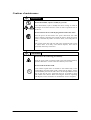
Safety Precautions- Be sure to read this section before using this product. –
Safety Descriptions
This manual describes dangers that may be caused by ignoring the cautions and the ways to
avoid those dangers. Warning labels are attached on the components that may cause danger.
“Warning” and “caution” terms are used for warning labels to describe the degree of the
danger.
This indicates a hazard that could lead to death or
WARNING serious injury in the event of improper handling.
CAUTION
This indicates a hazard that could lead to burns, injury,
or property damage in the event of improper handling.
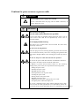
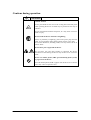
The following three types of symbols are used for warnings and cautions. The meaning of each
symbol is described below.
Attention
This symbol indicates that danger could be
(Ex)
caused if instructions are ignored. The
figure in the symbol indicates details of the (CAUTION:
danger.
Electric shock)
Prohibited
action
This symbol indicates prohibited action. The (Ex)
figure in the symbol or near the symbol
(Do not
indicates details of the prohibited action.
disassemble.)
Mandatory
action
This symbol indicates mandatory action. (Ex)
The figure in the symbol indicates details of
the mandatory action. The mandatory action
is required to avoid danger.
(Unplug)
(Description example in this manual)
Term indicating the degree of danger
Details of caution to avoid danger
CAUTION
Only plug into specified electric outlet.
Plug the power supply cable into an electric outlet on the wall
with specified voltage and power supply. Fire or electric leak may
be caused if power supply other than the one specified is used.
Symbol prompting the caution
-i-
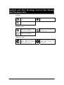
Symbols and Their Meanings Used in This Manual
and Warning Labels
Attention
Indicates the risk of an electric
shock.
Indicates the risk of smoke or
fire.
Indicates non-specific, general
Prohibited action
Indicates non-specific, general
action that is prohibited.
Do not disassemble, repair or
modify. An electric shock or
fire may result.
Indicates non-specific, general
action that is prohibited.
Mandatory action
Unplug the power supply plug
of the Autoloader from an
electric outlet. An electric
shock or fire may result.
- ii -
Indicates non-specific, general
user’s action. Follow the
instructions.
Safety Cautions
Read and understand warnings, cautions and instructions described below in order to use this
product safely. For descriptions of symbols used below, refer to the aforementioned “Safety
Description.”
General Cautions
WARNING
Do not use when smoke,
foul smell or abnormal noise are emitted.
If smoke, foul smell or abnormal noise is given off, immediately turn
off the power switch and pull out the power plug from the outlet.
Then, contact the dealer you purchased this device from or the
maintenance service company. Using the device under such
circumstances may cause a fire.
Do not insert metal strip or wire.
Do not insert foreign substances such as metal strips or wire in the air
inlet or cartridge slot as electric shock may occur.
CAUTION
Do not allow water or foreign substances into the device.
Do not place water and other liquid or pins, clips and other foreign
substances into the device because it may cause a fire, an electric
shock or failure. If any of them are placed into the device, immediately
turn the power off and pull out the power plug from the outlet. Do
not attempt to disassemble this device.Contact our dealers or
maintenance service companies.
- iii -
Cautions for power source or power cable
WARNING
Do not handle the power plug with wet hands.
Do not connect/disconnect the plug with wet hands. Otherwise, an
electric shock may occur.
CAUTION
Do not insert the plug
into the outlet other than the one specified.
Use the wall outlet of specified voltage and power source. Use of
power sources other than the one specified may cause a fire or
electrical leakage.
Do not apply starburst wiring.
This device may overheat when current exceeds the rated value,
which may cause a fire.
Do not insert the plug halfway.
Insert the plug to the end. Inserting halfway generates heat from the
loose connection and may cause a fire. The plug also generates heat
when dust or droplets adhere to the inserting part, which may cause a
fire.
Do not use the power cable other than the one specified.
Do not use the power cable other than the one attached to the device
May cause a fire when current exceeds the rated value.
In addition, to prevent from an electric shock or a fire caused by
damage of the power cable, do not perform the following actions.
・Pulling the power cable
・Pinching the power cable
・Bending the power cable
・Pouring chemicals on the power cable
・Twisting the power cable
・Placing items on the power cable
・Bundling the power cable
・Modifying, processing or repairing the power cable
・Fixing the power cable with staples, etc.
Do not use a damaged power cable (replace damaged power cable
with one with the same specification. For replacement, contact the
dealer from whom you purchased this device or a maintenance service company).
- iv -
Cautions for installing, transporting, storing, and connecting
CAUTION
Do not lift the device alone.
This device weights 18 kg. Lifting it alone may injure your back. Be
sure to transport or move the device with two persons.
Do not install in location other than the one specified.
Do not install this device in the location listed below or other than the
location specified in this manual as a fire may occur.
・Dusty place
・Humid place such as near a hot water supply
・Install where exposed to direct sunlight
・Unstable place
Do not cover the air inlet
Do not cover the fan on the back panel and air inlet on the front panel
of the device as internal temperatures will rise, resulting in a fire or
an electric shock as well as operation error.
Do not connect/disconnect the interface cable with the plug still
inserted in the outlet.
Remove
the
power
cable
from
the
outlet
before
connecting/disconnecting the interface cable. Touching cables or
connectors while the power cable is connected may lead to an electric
shock or a fire due to a short-circuit, even if the power is OFF.
Do not use an interface cable other than the one specified.
Use an interface cable specified by TD and connect it after
checking the device or connector. Using an interface cable other than
the one specified or connecting the cable to the wrong connection
point may lead to a fire due to a short-circuit.
Follow the instructions described below for handling and connecting
the interface cable.
・Do not step on the cable
・Do not place items on the cable
・Do not use the device with the cable connected loosely
・Do not use a damaged cable
・Do not use a damaged cable connector
・Be sure to lock the fastening screws
-v-
Cautions of maintenance
WARNING
Do not disassemble, repair or modify by yourself.
Never disassemble, repair or modify this device. Doing so results in
the danger of an electric shock or a fire as well as operation error of
the device.
Do not clean the device with the plug still inserted in the outlet.
Turn the power off and remove the power cable from the outlet
before cleaning. Touching parts inside the device while the power
cable is connected may lead to an electric shock, even if the power is
OFF.
Pull out the power plug and wipe with a dry cloth from time to time
to remove dust. If a dusty cord catches droplets, heat will be
generated, which may cause a fire.
CAUTION
Do not insert the connecting parts halfway.
Insert the power cable or interface cable to the end. Inserting halfway
generates heat due to a loose connection and may cause a fire.
Do not touch the broken LCD.
LCD contains liquid which is harmful to the human body. If the
liquid leaking from the broken LCD is taken into the mouse, wash it
out immediately and consult with a doctor. If the liquid adheres to the
skin or gets into the eyes, wash with water for 15 minutes or more
and consult with a doctor. When removing the LCD for separating
and disposal, contact our dealers or maintenance service companies.
- vi -
Cautions during operation
CAUTION
Caution: Suction.
Do not place hands or hair close to the cooling fan on the back panel
while operating the device as hands may be pinched or hair may be
sucked in.
Do not insert hands inside the transporter, as it may cause an electric
shock or injury.
Do not touch the device when there is lightning.
If there is possibility of lightning, pull out the power plug from the
outlet. In case lightning strikes before pulling out the power plug,
do not touch the device, including cables, as it may cause a fire or an
electric shock.
Do not allow pets to approach the device.
Do not allow pets and other animals to approach the device.
Excrement or hair entering the device may cause a fire or an electric
shock.
Do not use cellular phones, PHS (personal handy-phone system)
or pagers near the device.
Turn off cellular phones, PHS or pagers near the device as its electric
waves may cause an operation error.
- vii -
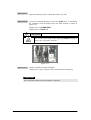
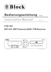
WARNING Label
WARNING labels are affixed to or around the parts where latent dangers exist so that customers
are always aware of the dangers when operating the device (therefore, do not remove or soil the
labels). If any of the labels are not affixed, peeling off or stained, contact our dealers.
FigureⅠ WARNING Label ①
FigureⅡ WARNING Label ②
①
②
②
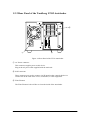
FigureⅢ Top view of the Tandberg LTO2 Autoloader
・ WARNING Label ① and ② are affixed on the front top of internal frame in advance,
because this autoloader might be converted from a standalone model into rack mount model.
- viii -
Revision History
This Revision History provides a concise publication record of this manual. It lists the manual
revision levels, release dates, and reasons for the revisions.
Document No. / Rev Level
432778
/
01
/
/
Date
2003-08-13
- ix -
Contents
Safety Precautions- Be sure to read this section before using this product. –............ i
Safety Descriptions .................................................................................................................... i
Symbols and Their Meanings Used in This Manual and Warning Labels ................................ ii
Safety Cautions ........................................................................................................................iii
General Cautions ..................................................................................................................iii
Cautions for power source or power cable........................................................................... iv
Cautions for installing, transporting, storing, and connecting............................................... v
Cautions of maintenance ...................................................................................................... vi
Cautions during operation ................................................................................................... vii
WARNING Label...................................................................................................................viii
Revision History............................................................................................................. ix
Introduction .................................................................................................................. xii
Organization of this manual ...................................................................................................xiii
Symbols used in this manual.................................................................................................. xiv
Chapter1 Tandberg LTO2 Autoloader ...................................................................... 1
1.1 Overview of theTandberg LTO2 Autoloader ......................................................................1
1.2 Names an d Functions of the Parts ....................................................................................... 2
1.2.1 Front Panel of the Tandberg LTO2. Autoloader............................................................2
1.2.2 Rear Panel of the Tandberg LTO2 Autoloader ........................................................... 4
1.2.3 Liquid Crystal Display ................................................................................................. 5
1.3 Handling Precautions .......................................................................................................... 6
1.3.1 Main Unit ..................................................................................................................... 6
1.3.2 Data Cartridges............................................................................................................. 6
1.4 Transfer or Disposal of the Device...................................................................................... 6
1.5 Contents of the Carton......................................................................................................... 7
Chapter2
Setup ............................................................................................................ 8
2.1 Preparation Before Use ....................................................................................................... 8
2.2 SCSI Cable Connections ..................................................................................................... 9
2.3 AC Power Cable Connection............................................................................................. 10
2.4 Switching ON the Power Switch and the Power-On Sequence......................................... 12
2.5 SCSI ID Setting................................................................................................................. 12
2.6 Starting and Closing the System ....................................................................................... 13
Chapter 3
Operation ................................................................................................. 14
3.1 Removal of the Magazine ................................................................................................. 14
3.2 Loading the Magazine....................................................................................................... 15
3.3 Loading the Cartridge........................................................................................................ 16
3.3.1 Loading to the Magazine............................................................................................ 16
3.3.2 Loading to the Fixed Slots ......................................................................................... 17
3.4 Removal and Insertion of the Cartridges........................................................................... 19
3.4.1 Removal from and Insertion to the Magazine ............................................................ 19
3.4.2 Removal from and Insertion to the Fixed Slots.......................................................... 20
3.5 Operation of the Panel Keys.............................................................................................. 21
3.5.1 Organization of the Front Panel Switches .................................................................. 21
3.5.2 Functions of the Switches .......................................................................................... 21
3.5.3 Slot Logical Numbers................................................................................................. 21
3.5.4 Panel Operation Procedure......................................................................................... 22
3.5.5 Menu Tree .................................................................................................................. 24
-x-
3.6 Setting the SCSI ID ........................................................................................................... 26
3.6.1 Checking the SCSI ID ................................................................................................ 26
3.6.2 Changing the SCSI ID................................................................................................ 27
3.7 Using the Emergency Release Key ................................................................................... 30
Chapter 4
Cartridges................................................................................................. 31
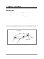
4.1 Cartridges .......................................................................................................................... 31
4.1.1 Data Cartridge ............................................................................................................ 32
4.1.2 Cleaning Cartridge ..................................................................................................... 32
4.2 Write-Protect Switch ......................................................................................................... 33
4.3 Bar Code Label.................................................................................................................. 34
4.4 Handling Precautions ........................................................................................................ 35
4.4.1 Usage Precautions ...................................................................................................... 35
4.4.2 General Precautions.................................................................................................... 35
4.4.3 Standards for Prohibition of Use ................................................................................ 36
4.4.4 Service Life ................................................................................................................ 36
4.4.5 Storage of Data Cartridges ......................................................................................... 36
Chapter 5
Daily Maintenance................................................................................... 37
5.1 Cleaning ............................................................................................................................ 37
5.1.1 Cleaning of the Drive Head........................................................................................ 37
5.1.2 Cleaning the Roller inside of the transporter.............................................................. 39
5.1.3 Cleaning of the Main Unit.......................................................................................... 51
5.1.4 Cleaning of the magazine........................................................................................... 52
5.1.5 Cleaning of the cartridge ............................................................................................ 52
5.2 Movement and Shipping of the Autoloader ...................................................................... 53
Chapter 6
Troubleshooting ....................................................................................... 54
6.1 Other Matters to Check ..................................................................................................... 60
6.2 When Requesting Maintenance......................................................................................... 60
Appendix A Specifications ........................................................................................ 61
Appendix B
Optional Items and Supplies ............................................................... 63
Appendix C Error Code............................................................................................ 64
- xi -
Introduction
Tandberg LTO2 Autoloader is an external memory device that has been developed for the
file systems of servers and other equipment. This large capacity, high-performance streaming
cartridge tape device is designed for use in medium intermediate to top-level computer systems.
This manual describes the overview, operation, maintenance method, regular maintenance, and
troubleshooting of this device so as to avoid maintenance faults.
Please keep this manual in a safe place so that it may be easily referred to when necessary.
- xii -
Organization of this manual
This section describes the organization of this manual and an overview of each chapter. Use it
when you would like to find out something about this device.
Chapter 1 Tandberg LTO2 Autoloader
This chapter describes the features of the Autoloader as well as the package contents and
the names of the parts. It also covers precautions for handling and storage. (See the
description at the beginning of the manual concerning precautions for the safe handling of
the device.)
Chapter 2
Setup
This chapter presents a step-by-step explanation of the procedure from the connection of
the Autoloader to a server or workstation all the way to bringing it up to a usable
condition. The procedure should be followed for proper installation. There is also a
description of the rack mounting method.
Chapter 3
Operation
In this chapter, a description is provided of the TD Autoloader LTO2 operation, front
panel menu organization, and the method of inserting the data cartridge.
Chapter 4
Cartridges
This chapter describes the method of handling the data cartridge that is used in the
Autoloader as well as handling precautions.
Chapter 5
Daily Maintenance
The cleaning method and precautions to take when moving and storing the Tandberg LTO2
Autoloader are described so that the Autoloader can be maintained in the best condition
for whenever it is used.
Chapter 6
Troubleshooting
Should the Autoloader fail to operate properly, please check the details described in this
chapter before assuming a breakdown has occurred. If the problem persists, please
request servicing from a repair company.
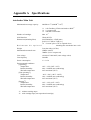
Appendix A Specifications
The specifications of the Tandberg LTO2 Autoloader and the data cartridge are listed here.
Appendix B
Optional Items and Supplies
Optional items and supplies are listed here.
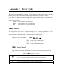
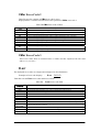
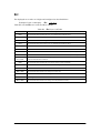
Appendix C
Error Code
This section lists the Autoloader error codes and treatment method.
- xiii -
Symbols used in this manual
Symbols used in this manual
The following symbols are used to indicate cautions or tips for operations. (For symbols related
to safety precautions, please refer to the descriptions aforementioned.)
Important
Indicates handling methods of this product, software operational instructions,
or special notes.
Tip
Indicates helpful and useful information.
- xiv -
Chapter1 Tandberg LTO2 Autoloader
Some preliminary information about the Tandberg LTO2 Autoloader is presented here before
installation and handling.
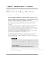
1.1 Overview of the Tandberg LTO2 Autoloader
This is a high-performance, high-capacity data storage device that is connected to the supported
host to provide additional host storage. The Autoloader is designed to run an unattended backup
and is furnished with the following functions.
・ The LTO2 Autoloader has one built-in LTO Ultrium tape drive that reads and writes data
and a robot mechanism that handles up to 10 cartridges (w/BCR*1 : up to 9).
・ The LTO2 Autoloader is equipped with a Ultra160 Low Voltage Differential(LVD) interface
and functions as a device having two different IDs on a single SCSI bus.
・ The maximum transfer rate (at the time of reading/writing) of the LTO2 Autoloader when
operating in the non-compression mode is 35 MB/s. The maximum transfer rate (at the
time of reading/writing) in the compression mode (with a compression of 2 times)
is 70 MB/s.
・ The amount of data that can be stored on a LTO2 data cartridge is a maximum of 200 GB
in the non-compression mode and 400 GB (with a compression of 2 times) in the
compression mode. The Tandberg LTO2 Autoloader permits the storage of a maximum
of 2 TB of data on 10 LTO2 data cartridges in the non-compression mode and a maximum
of 4 TB (with a compression of 2 times) in the compression mode.
・ The optional Tandberg LTO2 Autoloader Rack Mounting Kit is required to mount the
(rack mount type of the) Tandberg LTO2 Autoloader into a rack*2
・ The optional Tandberg LTO2 Autoloader Rack Mounting Kit allows two (rack mount
type of the) Tandberg LTO2 Autoloader units to be mounted with only one kit.
・ A vacant 5U portion of space is required to mount the (rack mount type of the) Tandberg
LTO2 Autoloader in a rack.
Important
1*: Performance of the LTO2 Autoloader including Bar Code Reader model
We can provide you the Tandberg LTO2 Autoloader with the Bar Code
Reader which hereafter called Autoloader w/BCR.TheAutoloader w/BCR
requires a free slot used to swap cartridge during the inventory scan process.
Thus the maximum cartridge capacity of the Autoloader w/BCR is changed
from 10 to 9. But if you will prefer to use 10 cartridges, the BCR function
will be changed disable.
In this case, please contact your nearest Customer Support Center.
*2: Tandberg LTO2 Autoloader is a standalone model. To mount this autoloader into a rack,
you must convert this autoloader to a rack mount model. This is easily accomplished by using the
LTO2 Autoloader Rack Mounting Kit.
-1-
1.2 Names and Functions of the Parts
This section describes the names and functions of the Tandberg LTO2 Autoloader parts.
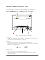
1.2.1 Front Panel of the Tandberg LTO2 Autoloader
②
①
⑥
⑦
③
④
⑤
Figure 1-1 Front Panel of the LTO2 Autoloader
① Front door
This door prevents the intrusion of foreign objects. While the power is ON, unlock the door
lock with the door lock key supplied with the main unit.
② Key lock
The front door is locked with the door lock key supplied with the main unit.
Pushing in the key and turning it clockwise 90 degrees will release the lock. The unit should
normally be used with the door locked.
Door Locked.
Door Open.
③ Power switch
This switch switches the power of the Autoloader on and off.
A press on the right side ( | ) switches the power ON and a press on the left side (○)
switches the power OFF.
-2-
④ Liquid Crystal Display
This liquid crystal display (LCD) is organized in 2 lines of 10 characters, and 11 icon
characters. It displays the status of the Autoloader, menus, and error information.
⑤ Alarm LED
This LED lights (in red) should some kind of fault arise in the Autoloader.
⑥ Power LED
This LED lights (in green) when the power is supplied and the power switch is ON; it is
unlit when the power is OFF.
⑦ Panel keys
・
(arrow) key : Moves forward through the menu.
・
(arrow) key : Moves backward through the menu.
・ ENTER key
: Defines and executes the displayed menu or operation
command.
・ ESCAPE key : Cancels the execution of the selected command, or returns to
the previous screen of the selected menu.
-3-
1.2.2 Rear Panel of the Tandberg LTO2 Autoloader
③
①
②
Figure 1-2 Rear Panel of the LTO2 Autoloader
① AC Power connector
This connector supplies power to this device.
Plug in the AC power cable supplied with the main unit.
② SCSI connector
These connectors are used to connect a SCSI interface that controls this device.
Connect the SCSI cable of the server, workstation, or other equipment.
③ Filter Element
The Filter Element is the air filter to clean the inside of the Autoloader.
-4-
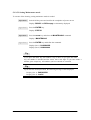
1.2.3 Liquid Crystal Display
The display is a liquid crystal display (LCD) that indicates the status of the Autoloader,
menus, and error information. The display is organized in 2 lines, each able to display up
to 10 characters.
Lighting of any of the 11 icon characters indicates the corresponding slot number when a
cartridge is housed in a magazine and fixed slots. The lock symbol will also light when
the front door is locked with the door lock key supplied with the main unit. The icon will
cease to be illuminated when the door lock is unlocked.
Figure 1-3 Liquid Crystal Display (LCD)
-5-
1.3 Handling Precautions
To operate this device properly, please observe the following precautions.
1.3.1 Main Unit
●
Cooling fans are attached to the rear panel of the Autoloader. Do not use the unit in
places where the fans will be obstructed or there is poor air circulation. The
Autoloader should not be stored or used in extremely hot locations or in locations
having severe temperature changes.
●
The Autoloader is built with precision electronic components. Do not subject the
Autoloader to shock or either use or store it in locations that are exposed to vibration.
●
Do not use or store the Autoloader in locations where chemical vapors are dispersed
in the air or where the unit will come into contact with chemicals.
●
Do not move or transport the Autoloader while the power is ON.
●
Do not use or store the Autoloader with a heavy object on top of it.
●
Do not switch off the power while the Autoloader is operating.
●
To insert or remove a magazine, first check that the Autoloader is in a condition that
will allow insertion or removal of the magazine.
●
Only insert a cartridge into a magazine, nothing else.
Be sure to use the (rack mount) Tandberg LTO2 Autoloader mounted in a rack .
(Rack mounting requires the Tandberg LTO2 Autoloader Rack Mounting Kit.)
●
1.3.2 Cartridges
●
The data cartridge that should be used is the TD LTO1 Data Cartridge (TD P/N:
432630-1) and the TD LTO2 Data Cartridge (TD P/N:
432744).
●
The cleaning cartridge that should be used is the TD LTO Universal Cleaning Cartridge (TD P/N:
432631)
●
See Chapter 4 for other precautions.
1.4 Transfer or Disposal of the Device
●
When disposing of this device along with the consumables and accessories, please
follow the national and municipal guidelines for disposal.
●
When transferring this device to another party, please include all items including this
manual.
-6-
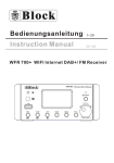
1.5 Contents of the Carton
Open the carton and check that all of the following items are included. In the unlikely event that
something is missing or damaged, please contact your store of purchase.
Roller cleaner set
Main unit
Filter Element
Installation and
User’s Manual
AC power cable
Emergency release key
(x 1)
Preparation guide before powering
on the Autoloader
Terminator (dual LVD/SE)
Door lock key
(x 2)
Check the “Lock Block” condition
Figure 1-4 Contents of the Carton
Important
・The carton and cushioning material will be used when moving or storing the
device and should be kept safely for such times.
・Should this device be transferred to another party, please be sure to include
this instruction manual.
-7-
Chapter2 Setup
This chapter describes the procedure for connecting the Autoloader to a basic processing device
such as a server or workstation.
Important
Maintenance personnel will perform the rack installation or removal work for
the Tandberg LTO2 Autoloader.
2.1 Preparation Before Use
Before using the Autoloader, remove the transporter locking screw that is a type of thumbscrew
located at the left side of the decorative cover.
Important
Remove the transporter locking screw before switching ON the power switch.
Switching ON the power while the transporter locking screw is still attached
could result in damage to the Autoloader.
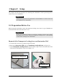
Removal of the Transporter Locking Screw and Instruction TAG
1. To loosen this screw turn to counterclockwise by hand.
2. Remove the Instruction TAG with the Transporter Locking Screw (see figure 2-1).
3. As the Transporter Locking Screw will be needed to ship or move the Autoloader, insert
it into the hole and tighten to keep it (see figure 2-2).
Transporter Locking Screw
Instruction TAG
Figure 2-1 Removal of the Transporter Locking Screw and Instruction TAG
-8-
Figure 2-2 Storing the Transporter Locking Screw for later use
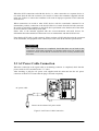
2.2 SCSI Cable Connections
CAUTION
Before starting the installation of this device, be certain to
unplug the power plug of the server, workstation, or other
processing equipment. Working on the unit while the power
plug is left connected to the power outlet could result in
electrical shock.
The Autoloader is connected to the server/workstation (or other SCSI device) with a SCSI cable.
The SCSI connector of the Autoloader is located on the rear panel.
To the next SCSI device
From the host computer
Terminator
Figure 2-3 SCSI Cable Connections
-9-
When the SCSI connections end with this device (i.e., when connection to a separate device is
not made from the left-side connector), be certain to connect the terminator supplied with the
main unit. Failure to connect the terminator will result in improper operation of all connected
SCSI devices.
When connections are made to other SCSI devices with the Autoloader connected in an
intermediate position, connection to the next SCSI device is made from the left-side connector.
Be certain to attach the terminator to the SCSI device positioned at the farthest end of the chain
of devices that are connected by SCSI cable.
Please refer to the manuals supplied with the server/workstation and SCSI devices for
information about the method of connection to server/workstations and other SCSI devices.
Note that the SCSI cable is sold separately. Please purchase a SCSI cable that suits the connectors
of the Autoloader, the equipment to be connected, as well as the SCSI interface specifications.
Important
Once cable connections are completed, check that there are no kinks in the
connections. SCSI cable connectors are equipped with screws for securing the
connection. Please check that the connectors have been securely fastened with
the screws.
2.3 AC Power Cable Connection
When the connection to the signal cable or terminating connector is completed, check that the
power switch is OFF (switched to the " { " side).
After checking it, plug the AC power cord supplied with the main unit into the AC power
connector of this device. Ensure that the plug is inserted completely.
AC power cable
Connect to the external AC power outlet
Figure 2-4 AC Power Cable Connection
- 10 -
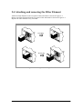
2.4 Attaching and removing the Filter Element
Attach the Filter Element to the rear panel of the Autoloader as shown in Figure 2-5.
Remove the Filter Element from the rear panel of the Autoloader as shown in Figure 2-5.
Replace the Filter Element every 6 months.
Attaching
Removing
Figure 2-5 Attaching and removing a Filter Element
- 11 -
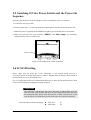
2.5 Switching ON the Power Switch and the Power-On
Sequence
Switching ON the power of the Autoloader executes an automatic power-on sequence.
1. Connect the AC power cable.
2. Press the right side ( | ) of the Autoloader front panel power switch to switch the power ON.
3. When the power is supplied, the POWER LED lights in green and the power-on test starts.
4. When the power-on test ends normally, "READY" and "DRV empty" are alternately
displayed on the top level of the LCD.
Power switch
Figure 2-6 Powering on the LTO2 Autoloader
2.6 SCSI ID Setting
Please check that the SCSI ID of the Autoloader is not already being used by a
server/workstation or another SCSI device. (Prior to shipping from the factory, the SCSI ID of
the Autoloader was set as described below.)
See "3.6 Setting the SCSI ID" for information about how to check the SCSI IDs that have been
set and for the method of changing them when required.
Important
The Autoloader and the tape drive must each have an independent SCSI ID.
This device has a specification that does not allow duplication of the tape drive
and Autoloader IDs. Please check that the IDs of other SCSI devices on the
same SCSI bus do not duplicate the IDs of the tape drive and the Autoloader.
SCSI ID at time of factory shipping
●
●
- 12 -
Tape drive
Autoloader
:
:
(1)
(0)
2.7 Start and Shutdown of the System
When the SCSI ID settings have been completed, switch on the power of the server/workstation
and the other devices and start the system.
To start the system, switch ON the power in the order of the Autoloader (along with the
peripherals connected to the server/workstation) and then the server/workstation.
Important
If the data cartridge is loaded into the tape drive before starting the system, the
reading/writing of data recorded on the data cartridge may not be performed
properly.
To shut down the system, switch OFF the power in the order of the server/workstation and then the
Autoloader (along with the peripherals connected to the server/workstation).
Important
・Before shutting down the system, check that a data cartridge is not loaded in the
tape drive. If the system is shut down while the data cartridge is still loaded in
the tape drive, the next time the system is started, the reading/writing of data
recorded on the data cartridge may not be performed properly or this could
cause damage to the data cartridge or this device.
・Do not shut down or restart the system while this device is operating. Check
that this device is stopped before closing down or restarting the system.
Important
If an error message is shown as "Unreadable Media" on the PC console’s
screen without front panel LED lighting solid red during the following
operations, Inventory, Erase, Backup, Restore and etc., please retry the same
operation. Also if the cartridge remains in the drive, please eject the cartridge
from the drive by manual operation (refer “3.5 Operation of the Panel Keys”)
before retrying the operation.
- 13 -
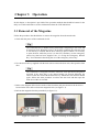
Chapter 3 Operation
In this chapter, a description is provided of the operation methods that should be known for the
daily use of the Autoloader as well as information about the LCD indications.
3.1 Removal of the Magazine
Follow the procedure described below to remove the magazine from the Autoloader.
1. Check that the power of the Autoloader is ON.
Tip
The Autoloader has a double locking mechanism comprising a door lock and
an electronic lock. When the power is in the OFF condition, the electronic lock
is activated by a solenoid and the door cannot be opened. When it is necessary
to open the door while the power is in the OFF condition, use the emergency
release key that has been supplied. See “3.8 Using the Emergency Release
Key” for information describing the use of the emergency release key.
2. Use the door lock key supplied with the main unit to release the door lock, then open the front
door.
Tip
The Autoloader is designed so that the electronic lock operation will again be
activated if the front door is not opened within 10 seconds following the
release of the door lock with the door lock key. Should the door become locked
again, follow this same procedure to release the door lock and then open the
front door within 10 seconds.
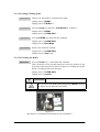
3. Refer to the diagram affixed to the inside of the front door and press down on the lock lever
located at the lower left to release the magazine lock (see figure 3-1).
4. Pull out the magazine that has protruded (see figure 3-2).
Figure 3-1 Lock Lever
Figure 3-2 Pulling out the Magazine
- 14 -
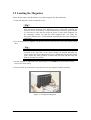
3.2 Loading the Magazine
Follow the procedure described below to load the magazine into the Autoloader.
1. Check that the power of the Autoloader is ON.
Tip
The Autoloader has a double locking mechanism comprising a key operated
door lock and an electronic lock. When the power is in the OFF condition, the
electronic lock is activated by a solenoid and the door cannot be opened. When
it is necessary to open the door while the power is in the OFF condition, use
the emergency release key that has been supplied. See “3.8 Using the
Emergency Release Key” for information describing the use of the emergency
release key.
2. Use the door lock key supplied with the main unit to release the door lock, then open the front
door.
Tip
The Autoloader is designed so that the electronic lock operation will again be
activated if the front door is not opened within 10 seconds following the
release of the door lock with the door lock key. Should the door become locked
again, follow this same procedure to release the door lock and then open the
front door within 10 seconds.
3. Set the magazine as indicated in the figure and press the PUSH mark portion back until it
locks with a click sound.
4. Close the front door and lock it using the door lock key supplied with the main unit.
Figure 3-3 Loading the Magazine
- 15 -
3.3 Loading the Cartridge
This section describes the method of loading the cartridges.
In this device the slot numbers are assigned to the magazine and internal fixed slots as
illustrated below.
(Top of device)
10
7
9
6
8
5
Rear of device
4
Front of device
3
Drive
2
1
Figure 3-4 Slot Logical Numbers
Important
The Tandberg LTO2 Autoloader w/BCR requires a free slot used to swap
cartridge during the inventory scan process. Thus the maximum cartridge
capacity of the Autoloader w/BCR is changed from 10 to 9 and you can not
use slot 10 that is a free slot. But if you prefer to use 10 cartridges, the
BCR function neet be disabled.
In this case, please contact your nearest Customer Support Center.
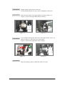
3.3.1 Loading to Magazine
A maximum of 7 cartridges can be loaded into the magazine.
Follow the procedure described below to load the cartridges into the magazine.
1. Load the cartridges into the magazine in the proper orientation as shown in the figure 3-5.
(The insertion direction is marked on the label on the side of the magazine.)
2. A "click" locking sound will be heard when the cartridge is inserted to the back. Up to seven
cartridges can be mounted on a magazine.
Perform the following procedures to mount a cartridge on a magazine:
Tip
When inserting the cartridge, be certain to push it in until it locks with a
"click." If the cartridge is not properly locked, it could fall out from the
magazine.
- 16 -
Figure 3-5 Loading the Magazine
3.3.2 Loading to the Fixed Slots
A maximum of 3 cartridges can be loaded to the fixed slots inside the Autoloader.
Operation of the Autoloader front panel keys permits automatic loading of the cartridges from
the magazine to the fixed slots. Loading is possible between the following slots at this time.
Slots involved with cartridge movement when loading
Slot 5
Slot 6
Slot 7
→
→
→
Slot 8
Slot 9
Slot 10.
Important
For using the Tandberg LTO2 Autoloader w/BCR's optional
In using the TD LTO2 Autoloader w/BCR, slot 10 must be a free slot
used to swap a cartridge during the inventory scan process. When you load
the 2 cartridges to the fixed slots, i.e. slot 8 and slot 9, you can insert the
cartridges into slot 5 and slot 6 only.
Operation Examples
The operation procedure and display indications are described when loading the cartridges of
slot numbers 5 to 7 within the magazine to slot 8 to 10 among the fixed slots. See "3.5
Operation of the Panel Keys" for information about detailed panel operations.
Operation 1
Switch ON the power and wait for the completion of the power-on test.
Display: "READY" and "DRV empty" are alternately displayed.
- 17 -
Operation 2
Press the "ENTER" key.
Display: STATUS
Operation 3
Press the "arrow" key and select the LOAD command.
Display: LOAD
Operation 4
Press the "ENTER" key and define the command.
Display: Load Drv?
Operation 5
Press the "arrow" key and select "Load Slt?" .
Display: Load Slt?
Operation 6
Press the "ENTER" key and execute the command.
Display: Complete (when the command ends normally.)
Err. xxxxxx (when an error occurs. xxxxxx is the error code.)
Tip
• Loading by command is valid only when slots 8 to 10 among the fixed slots
are all vacant slots.
• When loading by command is executed, all cartridges housed in slots 5 to 7
within the magazine are moved to fixed slots.
Important
For using the Tandberg LTO2 Autoloader w/BCR
In using the LTO2 Autoloader w/BCR, slot 10 must be a free slot used
to swap a cartridge during the inventory scan process. When you load the 2
cartridges to the fixed slots, i.e. slot 8 and slot 9, you can insert the cartridges
into slot 5 and slot 6 only. If a cartridge is in slot 7, loading command is
failed and error message of "S10 forBCR" is displayed on the LCD.Then,
you remove the cartridge fro slot7 manually, and retry the loading command.
- 18 -
3.4 Removal and Insertion of the Cartridges
The method by which cartridges are removed and inserted is described here.
3.4.1 Removal from and Insertion to the Magazine
1. Hold the magazine body steady and press the center portion of the cartridge. A "click" sound
is heard and the lock is released.
2. Remove the cartridge.
Figure 3-6 Removal and Insertion of Cartridges (7-Slots)
Tip
When removing or inserting cartridges, keep your finger against the cartridge
when pressing on the center portion so that the cartridge does not fall out.
- 19 -
3.4.2 Removal from and Insertion to the Fixed Slots
Operation 1
Remove the cartridges that are housed in the fixed slots (i.e., slot 8 to
10). (The cartridges will move to slot 5 to 7 within the magazine at this
time.)
Operation 2
Reload a magazine into the main unit that has vacant slots for slot 5 to
7.
Operation 3
Lock the front door and wait for "READY" to be displayed.
Operation 4
Press the "ENTER" key.
Display: STATUS
Operation 5
Press the "arrow" key and select the EJECT command.
Display: EJECT
Operation 6
Press the "ENTER" key and define the command.
Display: Eject Drv?
Operation 7
Press the "arrow" key and select "Eject Slot?" .
Display: Eject Slot?
Operation 8
Press the "ENTER" key and execute the command.
Display: Complete (when the command ends normally.)
Err. xxxxxx (when an error occurs. xxxxxx is the error code.)
Operation 9
When required, remove the magazine and remove the cartridges of slot
5 to 7 which have been moved.
Tip
•Ejecting by command is valid only when slot numbers 5 to 7 among the
magazine slots are all vacant slots.
•When ejecting by command is executed, all cartridges housed in slot numbers
8 to 10 within the fixed slots are moved to the magazine.
- 20 -
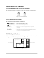
3.5 Operation of the Panel Keys
3.5.1 Organization of the Front Panel Switches
The arrangement of switches as viewed from in front of the front panel is as illustrated below.
ESCAPE
ENTER
Figure 3-7 Front Panel Switches
3.5.2 Functions of the Switches
The functions of the various switches are described below.
key(arrow key)
:
Moves forward through the menu.
key(arrow key)
:
Moves backward through the menu.
ENTER key
:
Defines and executes the displayed menu or operation
command.
ESCAPE key
:
Cancels the execution of the selected command, or returns to
the previous screen of the selected menu.
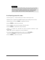
3.5.3 Slot Logical Numbers
In the Autoloader, logical numbers such as the following are assigned to the slots that house the
cartridges upon execution of the operation command.
(Top of device)
10
7
9
6
8
5
Rear of device
4
3
Drive
2
1
Figure 3-8 Slot Logical Numbers
- 21 -
Front of device
Important
The LTO2 Autoloader w/BCR requires a free slot used to swap cartridge
during the inventory scan process. Thus the maximum cartridge capacity of
the LTO2 Autoloader w/BCR is changed from 10 to 9. But if you prefer
to use 10 cartridges, the BCR function will need to be changed disabled.
In this case, please contact your nearest Customer Support Center.
3.5.4 Panel Operation Procedure
1. Press the right side ( | ) of the Autoloader power switch to switch the power ON.
2. When the power is supplied, the POWER LED lights in green and the power-on test starts.
3. When the power-on test ends, "READY" is displayed on the LCD.
4. Press the ENTER key and enter the main menu.
5. Press the arrow key and select the command. (The menu scrolls.)
6. Press the ENTER key and define the selected command.
7. Refer to “3.5.5 Menu Tree” and follow the system of operation commands to repeat
aforementioned
Steps 5 and 6, select the command to be executed, and define it.
8. To cancel the defined command during this procedure, press the ESCAPE key.
(A press of the ESCAPE key results in a return to the previous menu.)
9. Press the ENTER key and execute the menu.
- 22 -
Operation Examples
The operation procedure and LCD indications are described below when loading the cartridge
housed in slot 7 into the drive.
Operation 1
Switch ON the power and wait for the completion of the power-on test.
Display: "READY" and "DRV empty" are alternately displayed.
Operation 2
Press the ENTER key.
Display: STATUS
Operation 3
Press the arrow key and select the "LOAD" command.
Display: LOAD
Operation 4
Press the ENTER key and define the command.
Display: Load Drv?
Operation 5
Press the ENTER key and define the command.
Display: Frm Slt 1?
Operation 6
Press the arrow key and select "Slt 7".
Display: Frm Slt 7?
Operation 7
Press the ENTER key and execute the command.
Display: Complete (when the command ends normally.)
Err. xxxxxx (when an error occurs. xxxxxx is the error code.)
- 23 -
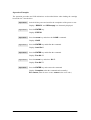
3.5.5 Menu Tree
1
Main Menu
READY
STATUS
2
EJECT
UNLOCK
LOAD
SCSI ID
RETRY MODE
MAINTENANC
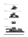
Menu Commands
1) STATUS
(Permits a check of the different types of status.)
STATUS
Slt 1?
Slt 10?
Drive ?
Magazine ?
2) EJECT
(Permits ejecting a cartridge from the drive and houses the cartridge in an empty slot.)
EJECT
Eject Drv?
To Slt 1?
Eject Slt?
To Slt 10?
Important
Do not use this command during a reading / writing operation.
3) UNLOCK
(Cancels the front door software key lock.)
UNLOCK
Unlock?
- 24 -
4) LOAD
(Permits loading a cartridge from an arbitrary slot to the drive.)
LOAD
Load Drv?
Frm Slt 1?
Load Slt?
Frm Slt10?
5) SCSI ID
(Permits setting, changing, and checking of the drive and Autoloader SCSI ID.)
SCSI ID
View ID?
Set ID?
Lib. ID?
Lib.ID 0?
Drv. ID?
Lib.ID 15?
Drv.ID 0?
Drv.ID 15?
6) RETRY MODE
RETRY MODE
Not Support
7) MAINTENANC
(You can check or change the CLNROL function.)
MAINTENANC
CLEAN ROL?
RCLN MODE?
View ?
Disable?
RtyCnt 10?
Revision?
Set ?
Lib.Rev?
RtyCnt 15?
RtyCnt 20?
- 25 -
BCR MODE?
Drv.Rev?
View ?
RtyCnt 25?
Set ?
Disable?
Enable?
3.6 Setting the SCSI ID
This command sets the SCSI ID of the Autoloader in conjunction with SCSI devices such as the
server/workstation that is to be connected.
The following SCSI IDs are assigned to this device as default values prior to shipping from the
factory.
SCSI IDs at time of factory shipping:
• Tape drive
• Autoloader
: (1)
: (0)
Important
The Autoloader and the tape drive must each have an independent SCSI ID.
This device has a specification that does not allow duplication of the tape drive
and Autoloader IDs. Please check that the IDs of other SCSI devices on the
same SCSI bus do not duplicate the IDs of the tape drive and the Autoloader.
Checking the SCSI ID and the method of changing it are described in this section.
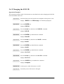
3.6.1 Checking the SCSI ID
Operation 1
Switch ON the power and wait for the completion of the power-on test.
Display: "READY" and "DRV empty" are alternately displayed.
Operation 2
Press the ENTER key.
Display: STATUS
Operation 3
Press the arrow key and select the "SCSI ID" command .
Display: SCSI ID
Operation 4
Press the ENTER key and define the command.
Display; View ID?
Operation 5
Press the ENTER key and define the command.
Display: L.0 D.1
Tip
When checking the SCSI ID, the Autoloader is displayed as "L" and the tape
drive as "D".
- 26 -
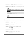
3.6.2 Changing the SCSI ID
Operation Example 1
The operation procedure and LCD indications are described below when changing the SCSI ID
of the Autoloader from 0 to 1.
Operation 1
Switch ON the power and wait for the completion of the power-on test.
Display: "READY" and "DRV empty" are alternately displayed.
Operation 2
Press the ENTER key.
Display: STATUS
Operation 3
Press the arrow key and select the "SCSI ID" command.
Display: SCSI ID
Operation 4
Press the ENTER key and define the command.
Display: View ID?
Operation 5
Press the arrow key and select the "Set ID" command.
Display: Set ID?
Operation 6
Press the ENTER key and define the command.
Display: Lib.ID?
Operation 7
Press the ENTER key and define the command.
Display: Lib. ID 0?
Operation 8
Press the arrow key and select the "Lib. ID1" command.
Display: Lib. ID 1?
Operation 9
Press the "ENTER" key and define the command.
Display: Complete
Operation 10
Set the power switch of this device to OFF.
Operation 11
Switch the power of this device ON again.
- 27 -
Operation 12
Wait for the completion of the power-on test.
Display: "READY" and "DRV empty" are alternately displayed.
Operation 13
Check the "READY" display and then switch on the power of the
server/workstation and the other devices to restart the system.
Tip
When changing the SCSI ID, the Autoloader is displayed as "Lib." and the
tape drive as "Drv."
Important
When changing the SCSI ID of this device, be certain to execute a restart of
this device, the server/workstation, and any other devices. Note that the restart
of the server/workstation and the other devices should be executed after
checking the "READY" display of this device.
Tip
See "2.6 Starting and Closing the System" for information about the power-on
sequence.
Operation Example 2
The operation procedure and LCD indications are described below when changing the SCSI ID
of the tape drive from 1 to 5.
Operation 1
Switch ON the power and wait for the completion of the power-on test.
Display: "READY" and "DRV empty" are alternately displayed.
Operation 2
Press the ENTER key.
Display: STATUS
Operation 3
Press the arrow key and select the "SCSI ID" command.
Display: SCSI ID
Operation 4
Press the ENTER key and define the command.
Display; View ID?
Operation 5
Press the arrow key and select "Set ID" command.
Display: Set ID?
- 28 -
Operation 6
Press the ENTER key and define the command.
Display; Lib.ID?
Operation 7
Press the arrow key and select "Drv. ID?" command.
Display: Drv. ID?
Operation 8
Press the ENTER key and define the command.
Display; Drv. ID 0?
Operation 9
Press the arrow key and select "Drv. ID 5" command.
Display: Drv. ID 5?
Operation 10
Press the ENTER key and define the command.
Display: Complete
Operation 11
Set the power switch of this device to OFF.
Operation 12
Switch the power of this device ON again.
Operation 13
Wait for the completion of the power-on test.
Display: "READY" and "DRV empty" are alternately displayed
Operation 14
Check the "READY" display and then switch on the power of the
server/workstation and the other devices to restart the system.
Important
When changing the SCSI ID of this device, be certain to execute a restart of
this device, the server/workstation, and any other devices. Note that the restart
of the server/workstation and the other devices should be executed after
checking the "READY" display of this device.
- 29 -
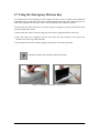
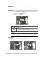
3.7 Using the Emergency Release Key
As touched upon at the beginning of this chapter, this device has a double lock mechanism
comprising a key operated door lock and a solenoid operated electronic lock. When the power is
in the OFF condition, the electronic lock is activated and the door cannot be opened.
To release the door lock at the time of a power outage or emergency, release the electronic lock
by following this procedure.
1. Release the door lock as usual by using the door lock key supplied with the main unit.
2. Insert the release key (supplied with the main unit) into the electronic lock release key
insertion slot at the top of the main unit.
3. Press down the electronic lock key lightly and open the door at the same time.
Emergency Release Key supplied with the main unit
Figure 3-9 Using the Emergency Release Key
- 30 -
Chapter 4 Cartridges
4.1 Cartridges
The Tandberg LTO2 Autoloader uses the following types of LTO cartridges.
・ TD P/N : 432744
LTO2 Data Cartridge
・ TD P/N : 432630-1 LTO1 Data Cartridge
・ TD P/N : 432631
LTO Universal Cleaning Cartridge
To ensure that your Tandberg LTO2 Autoloader conforms to our specifications for reliability, use
only the above cartridges. Below figure shows the overview of a cartridge and its components.
Insertion guide
Leader pin
Cartridge door
Write-protect switch
Label area
Figure 4-1 LTO Cartridge
- 31 -
4.1.1 Data Cartridge
The Data Cartridge contains 1/2-inch MP (metal-particle) tape.
The cartridge door protects the tape from contamination when the cartridge is out of the
drive.
The write-protect switch prevents data from the accidental erasure of data.
The label area provides a location for placing a label. A label that extends outside of the
recessed area can cause loading problems in the tape drive.
The insertion guide is a large, notched area that prevents users from inserting the cartridge
incorrectly.
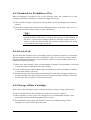
4.1.2 Cleaning Cartridge
The Tandberg LTO2 Autoloader itself determines when a drive head needs to be cleaned. It
alerts you displaying "REQ clean" on the LCD. The cleaning cartridge is valid for 50 uses. .
Important
If you insert a cleaning cartridge when the tape drive does not need to be
cleaned or if you insert a cleaning cartridge that has expired, the tape drive
will eject the cleaning cartridge automatically.
- 32 -
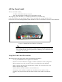
4.2 Write-Protect Switch
Each LTO data cartridge has a write-protect switch that can be used to prevent accidental
erasure of data. Before inserting the data cartridge into the tape drive, position the write-protect
switch on the front of the cartridge. The position of the write-protect switch is shown below.
・ Move the write-protect switch to the left to disable write protection.
This means that data can be written to the data cartridge unless software write-protect
is in effect..
・ Move the write-protect switch to the right to enable write protection.
This means that data can not be written to the data cartridge.
Write-Protect Switch
Write Protect
Write Enable
Figure 4-2 Setting the Write-protect Switch
- 33 -
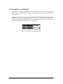
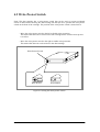
4.3 Bar Code Label
The bar code label contains;
・ A volume serial number that you can read.
・ A bar code label that the Tandberg LTO2 Autoloader can read.
When appling a bar code labels to a cartridge position the bar code label only
in the recessed label area (see below figure). A bar code label that extends outside of this
recessed area can cause reading problems in the internal LTO drive or the robotics of the TD LTO2 Autoloader.
Sample Bar Code Label on the cartridge
Figure 4-3 Sample Bar Code Label on the Cartridge
Tip
Do not place any type of mark on the white space area at either end of the bar
code. A mark in this area may prevent the Tandberg LTO2 Autoloader from
reading the bar code label.
Using Bar Code Labels Precautions
When using a bar code labels, please observe the following precautions.
・ Use only TANDBERG DATA-supplied bar code labels.
・ Do not re-use a bar code label or re-apply a used bar code label over an existing label.
・ Before you apply a new bar code label, remove the old label by gently pulling it.
・ Remove the bar code label from the label sheet carefully. Do not stretch the bar code
label or cause the edges to curl.
・ Position the bar code label within the recessed label area..
・ Do not place other autoloader readable bar code labels on other surfaces of the
cartridge. They may interfere with the ability of the bar code reader to read the bar
code.
- 34 -
4.4 Handling Precautions
This section describes precautions to take when handling the data cartridge.
4.4.1 Usage Precautions
□ Before use
- Open the cartridge door and check that the reader pin is locked.
- Do not use a data cartridge that is damaged, misshapen, or bent.
- When using a data cartridge that has been stored under conditions other than the
operation temperature and humidity conditions of the Autoloader, bring the cartridge into
the environment in which it will be used for a period at least as long as the time that it
was exposed to under conditions outside the operation temperature and humidity
conditions (i.e.24 hours maximum) and then use. When the temperature difference is
great between the storage and operation locations at this time, do not move the cartridge
at once, rather, take care so that the temperature change is in the order of 10°C per hour
and allow the data cartridge to adapt to the temperature of the operation location.
□ When loading to magazine and fixed slots
- Please insert the data cartridge securely. (See Chapter 3 for details.) Firmly close the
protective case from which the data cartridge was removed and store it in a clean place
□ After use
- Be sure to return the used cartridge to the protective case and store it in a dust-free place
The cartridge can be stored either horizontally or vertically.
□ Disposal Method
- When disposing the cartridge, please follow the national and municipal guidelines for disposal.
4.4.2 General Precautions
□ Do not touch the tape medium (i.e. the magnetic surface).
□ Do not bring the cartridge close to objects that produce a magnetic field.
□ Do not place the cartridge where it will be exposed to direct sunlight or near heaters.
□ Do not subject the cartridge to strong shocks.
□ Avoid handling the cartridge while eating and drinking or smoking. Also be careful not to
allow the cartridge to come into contact with thinners, alcohol, beverages
□ Be sure to return the cartridge to the case after use.
□ Insert the cartridge into the magazine carefully.
□ The data cartridge is sensitive to dirt and dust.
- 35 -
4.4.3 Standards for Prohibition of Use
When circumstances correspond to any of the following items, the continued use of that
cartridge is prohibited. Exchange to a new data cartridge is necessary.
□ When the data cartridge is subjected to a strong shock such as being dropped and it sustains
damage.
□ When the recording surface becomes soiled with liquid such as a soft drink, coffee, or tea, or
a solvent, metal dust, tobacco ashes, or other contaminants.
Tip
Use of a data cartridge that falls under the aforementioned description may
damage the heads or the device, or make it dirty and may cause breakdown of
the device. If the soiled or damaged heads go unnoticed and the device is
used as is with a new data cartridge, the new data cartridge will become soiled
or scratched and the damage may spread.
4.4.4 Service Life
The life of the data cartridge will vary depending on the environment in which it is used and the
following matters should be taken into consideration. (The service life may become shorter
than the guideline depending on the environment in which it is used including such factors as
temperature, humidity, and dust.)
□ When a new data cartridge is used, a control number is assigned. It will probably be convenient
to enter that number on the label of the data cartridge.
□ Create a data cartridge control number ledger, record the days used, and estimate the number
of years used and the cycles used.
□ Periodically check the control ledger and marked labels of the data cartridges and dispose of
the data cartridges when they have been used for a long time and their reliability is low such
as when there is an occurrence of write and read errors.
4.4.5 Storage of Data Cartridges
Please observe the determined storage conditions and always keep the storage location clean.
□ We recommend that the data cartridges be kept in the write protect condition.
□ When cartridges are to be stored over a long period, we recommend that the data is read
periodically to check that the backup data can be restored.
□ In consideration of an unlikely but disastrous event, we recommend storage of data
cartridges at a location remote from the system.
- 36 -
Chapter 5 Daily Maintenance
A method of maintenance is described so that the Autoloader can be maintained in the best
condition for whenever it is used.
WARNING
In the unlikely event that this device should break down, or if a
strange sound or strange smell were to arise, immediately set
the power switch to OFF and disconnect the plug of this
device's power cable from the power outlet to prevent a
short-circuit of a circuit portion or an electrical shock.
5.1 Cleaning
This section describes the method of cleaning the Autoloader and the internal heads.
5.1.1 Cleaning of the Drive Head
Cleaning is important and removes dirt from the surface of the magnetic heads which arises
from tape travel and from the dust of the operating environment. Continued writing and reading
with dirty heads will result in the loss of proper writing and reading operations, shortened data
cartridge life, scratched tape surfaces that will make the tape unusable, and other faults.
Important
The LTO cleaning cartridge (TD P/N 432631) is exhausted after it
has performed 50 cleanings. Replace the cleaning cartridge when it has
performed 50 cleanings.
- 37 -
5.1.1.1 Manually Cleaning of the Drive Head
Operation 1
Load the cleaning cartridge supplied with the main unit into any of the
slots. The cleaning cartridge is housed in slot number 5 in this example.
Operation 2
Use the panel keys to load the cleaning cartridge into the drive.
(Cleaning will start automatically.)
Display: cleaning (Displayed during cleaning.)
Operation 3
When cleaning is completed, "DRV full" is displayed.
Display: DRV full
Operation 4
Press the ENTER key.
Display: STATUS
Operation 5
Press the arrow key and select the "EJECT" command.
Display: EJECT
Operation 6
Press the ENTER key and define the "EJECT" command.
Display: Eject Drv?
Operation 6
Press the ENTER key and define the command.
Display: To Slot 1?
Operation 7
Press the arrow key and select "To Slot 5?".
Display: To Slot 5?
Operation 8
Press the ENTER key and select the command.
Display: Complete (when the command ends normally.)
Err. xxxxxx (when an error occurs. xxxxxx is the error code.)
- 38 -
5.1.2 Cleaning the Roller inside of the transporter
When the Alarm LED is blinking and "REQ CLNROL" message is displayed on the LCD, the
Autoloader is requiring to clean the Roller inside of the transporter, hereafter called
CLNROL-function.
As been described above, this Autoloader will teach you the time when it cleans automatically.
But if you prefer not to use this function, it is possible to change the setting.
The Autoloader must be in maintenance mode to check or change the setting of this function.
5.1.2.1 Checking the CLNROL- function
The method of checking the CLNROL-function is described in this section.
Default CLNROL-function setting : Enable
Operation 1
Switch ON the power and wait for the completion of power-on test.
Display: READY and DRV empty are alternately displayed.
Operation 2
Press the ENTER key.
Display: STATUS
Operation 3
Press the arrow key and select the MAINTENANC command
Display : MAINTENANC
Operation 4
Press the ENTER key and define the command.
Display (line 1): PASSWORD
Display (line 2): 0000000000
Tip
If you press the allow key, the number is up or down. If you press the enter
key, the number is decided and the cursor move to the next digit. If you have made a
mistake, press the escape key. All number you have entered are canceled.
Operation 5
In this condition, press the ENTER key and set the above password.
Display (line 2): RCLN MODE?
Operation 6
Press the ENTER key and define the command.
Display (line 2): View?
- 39 -
Operation 7
Press the ENTER key and define the command.
Display (line 2): Enable ( or Disable) and
RtyCnt XX are alternately displayed.
5.1.2.2 Setting the CLNROL- function Disable
If you would like to set the CLNROL- function disable, follow the procedure described below.
Important
In normal operation, please use the default settings.
Operation 1
Switch ON the power and wait for the completion of power-on test.
Display: READY and DRV empty are alternately displayed.
Operation 2
Press the ENTER key.
Display: STATUS
Operation 3
Press the arrow key and select the MAINTENANC command
Display : MAINTENANC
Operation 4
Press the ENTER key and define the command.
Display (line 1): PASSWORD
Display (line 2): 0000000000
Tip
If you press the allow key, the number is up or down. If you press the enter
key, the number is decided and the cursor move to the next digit. If you have made a
mistake, press the escape key. All number you have entered are canceled.
Operation 5
In this condition, press the ENTER key and set the above password.
Display (line 2): RCLN MODE?
Operation 6
Press the ENTER key and define the command.
Display (line 2): View?
- 40 -
Operation 7
Press the arrow key and select the Set ?.
Display (line 2): Set ?
Operation 8
Press the ENTER key and define the command.
Display (line 2): Disable?
Operation 9
Press the ENTER key and define the command.
Display (line 2): Complete
5.1.2.3 RtyCnt value in the CLNROL-function
You can choose the RtyCnt value in the CLNROL-function. RtyCnt means the number of the
picking or putting error restoration in the transporter operation.
When the number of the picking or putting error restoration exceeds the set RtyCnt value, the
Alarm LED is blinking and "REQ CLNROL" message is displayed on the LCD.
5.1.2.4 Changing the RtyCnt value
Default RtyCnt value : 15
The procedure described below is the operation in case of changing the RtyCnt from default
value (=15) to 25.
Operation Example
Operation 1
Switch ON the power and wait for the completion of power-on test.
Display: READY and DRV empty are alternately displayed.
Operation 2
Press the ENTER key.
Display: STATUS
Operation 3
Press the arrow key and select the MAINTENANC command
Display : MAINTENANC
Operation 4
Press the ENTER key and define the command.
Display (line 1): PASSWORD
Display (line 2): 0000000000
- 41 -
Tip
If you press the allow key, the number is up or down. If you press the enter
key, the number is decided and the cursor move to the next digit. If you have a
mistake, press escape key. All numbers you have entered are canceled.
Operation 5
In this condition, press the ENTER key and set the above password.
Display (line 2): RCLN MODE?
Operation 6
Press the ENTER key and define the command.
Display (line 2): View?
Operation 7
Press the arrow key and select the Set ?.
Display (line 2): Set ?
Operation 8
Press the ENTER key and define the command.
Display (line 2): Disable?
Operation 9
Press the arrow key and select the RtyCnt 25?.
Display (line 2): RtyCnt 25?
Operation 10 Press the ENTER key and define the command.
Display (line 2): Complete
- 42 -
5.1.2.5 Cleaning of the Roller
Maintenance personnel can clean the Roller of the internal transporter.
5.1.2.5.1 Execution timing of the cleaning
Important
Before cleaning, please confirm “Backup” and “Restore” are not executed.
(1) When the request of the cleaning.
When the Alarm LED is blinking and "REQ CLNROL" message is displayed on the LCD,
the Autoloader is requiring to clean the Roller inside of the transporter.
(2) When the “CMer error” happen.
If the error is caused by the contamination on the Roller, the Autoloader recovers by
executing the cleaning as follows:
Insert “Door lock key” and turn right.
When “REQ. RESET” is displayed on the LCD,
turn “Door lock key” left. Push “ESCAPE” and
“ENTER” key, hold about more than 3 seconds.
“READY” is
displayed on the LCD?
NO
YES
Go to the next section and execute the cleaning.
- 43 -
1. Open the front door and turn
off the power switch.
2. Take out the magazine and all
the cartridge from the
Autoloader.
3.Set the magazine back to the
Autoloader and close the
front door.
4.Turn on the power switch.
5.1.2.5.2 Tools and Parts
Please prepare the following items before beginning work.
●The
Roller Cleaner Set
●A pair of gloves for the operation
●A small quantity of water(water supply)
●A wrist band for ESD(recomended)
Figure 5-1 Roller Cleaner Set
- 44 -
5.1.2.5.3 Setting Maintenance mode
To execute of the cleaning, setting maintenace mode is needed.
Operation 1
Switch ON the power and wait for the completion of power-on test.
Display: READY and DRV empty are alternately displayed.
Operation 2
Press the ENTER key.
Display: STATUS
Operation 3
Press the arrow key and select the MAINTENANC command
Display : MAINTENANC
Operation 4
Press the ENTER key and define the command.
Display (line 1): PASSWORD
Display (line 2): 0000000000
Tip
If you press the allow key, the number is up or down. If you press the enter
key, the number is decided and the cursor move next digit. If you have made a
mistake, press escape key. All numbers you have entered are canceled.
Tip
If you enter the invalid password, the following message will be displayed.
Display (line 1): PASSWORD
Display (line 2): invalid
- 45 -
5.1.2.5.4 Setting Cleaning mode
Operation 1
Ensure your Autoloader is in maintenance mode.
Display (line 1): READY
Display (line 2): F/W Rev.?
Operation 2
Press the arrow key and select "CLEAN ROL?" command.
Display (line 1): READY
Display (line 2): CLEAN ROL?
Operation 3
Press the ENTER key and define the command.
Display (line 1): CLEAN ROLL
Display (line 2): Eject Magz
Operation 4
Remove the magazine carefully.
Display (line 1): CLEAN ROLL
Display (line 2): Step 1 >>
5.1.2.5.5 Cleaning the Roller
Operation 1
Press the arrow key (→) and define the command.
Then, the Roller of the internal transporter moves the position of the
front side of the transporter as shown in figure 5-2. During moving the
Roller, LCD displays the next messages.
Display (line 1): CLEAN ROLL
Display (line 2): Caution
CAUTION
Do not insert your hands during displaying Caution message
as fingers may be pinched in the Roller.
Figure 5-2
(The Roller is contaminated intentionally for the explanation.)
- 46 -
Operation 2
Slightly moisten with water on cotton tip.
Use the submitted bottle to reserve water in the Roller Cleaner Set.
Operation 3
Then clean the surface of the upper Roller as shown in figure 5-4.
(Figure 5-3 shows the upper Roller before cleaning.)
Figure 5-3
Operation 4
Figure 5-4
If you finished cleaning the front side of the upper Roller, rotate it as
shown in figure 5-5 and clean all over the surface.
(Figure 5-6 shows the upper Roller after cleaning.)
Figure 5-5
Figure 5-6
Operation 5
Wipe off remaining water on the Roller with a dry swab.
- 47 -
Operation 6
If you have finished cleaning of the upper Roller, press the arrow key
(→) and define the command. Then the Roller moves backwards a little
as shown in figure 5-7.
Display (line 1): CLEAN ROLL
Display (line 2): Step 2 >>
Figure 5-7
CAUTION
Do not insert your hands during displaying Caution message
as fingers may be pinched in the Roller.
Tip
If you press the arrow key (←) in this position of the Roller, the Roller moves
to previous position as shown in figure 5-6.
Operation 7
Then clean about three quarters of the Roller’s surface as shown in
figure 5-8. (Figure 5-9 shows it after cleaning.)
Figure 5-8
Figure 5-9
- 48 -
Operation 8
Wipe off remaining water on the Roller by dry swab.
Operation 9
If you have finished cleaning of the upper Roller, press the arrow key
( → ) and define the command. Then the Roller moves further
backwards a little as shown in figure 5-10.
Display (line 1): CLEAN ROLL
Display (line 2): Step 3 >>
Figure 5-10
CAUTION
Do not insert your hands during displaying Caution message
as fingers may be pinched in the Roller.
Tip
If you press the arrow key (←) in this position of the Roller, the Roller moves
to previous position as shown in figure 5-9.
Operation 10
Then clean the remaining surface of Roller as shown in figure 5-11.
(Figure 5-12 shows the upper Roller after cleaning.)
Figure 5-11
Figure 5-12
- 49 -
Operation 11
Wipe off remaining water on the Roller with a dry swab.
Operation 12
If you have finished Operation11, press the arrow key (→) and define
the command. Then the Roller moves the final position as shown in
figure 5-13.
Display (line 1): CLEAN ROLL
Display (line 2): Finish >>
CAUTION
Do not insert your hands during displaying Caution message as
fingers may be pinched in the Roller.
Figure 5-13
Operation 13
You have finished cleaning the Roller.
Autoloader is ready to operate. Wait 30 minutes for becoming dry.
Important
Do not touch the Roller and dry the Roller completely.
- 50 -
5.1.3 Cleaning of the Main Unit
5.1.3.1 Cleaning of the exterior
Slightly moisten a soft cloth with water or detergent and wipe gently to clean the outside of the unit.
Important
You must NOT use benzene, thinners, insecticides and other volatile chemicals,
because the shape and the color of the surface might be changed.
5.1.3.2 Cleaning of the fixed slots
Wipe the inside of the fixed slots gently with a dry swab.
Figure 5-14
Important
Do not raise dust at cleaning the inside.To protect breaking of the FFC, do not
use a vacuum cleaner.Be careful of breaking FFC.
5.1.3.3 Cleaning of the interior
Wipe the floor of inside softly by dry swab.
FFC cable
Figure 5-15
- 51 -
5.1.4 Cleaning of the magazine
Wipe the inside of the magazine gently with a dry swab.
Figure 5-16
5.1.5 Cleaning of the cartridge
Wipe the surface of the cartridge gently with a dry swab.
Important
Do not open the shutter, otherwise dust may enter the inside of the cartridge.
shutter
Figure 5-17
- 52 -
5.2 Movement and Shipping of the Autoloader
Follow the procedure described below when moving or shipping the Autoloader.
Important
When shutting the System, see "2.7 Start and Shut Down of the System".
1. Check that the drive does not contain any cartridges.
2. If there are any cartridges in the drive, eject them. Refer to the manual for the backup
software or use the front panel keys. (See "3.5 Operation of Panel Keys" for details.)
3. Remove all cartridges from the Autoloader.
Important
Do not switch off the power of the Autoloader until the interface is in an
inactive condition. If the power of a SCSI peripheral device is switched off
while the bus is in an active condition, data may be lost or the condition of the
bus could become unstable. When the computer is connected to a LAN, be
certain to contact the system administrator before switching off the power.
4. Switch off the power of the Autoloader.
5. Disconnect the AC power cable, the SCSI cable, and the terminating resistance connector.
6. House the magazine, and lock the door.
Tip
When shipping this device, please pack it using the original packaging
materials and box. If these packaging materials are not available, pack the
device using cushioning material so that the device is not subjected to shock at
time of shipping.
- 53 -
Chapter 6 Troubleshooting
The following table describes the method of troubleshooting the Autoloader.
Should the Autoloader fail to operate properly, please check the details of the table for
information. If the problem is not covered in the table or if it persists even though the various
restoration measures have been tried, please contact your nearest TD Customer Support Center
company. Please refer to the manual of the server/workstation or application software for any
associated problems.
Inquire with the system administrator before switching off the power. If the
power is switched off while an active device is connected to the SCSI bus,
don't switch the power back on again. If this is done while the bus is in an
active condition, data may be lost or the host system could stop.
Phenomenon
Recovery Procedure
Power Supply
Autoloader does not switch on.
The power-on test failed. An
error message appears on the
front panel LCD.
・Check the connection of the power cable.
・Check whether the power switch is ON.
・Check whether power is being supplied to the power outlet. Try using
another available power outlet.
・Replace the power cable.
・Check whether the fan at the rear panel of the Autoloader is rotating.
・Check whether all of the cartridges are completely inserted into the
magazine and fixed slots, and whether the magazine is properly installed
in the Autoloader.
・Check whether the internal packaging materials have been removed.
・Check whether the front door is properly closed.
The cartridge that was inserted
in the drive at the time of the
Autoloader power-on failure
does not return to an operational
condition even after the power
is switched on.
・Check whether the fan at the rear panel of the Autoloader is rotating.
・Switch off the power of the Autoloader and then switch it back on right
away.
Messages don't appear on the
display
・Check whether the power cable is connected to a live power outlet.
・Check whether the power switch is ON.
・Check whether the fan at the rear panel of the Autoloader is rotating.
・Switch off the power of the Autoloader and then switch it back on right
away.
- 54 -
Phenomenon
Recovery Procedure
Cartridge Operation
Cartridge is entwined in the
transporter.
・Execute cleaning of the Roller.See”Section 5.1.2”
・If the phenomenon has a relapse,contact your nearest Customer Support
Center.
Transporter does not
load/unload the cartridge.
・Execute cleaning of the Roller.See”Section 5.1.2”
・If the phenomenon has a relapse,contact your nearest Customer Support
Center.
The cartridge could not be taken
out from the drive.
・Execute cleaning of the Roller.See”Section 5.1.2”
・If the phenomenon has a relapse,contact your nearest Customer Support
Center.
Connections
Host does not detect
Autoloader.
・Check whether the terminating connector is mounted to the Autoloader
and whether the cables are properly connected.
・Check whether the Autoloader is recognized by the operating system.
Backup software application of
the host does not detect
Autoloader.
・When the backup software detects the drive but does not detect the
Autoloader, check whether the Autoloader module or the changer option
accompanies the backup software. Most software packages require an
Autoloader "robotic" and an additional module for communications.
・When the backup software detects the Autoloader but does not detect the
drive, check whether the correct backup software driver has been
installed.
Changed SCSI ID of the drive is
not recognized by the host
computer.
・Check whether different ID numbers have been assigned to the SCSI
devices on the same bus.
・Restart the host.
After connection to the
Autoloader, the response speed
slows down, or the system
stops.
・Check that there are no conflicts of the SCSI ID among all the devices
connected to the host.
・There is no need to put the SCSI ID in a specific order on the backup
software.
- 55 -
Phenomenon
Recovery Procedure
Autoloader Performance
Data backup efficiency of the
Autoloader is poor.
Check whether the Autoloader drive is connected to an exclusive SCSI
device and whether it is part of a daisy chain connection with another tape
drive or hard drive.
Operation
Cannot write to data cartridge.
・Check the access rights of the host device against the file system.
・Check whether the data cartridge being used is the proper type.
・Check the write protect tab of the tape and ascertain whether the tape is in
a condition that can accept writing.
・Replace with a new data cartridge.
Cleaning
The cleaning message is
displayed repeatedly.
・Replace the current cleaning cartridge with a new one.
・When a message to the effect that cleaning is required appears on the
LCD even after cleaning of the drive, replace the cleaning cartridge.
Alarm LED is brinking.
“REQ CLNROL” message is
displayed repeatedlly.
・Execute cleaning of the Roller.See”Section 5.1.2”
Others
The cartridge remains in the
drive.
・Check the setting of the application software(change setting ,
removing the cartridge after backup job).
・Eject from operation panel.
・Execute cleaning of the Roller.See”Section 5.1.2”
・If the phenomenon has a relapse,contact your nearest Customer Support
Center.
- 56 -
Error code
Cause
Recovery Procedure
CMer****21∼
CMer****27
The Autoloader detected an error during
ejection of the cartridge from the drive.
・Execute cleaning of the Roller.See”Section 5.1.2”
・ If the phenomenon has a relapse,contact your
nearest Customer Support Center.
The Autoloader detected a
communicating error with the drive.
・Switch off the power of the Autoloader and then
switch the power back on.
CMer****2B
CMer****2C
CMer****2E
CMer****31∼
CMer****39
CMer****3A∼
CMer****3F
The Autoloader detected an error during
loading of the cartridge to the drive.
CMer****51∼
CMer****55
The Autoloader detected an error during
ejection of the cartridge from the fixed
slots.
CMer****5A∼
CMer****5F
The Autoloader detected an error during
ejection of the cartridge from the
magazine.
CMer****61∼
CMer****69
CMer****6F
・Execute cleaning of the Roller.See”Section 5.1.2”
・ If the phenomenon has a relapse,contact your
nearest Customer Support Center.
The Autoloader detected an error during
loading of the cartridge to the fixed
slots.
CMer****71∼
CMer****79
The Autoloader detected an error during
loading of the cartridge to the
magazine (i.e. putting operation).
CMer****B0∼
CMer****BE
An error that occurred during the
operation of the (optional) bar code
reader.
・Check whether there is a cartridge in slot 10.
・Check whether there is any foreign matter in the
magazine or transporter.
・Switch off the power of the Autoloader and then
switch the power back on.
CMer****C0
CMer****C1
The Autoloader detected an error during
error restoration.
・Switch off the power of the Autoloader and then
switch the power back on.
CMer****D0∼
CMer****D4
The Autoloader detected an error during
the Y move system initialization.
・Check whether there is any foreign matter in the
transporter.
・Switch off the power of the Autoloader and then
switch the power back on.
CMer****D7∼
CMer****D9
The Autoloader detected an error during
Initialize Element Status command
execution from SCSI.
・Check whether there is any foreign matter in the
transporter.
・Switch off the power of the Autoloader and then
switch the power back on.
CMer****DA∼
CMer****DC
The Autoloader detected an error during
the Y move of the transporter.
・Check whether there is any foreign matter in the
transporter.
・Switch off the power of the Autoloader and then
switch the power back on.
- 57 -
Error code
CMer****E0
Recovery Procedure
Cause
The Autoloader
hardware error.
detected
internal
・Replace the Autoloader (not including the Drive
Sled Assembly).
CMer****E1∼
CMer****E3
The Autoloader detected an error during
the P move system initialization.
・Remove the cartridge from the transporter.
・Switch off the power of the Autoloader and then
switch the power back on.
CMer****E4∼
CMer****E6
The Autoloader detected an error during
the P move system initialization.
・Check whether there is any foreign matter in the
transporter.
・Switch off the power of the Autoloader and then
switch the power back on.
CMer****E7∼
CMer****E8
An error that occurred during the
operation of the bar code reader.
・Switch off the power of the Autoloader and then
switch the power back on.
CMer****ED∼
CMer****EF
CMer****F0∼
CMer****F9
CMer****FA∼
CMer****FE
The Autoloader detected an error during
error restoration.
・Execute cleaning of the Roller.See”Section 5.1.2”
・ If the phenomenon has a relapse,contact your
nearest Customer Support Center.
D.err 0101
D.err 0110
D.err 0111
D.err 0112
D.err 0140
D.err 0170
D.err 0180
D.err 0181
D.err 0102∼
D.err 010F
D.err 0113∼
D.err 013F
D.err 0190
D.err 0191
D.err 0192
The Autoloader detected timeout error
on the communication with the drive.
The Autoloader detected parity error on
the communication with the drive.
The Autoloader detected framing error
on the communication with the drive.
The Autoloader detected overrun error
on the communication with the drive.
The Autoloader detected a error on the
Load/Unload command.
The Autoloader detected a error on the
communication with the drive.
The Autoloader detected a error on the
communication with the drive.(NAK
retry over)
The Autoloader detected a error on the
communication with the drive.(SNAK
retry over)
The Autoloader detected cartridge
position or timeout error before issuinig
Load/Unload/Unthread command.
The Autoloader detected timeout error
before issuing Unload command.
The Autoloader detected timeout error
before finishing Unload command.
The Autoloader detected state error on
the communication with the drive .
- 58 -
・Switch off the power of the Autoloader and then
switch the power back on.
・ If the phenomenon has a relapse,contact your
nearest Customer Support Center.
Error code
DRV Err 1
DRV Err 2
Cause
Recovery Procedure
There has been detection of the drive
exceeding the recommended operation
temperature.
There has been detection of the drive
input voltage reaching the limit of or
exceeding the permissible range.
DRV Err 3
A drive firmware error has occurred.
DRV Err 4
A fault has occurred in the drive
firmware or hardware.
A fault has occurred in the drive
hardware.
A drive hardware or a media error has
occurred.
DRV Err 5
DRV Err 6
Improve the enviroment temperature.See Appendix
A
Contact your nearest Customer Support Center.
Contact your nearest Customer Support Center.
Replace the cartridge.
DRV Err 7
A fault of the media has occurred.
Replace the cartridge.
DRV Err 8
An error has occurred in the drive
hardware or SCSI bus.
An error has occurred in the drive
hardware or RS-422 connection.
An error has occurred in the drive
hardware.
Contact your nearest Customer Support Center.
COMM.ERROR
The Autoloader detected
communication error with the drive.
・Switch off the power of the Autoloader and then
switch the power back on.
・ If the phenomenon has a relapse,contact your
nearest Customer Support Center.
REQ CLNROL
The Autoloader is requesting the
cleaning of the Roller.
The door has been forced open during
the transporter operation and the
magazine has been removed.
DRV Err 9
DRV Err A
FATEL ERR.
MOVE ERROR
The Autoloader detected transporter
error during Load or Unload cartridge.
SCSI P Err
The Autoloader detected SCSI parity
error.
- 59 -
・Execute cleaning of the Roller.See”Section 5.1.2”
・Switch off the power of the Autoloader and then
switch the power back on.
・Execute cleaning of the Roller.See”Section 5.1.2”
・ If the phenomenon has a relapse,contact your
nearest Customer Support Center.
・ Check the conection of SCSI cable and SCSI
terminator.
6.1 Other Matters to Check
In addition to the aforementioned check items, also check the installation condition of this
device and the cable connections. If any switch settings have been changed that are not
described in this manual, or if any connections that have not been described have been made to
the connectors, please return these changes to the original condition at time of purchase.
Also check any connected devices. Please refer to the instruction manual that was supplied with
the device for details.
6.2 When Requesting Maintenance
When requesting maintenance for repair or parts replacement, make a note of the indicator
display condition and the details of the LCD indications. This information will be useful at
maintenance time.
We also ask that you submit the contents that are entered on the Operation Conditions and
Customer's Sheet located at the end of the manual.
The warranty card may be required at the time of maintenance. Please have it ready.
- 60 -
Appendix A Specifications
Autoloader Main Unit
Maximum data storage capacity
200GB×10*1 (400GB*2×10*1)
*1
*2
*3
9 for Tandberg LTO2 Autoloader w/BCR*3
2:1 compressed
with Bar Code Reader
Number of cartridges
Max. 10*1
SCSI Interface
Ultra160 LVD
223(W)696(D)×178(H) mm*4
[8.8(w)×27.4(D)×7.0(H) in.]
*4 A vacant space of 5U is required when
Rackmount kit optional
mounting this Autoloader into a rack.
Dimensions(including filter)
Weight
Less than 18kg (39.7lbs.)
Maximum data transfer rate
35MB/s (native)
70MB/s (at 2:1 compressed)
Line voltage
AC100-127/200-240V (auto voltage select)
Line frequency
50/60Hz
Power consumption
1.3 - 0.5A
Environmental conditions
[Operating]
Temperature
Relative humidity
Wet bulb temperature
10ºC - 35ºC (50ºF - 95ºF)
20% - 80%RH (non-condensing)
26ºC maximum (79ºF)
[Non-operating*5]
Temperature
Relative humidity
Wet bulb temperature
–40ºC - 60ºC (-40ºF - 140ºF)
10% - 90%RH (non-condensing)
26ºC maximum (79ºF)
[Storage*6]
Temperature
Relative humidity
Wet bulb temperature
16ºC - 32ºC (61ºF - 90ºF)
20% - 80%RH (non-condensing)
26ºC maximum (79ºF)
*5
*6
without cartridge tapes
with cartridge tapes (non-operational cartridge)
- 61 -
LTO2 Data Cartridge (TD P/N: 432744)
LTO1 Data Cartridge (TD P/N: 432630-1)
Before you use a data cartridge, acclimatize it to the operating environment for a time equal
to the time that it was out of the operating environment, up to a maximum of 24 hours.
The best storage container for the data cartridge is the original shipping container.
When you ship a data cartridge, place it in a sealed, moisture-proof bag to protect it from
moisture, contaminants, and physical damage. Ship the cartridge in a shipping container
that has enough packing material to cushion the data cartridge and prevent it from moving
within the container.
Capacity per cartridge
200 GB (with 2:1 compression:400 GB)
100 GB (with 2:1 compression:200 GB)
Environmental conditions
[Operating]
Temperature
Relative humidity
Wet bulb temperature
: 10 - 45ºC (50ºF - 113ºF)
: 10 - 80%RH (non-condensing)
: 26ºC maximum (79ºF)
[Storage*8]
Temperature
Relative humidity
Wet bulb temperature
: 16 - 32ºC (60ºF - 90ºF)
: 20 - 80%RH (non-condensing)
: 26ºC maximum (79ºF)
*7
*8
with Bar Code Label
Operational storage
Universal cleaning cartridge (TD P/N: 432631)
This cleaning cartridge is valid for 50 uses.
Environmental conditions are the same as for the data cartridge
- 62 -
Appendix B Optional Items and Supplies
Optional Items
The items listed below are available for the Autoloader. Please advise your dealer of the product
name and part number at the time of purchase.
Table-B1 Optional Items
Product Name
TD P/N
Specification
LTO1 Data cartridge
432630-1
See Appendix A.
LTO2 Data cartridge
432744
See Appendix A.
Magazine, LTO media (7 slots)
LTO Bar Code Label
432664
432665
Same as the magazine
supplied with the Autoloader.
100
Supplies
The items listed below are available for the Autoloader. Please advise your dealer of the product
name and part number at the time of purchase.
Table-B2 Supplies
Product Name
Cleaning cartridge
P/N
432631
Roller cleaner set
432669
Filter Element
432697
- 63 -
Specification
Used to clean the heads
of the Autoloader .
Replace the Filter Element
every 6 months.
Appendix C Error Code
When an error occurs with the Autoloader, a 4-to-6 digit error code is displayed on the LCD on
the front panel of the Autoloader. Various messages may also be displayed as required.
Error codes are roughly classified according to the leading character string as described below.
Leading character string
CMer
D.err
Err.
: Error related to the transporter
: Error related to the derive interface
: Error related to the panel operation
CMer Error
The 6-digit error codes that are displayed comprise Code 1 (large classification), Code 2
(intermediate classification), and Code 3 (small classification), and the "CMer" character string
is configured at the leading position as described in the examples below.
Examples of error code displays
:
CMer ○○ □□ △△
○○ : Code 1 (large classification)
□□ : Code 2 (intermediate classification)
△△ : Code 3 (small classification)
CMer Error Code 1
Table-D1 sorts the contents of CMer error code 1 errors.
Displayed here is the large classification of operations at the time of error occurrence.
Table-D1 CMer Error Code 1 Table
○○
Description
20
An error occurring during the Move Medium command execution from SCSI.
30
An error occurring during the Initialize Element Status command execution from SCSI.
40
An error occurring during transporter P move system initialization.
70
An error occurring during transporter Y move system initialization.
- 64 -
CMer Error Code 2
Table-D2 sorts the contents of CMer error code 2 errors.
Displayed here is a further classification of the operation of CMer error code 1.
Table-D2 CMer Error Code 2 Table
□□
Description
00
20
30
40
50
60
70
80
81
This error code is conforms to the upper "CMer Error Code 1".
An error occurring during ejection of the cartridge from the drive.
An error occurring during loading of the cartridge to the drive.
An error occurring during transporter P drive system initialization-error restoration.
An error occurring during ejection of the cartridge from the magazine slot.
An error occurring during loading of the cartridge to the magazine slot.
An error occurring during transporter Y move.
An error occurring during inventory check of the cartridges.
An error occurring during reading the bar code label.
9X
An error occurring during accessing the drive.
CMer Error Code 3
These error codes show an essential factor of CMer error.See Capter6(code with cause
and Recovery Procedure).
D.err
The displayed error codes are 4 digits and configured as described below.
Examples of error code displays
:
D.err
○○○○
Table-D4 sorts the D.err error codes and their contents.
Table-D4
D.err Error Code Table
○○○○
Description
0101
0110
0111
0112
0140
0170
0180
0181
0102∼010F,
0113∼013F
0190
0191
0192
The Autoloader detected timeout error on the communication with the drive.
The Autoloader detected parity error on the communication with the drive.
The Autoloader detected framing error on the communication with the drive.
The Autoloader detected overrun error on the communication with the drive.
The Autoloader detected an error on the Load/Unload command.
The Autoloader detected an error on the communication with the drive.
The Autoloader detected an error on the communication with the drive.(NAK retry over)
The Autoloader detected an error on the communication with the drive.(SNAK retry over)
The Autoloader detected cartridge position or timeout error before issuing
Load/Unload/Unthread command.
The Autoloader detected timeout error before issuing Unload command.
The Autoloader detected timeout error before finishing Unload command.
The Autoloader detected state error on the communication with the drive .
- 65 -
Err.
The displayed error codes are 4 digits and configured as described below.
Example of error code display :
Err.
××××
Table-D5 sorts the Err error codes and their contents.
Table-D5
××××
Err Error Code Table
Description
0101
The Autoloader detected timeout error on communication with the drive.
0110
The Autoloader detected parity error on communication with the drive.
0111
The Autoloader detected framing error on communication with the drive.
0112
The Autoloader detected overrun error on communication with the drive.
0140
The Autoloader detected an error on the Load/Unload command.
0170
The Autoloader detected an error on the communication with the drive.
0180
The Autoloader detected an error on the communication with the drive.(NAK retry over)
0181
The Autoloader detected an error on the communication with the drive.(SNAK retry over)
0102∼010F,
0113∼013F
The Autoloader detected cartridge
Load/Unload/Unthread command.
position
or
timeout
error
0190
The Autoloader detected timeout error before issuing Unload command.
0191
The Autoloader detected timeout error before finishing Unload command.
0192
The Autoloader detected state error on communication with the drive.
4005∼4007
The Autoloader detected an error during Eject from slot.
4008∼400A
The Autoloader detected an error during Load to slot.
4011
4051∼4053
Operating mistake.
The Autoloader detected an error during self- test(maintenace mode).
- 66 -
before
issuing
Messages
Messages such as the following are displayed as required.
Messages Related to the Drive Interface
Table-D6
Table of Messages Related to the Drive Interface
Description
Message
Drive status
Calibrate
The drive is being calibrated.
Cleaning
The drive is being cleaned.
Erasing
The drive is erasing.
Loading
The drive is loading.
Locating
The drive is locating.
Reading
The drive is reading.
Rewinding
The drive is rewinding.
REQ clean
The drive is requesting a cleaning.
Unloading
The drive is unloading.
Wait load
Waiting for loading completion following execution of the Load command.
Wait unload
Waiting for unloading completion following execution of the Unload command.
Writing
The drive is writing.
DRV full
There is a cartridge in the drive.
DRV empty
There isn't a cartridge in the drive.
Autoloader and Drive
COMM.ERROR
The Autoloader detected a communication error with the drive.
Drive error and caution
DRV Err 1
There has been detection of the drive exceeding the recommended operation temperature.
DRV Err 2
There has been detection of the drive input voltage reaching the limit of or exceeding the
permissible range.
DRV Err 3
A drive firmware error has occurred.
DRV Err 4
A fault has occurred in the drive firmware or hardware.
DRV Err 5
A fault has occurred in the drive hardware.
DRV Err 6
A drive hardware or a media error has occurred.
DRV Err 7
A fault of the media has occurred.
DRV Err 8
An error has occurred in the drive hardware or SCSI bus.
DRV Err 9
An error has occurred in the drive hardware or RS-422 connection.
DRV Err A
An error has occurred in the drive hardware.
- 67 -
Panel Operation and Other Messages
Table-D7
Table of Panel Operation and Other Messages
Message
Description
BUSY
The transporter is operating.
Complete
The executed command has normally completed.
door open
The front door is open.
Dst.full
There is (isn’t) a cartridge in the loading (ejection) destination slot.
err.BCR ini
An error occurred during the initial inventory scan.
FATAL ERR.
The door has been forced open during the transporter operation and the magazine has been
removed.
ILLEGAL MODE
Dip switch settings are not appropriate.
key unlock
The door lock key is unlocked.
no magazine
The magazine is not loaded.
NOT READY
The Autoloader is engaged in the initial operation or an error has occurred.
Not Support
An unsupported command has been received.
open ok
Opening of the door is permitted.
OutOfRange
The Autoloader detected an error during the Y axis operation.
READY
The Autoloader is ready to operate.
REQ CLNROL
Execute cleaning of the Roller.See”Section 5.1.2”
REQ. drv ID
Resetting has been requested because the ID data of the drive in memory is abnormal.
REQ.RESET
Resetting has been requested because the error restoration has been finished.
Reselect
The same ID is set for the loader and drive SCSI ID settings.
SCSI P Err
The Autoloader detected SCSI parity error.
SCSI Reset
The Autoloader detected SCSI reset.
SRC.empty
There is (isn’t) a cartridge in the loading (ejection) destination drive.
S10 forBCR
Remove the cartridge from slot 7. Slot 10 is a free slot for the TD LTO2 Autoloader w/BCR.
wait. .
Waiting for authorization to open the door.
- 68 -
Tandberg LTO2 Autoloader
Installation and User’s Manual
Revision 1
(August 13, 2003)
Tandberg Data ASA Kjelsasveien 161 N-411 Oslo Norway
Duplication, changes, and other actions are not permitted without the
permission of TANDBERG DATA ASA.